Embed Size (px)
Citation preview
TREK-USER-023
TREK
COMMAND PROCESSING
USER GUIDE
June 2015
TREK-USER-023
i
TABLE OF CONTENTS
PARAGRAPH PAGE
1 What You Need To Know Before You Read This Document ............................... 1
2 Technical Support ..................................................................................................... 1
3 Introduction ............................................................................................................... 2
4 Command Processing Main Window ...................................................................... 2
5 Command Processing Menus ................................................................................... 4
5.1 File Menu ......................................................................................................................................... 4 5.2 View Menu ....................................................................................................................................... 5 5.3 Destination Menu ............................................................................................................................. 6 5.4 Command Menu ............................................................................................................................... 8 5.5 Options Menu ................................................................................................................................... 9 5.6 Help Menu .......................................................................................................................................10 5.7 Destination List Pop-Up Menu .......................................................................................................10 5.8 Windows Edit Pop-Up Menu ..........................................................................................................11
6 Command Processing Dialog Boxes ...................................................................... 11
6.1 Configure Destination List Columns Dialog ...................................................................................11 6.2 Set Color Preferences (Main Window Colors Tab) Dialog .............................................................13 6.3 Set Color Preferences (Commands Dialog Colors Tab) Dialog ......................................................16 6.4 Set Main Window Command Track Preferences Dialog ................................................................17 6.5 Add POIC Destination (General Tab) Dialog .................................................................................18 6.6 Add POIC Destination (Login Tab) Dialog ....................................................................................22 6.7 Add ERIS Login Session (General Tab) Dialog .............................................................................23 6.8 Add ERIS Login Session (Options Tab) Dialog .............................................................................24 6.9 Add POIC Destination (Manage Tab) Dialog .................................................................................26 6.10 Add Destination User Template (General Tab) Dialog ..............................................................28 6.11 Browse For User Dialog .............................................................................................................30 6.12 Browse Database For Owner IDs Dialog ...................................................................................31 6.13 Add Owner Dialog .....................................................................................................................32 6.14 Add Destination User Template (Options Tab) Dialog ..............................................................33 6.15 Modify Destination User Template (General Tab) Dialog .........................................................34 6.16 Modify Destination User Template (Options Tab) Dialog .........................................................35 6.17 Advanced Management Dialog ..................................................................................................36 6.18 Add POIC Destination (Options Tab) Dialog ............................................................................36 6.19 Add EXPRESS Destination (General Tab) Dialog ....................................................................38 6.20 Add EXPRESS Destination (Commands Tab) Dialog ...............................................................40 6.21 Add Commands Dialog ..............................................................................................................41 6.22 Add EXPRESS Destination (Manage Tab) Dialog ....................................................................43 6.23 Add EXPRESS Destination (Options Tab) Dialog ....................................................................43 6.24 Add Suitcase Simulator Destination (General Tab) Dialog ........................................................44 6.25 Add Suitcase Simulator Destination (Commands Tab) Dialog ..................................................46 6.26 Add Suitcase Simulator Destination (Manage Tab) Dialog .......................................................47 6.27 Add Suitcase Simulator Destination (Options Tab) Dialog ........................................................47 6.28 Add PRCU Destination (General Tab) Dialog ...........................................................................47 6.29 Add PRCU Destination (Commands Tab) Dialog ......................................................................48 6.30 Add PRCU Destination (Manage Tab) Dialog ...........................................................................48

TREK-USER-023
ii
6.31 Add PRCU Destination (Options Tab) Dialog ...........................................................................49 6.32 Add RAPTR Destination (General Tab) Dialog .........................................................................49 6.33 Add RAPTR Destination (Commands Tab) Dialog ...................................................................50 6.34 Add RAPTR Destination (Manage Tab) Dialog ........................................................................50 6.35 Add RAPTR Destination (Options Tab) Dialog .........................................................................51 6.36 Add TReK Destination (General Tab) Dialog ............................................................................51 6.37 Add TReK Destination (Login Tab) Dialog ...............................................................................52 6.38 Add TReK Login Session (General Tab) Dialog........................................................................53 6.39 Add TReK Login Session (Options Tab) Dialog .......................................................................55 6.40 Add TReK Destination (Manage Tab) Dialog ............................................................................55 6.41 Add TReK Destination (Options Tab) Dialog ............................................................................56 6.42 Add UFO Destination (General Tab) Dialog ..............................................................................56 6.43 Add UFO Destination (Commands Tab) Dialog ........................................................................57 6.44 Add UFO Destination (Manage Tab) Dialog .............................................................................57 6.45 Add UFO Destination (Options Tab) Dialog ..............................................................................57 6.46 Login Dialog ..............................................................................................................................57 6.47 Change Password Dialog ............................................................................................................59 6.48 Select MOP Dialog .....................................................................................................................59 6.49 Select Role Dialog ......................................................................................................................60 6.50 POIC Warning Banner Dialog ....................................................................................................60 6.51 Select Destination Dialog ...........................................................................................................61 6.52 Browse For IP Address Dialog ...................................................................................................61 6.53 Enter Recording Information ......................................................................................................62 6.54 Advanced Recording Dialog ......................................................................................................64 6.55 View Realtime Login Messages (destination_name) Dialog......................................................64 6.56 View Realtime Commanding Messages (destination_name) Dialog .........................................66 6.57 Destination Properties for Destination (destination_name) Dialog ............................................67 6.58 Commands Dialog ......................................................................................................................73 6.59 Modify Command Dialog...........................................................................................................76 6.60 Modify Command Field Dialog .................................................................................................78 6.61 Command Headers Dialog .........................................................................................................80 6.62 Modify Header Dialog ................................................................................................................82 6.63 Modify Header Field Dialog ......................................................................................................84 6.64 Command Track Dialog .............................................................................................................85 6.65 Command Field Calibrators Dialog ............................................................................................87 6.66 Modify Polynomial Coefficient Calibrator Dialog Box .............................................................89 6.67 Add Set (Polynomial Coefficient Calibrator) Dialog .................................................................91 6.68 Modify Set (Polynomial Coefficient Calibrator) Dialog ............................................................91 6.69 Modify Description Dialog .........................................................................................................92 6.70 Modify Point Pair Calibrator Dialog ..........................................................................................92 6.71 Add Set (Point Pair Calibrator) Dialog .......................................................................................94 6.72 Modify Set (Point Pair Calibrator) Dialog..................................................................................95 6.73 Add Sequence (Point Pair Calibrator Set) Dialog ......................................................................96 6.74 Modify Sequence (Point Pair Calibrator Set) .............................................................................96 6.75 Modify State Code Calibrator Dialog .........................................................................................97 6.76 Add Set (State Code Calibrator) .................................................................................................99 6.77 Modify Set (State Code Calibrator) Dialog ................................................................................99 6.78 Add Sequence (State Code Calibrator Set) Dialog ...................................................................100 6.79 Modify Sequence (State Code Calibrator Set) Dialog ..............................................................101 6.80 Validation Messages Dialog .....................................................................................................101 6.81 Login Sessions Dialog ..............................................................................................................102 6.82 Set Command Processing Options Dialog ................................................................................103 6.83 Command Processing Statistics ................................................................................................105 6.84 Select Destination Statistics Columns Dialog ..........................................................................107 6.85 Select Port Statistics Columns Dialog ......................................................................................109 6.86 Recorded Data Viewer Dialog ..................................................................................................111

TREK-USER-023
iii
6.87 Configure (Recorded Data Viewer) Dialog ..............................................................................113 6.88 Add (Configure Recorded Data Viewer) Dialog ......................................................................115 6.89 Manage Subnode Connections Dialog .....................................................................................116 6.90 Modify Subnode Connection (General Tab) Dialog.................................................................118 6.91 Modify Subnode Connection (Options Tab) Dialog.................................................................119 6.92 Delete Destination Warning Message Dialog ...........................................................................120 6.93 Invalid Configuration Information Dialog................................................................................120 6.94 Close Configuration Warning Message Dialog ........................................................................122 6.95 Save Changes Message Dialog .................................................................................................122 6.96 Exit Confirmation Message Dialog ..........................................................................................122
7 Special Topics ........................................................................................................ 123
8 Messages................................................................................................................. 123
Appendix A Glossary .................................................................................................... 124
Appendix B Acronyms .................................................................................................. 131
Appendix C Managing Destination Security .............................................................. 133
Appendix D Using Owner IDs to Map Commands to Destination Users ................ 135

TREK-USER-023
iv
FIGURES
FIGURE PAGE
Figure 1 Command Processing Main Window ............................................................................................... 3 Figure 2 Configure Destination List Columns Dialog ...................................................................................12 Figure 3 Set Color Preferences (Main Window Colors Tab) Dialog .............................................................14 Figure 4 Set Color Preferences (Commands Dialog Colors Tab) Dialog ......................................................16 Figure 5 Set Main Window Command Track Preferences Dialog ................................................................18 Figure 6 Add POIC Destination (General Tab) Dialog .................................................................................19 Figure 7 Add POIC Destination (Login Tab) Dialog ....................................................................................22 Figure 8 Add ERIS Session Dialog ...............................................................................................................23 Figure 9 Add ERIS Login Session (Options Tab) Dialog .............................................................................25 Figure 10 Add POIC Destination (Manage Tab) Dialog ...............................................................................27 Figure 11 Add Destination User Template (General Tab) Dialog .................................................................29 Figure 12 Browse For User Dialog ................................................................................................................31 Figure 13 Browse Database For Owner IDs ..................................................................................................31 Figure 14 Add Owner Dialog ........................................................................................................................32 Figure 15 Add Destination User Template (Options Tab) Dialog .................................................................33 Figure 16 Modify Destination User Template (General Tab) Dialog ............................................................35 Figure 17 Modify Destination User Template (Options Tab) Dialog ............................................................35 Figure 18 Advanced Management .................................................................................................................36 Figure 19 Add POIC Destination (Options Tab) Dialog ...............................................................................37 Figure 20 Add EXPRESS Destination (General Tab) Dialog .......................................................................39 Figure 21 Add EXPRESS Destination (Commands Tab) Dialog ..................................................................40 Figure 22 Add Commands Dialog .................................................................................................................42 Figure 23 Add EXPRESS Destination (Options Tab) Dialog .......................................................................43 Figure 24 Add Suitcase Simulator Destination (General Tab) Dialog ..........................................................45 Figure 25 Add PRCU Destination (General Tab) Dialog ..............................................................................47 Figure 26 Add RAPTR Destination (General Tab) Dialog ...........................................................................49 Figure 27 Add TReK Destination (General Tab) Dialog...............................................................................52 Figure 28 Add TReK Destination (Login Tab) Dialog ..................................................................................53 Figure 29 Add TReK Login Session Dialog ..................................................................................................54 Figure 30 Add TReK Login Session (Options Tab) Dialog ..........................................................................55 Figure 31 Add UFO Destination (General Tab) Dialog ................................................................................56 Figure 32 Login Dialog .................................................................................................................................58 Figure 33 Change Password Dialog ..............................................................................................................59 Figure 34 Select MOP Dialog .......................................................................................................................60 Figure 35 Select Role Dialog.........................................................................................................................60 Figure 36 POIC Warning Banner Dialog ......................................................................................................61 Figure 37 Select Destination Dialog ..............................................................................................................61 Figure 38 Browse For IP Address Dialog......................................................................................................62 Figure 39 Enter Recording Information Dialog .............................................................................................63 Figure 40 Advanced Recording Dialog .........................................................................................................64 Figure 41 View Realtime Login Messages (destination_name) Dialog ........................................................65 Figure 42 View Realtime Commanding Messages (destination_name) Dialog ............................................66 Figure 43 Destination Properties for (POIC) Destination (destination_name) Dialog ..................................67 Figure 44 Destination Properties for (EXPRESS) Destination (destination_name) Dialog ..........................68 Figure 45 Destination Properties for (Suitcase Simulator) Destination (destination_name) Dialog .............68 Figure 46 Destination Properties for (PRCU) Destination (destination_name) Dialog .................................69 Figure 47 Destination Properties for (RAPTR) Destination (destination_name) Dialog ..............................69 Figure 48 Destination Properties for (TReK) Destination (destination_name) Dialog .................................70 Figure 49 Destination Properties for Destination UFO .................................................................................71 Figure 50 Destination Properties (POIC Configuration Tab) Dialog ............................................................71 Figure 51 Destination Properties (POIC Status Tab) Dialog .........................................................................72

TREK-USER-023
v
Figure 52 Destination Properties (TReK Status Tab) Dialog ........................................................................73 Figure 53 Commands Dialog .........................................................................................................................74 Figure 54 Modify Command Dialog .............................................................................................................77 Figure 55 Modify Command Field Dialog ....................................................................................................79 Figure 56 Command Headers Dialog ............................................................................................................81 Figure 57 Modify Header Dialog ..................................................................................................................83 Figure 58 Modify Header Field Dialog .........................................................................................................84 Figure 59 Command Track Dialog ................................................................................................................86 Figure 60 Command Field Calibrators Dialog ..............................................................................................87 Figure 61 Modify Polynomial Coefficient Calibrator Dialog ........................................................................89 Figure 62 Add Set (Polynomial Coefficient Calibrator) ................................................................................91 Figure 63 Modify Set (Polynomial Coefficient Calibrator) ...........................................................................91 Figure 64 Modify Description Dialog ...........................................................................................................92 Figure 65 Modify Point Pair Calibrator Dialog .............................................................................................93 Figure 66 Add Set (Point Pair Calibrator) Dialog .........................................................................................95 Figure 67 Modify Set (Point Pair Calibrator) Dialog ....................................................................................96 Figure 68 Add Sequence (Point Pair Sequence) Dialog ................................................................................96 Figure 69 Modify Sequence (Point Pair Sequence) Dialog ...........................................................................97 Figure 70 Modify State Code Calibrator Dialog ...........................................................................................97 Figure 71 Add Set (State Code Calibrator) Dialog ........................................................................................99 Figure 72 Modify Set (State Code Calibrator) Dialog .................................................................................100 Figure 73 Add Sequence (State Code Calibrator Set) Dialog ......................................................................100 Figure 74 Modify Sequence (State Code Calibrator Set) Dialog .................................................................101 Figure 75 Validation Messages Dialog........................................................................................................101 Figure 76 Login Sessions Dialog .................................................................................................................102 Figure 77 Set Command Processing Options Dialog ..................................................................................103 Figure 78 Command Processing Statistics (Destination Tab) Dialog ..........................................................106 Figure 79 Command Processing Statistics (Port Tab) Dialog .....................................................................107 Figure 80 Select Destination Statistics Columns Dialog .............................................................................108 Figure 81 Select Port Statistics Columns Dialog .........................................................................................109 Figure 82 Recorded Data Viewer Dialog ....................................................................................................112 Figure 83 Configure (Recorded Data Viewer) Dialog .................................................................................114 Figure 84 Add (Configure Recorded Data Viewer) Dialog .........................................................................116 Figure 85 Manage Subnode Connections Dialog ........................................................................................117 Figure 86 Modify Subnode Connection (General Tab) Dialog ...................................................................119 Figure 87 Modify Subnode Connection (Options Tab) Dialog ...................................................................120 Figure 88 Delete Destination Warning Message Dialog .............................................................................120 Figure 89 Invalid Configuration Information Dialog ..................................................................................121 Figure 90 Close Configuration Warning Message Dialog ...........................................................................122 Figure 91 Save Changes Message Dialog ...................................................................................................122 Figure 92 Exit Confirmation Message .........................................................................................................123 Figure 93 Command Database Command/Owner ID Mapping ..................................................................135 Figure 94 User Account, Owner IDs, and Commands ................................................................................136 Figure 95 Add POIC Destination (Manage Tab) Dialog .............................................................................137 Figure 96 Add Destination User Template Dialog ......................................................................................137
TREK-USER-023
1
1 What You Need To Know Before You Read This Document
Before reading this document you should be familiar with the material in the TReK
Getting Started Guide (TREK-USER-001) and the TReK Command Tutorial (TREK-
USER-020). If you have not read these documents, you may have difficulty with some of
the terminology and concepts presented in this document.
It is also recommended that you work through the TReK Command Applications Tutorial
(TREK-USER-021) before reading this document. The TReK Command Applications
Tutorial provides a step-by-step guide to the main features in the Command Processing
application. In contrast, this document provides details about each menu and dialog box.
We assume you are an experienced Windows user. Information about how to use a
mouse or how to use Windows is not addressed in this user guide. Please see your
Windows documentation for help with Windows.
2 Technical Support
If you are having trouble installing the TReK software or using any of the TReK software
applications, please try the following suggestions:
Read the appropriate material in the manual and/or on-line help.
Ensure that you are correctly following all instructions.
Checkout the TReK Web site at http://trek.msfc.nasa.gov/ for Frequently Asked
Questions.
If you are still unable to resolve your difficulty, please contact us for technical assistance:
TReK Help Desk E-Mail, Phone & Fax:
E-Mail: [email protected]
Telephone: 256-544-3521 (8:00 a.m. - 4:30 p.m. Central Time)
Fax: 256-544-9353
TReK Help Desk hours are 8:00 a.m. – 4:30 p.m. Central Time Monday through Friday.
If you call the TReK Help Desk and you get a recording please leave a message and
someone will return your call. E-mail is the preferred contact method for help. The e-
mail message is automatically forwarded to the TReK developers and helps cut the
response time.

TREK-USER-023
2
3 Introduction
The TReK Command Processing application provides the capability to monitor and
control all command processing activity on your TReK system. As discussed in the
TReK Command Tutorial, a TReK system can perform a variety of commanding tasks.
These include uplinking commands, updating commands, receiving and processing
command responses, and displaying status information about each command destination.
In addition to these capabilities, you can also view all command activity in realtime and
record this activity to disk for later analysis. All command activity is on a per destination
basis. In most cases you will probably be working with one destination at a time, but it is
possible to configure TReK to work with multiple command destinations simultaneously.
Other features include the ability to track all commands sent from your TReK system, the
ability to modify command field calibrators, and a recorded data viewer that allows you
to view all or specific segments of any command activity that you have recorded to disk.
4 Command Processing Main Window
The Command Processing main window consists of three main areas as shown in Figure
1. The top part of the main window contains a list of command destinations. Although
you will probably only configure the application to communicate with one command
destination at a time, it is possible to configure TReK to communicate with multiple
destinations simultaneously. When you start the Command Processing application the
list will be empty. This is because you have not yet added any destinations to the list.
The columns in the destination list are configurable. Most of the columns display
information about a POIC destination or TReK destination and are not applicable for
Suitcase Simulator or Payload Rack Checkout Unit (PRCU) destinations. So you may
want to hide some of these columns when working with a Suitcase Simulator or PRCU
destination. The middle part of the main window is referred to as the main window
command track. This area is used to display the most recent commands sent from your
TReK system. You can configure the list to display a specific number of commands.
Each row in command track shows the name of the command, the destination, the uplink
time, and all the command responses received for that command. The Suitcase Simulator
and PRCU systems do not send command responses, so when working with these types
of destinations the command response columns will show “N/A”. The bottom part of the
window is a message area that is used to display important status and error information
messages about the command processing activities in progress.
TREK-USER-023
3
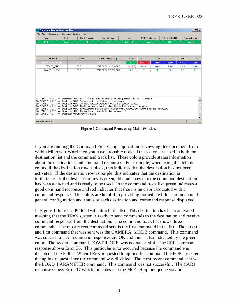
Figure 1 Command Processing Main Window
If you are running the Command Processing application or viewing this document from
within Microsoft Word then you have probably noticed that colors are used in both the
destination list and the command track list. These colors provide status information
about the destinations and command responses. For example, when using the default
colors, if the destination row is black, this indicates that the destination has not been
activated. If the destination row is purple, this indicates that the destination is
initializing. If the destination row is green, this indicates that the command destination
has been activated and is ready to be used. In the command track list, green indicates a
good command response and red indicates that there is an error associated with a
command response. The colors are helpful in providing immediate information about the
general configuration and status of each destination and command response displayed.
In Figure 1 there is a POIC destination in the list. This destination has been activated
meaning that the TReK system is ready to send commands to the destination and receive
command responses from the destination. The command track list shows three
commands. The most recent command sent is the first command in the list. The oldest
and first command that was sent was the CAMERA_MODE command. This command
was successful. All command responses are OK and this is also indicated by the green
color. The second command, POWER_OFF, was not successful. The ERR command
response shows Error 36. This particular error occurred because the command was
disabled at the POIC. When TReK requested to uplink this command the POIC rejected
the uplink request since the command was disabled. The most recent command sent was
the LOAD_PARAMETER command. This command was not successful. The CAR1
response shows Error 17 which indicates that the MCC-H uplink queue was full.
TREK-USER-023
4
5 Command Processing Menus
The Command Processing application contains six main menus: File, View,
Destination, Command, Options, and Help. Each of these menus is described in more
detail below.
5.1 File Menu
The File menu is used to create, open, and save command processing configurations and
to exit the Command Processing application. A Command Processing configuration is
comprised of the destinations in the destination list along with all the information
associated with each destination. For example, suppose you have 1 destination in the
destination list and this destination is configured with destination recording on. If you
save the configuration, all of this information will be saved in a file. Unlike Telemetry
Processing, Command Processing does not save database information (such as
information about the commands, calibrators etc.) in the file. However it does save other
information such as recording properties. There are a few other more general
configuration items which also get saved. These include the color preferences you set in
the Set Color Preferences dialog and the column configurations you specified in the
Command Processing Statistics dialog. When you save a configuration, the Command
Processing application will default to the
<base_path>\configuration_files\command_processing directory. The <base_path>
on a Windows 2000 computer for the computer is shown below.
<base_path> = C:\Documents and Settings\<username>\Application Data\TReK
If you would like to configure TReK to use a different default directory, you can set this
property using the Set Command Processing Options dialog. You can save your
configuration files anywhere you like, but a default directory provides an easy way for
you to keep up with your files.
Each of the items on the File menu is described below.
New
New provides a way to start a new configuration. When you start a new configuration
any destinations in the list are deleted and all activities associated with those destinations
(such as recording, viewing, etc.) are stopped. If there are destinations in the destination
list (or any other unsaved information in your current configuration) when New is
selected, you will be given the option of saving the configuration before the new
configuration is created. The New menu item will be insensitive when there are
destinations in the destination list which are initializing. As soon as the destination(s)
finish initializing the menu item will be available.
Open

TREK-USER-023
5
Open provides a way to open a previously saved configuration. If there are destinations
in the destination list (or any other unsaved information in your current configuration)
when Open is selected, you will be given the option of saving the current configuration
before the other configuration is opened. The Open menu item will be insensitive when
there are destinations in the destination list which are initializing. As soon as the
destination(s) finish initializing the menu item will be available.
Save
Save provides a way to save the current configuration. The Save menu item will be
insensitive when there are destinations in the destination list which are initializing. As
soon as the destination(s) finish initializing the menu item will be available.
Save As
Save As provides a way to save the current configuration with another name. The Save
As menu item will be insensitive when there are destinations in the destination list which
are initializing. As soon as the destination(s) finish initializing the menu item will be
available.
Exit
Exit provides a way to exit the Command Processing application. If there is any unsaved
information in your current configuration when Exit is selected, you will be given the
option of saving the current configuration before the application exits. The Exit menu
item will be insensitive when there are destinations in the destination list which are
initializing. As soon as the destination(s) finish initializing the menu item will be
available.
5.2 View Menu
The View menu is used to change attributes associated with the Command Processing
main window. There are five items on the View menu. Each is described below:
Status Bar
The Status bar is located at the very bottom of the Command Processing main window.
The status bar is used to display messages and useful information to you without
interrupting your work. The status bar has "panes," which include "indicators" and a
"message line." The indicators provide the status of items such as SCROLL LOCK. The
message line on the status bar can display information about program status or about a
toolbar button or menu item that you are pointing to with the mouse. If you select the
Status Bar item on the View menu, this will toggle the Status Bar on and off.
Configure Destination List Columns
The Configure Destination List Columns option brings up the Configure Destination List
Columns dialog. This dialog provides a way to add and remove columns in the
destination list. For example, you can add a column called “Max Retries” and remove
the column called “POIC Enablement”.
TREK-USER-023
6
Set Color Preferences
The Set Color Preferences option brings up the Set Color Preferences dialog. This dialog
can be used to turn off, turn on, or change the colors used in the Command Processing
application.
Set Main Window Command Track Preferences
The Set Main Window Command Track Preferences option brings up the Set Main
Window Command Track Preferences dialog. This dialog provides a way to set
preferences associated with the command track section of the main window (located in
the middle of the main window). For example, you can set the number of commands to
be displayed in the track.
Clear Message Area
As mentioned in section 4, the message area is located at the bottom of the Command
Processing main window. This is where important status and error messages will be
displayed while you are working with the application. If you select the Clear Message
Area item on the View menu, this will clear all the messages in the Message Area. Once
they have been cleared, you cannot get them back.
5.3 Destination Menu
The Destination menu is used to add destinations to the destination list in the main
window, and to control all the activities associated with each destination. Each of the
items on the Destination menu are described below.
Add POIC Destination
Used to enter information needed to establish a command connection with the POIC.
When you select Add POIC Destination, a tabbed dialog box will be presented so that
you can fill in the information your TReK system needs in order to establish a connection
with the POIC.
Add Suitcase Simulator Destination
Used to enter information needed to send commands to a Suitcase Simulator system.
When you select Add Suitcase Simulator Destination, a tabbed dialog box will be
presented so that you can fill in the information your TReK system needs in order to send
commands to a Suitcase Simulator.
Add PRCU Destination
Used to enter information needed to send commands to a PRCU system. When you
select Add PRCU Destination, a tabbed dialog box will be presented so that you can fill
in the information your TReK system needs in order to send commands to a PRCU.
Add RAPTR Destination

TREK-USER-023
7
Used to enter information needed to send commands to a RAPTR system. When you
select Add RAPTR Destination, a tabbed dialog box will be presented so that you can fill
in the information your TReK system needs in order to send commands to a RAPTR.
Add TReK Destination
Used to enter information needed to send commands to another TReK system. When you
select Add TReK Destination, a tabbed dialog box will be presented so that you can fill in
the information your TReK system needs in order to send commands to another TReK
system.
Activate Destination
Used to tell your TReK system to start doing something with the destination (what it does
depends on the type of destination and what you told it to do such as record, view
realtime messages, etc.). The Activate Destination option is only available when you
have a destination selected that has never been activated (i.e., Status is Inactive, CMD
Recording Status is Inactive, etc.) or if you have lost a connection.
View Realtime Login Messages
Used to tell your TReK system to display the incoming realtime Login messages
associated with a particular POIC or TReK destination.
View Realtime Commanding Messages
Used to tell your TReK system to display the incoming realtime commanding messages
associated with a particular destination.
Unblock Destination
This option is only available for POIC and TReK destinations. This will cause the
selected POIC or TReK destination to be “Clear to Send”. A dialog will be displayed to
confirm that you want to unblock the destination. When a destination is blocked, TReK
has not received information from the destination (POIC or TReK Command Node)
indicating that it is OK to send another request. By unblocking the destination, you will
enable TReK to send another request. However, it is likely that the destination (POIC or
TReK Command Node) will reject the request because it is not ready for the request. The
option to unblock a destination is provided in case a situation occurs where the interface
defined for commanding does not accurately reflect what really happens.
Enable Remote Subnode Commanding
Used to tell your TReK system to enable remote commanding for any subnodes
connected to this destination. This option will only be available if the destination is
allowing remote connections, and the current subnode remote commanding status is
disabled.
Disable Remote Subnode Commanding
Used to tell your TReK system to disable remote commanding for any subnodes
connected to this destination. This option will only be available if the destination is
TREK-USER-023
8
allowing remote connections, and the current subnode remote commanding status is
enabled.
Deactivate Destination
Used to tell your TReK system to stop communicating with a particular destination.
When you select a destination in the destination list, and then select the Deactivate
Destination option, the destination will be deactivated and your TReK system will stop
communicating with that particular destination. Any other activities associated with that
destination such recording or viewing will also stop because your TReK system will no
longer be communicating with the destination. The Deactivate Destination option is only
available when you have an active destination selected. If you want to delete the
destination from the list, use the Delete Destination option.
Delete Destination
Used to tell your TReK system to delete a particular destination. When you select a
destination in the destination list, and then select the Delete Destination option, the
destination will be removed from the list and your TReK system will stop all activities
associated with that particular destination. The Delete Destination option is only
available when you have a destination selected.
Show Destination Properties
Used to see a complete list of properties about a particular destination. This includes
information such as the database, whether the commanding messages associated with the
destination are to be recorded, etc. The destination properties are defined when you add
the destination to the destination list using one of the Add dialogs such as the Add POIC
Destination dialog or the Add Suitcase Simulator Destination dialog. In fact, when you
select Show Destination Properties the dialog box that appears looks just like the dialog
you used to add the destination to the destination list. You can use this menu item or use
the left mouse button to double click on the destination to bring up the Show Destination
Properties dialog.
5.4 Command Menu
The command menu is used to access various dialog boxes associated with commands.
For example, if you would like to see a list of commands associated with a particular
destination, you would select the ‘Commands’ menu item. If you would like to see a list
of all the commands sent from your TReK system you would select the “Command
Track’ menu item. The following list identifies some of the common functions that can
be performed using the capabilities available from the Command menu:
View a list of all commands associated with each destination.
View a list of all command headers associated with each destination.
View a list of all commands sent from your TReK system.
View a list of all command field calibrators associated with each
command/destination.

TREK-USER-023
9
Each menu item on the Command menu is described below:
Commands
Provides access to the Commands dialog box which lists all of the commands associated
with each destination.
Command Headers
Provides access to the Command Headers dialog box which lists all of the command
headers associated with each command/destination.
Command Track
Provides access to a list of all the commands sent from your TReK system since the
Command Processing application was started.
Command Field Calibrators
Provides access to the Calibrators dialog box which lists all of the calibrators that are in
use.
5.5 Options Menu
The Options menu is used to access information about general command processing
attributes and specific command processing status information. Each of the items on the
Options menu is described below.
Show Login Sessions
Used to see a list of all Login Sessions to other systems. This includes ERIS Login
Sessions and TReK Login Sessions.
Set Command Processing Options
Used to set TReK command processing options.
Show Command Processing Statistics
Used to view specific command processing statistics information. This includes
information such as the number of packets received, the number of packets sent, etc. In
most cases, this statistics information will only be needed when you need to perform
trouble-shooting.
Recorded Data Viewer
Provides access to the Recorded Data Viewer. The Recorded Data Viewer is used to
view information stored in a TReK recording file.
Manage Subnode Connections
Used to view and manage subnode connections.

TREK-USER-023
10
5.6 Help Menu
The Help menu is used to access on-line help for the Command Processing application.
Each of the items on the Help menu is described below.
Help Topics
Used to access the typical Windows Contents and Index on-line help window.
About Command Processing
Used to view the About Command Processing dialog.
5.7 Destination List Pop-Up Menu
The Destination List pop-up menu can be accessed by clicking the right mouse button in
the destination list area of the main window. If you right click in the destination list area
of the window, but you do not click on a destination in the list, many of the menu items
will be insensitive. This is because many of the menu items are only applicable when a
destination is selected. If you right click on a destination in the destination list all the
menu items which are applicable to that particular destination at that moment in time will
be sensitive. The Destination List Pop-Up menu contains all the items on the Destination
menu on the menu bar plus the following items:
Start Login Recording
Used to tell your TReK system to start recording a particular Login session. (Login
Session Recording can be set up when you initially add a POIC or TReK Destination to
the list, but if you don’t specify Login Session recording at that time it can be added later
using this menu option).
Pause Login Recording
Used to tell your TReK system to pause recording for a particular login session. Please
note that this will only pause recording. The Pause Login Recording option is only
available when you have a destination selected with a Login Recording Status of
Recording.
Resume Login Recording
Used to tell your TReK system to resume recording for a particular login session. The
Resume Login Recording option is only available when you have a Destination selected
with a Login Recording Status of Paused.
Stop Login Recording
Used to tell your TReK system to stop recording a particular login session. The Stop
Login Recording option is only available when you have a Destination selected with a
Login Recording Status of Recording or Paused.
Start Commanding Recording
TREK-USER-023
11
Used to tell your TReK system to start recording a particular command session.
(Commanding Recording can be set up when you initially add a Destination to the list,
but if you don’t specify recording at that time it can be added later using this menu
option).
Pause Commanding Recording
Used to tell your TReK system to pause recording for a particular command session.
Please note that this will only pause recording. The Pause Commanding Recording
option is only available when you have a destination selected with a CMD Recording
Status of Recording.
Resume Commanding Recording
Used to tell your TReK system to resume recording for a particular command session.
The Resume Commanding Recording option is only available when you have a
Destination selected with a CMD Recording Status of Paused.
Stop Commanding Recording
Used to tell your TReK system to stop recording a particular command session. The Stop
Commanding Recording option is only available when you have a Destination selected
with a CMD Recording Status of Recording or Paused.
5.8 Windows Edit Pop-Up Menu
The standard Windows Edit Pop-Up Menu can be accessed whenever your cursor is
located inside an edit field inside the Command Processing application. This menu
contains the standard edit commands such as Cut, Copy, and Paste.
6 Command Processing Dialog Boxes
This section describes all the dialogs in the Command Processing application. For an
example of how some of these dialogs are used while working with the Command
Processing application please see the TReK Command Applications Tutorial (TREK-
USER-021).
6.1 Configure Destination List Columns Dialog
The Configure Destination List Columns dialog is shown in Figure 2. This dialog is used
to configure the columns shown in the main window destination list. You will probably
configure the columns shown based on the type of destination you are working with. For
example, there is quite a bit more information associated with a POIC destination versus
a Suitcase Simulator destination. For information about what these columns mean, please
reference the TReK Command Tutorial (TREK-USER-020) or the POIC to Generic User
Interface Definition Document (SSP-50305).

TREK-USER-023
12
Figure 2 Configure Destination List Columns Dialog
Each field and control on the Configure Destination List Columns dialog is described
below.
Available Columns
The Available Columns list contains the columns that are not currently being displayed.
Destination List Columns
This Destination List Columns list contains the columns that are currently being
displayed.
Buttons
There are several non-standard buttons on the Configure Destination List Columns
dialog. Each is described below.
Right Arrow (>)
This button can be selected when an item in the Available Columns list is selected. If
you push this button it will move the selected item from the Available Columns list to the
Destination List Columns list.
Left Arrow (<)

TREK-USER-023
13
This button can be selected when an item in the Destination List Columns list is selected.
If you push this button it will move the selected item from the Destination List Columns
list to the Available Columns list. Please note that the Name column must always be
shown and it must always be the first column in the destination list. Therefore, if you
attempt to move the name column out of the Destination List Columns list you will get an
error message.
Up
This button can be selected when an item in the Destination List Columns list is selected.
If you push this button it will move the item up in the list. Please note that the Name
column must always be shown and it must always be the first column in the destination
list. Therefore, if you attempt to move something into the first position you will get an
error message.
Down
This button can be selected when an item in the Destination List Columns list is selected.
If you push this button it will move the item down in the list. Please note that the Name
column must always be shown and it must always be the first column in the destination
list. Therefore, if you attempt to move the name column down in the list you will get an
error message.
Set To Defaults
The Set To Defaults button will reset the Available Columns and Destination List
Columns to the original values that were in place when the TReK software was installed.
6.2 Set Color Preferences (Main Window Colors Tab) Dialog
The Set Color Preferences (Main Window Colors Tab) Dialog is shown in Figure 3
below. This dialog has two tabs: a Main Window Colors tab and a Commands Dialog
Colors tab.
The Main Window Colors tab is used to control the color feature associated with the
Command Processing main window destination list and main window command track
list. The Command Processing application checks the status of each destination in the
destination list. The color of a destination in the destination list indicates the
destination’s status. Colors are also used to indicate the status of each command
response. The color feature can be turned off. If it is off the destinations in the
destination list will always be white (gray when selected) and the command responses
will always be white (gray when selected). If the color feature is on, the destinations in
the destination list and the command responses in the command track list will turn a
specific color based on the status and the colors assigned in the Set Color Preferences
dialog.

TREK-USER-023
14
Figure 3 Set Color Preferences (Main Window Colors Tab) Dialog
Each field and control on the Set Color Preferences (Main Window Colors Tab) Dialog is
described below.
Color On
Turns the color feature on.
Color Off
Turns the color feature off.
No Status Color
The color assigned when the status of the destination is “Inactive”. “Inactive” indicates
that there is no information available about the destination. This will be the case when
the destination has been added to the destination list, but it has not been activated. In this
situation your TReK system has not been told to do anything about the destination and
therefore has no status information about the destination. (Default Color: Black)

TREK-USER-023
15
Initializing Color
The color assigned when the status of the destination is “Initializing”. This status will
occur when the destination is in the process of activating. (Default Color: Purple)
Active Color
The color assigned when the status of the destination is “Active”. This status will occur
when the destination has been activated and your TReK system is ready to send
commands to the destination. (Default Color: Green)
Lost Connection Color
The color assigned when the status of the destination is “Lost Connection”. This status
will occur when the destination has been activated and the connection with the
destination is lost. (Default Color: Orange)
Error Condition Color
The color assigned when the status of the destination is unknown. This will occur if the
destination has been activated, but an error occurs while trying to determine the status of
the destination. (Default Color: Red)
No Command Response Color
The color assigned when the command response has not been returned. (Default Color:
Blue)
Command Response OK Color
The color assigned when the command response has been returned and shows success.
(Default Color: Green)
Command Response Error Color
The color assigned when the command response has been returned and shows that an
error occurred. (Default Color: Red)
Buttons
Select Color
The Select Color button is used to access the standard Windows Color dialog in order to
change the assigned color.
Set to Defaults
The Set to Defaults button will reset all the fields and controls in the Set Color
Preferences Main Window Colors tab to the original values that were in place when the
TReK software was installed.
TREK-USER-023
16
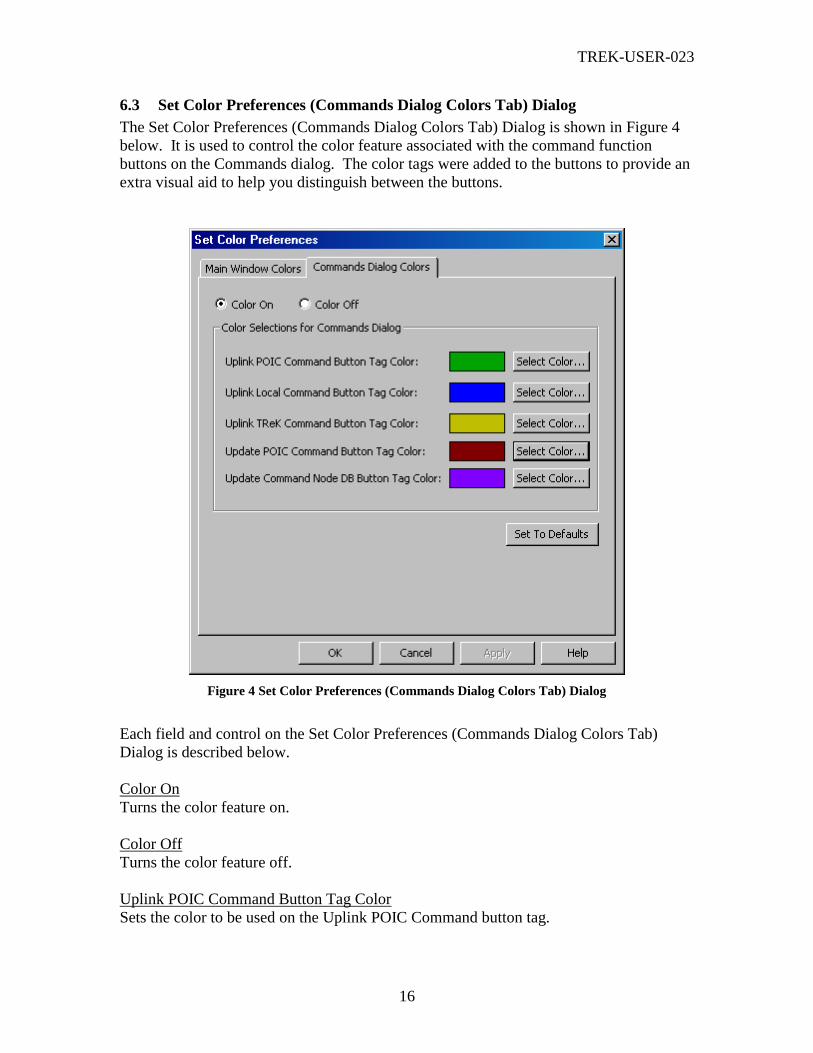
6.3 Set Color Preferences (Commands Dialog Colors Tab) Dialog
The Set Color Preferences (Commands Dialog Colors Tab) Dialog is shown in Figure 4
below. It is used to control the color feature associated with the command function
buttons on the Commands dialog. The color tags were added to the buttons to provide an
extra visual aid to help you distinguish between the buttons.
Figure 4 Set Color Preferences (Commands Dialog Colors Tab) Dialog
Each field and control on the Set Color Preferences (Commands Dialog Colors Tab)
Dialog is described below.
Color On
Turns the color feature on.
Color Off
Turns the color feature off.
Uplink POIC Command Button Tag Color
Sets the color to be used on the Uplink POIC Command button tag.

TREK-USER-023
17
Uplink Local Command Button Tag Color
Sets the color to be used on the Uplink Local Command button tag.
Uplink TReK Command Button Tag Color
Sets the color to be used on the Uplink TReK Command button tag.
Update POIC Command Button Tag Color
Sets the color to be used on the Update POIC Command button tag.
Update Command Node DB Button Tag Color
Sets the color to be used on the Update Command Node DB button tag.
Buttons
Select Color
The Select Color button is used to access the standard Windows Color dialog in order to
change the assigned color.
Set to Defaults
The Set to Defaults button will reset all the fields and controls in the Set Color
Preferences Commands Dialog Colors tab to the original values that were in place when
the TReK software was installed.
6.4 Set Main Window Command Track Preferences Dialog
The Set Main Window Command Track Preferences dialog is shown in Figure 5. This
dialog is used to configure the main window command track list. You can turn the main
window command track off. This will only turn off the display of the messages in the
main window. TReK will still be tracking all commands sent and the complete list of
command track messages is always available in the Command Track dialog (available
from the Command menu). Please keep in mind that it’s a good idea to set the ‘Number
of Commands To Display’ to a small number. Each time a command is sent the main
window will be updated to display the new information. Therefore, if the main window
command track list gets large TReK will use more memory and CPU resources to refresh
all the information shown in the list.

TREK-USER-023
18
Figure 5 Set Main Window Command Track Preferences Dialog
Each field and control on the Set Main Window Command Track Preferences dialog is
described below.
Main Window Command Track Off
If the Main Window Command Track is off, no commands will be displayed in the mian
window command track area.
Main Window Command Track On
If the Main Window Command Track is on, the number of commands listed will
correspond to the ‘Number of Commands To Display’ value.
TReK Receipt Response (TRR) Column Off
If the TReK Receipt Response column is off, the TRR column will not be displayed in
the command track area. The TReK Receipt Response is only applicable for TReK
destinations.
TReK Receipt Response (TRR) Column On
If the TReK Receipt Response column is on, the TRR column will be displayed in the
command track area. The TReK Receipt Response is only applicable for TReK
destinations.
Number of Commands To Display
Adjusts the number of commands to display in the command track area.
6.5 Add POIC Destination (General Tab) Dialog
The Add POIC Destination dialog is shown in Figure 6. This dialog is used to add a
POIC Destination to the destination list in the main window. This is how you tell your
TReK system the information it needs to establish a command connection with the POIC.
There are four tabs in the Add POIC Destination dialog (when adding a destination).
After the POIC destination has been activated, the Destination properties dialog has six
tabs.
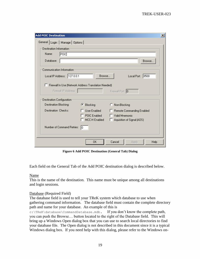
TREK-USER-023
19
Figure 6 Add POIC Destination (General Tab) Dialog
Each field on the General Tab of the Add POIC destination dialog is described below.
Name
This is the name of the destination. This name must be unique among all destinations
and login sessions.
Database (Required Field)
The database field is used to tell your TReK system which database to use when
gathering command information. The database field must contain the complete directory
path and name for your database. An example of this is
c:\TReK\database\CommandDatabase.mdb. If you don’t know the complete path,
you can push the Browse… button located to the right of the Database field. This will
bring up a Windows Open dialog box that you can use to search local directories to find
your database file. The Open dialog is not described in this document since it is a typical
Windows dialog box. If you need help with this dialog, please refer to the Windows on-
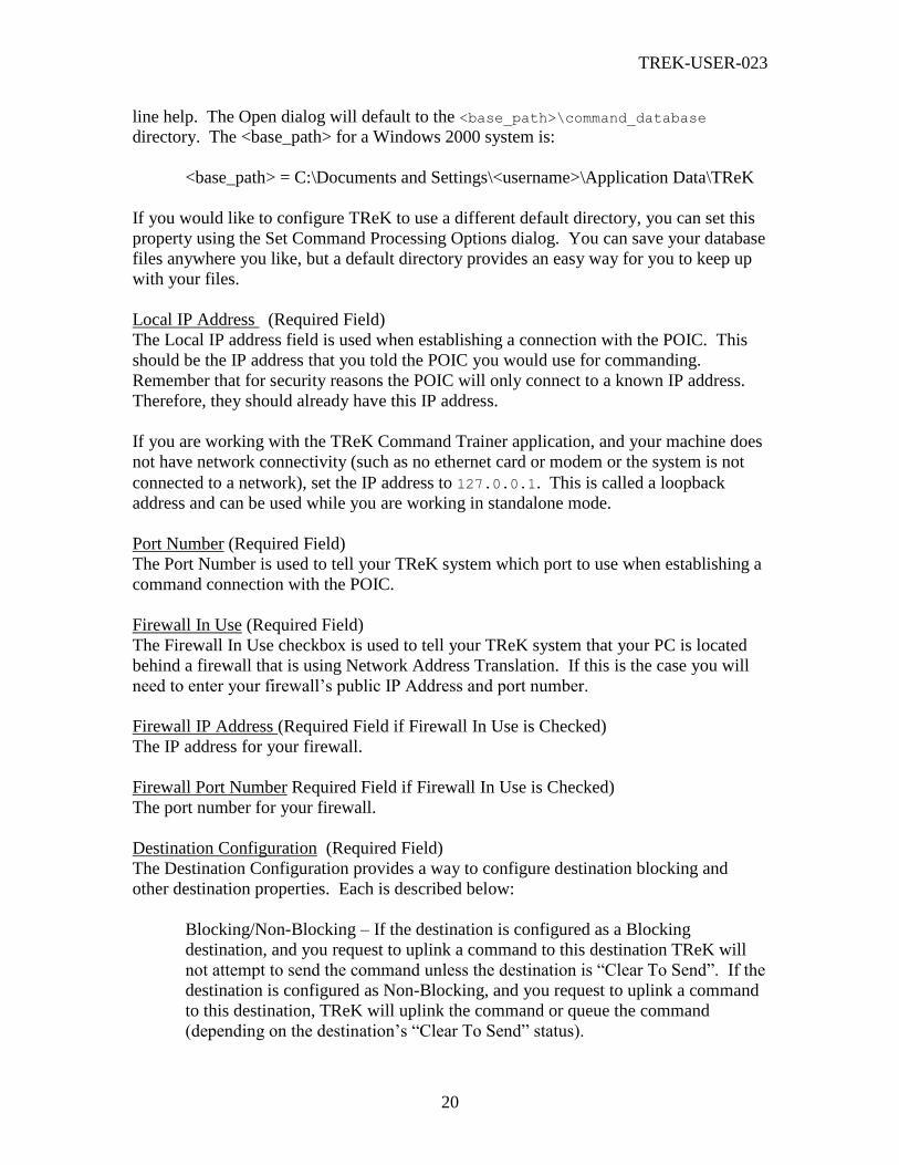
TREK-USER-023
20
line help. The Open dialog will default to the <base_path>\command_database
directory. The <base_path> for a Windows 2000 system is:
<base_path> = C:\Documents and Settings\<username>\Application Data\TReK
If you would like to configure TReK to use a different default directory, you can set this
property using the Set Command Processing Options dialog. You can save your database
files anywhere you like, but a default directory provides an easy way for you to keep up
with your files.
Local IP Address (Required Field)
The Local IP address field is used when establishing a connection with the POIC. This
should be the IP address that you told the POIC you would use for commanding.
Remember that for security reasons the POIC will only connect to a known IP address.
Therefore, they should already have this IP address.
If you are working with the TReK Command Trainer application, and your machine does
not have network connectivity (such as no ethernet card or modem or the system is not
connected to a network), set the IP address to 127.0.0.1. This is called a loopback
address and can be used while you are working in standalone mode.
Port Number (Required Field)
The Port Number is used to tell your TReK system which port to use when establishing a
command connection with the POIC.
Firewall In Use (Required Field)
The Firewall In Use checkbox is used to tell your TReK system that your PC is located
behind a firewall that is using Network Address Translation. If this is the case you will
need to enter your firewall’s public IP Address and port number.
Firewall IP Address (Required Field if Firewall In Use is Checked)
The IP address for your firewall.
Firewall Port Number Required Field if Firewall In Use is Checked)
The port number for your firewall.
Destination Configuration (Required Field)
The Destination Configuration provides a way to configure destination blocking and
other destination properties. Each is described below:
Blocking/Non-Blocking – If the destination is configured as a Blocking
destination, and you request to uplink a command to this destination TReK will
not attempt to send the command unless the destination is “Clear To Send”. If the
destination is configured as Non-Blocking, and you request to uplink a command
to this destination, TReK will uplink the command or queue the command
(depending on the destination’s “Clear To Send” status).

TREK-USER-023
21
User Enabled – If you request to uplink a command to this destination, TReK will
only attempt to send it if the POIC status shows that you are enabled for
commanding.
POIC Enabled -- If you request to uplink a command to this destination, TReK
will only attempt to uplink the command if the POIC status shows that the POIC
is enabled for commanding.
MCC-H Enabled -- If you request to uplink a command to this destination, TReK
will only attempt to uplink the command if the POIC status shows that the MCC-
H is enabled for commanding.
Remote Commanding Enabled -- If you request to uplink a command to this
destination, TReK will only attempt to uplink the command if the POIC Status
shows that Remote Commanding is enabled. (Note: Remote Commanding is also
referred to as Non-EHS Commanding).
Valid Mnemonic -- If you request to uplink a command to this destination, TReK
will only attempt to uplink the command if the POIC shows that this command
mnemonic is enabled.
Note: If the check for Valid Mnemonic is performed on a Non-Blocking Destination
and the mnemonic provided by the user is invalid, the destination will hang (i.e., it
keeps checking to see if the mnemonic is valid). It is suggested that you do not use
the Valid Mnemonic check for Non-Blocking destinations. If this occurs
operationally, just change the destination’s properties to not check for invalid
mnemonics.
Acquisition of Signal -- If you request to uplink a command to this destination,
TReK will only attempt to uplink the command if the POIC shows Acquisition of
Signal (AOS).
Number of Command Retries (Required Field)
This value indicates how many times the POIC should attempt to retry a command
uplink. The POIC is configured with an overall maximum number of command retries.
The value you enter cannot exceed this maximum. The POIC’s “Max Retries” value is
returned when the destination is activated. You can see this value in the Command
Processing main window (if you add this column) or in the POIC Destination Properties
dialog (Configuration Tab). Since the POIC’s “Max Retries” value is configurable, it’s
possible it may change. If the POIC changes their “Max Retries” value to a value that is
less than the value you are using, your value will automatically be reset to match the
POIC’s value. If this occurs, you will be notified via a message in the Command
Processing main window message area.

TREK-USER-023
22
6.6 Add POIC Destination (Login Tab) Dialog
The Login Tab, shown in Figure 7, provides a way to identify an ERIS Login session to
use with this POIC Destination. It is possible to share an ERIS Login Session among
several POIC Destinations. When the POIC Destination is activated, it will activate the
ERIS Login Session if it is inactive or use the active ERIS Login Session if it is already
active. To add an ERIS Login Session to the list, push the Add button. Once an ERIS
Login Session is in the list, it can be modified using the Modify button. If an ERIS Login
Session is in the list and is inactive, it can be deleted using the Delete button.
Figure 7 Add POIC Destination (Login Tab) Dialog
Note: When you select to Modify an ERIS Login Session, the name of the ERIS Login
Session cannot be modified (regardless of whether the ERIS Login Session is active or
inactive). If you need to change the name, you will need to add a new ERIS Login Session.
The old ERIS Login Session will be considered “in use” until you leave the dialog. Therefore,
if you want to delete it you need to delete it after you leave this dialog.
Note2: All the ERIS Login Session list changes you make on this tab take place immediately
and cannot be cancelled. The only item on this tab that can be cancelled is the ERIS Login

TREK-USER-023
23
Session to be used by this destination. If you push the Cancel button to cancel all the
actions taken in the dialog, the ERIS Login Session assignment will be reset but the ERIS
Login Sessions added, modified, or deleted will not be cancelled or reset.
6.7 Add ERIS Login Session (General Tab) Dialog
The Add ERIS Login Session dialog is shown in Figure 8. This dialog is used to Add an
ERIS Login Session to the ERIS Login Session list in the Login Tab of the Add POIC
Destination dialog. It has a General tab and an Options tab.
Figure 8 Add ERIS Session Dialog
Each field and control on the Add ERIS Login Session (General Tab) dialog is described
below.
Name
This is the name of the ERIS Login Session. This name must be unique among all
destinations and login sessions.
POIC Host Name
When entering information needed to establish a connection with the POIC you can enter
the POIC Host Name or the POIC IP Address. The POIC Host Name menu lists all the
available POIC host names. When you select a host name, the IP Address in the POIC IP
Address field will not be updated until the destination is activated.
POIC IP Address

TREK-USER-023
24
The IP Address to connect to at the POIC.
POIC Port
The Port Number to use when connecting to the POIC. This should be provided to you
by the POIC.
Username
The username for your POIC Account. This should be provided to you by the POIC. If
you leave this field blank you will be prompted to enter this information when you
activate this destination. (During the activation sequence when TReK is establishing a
connection with the POIC, ERIS will prompt you to log in to your POIC account).
Password
The password for your POIC Account. This should be provided to you by the POIC. If
you save your configuration, the password will not be saved in the configuration file.
This has been done for security reasons.
MOP
The Mission/Operational Support Mode/Project (MOP) to log into when you log into
your POIC account. If you don’t know the MOP then just leave this field blank. If you
leave this field blank you will be prompted to select a MOP from a list during the Log In
sequence. If you enter a MOP into this field then the application will try to use the MOP
you enter and will only prompt you if the MOP you entered is not available. If you log
into a POIC account in which there is only one mop available, then the POIC will
automatically log you into that MOP. In this case, the POIC does not send a MOP
request to TReK.
6.8 Add ERIS Login Session (Options Tab) Dialog
The Add ERIS Login Session Options Tab is shown in Figure 8. This tab is used to
configure recording and viewing properties for the ERIS Login Session.

TREK-USER-023
25
Figure 9 Add ERIS Login Session (Options Tab) Dialog
Each field and control on the Add ERIS Login Session (Options Tab) dialog is described
below.
Recording (Required Field)
The Recording option is used to tell your TReK system whether the ERIS Login Session
should be recorded. In the main window the recording status for this recording will be
labeled “Login Recording”. The Login Recording status is not shown in the default main
window configuration. By using the ‘Configure Destination List Columns’ menu option
on the View menu you can add this column to the main window list.
Base Filename (Required Field if Recording is On)
When your TReK system records an ERIS Login Session, the raw data is stored in one or
more files in a local directory. A base filename (provided by you) is used as the base
name of the file and the rest of the file name is generated by your TReK system. The
complete filename indicates the time the file was created and closed. When you want to
play the data back, you will be asked to provide this Base Filename. Therefore, you
should try to select a meaningful name that will be easy to remember and is closely
associated with the data that you are recording.
Directory (Required Field if Recording is On)
The Directory information is used to tell your TReK system which directory should be
used when storing your data recording files. When you want to play the data back, you
will be asked to provide this Directory information so your TReK system can find the
files. This field requires a complete directory path. An example of this is

TREK-USER-023
26
c:\MyRecordingFiles\. If you don’t like to type or you need help defining the
complete path, you can push the … (dot dot dot) button located to the right of the
Directory field. This will bring up a Windows Browse for Folder dialog which you can
use to identify the local directory path where you want to store your recorded data files.
The Browse for Folder dialog is not described in this document since it is a typical
Windows dialog box. If you need help with this dialog, please refer to your Windows on-
line help.
Viewing (Required Field)
The Viewing option is used to tell your TReK system whether the realtime messages
associated with the ERIS Login Session should be available for viewing. Viewing does
use CPU and memory resources. Therefore, remember that if you start to run low on
resources it is possible to turn viewing off.
Buffer Size (# Messages) (Required if Viewing is On)
The Buffer Size tells your TReK system how many realtime messages to store in memory
at a time. The buffer will wrap and older messages will be overwritten. This is a
safeguard against using up too much memory.
6.9 Add POIC Destination (Manage Tab) Dialog
The Manage tab, shown in Figure 19, is used to configure the destination so it can be
used by remote users.

TREK-USER-023
27
Figure 10 Add POIC Destination (Manage Tab) Dialog
Each field on the Manage Tab of the Add POIC Destination (Manage Tab) dialog is
described below.
Allow Incoming Connections (Required Field)
The Allow Incoming Connections option is used to tell your TReK system whether to
allow remote users to connect to this destination.
Remote Subnode Commanding (Required Field)
The Remote Subnode Commanding setting is used to configure the destination to accept
or reject commanding requests from remote users (subnodes) that are connected to the
destination. The options are “Enabled” or “Disabled”. If the remote subnode
commanding status is set to “Enabled”, then incoming commanding requests from
subnodes will be evaluated and executed if they meet the proper criteria. If the remote
subnode commanding status is set to “Disabled”, then all incoming requests will
automatically be rejected.
Destination User Templates (Required Fields)
This area of the dialog is used to define which remote users can use this destination. You
can specify a particular list of users or you can configure the destination so that anyone
can use it. If you specify a particular list of users, then only those users can use the
destination. This implies that a user must login using one of the usernames on the list in
order to use the destination. For this to work the Remote Services security configuration
must be set to “Login Required”. If the Remote Services security configuration is set to
one of the security settings that does not require a login, then there will be no usernames
associated with remote user connections and none of the remote users will be allowed to
use the destination (because they are not on the list). On the other hand, if you select the
“Anyone” radio button this configures the destination so that anyone can use it. The
remote services security configuration does not come into play with this configuration
since no username is required. If the security setting does not require a login then any
remote user that connects can use this destination (regardless of whether they logged in
with a username or not). If the security setting does require a login, then anyone logging
in (using any username) can use the destination. For more information about managing
security associated with destinations, please refer to Appendix C Managing Destination
Security. Appendix C contains examples showing the results of different combinations
of security configurations and destination user settings.
For each destination user template, the list shows the username, the user’s initial uplink
status, and the number of owner ids assigned to the user. If you select the “Anyone”
radio button the “anyone” user will be the only user in the list. The properties associated
with the “anyone” user can be modified, but the “anyone” user cannot be deleted.
Buttons

TREK-USER-023
28
Add
When you push the Add button the Add Destination User Template dialog is displayed.
This dialog is described in section 6.10. The Add Destination User Template dialog
provides a way to define a destination user template.
Modify
When you push the Modify button the Modify Destination User Template dialog is
displayed. The Modify Destination User Template dialog provides a way to modify a
destination user template. This dialog is identical to the Add Destination User Template
dialog except the username is not modifiable.
Delete
The Delete button is used to delete a destination user template.
Advanced
When you push the Advanced button the Advanced Management dialog is displayed.
This dialog is described in section 6.17. The Advanced Management dialog provides a
way to configure advanced management properties associated with the destination. For
example, you can identify which command functions the destination will extend to
remote users.
6.10 Add Destination User Template (General Tab) Dialog
The Add Destination User Template (General Tab) Dialog is shown in Figure 11. This
dialog is used to define the default properties associated with a destination user. You
should think of a destination user as a template. This template is used in two different
ways: 1) it identifies the characteristics of a remote user who is allowed to connect to the
destination, and 2) it defines a specific set of default properties that will be associated
with that user when they connect to the destination. These properties include the user’s
initial uplink status, the initial list of owner ids associated with the user (which defines
the commands the user can update/uplink), and initial recording and viewing properties
associated with the user’s connection. It’s very important to remember that this is a
template and these are default properties that are assigned when the user connects to the
destination. Once a user is connected to the destination, changing these properties will
not change the properties associated with the connection. They will only change the
default properties associated with this template thereby affecting the next remote user that
connects matching this template (username). The Manage Subnode Connections dialog
is used to change the realtime properties associated with a specific unique connection.
Therefore, if you wanted to change the uplink status or recording properties for a specific
remote user connection you would do this using the Manage Subnode Connections dialog
(not the Destination User Template dialog). The Destination User Template dialog only
changes the template that is used when a user first connects to the destination.
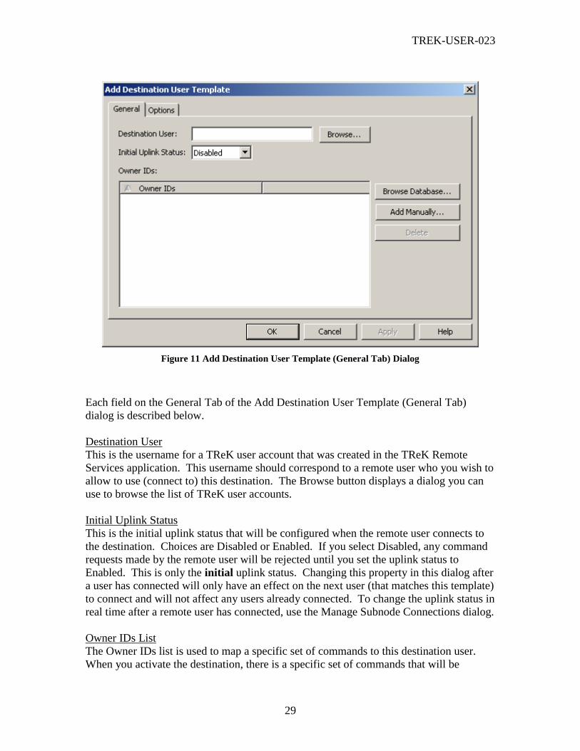
TREK-USER-023
29
Figure 11 Add Destination User Template (General Tab) Dialog
Each field on the General Tab of the Add Destination User Template (General Tab)
dialog is described below.
Destination User
This is the username for a TReK user account that was created in the TReK Remote
Services application. This username should correspond to a remote user who you wish to
allow to use (connect to) this destination. The Browse button displays a dialog you can
use to browse the list of TReK user accounts.
Initial Uplink Status
This is the initial uplink status that will be configured when the remote user connects to
the destination. Choices are Disabled or Enabled. If you select Disabled, any command
requests made by the remote user will be rejected until you set the uplink status to
Enabled. This is only the initial uplink status. Changing this property in this dialog after
a user has connected will only have an effect on the next user (that matches this template)
to connect and will not affect any users already connected. To change the uplink status in
real time after a remote user has connected, use the Manage Subnode Connections dialog.
Owner IDs List
The Owner IDs list is used to map a specific set of commands to this destination user.
When you activate the destination, there is a specific set of commands that will be

TREK-USER-023
30
associated with the destination. But these commands will not be accessible to the
destination user (subnode) unless you add the owner IDs associated with the commands
to this owner list. It may be that you only want to map a subset of the destination’s
commands to the destination user. The way you do this is by only adding owner IDs
associated with commands you want this destination user to have access to. For more
information please reference Appendix D Using Owner IDs to Map Commands to
Destination Users.
Buttons
Browse
The Browse button will display the Browse For User Dialog. This dialog provides a way
to view a list of all the TReK user accounts and select one from the list. This dialog is
described in section 6.11.
Browse Database
When you push the Browse Database button, the Browse Database For Owner IDs Dialog
will be displayed. This dialog can be used to browse a command database to select a
specific set of owner IDs to add to the Owner IDs list. This dialog is described in section
6.12.
Add Manually
When you push the Add Manually button, the Add Owner Dialog will be displayed. This
dialog provides a way to manually enter an owner ID to the list. Please note that there
are no checks to ensure that you are entering a valid owner ID. It is possible to enter
invalid data (which will be ignored). This dialog is described in section 6.13.
Delete
The Delete button is used to delete an owner ID from the Owner IDs list.
6.11 Browse For User Dialog
The Browse For User dialog is shown in Figure 12. This dialog is used to browse the
remote user account list that is defined through the Remote Services application. Using
this dialog you can select a user in the list.
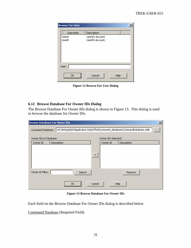
TREK-USER-023
31
Figure 12 Browse For User Dialog
6.12 Browse Database For Owner IDs Dialog
The Browse Database For Owner IDs dialog is shown in Figure 13. This dialog is used
to browse the database for Owner IDs.
Figure 13 Browse Database For Owner IDs
Each field on the Browse Database For Owner IDs dialog is described below.
Command Database (Required Field)

TREK-USER-023
32
This field will default to the database you entered on the General Tab of the Add POIC
Destination dialog. While you can change this entry, it is highly recommended that you
use the same database that you are using for the destination.
Owner IDs in Database
This list shows the list of owner ids in the database that were returned when you pushed
the Search button. The Owner ID filter can be used to limit the search. If the Owner ID
filter field is empty all Owner IDs in the database will be returned.
Owner IDs Selected
This list shows the owner ids that you have selected. This is the list that will be added to
the destination user template Owner IDs list.
Buttons
Search
When you push the search button, the database will be searched and filtered according to
the filter you entered in the Owner ID Filter field.
> (Arrow Button)
When you push the > button, all the Owner IDs you have selected in the Owner IDs in
Database list will be moved to the Owner IDs Selected list. You can select multiple
Owner IDs in the list by holding down the Ctrl key.
Remove
The Remove button is used to remove an owner id from the Owner IDs Selected list.
6.13 Add Owner Dialog
The Add Owner dialog is shown in Figure 14. This dialog is used to enter an Owner ID
into an Owner ID list. Please note that there is no validation checking to ensure that the
Owner ID you entered exists. It is possible to enter an invalid Owner ID.
Figure 14 Add Owner Dialog
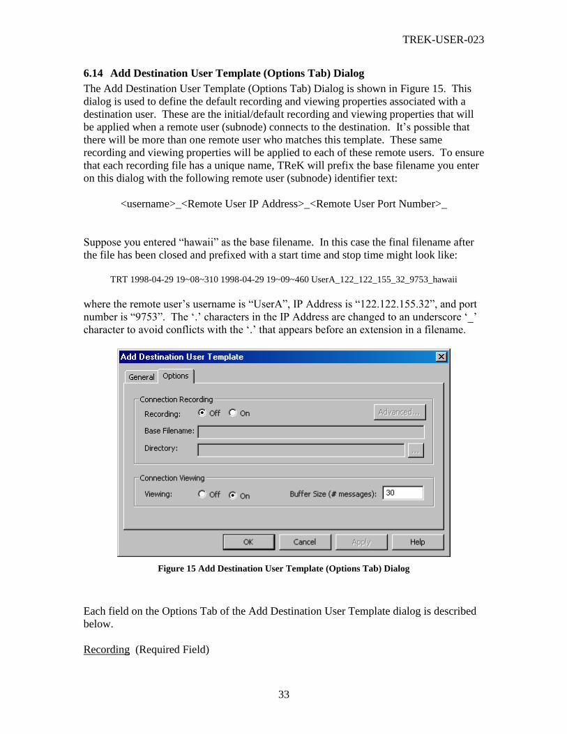
TREK-USER-023
33
6.14 Add Destination User Template (Options Tab) Dialog
The Add Destination User Template (Options Tab) Dialog is shown in Figure 15. This
dialog is used to define the default recording and viewing properties associated with a
destination user. These are the initial/default recording and viewing properties that will
be applied when a remote user (subnode) connects to the destination. It’s possible that
there will be more than one remote user who matches this template. These same
recording and viewing properties will be applied to each of these remote users. To ensure
that each recording file has a unique name, TReK will prefix the base filename you enter
on this dialog with the following remote user (subnode) identifier text:
<username>_<Remote User IP Address>_<Remote User Port Number>_
Suppose you entered “hawaii” as the base filename. In this case the final filename after
the file has been closed and prefixed with a start time and stop time might look like:
TRT 1998-04-29 19~08~310 1998-04-29 19~09~460 UserA_122_122_155_32_9753_hawaii
where the remote user’s username is “UserA”, IP Address is “122.122.155.32”, and port
number is “9753”. The ‘.’ characters in the IP Address are changed to an underscore ‘_’
character to avoid conflicts with the ‘.’ that appears before an extension in a filename.
Figure 15 Add Destination User Template (Options Tab) Dialog
Each field on the Options Tab of the Add Destination User Template dialog is described
below.
Recording (Required Field)

TREK-USER-023
34
The Recording option is used to tell your TReK system whether the commanding session
should be recorded. This commanding session is the connection between the destination
(command node) and the remote user (subnode).
Base Filename (Required Field if Recording is On)
When your TReK system records a commanding session, the raw data is stored in one or
more files in a local directory. A base filename (provided by you) is used as the base
name of the file and the rest of the file name is generated by your TReK system. The
complete filename includes the time the file was created and closed, the remote user’s
username, the remote user’s IP address, the remote user’s port number, and this base
filename.
Directory (Required Field if Recording is On)
The Directory information is used to tell your TReK system which directory should be
used when storing your data recording files.
Viewing (Required Field)
The Viewing option is used to tell your TReK system whether the realtime messages
associated with the commanding session should be available for viewing.
Buffer Size (# Messages) (Required if Viewing is On)
The Buffer Size tells your TReK system how many realtime messages to store in memory
at a time. The buffer will wrap and older messages will be overwritten. This is a
safeguard against using up too much memory.
6.15 Modify Destination User Template (General Tab) Dialog
The Modify Destination User Template (General Tab) dialog is shown in Figure 16. This
dialog provides a way to modify the properties of a destination user template. When you
modify a Destination User Template you cannot modify the Username. If you’d like to
change the username, use the Delete button on the Manage tab to delete the Destination
User Template and add a new one. Other than the name field, this dialog works just like
the Add Destination User Template (General Tab) dialog.
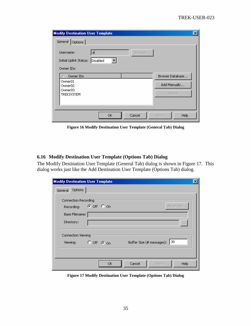
TREK-USER-023
35
Figure 16 Modify Destination User Template (General Tab) Dialog
6.16 Modify Destination User Template (Options Tab) Dialog
The Modify Destination User Template (General Tab) dialog is shown in Figure 17. This
dialog works just like the Add Destination User Template (Options Tab) dialog.
Figure 17 Modify Destination User Template (Options Tab) Dialog
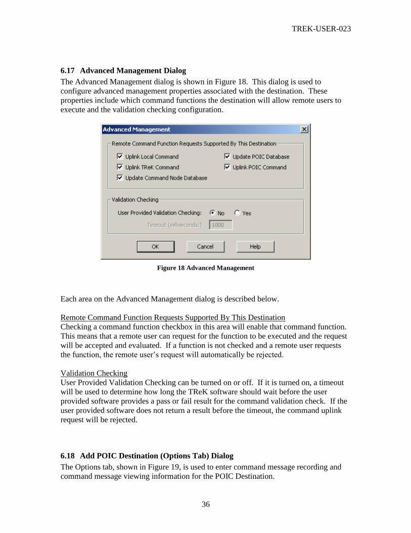
TREK-USER-023
36
6.17 Advanced Management Dialog
The Advanced Management dialog is shown in Figure 18. This dialog is used to
configure advanced management properties associated with the destination. These
properties include which command functions the destination will allow remote users to
execute and the validation checking configuration.
Figure 18 Advanced Management
Each area on the Advanced Management dialog is described below.
Remote Command Function Requests Supported By This Destination
Checking a command function checkbox in this area will enable that command function.
This means that a remote user can request for the function to be executed and the request
will be accepted and evaluated. If a function is not checked and a remote user requests
the function, the remote user’s request will automatically be rejected.
Validation Checking
User Provided Validation Checking can be turned on or off. If it is turned on, a timeout
will be used to determine how long the TReK software should wait before the user
provided software provides a pass or fail result for the command validation check. If the
user provided software does not return a result before the timeout, the command uplink
request will be rejected.
6.18 Add POIC Destination (Options Tab) Dialog
The Options tab, shown in Figure 19, is used to enter command message recording and
command message viewing information for the POIC Destination.
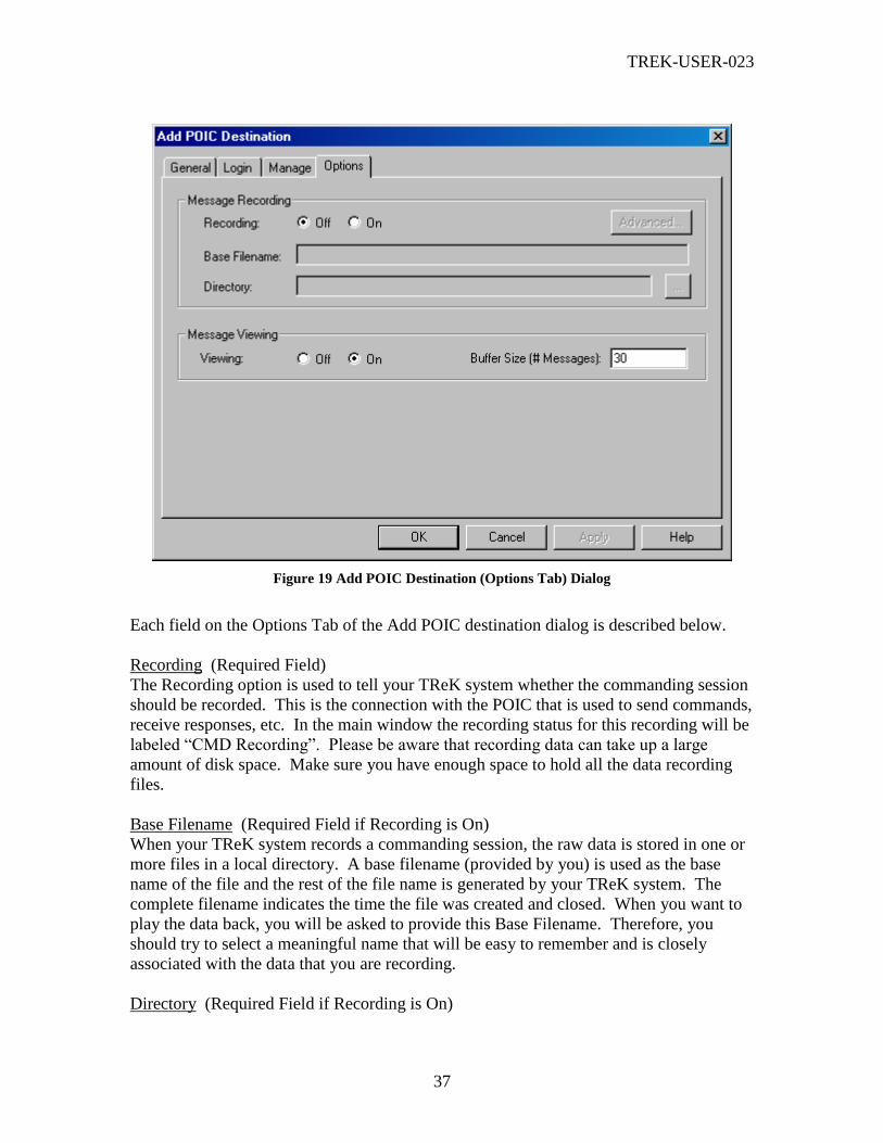
TREK-USER-023
37
Figure 19 Add POIC Destination (Options Tab) Dialog
Each field on the Options Tab of the Add POIC destination dialog is described below.
Recording (Required Field)
The Recording option is used to tell your TReK system whether the commanding session
should be recorded. This is the connection with the POIC that is used to send commands,
receive responses, etc. In the main window the recording status for this recording will be
labeled “CMD Recording”. Please be aware that recording data can take up a large
amount of disk space. Make sure you have enough space to hold all the data recording
files.
Base Filename (Required Field if Recording is On)
When your TReK system records a commanding session, the raw data is stored in one or
more files in a local directory. A base filename (provided by you) is used as the base
name of the file and the rest of the file name is generated by your TReK system. The
complete filename indicates the time the file was created and closed. When you want to
play the data back, you will be asked to provide this Base Filename. Therefore, you
should try to select a meaningful name that will be easy to remember and is closely
associated with the data that you are recording.
Directory (Required Field if Recording is On)

TREK-USER-023
38
The Directory information is used to tell your TReK system which directory should be
used when storing your data recording files. When you want to play the data back, you
will be asked to provide this Directory information so your TReK system can find the
files. This field requires a complete directory path. An example of this is
c:\MyRecordingFiles\. If you don’t like to type or you need help defining the
complete path, you can push the … (dot dot dot) button located to the right of the
Directory field. This will bring up a Windows Browse for Folder dialog which you can
use to identify the local directory path where you want to store your recorded data files.
The Browse for Folder dialog is not described in this document since it is a typical
Windows dialog box. If you need help with this dialog, please refer to your Windows on-
line help.
Viewing (Required Field)
The Viewing option is used to tell your TReK system whether the realtime messages
associated with the commanding session should be available for viewing. Viewing does
use CPU and memory resources. Therefore, remember that if you start to run low on
resources it is possible to turn viewing off.
Buffer Size (# Messages) (Required if Viewing is On)
The Buffer Size tells your TReK system how many realtime messages to store in memory
at a time. The buffer will wrap and older messages will be overwritten. This is a
safeguard against using up too much memory.
Important Note: Don’t get confused between ERIS Recording and Commanding Recording.
Remember that to communicate with the POIC, TReK has to establish two different
connections with the POIC. One is an ERIS connection and one is a commanding connection.
Since these are two different connections, it is possible to specify different recording
preferences for each connection. That’s why you have ERIS Recording and Commanding
Recording. This is also true for Viewing realtime messages. There are realtime ERIS
messages and realtime commanding messages. For more information please reference the
TReK Commanding Tutorial (TREK-USER-020) and/or the POIC to Generic User Interface
Definition Document (SSP-50305).
6.19 Add EXPRESS Destination (General Tab) Dialog
The Add EXPRESS Destination dialog is shown in Figure 20. This dialog is used to add
an EXPRESS Destination to the destination list in the main window. This is how you tell
TReK the information it needs to send commands to a payload in an EXPRESS Rack.
There are four tabs in the Add EXPRESS Destination dialog. Each one is described
below.

TREK-USER-023
39
Figure 20 Add EXPRESS Destination (General Tab) Dialog
Each field on the General Tab of the Add EXPRESS Destination dialog is described
below.
Name (Required Field)
This is the name of the destination. This name must be unique among all destinations
and login sessions.
Database (Required Field)
The database field is used to tell your TReK system which database to use when
gathering command information. The database field must contain the complete directory
path and name for your database. An example of this is
c:\TReK\database\CommandDatabase.mdb. If you don’t know the complete path,
you can push the Browse… button located to the right of the Database field. This will
bring up a Windows Open dialog box that you can use to search local directories to find
your database file. The Open dialog is not described in this document since it is a typical
Windows dialog box. If you need help with this dialog, please refer to the Windows on-
line help. The Open dialog will default to the <base_path>\command_database
directory. The <base_path> for a Windows 2000 system is:
<base_path> = C:\Documents and Settings\<username>\Application Data\TReK
If you would like to configure TReK to use a different default directory, you can set this
property using the Set Command Processing Options dialog. You can save your database

TREK-USER-023
40
files anywhere you like, but a default directory provides an easy way for you to keep up
with your files.
Local IP Address (Required Field)
The Local IP address information is used to set up network services to communicate with
the EXPRESS Rack.
Local Port (Required Field)
The Port Number is used to tell your TReK system which port to use when setting up
network services to communicate with the EXPRESS Rack.
EXPRESS IP Address (Required Field)
The IP Address of the EXPRESS Rack.
EXPRESS Port (Required Field)
The Port Number of the EXPRESS Rack.
6.20 Add EXPRESS Destination (Commands Tab) Dialog
The Commands Tab of the Add EXPRES Destination dialog, shown in Figure 21, is used
to identify the list of commands that you would like to be available to send to the
EXPRESS Rack. You must add all the commands before you activate the destination.
Once the destination is active, you will not be able to add more commands.
Figure 21 Add EXPRESS Destination (Commands Tab) Dialog

TREK-USER-023
41
Dialog Buttons
There are several non-standard buttons on the Add EXPRESS Destination (Commands
Tab) dialog. Each is described below.
Add
Displays the Add Commands dialog that can be used to add commands to the list.
Delete
Deletes the selected commands. You can select one or more commands to delete.
Filter
The Filter button along with the Filter field and Filter By radio buttons provide a way to
filter the list of commands. The Filter By radio buttons are used to indicate which
column to use for the filter. The Filter field is used to specify the filter criteria. If you
leave the Filter field blank all commands will be listed. If you put a * in the Filter field
all commands will be listed. The * character can be used to match one or more characters
and the ? character can be used to match a single character. For example
COMMAND_1* means match all the commands that begin with the characters
COMMAND_1. COMMAND_1?1 means match all the commands that begin with the
characters COMMAND_1, followed by a single character, followed by the character 1.
Note: When a filter has two or more * characters, only the first * character will be
interpreted as zero or more characters. The 2nd
, 3rd
, etc. instances of * will be interpreted
as a literal * character. Since most of the name fields (Command, etc.) that you can filter
against do not support * as a valid character, your filter will return no items in the list if it
has more than one * character.
You can enter more than one ? character in a filter and each of them will be interpreted as
any single character. However, all ? characters after the first * character are interpreted
as literal ? characters.
6.21 Add Commands Dialog
The Add Commands dialog is shown in Figure 22. This dialog is used to add commands
to the Commands List in the Commands Tab of the Add EXPRESS Destination dialog.
The database cannot be entered in this dialog. The database is the one that was identifed
on the General Tab of the Add EXPRESS Destination dialog.

TREK-USER-023
42
Figure 22 Add Commands Dialog
Dialog Buttons
There are several non-standard buttons on the Add Commands dialog. Each is described
below.
Search
The Search button along with the Filter field and Filter By radio buttons provide a way to
filter the list of commands. The Filter By radio buttons are used to indicate which
column to use for the filter. The Filter field is used to specify the filter criteria. If you
leave the Filter field blank all commands will be listed. If you put a * in the Filter field
all commands will be listed. The * character can be used to match one or more characters
and the ? character can be used to match a single character. For example
COMMAND_1* means match all the commands that begin with the characters
COMMAND _1. COMMAND_1?1 means match all the commands that begin with the
characters COMMAND _1, followed by a single character, followed by the character 1.
Note: When a filter has two or more * characters, only the first * character will be
interpreted as zero or more characters. The 2nd
, 3rd
, etc. instances of * will be interpreted
as a literal * character. Since most of the name fields (Command, etc.) that you can filter
against do not support * as a valid character, your filter will return no items in the list if it
has more than one * character.
You can enter more than one ? character in a filter and each of them will be interpreted as
any single character. However, all ? characters after the first * character are interpreted
as literal ? characters.

TREK-USER-023
43
6.22 Add EXPRESS Destination (Manage Tab) Dialog
The Add EXPRESS Destination Manage tab is used to configure the EXPRESS
destination so it can be used by remote users. This tab is similar in appearance and
function to the Add POIC Destination Manage tab. Please reference the Add POIC
Destination (Manage Tab) Dialog section for information about this tab.
6.23 Add EXPRESS Destination (Options Tab) Dialog
The Options tab, shown in Figure 23, is used to enter command message recording and
command message viewing information for the EXPRESS Destination.
Figure 23 Add EXPRESS Destination (Options Tab) Dialog
Each field on the Options Tab of the Add EXPRESS Destination dialog is described
below.
Recording (Required Field)
The Recording option is used to tell your TReK system whether the commanding session
should be recorded. In the main window the recording status for this recording will be
labeled “CMD Recording”. Please be aware that recording data can take up a large
amount of disk space. Make sure you have enough space to hold all the data recording
files.
Base Filename (Required Field if Recording is On)
When your TReK system records a commanding session, the raw data is stored in one or
more files in a local directory. A base filename (provided by you) is used as the base
name of the file and the rest of the file name is generated by your TReK system. The
complete filename indicates the time the file was created and closed. When you want to

TREK-USER-023
44
play the data back, you will be asked to provide this Base Filename. Therefore, you
should try to select a meaningful name that will be easy to remember and is closely
associated with the data that you are recording.
Directory (Required Field if Recording is On)
The Directory information is used to tell your TReK system which directory should be
used when storing your data recording files. When you want to play the data back, you
will be asked to provide this Directory information so your TReK system can find the
files. This field requires a complete directory path. An example of this is
c:\MyRecordingFiles\. If you don’t like to type or you need help defining the
complete path, you can push the … (dot dot dot) button located to the right of the
Directory field. This will bring up a Windows Browse for Folder dialog which you can
use to identify the local directory path where you want to store your recorded data files.
The Browse for Folder dialog is not described in this document since it is a typical
Windows dialog box. If you need help with this dialog, please refer to your Windows on-
line help.
Viewing (Required Field)
The Viewing option is used to tell your TReK system whether the realtime messages
associated with the commanding session should be available for viewing. Viewing does
use CPU and memory resources. Therefore, remember that if you start to run low on
resources it is possible to turn viewing off.
Buffer Size (# Messages) (Required if Viewing is On)
The Buffer Size tells your TReK system how many realtime messages to store in memory
at a time. The buffer will wrap and older messages will be overwritten. This is a
safeguard against using up too much memory.
6.24 Add Suitcase Simulator Destination (General Tab) Dialog
The Add Suitcase Simulator Destination dialog is shown in Figure 24. This dialog is
used to add a Suitcase Simulator Destination to the destination list in the main window.
This is how you tell TReK the information it needs to send commands to a Suitcase
Simulator system. There are four tabs in the Add Suitcase Simulator Destination dialog.
Each one is described below.

TREK-USER-023
45
Figure 24 Add Suitcase Simulator Destination (General Tab) Dialog
Each field on the General Tab of the Add Suitcase Simulator Destination dialog is
described below.
Name (Required Field)
This is the name of the destination. This name must be unique among all destinations
and login sessions.
Database (Required Field)
The database field is used to tell your TReK system which database to use when
gathering command information. The database field must contain the complete directory
path and name for your database. An example of this is
c:\TReK\database\CommandDatabase.mdb. If you don’t know the complete path,
you can push the Browse… button located to the right of the Database field. This will
bring up a Windows Open dialog box that you can use to search local directories to find
your database file. The Open dialog is not described in this document since it is a typical
Windows dialog box. If you need help with this dialog, please refer to the Windows on-
line help. The Open dialog will default to the <base_path>\command_database
directory. The <base_path> for a Windows 2000 system is:
<base_path> = C:\Documents and Settings\<username>\Application Data\TReK
If you would like to configure TReK to use a different default directory, you can set this
property using the Set Command Processing Options dialog. You can save your database
files anywhere you like, but a default directory provides an easy way for you to keep up
with your files.
TREK-USER-023
46
Local IP Address (Required Field)
The Local IP address information is used to set up network services to communicate with
the Suitcase Simulator system.
Local Port (Required Field)
The Port Number is used to tell your TReK system which port to use when setting up
network services to communicate with the Suitcase Simulator system.
SCS IP Address (Required Field)
The IP Address of the Suitcase Simulator System.
SCS Port (Required Field)
The Port Number of the Suitcase Simulator System.
Connecting To (Required Field)
Connecting To – Indicates the version of software running on the Suitcase Simulator.
Background: In Suitcase Simulators running a software load prior to software load SR1,
there is an error on the Suitcase Simulator side that causes TReK commands to be
rejected. This problem was identified in February 2002 and involves the calculation of the
checksum for the command data. TReK calculates the checksum as the sum of 16-bit words
beginning with the CCSDS header and ending with the last word of the actual command.
When the Suitcase Simulator receives the command from TReK, it calculates the checksum
into a 16-bit value by adding all of the bytes received (including the checksum TReK
calculated). This checksum is compared to a word in the packet that is not always at the
end of the CCSDS packet. In both cases, the Suitcase Simulator rejects the command
because of an invalid checksum. When this problem was discovered in February 2002, the
TReK team released a TReK software patch that contained a work-around for the problem.
This work-around involves TReK using an unused data field in the CCSDS header to trick the
Suitcase Simulator into calculating the correct checksum so that it will match the checksum
that TReK sends and will therefore accept the command. The checksum is also placed
within the CCSDS packet as necessary to match where the Suitcase Simulator looks for the
checksum. With the release of Suitcase Simulator software load SR1, the Suitcase
Simulator software problem was fixed. Since its possible that you may have a Suitcase
Simulator with or without the fix, TReK is now configured to work with either one.
6.25 Add Suitcase Simulator Destination (Commands Tab) Dialog
The Add Suitcase Simulator Destination Commands tab is similar in appearance and
function to the Add EXPRESS Destination Commands tab. Please reference the Add
EXPRESS Destination (Commands Tab) Dialog section for information about this tab.

TREK-USER-023
47
6.26 Add Suitcase Simulator Destination (Manage Tab) Dialog
The Add Suitcase Simulator Destination Manage tab is used to configure the Suitcase
Simulator destination so it can be used by remote users. This tab is similar in appearance
and function to the Add POIC Destination Manage tab. Please reference the Add POIC
Destination (Manage Tab) Dialog section for information about this tab.
6.27 Add Suitcase Simulator Destination (Options Tab) Dialog
The Add Suitcase Simulator Destination Options tab is similar in appearance and
function to the Add EXPRESS Destination Options tab. Please reference the Add
EXPRESS Destination (Options Tab) Dialog section for information about this tab.
6.28 Add PRCU Destination (General Tab) Dialog
The Add PRCU Destination dialog is shown in Figure 25. This dialog is used to add a
PRCU Destination to the destination list in the main window. This is how you tell TReK
the information it needs to send commands to a PRCU system. There are four tabs in the
Add PRCU Destination dialog. Each one is described below.
Figure 25 Add PRCU Destination (General Tab) Dialog
Each field on the General Tab of the Add PRCU Destination dialog is described below.
Name (Required Field)
This is the name of the destination. This name must be unique among all destinations
and login sessions.

TREK-USER-023
48
Database (Required Field)
The database field is used to tell your TReK system which database to use when
gathering command information. The database field must contain the complete directory
path and name for your database. An example of this is
c:\TReK\database\CommandDatabase.mdb. If you don’t know the complete path,
you can push the Browse… button located to the right of the Database field. This will
bring up a Windows Open dialog box that you can use to search local directories to find
your database file. The Open dialog is not described in this document since it is a typical
Windows dialog box. If you need help with this dialog, please refer to the Windows on-
line help. The Open dialog will default to the <base_path>\command_database
directory. The <base_path> for a Windows 2000 system is:
<base_path> = C:\Documents and Settings\<username>\Application Data\TReK
If you would like to configure TReK to use a different default directory, you can set this
property using the Set Command Processing Options dialog. You can save your database
files anywhere you like, but a default directory provides an easy way for you to keep up
with your files.
Local IP Address (Required Field)
The Local IP address information is used to set up network services to communicate with
the PRCU system.
Local Port (Required Field)
The Port Number is used to tell your TReK system which port to use when setting up
network services to communicate with the PRCU system.
PRCU IP Address (Required Field)
The IP Address of the PRCU System.
PRCU Port (Required Field)
The Port Number of the PRCU System.
6.29 Add PRCU Destination (Commands Tab) Dialog
The Add PRCU Destination Commands tab is similar in appearance and function to the
Add EXPRESS Destination Commands tab. Please reference the Add EXPRESS
Destination (Commands Tab) Dialogsection for information about this tab.
6.30 Add PRCU Destination (Manage Tab) Dialog
The Add PRCU Destination Manage tab is used to configure the PRCU destination so it
can be used by remote users. This tab is similar in appearance and function to the Add
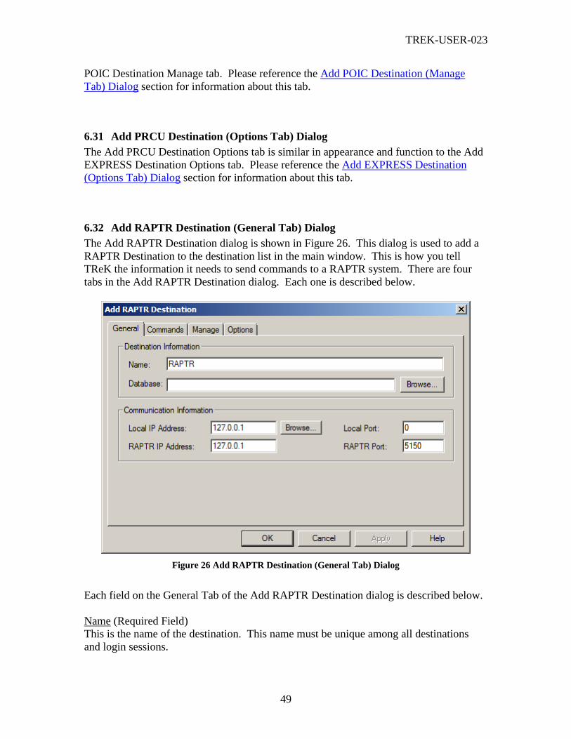
TREK-USER-023
49
POIC Destination Manage tab. Please reference the Add POIC Destination (Manage
Tab) Dialog section for information about this tab.
6.31 Add PRCU Destination (Options Tab) Dialog
The Add PRCU Destination Options tab is similar in appearance and function to the Add
EXPRESS Destination Options tab. Please reference the Add EXPRESS Destination
(Options Tab) Dialog section for information about this tab.
6.32 Add RAPTR Destination (General Tab) Dialog
The Add RAPTR Destination dialog is shown in Figure 26. This dialog is used to add a
RAPTR Destination to the destination list in the main window. This is how you tell
TReK the information it needs to send commands to a RAPTR system. There are four
tabs in the Add RAPTR Destination dialog. Each one is described below.
Figure 26 Add RAPTR Destination (General Tab) Dialog
Each field on the General Tab of the Add RAPTR Destination dialog is described below.
Name (Required Field)
This is the name of the destination. This name must be unique among all destinations
and login sessions.

TREK-USER-023
50
Database (Required Field)
The database field is used to tell your TReK system which database to use when
gathering command information. The database field must contain the complete directory
path and name for your database. An example of this is
c:\TReK\database\CommandDatabase.mdb. If you don’t know the complete path,
you can push the Browse… button located to the right of the Database field. This will
bring up a Windows Open dialog box that you can use to search local directories to find
your database file. The Open dialog is not described in this document since it is a typical
Windows dialog box. If you need help with this dialog, please refer to the Windows on-
line help. The Open dialog will default to the <base_path>\command_database
directory. The <base_path> for a Windows 2000 system is:
<base_path> = C:\Documents and Settings\<username>\Application Data\TReK
If you would like to configure TReK to use a different default directory, you can set this
property using the Set Command Processing Options dialog. You can save your database
files anywhere you like, but a default directory provides an easy way for you to keep up
with your files.
Local IP Address (Required Field)
The Local IP address information is used to set up network services to communicate with
the RAPTR system.
Local Port (Required Field)
The Port Number is used to tell your TReK system which port to use when setting up
network services to communicate with the RAPTR system.
RAPTR IP Address (Required Field)
The IP Address of the RAPTR System.
RAPTR Port (Required Field)
The Port Number of the RAPTR System.
6.33 Add RAPTR Destination (Commands Tab) Dialog
The Add RAPTR Destination Commands tab is similar in appearance and function to the
Add EXPRESS Destination Commands tab. Please reference the Add EXPRESS
Destination (Commands Tab) Dialog section for information about this tab.
6.34 Add RAPTR Destination (Manage Tab) Dialog
The Add RAPTR Destination Manage tab is used to configure the RAPTR destination so
it can be used by remote users. This tab is similar in appearance and function to the Add

TREK-USER-023
51
POIC Destination Manage tab. Please reference the Add POIC Destination (Manage
Tab) Dialog section for information about this tab.
6.35 Add RAPTR Destination (Options Tab) Dialog
The Add RAPTR Destination Options tab is similar in appearance and function to the
Add EXPRESS Destination Options tab. Please reference the Add EXPRESS
Destination (Options Tab) Dialog section for information about this tab.
6.36 Add TReK Destination (General Tab) Dialog
The Add TReK Destination (General Tab) dialog is shown in Figure 27. This dialog is
used to establish a command session with another TReK system. The Add TReK
Destination dialog is very similar to the Add POIC Destination Dialog. A POIC
destination has two connections – an ERIS login session and a POIC command
connection. The same idea applies to a TReK destination. A TReK destination has a
TReK Login Session and a TReK command connection. The TReK Destination has four
tabs when it is inactive as shown in Figure 27. It has seven tabs when it is active. The
POIC Configuration tab, the POIC Status tab, and the TReK Status tab are added once
the destination is active. For details about the controls on this tab please refer to the Add
POIC Destination (General Tab) Dialog section.
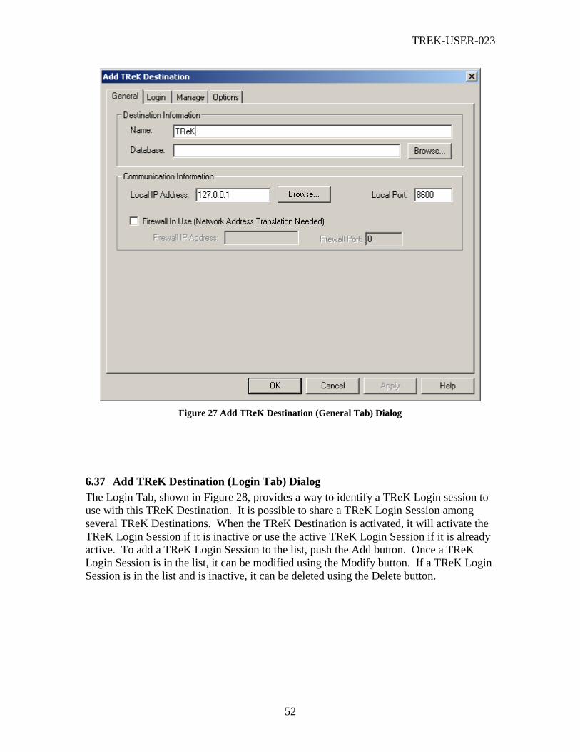
TREK-USER-023
52
Figure 27 Add TReK Destination (General Tab) Dialog
6.37 Add TReK Destination (Login Tab) Dialog
The Login Tab, shown in Figure 28, provides a way to identify a TReK Login session to
use with this TReK Destination. It is possible to share a TReK Login Session among
several TReK Destinations. When the TReK Destination is activated, it will activate the
TReK Login Session if it is inactive or use the active TReK Login Session if it is already
active. To add a TReK Login Session to the list, push the Add button. Once a TReK
Login Session is in the list, it can be modified using the Modify button. If a TReK Login
Session is in the list and is inactive, it can be deleted using the Delete button.

TREK-USER-023
53
Figure 28 Add TReK Destination (Login Tab) Dialog
Note: When you select to Modify a TReK Login Session, the name of the TReK Login
Session cannot be modified (regardless of whether the TReK Login Session is active or
inactive). If you need to change the name, you will need to add a new TReK Login Session.
The old TReK Login Session will be considered “in use” until you leave the dialog. Therefore,
if you want to delete it you need to delete it after you leave this dialog.
Note2: All the TReK Login Session list changes you make on this tab take place immediately
and cannot be cancelled. The only item on this tab that can be cancelled is the TReK Login
Session to be used by this destination. If you push the Cancel button to cancel all the
actions taken in the dialog, the TReK Login Session assignment will be reset but the TReK
Login Sessions added, modified, or deleted will not be cancelled or reset.
6.38 Add TReK Login Session (General Tab) Dialog
The Add TReK Login Session dialog is shown in Figure 29. This dialog is used to add a
TReK Login Session to the TReK Login Session list in the Login Tab of the Add TReK
Destination dialog. It has a General tab and an Options tab.

TREK-USER-023
54
Figure 29 Add TReK Login Session Dialog
Each field and control on the Add TReK Login Session (General Tab) dialog is described
below.
Name
This is the name of the TReK Login Session. This name must be unique among all
destinations and login sessions.
Remote TReK IP Address
The IP Address of the remote TReK system you want to connect to.
Remote TReK Port
The Port Number of the remote TReK system you want to connect to.
Username
The username for your TReK user account on the remote TReK system. This is not an
operating system user account. This is the TReK user account that was created in the
Remote Services application on the remote TReK system. This should be provided to
you by the owner of the remote TReK system. If you leave this field blank you will be
prompted to enter this information when you activate this destination. (During the
activation sequence when your TReK system is establishing a connection with the remote
TReK system, the remote TReK’s remote services application will prompt you to log in
to your TReK user account).
Password

TREK-USER-023
55
The password for your TReK User Account. This should be provided to you by the
owner of the remote TReK system. If you save your configuration, the password will not
be saved in the configuration file. This has been done for security reasons.
6.39 Add TReK Login Session (Options Tab) Dialog
The Add TReK Login Session Options Tab is shown in Figure 30. This tab is used to
configure recording and viewing properties for the TReK Login Session. This tab is very
similar to the Add ERIS Login Session Options Tab. Please reference the Add ERIS
Login Session (Options Tab) Dialog section for details about the controls on this tab.
Figure 30 Add TReK Login Session (Options Tab) Dialog
6.40 Add TReK Destination (Manage Tab) Dialog
The Add TReK Destination Manage tab is used to configure the TReK destination so it
can be used by remote users. This tab is similar in appearance and function to the Add
POIC Destination Manage tab. Please reference the Add POIC Destination (Manage
Tab) Dialog section for information about this tab.
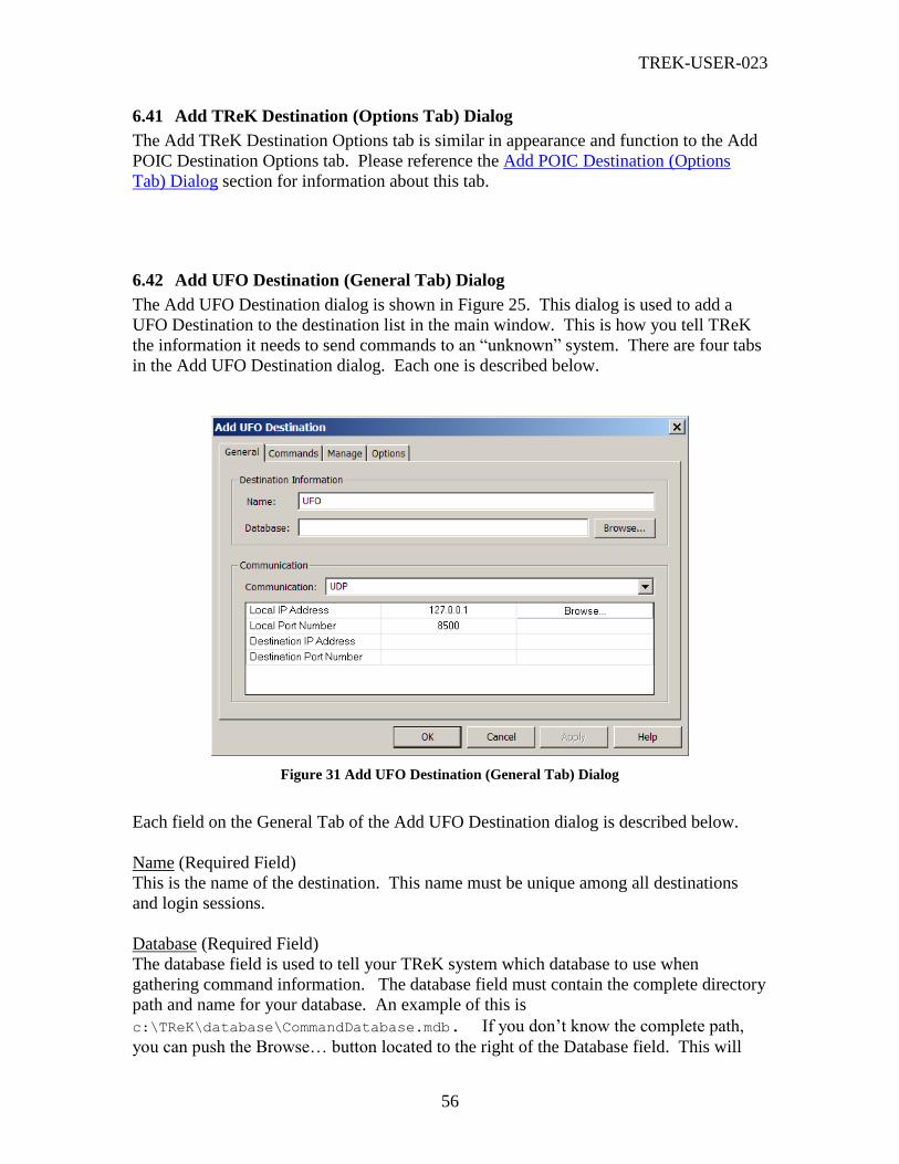
TREK-USER-023
56
6.41 Add TReK Destination (Options Tab) Dialog
The Add TReK Destination Options tab is similar in appearance and function to the Add
POIC Destination Options tab. Please reference the Add POIC Destination (Options
Tab) Dialog section for information about this tab.
6.42 Add UFO Destination (General Tab) Dialog
The Add UFO Destination dialog is shown in Figure 25. This dialog is used to add a
UFO Destination to the destination list in the main window. This is how you tell TReK
the information it needs to send commands to an “unknown” system. There are four tabs
in the Add UFO Destination dialog. Each one is described below.
Figure 31 Add UFO Destination (General Tab) Dialog
Each field on the General Tab of the Add UFO Destination dialog is described below.
Name (Required Field)
This is the name of the destination. This name must be unique among all destinations
and login sessions.
Database (Required Field)
The database field is used to tell your TReK system which database to use when
gathering command information. The database field must contain the complete directory
path and name for your database. An example of this is
c:\TReK\database\CommandDatabase.mdb. If you don’t know the complete path,
you can push the Browse… button located to the right of the Database field. This will
TREK-USER-023
57
bring up a Windows Open dialog box that you can use to search local directories to find
your database file. The Open dialog is not described in this document since it is a typical
Windows dialog box. If you need help with this dialog, please refer to the Windows on-
line help. The Open dialog will default to the <base_path>\command_database
directory. The <base_path> for a Windows 2000 system is:
<base_path> = C:\Documents and Settings\<username>\Application Data\TReK
If you would like to configure TReK to use a different default directory, you can set this
property using the Set Command Processing Options dialog. You can save your database
files anywhere you like, but a default directory provides an easy way for you to keep up
with your files.
Communication (Required Field)
The communication section specifies the type of communication mechanism and
associated properties to use when interfacing with the “unknown” system.
6.43 Add UFO Destination (Commands Tab) Dialog
The Add PRCU Destination Commands tab is similar in appearance and function to the
Add EXPRESS Destination Commands tab. Please reference the Add EXPRESS
Destination (Commands Tab) Dialog section for information about this tab.
6.44 Add UFO Destination (Manage Tab) Dialog
The Add PRCU Destination Manage tab is used to configure the PRCU destination so it
can be used by remote users. This tab is similar in appearance and function to the Add
POIC Destination Manage tab. Please reference the Add POIC Destination (Manage
Tab) Dialog section for information about this tab.
6.45 Add UFO Destination (Options Tab) Dialog
The Add PRCU Destination Options tab is similar in appearance and function to the Add
EXPRESS Destination Options tab. Please reference the Add EXPRESS Destination
(Options Tab) Dialog section for information about this tab.
6.46 Login Dialog
The Login dialog is shown in Figure 32. This dialog is used to login to an external
system such as the POIC or another TReK system. The POIC login requires a username,
password, and passcode. The TReK login only requires a username and password.

TREK-USER-023
58
Unless you enter the login information (Username and Password) when you create the
login session, you will always be prompted with this dialog when connecting to the
external system. Even if you are using a configuration file and you saved your
configuration you will still be prompted. This is because password information is not
saved in configuration files for security reasons. Therefore, you will always be prompted
to enter it. (Note: The title of the Login dialog is < Login Session Name> Login. Since
you can set up multiple Login Sessions, the title shows which Login Session you are
using to login.)
Figure 32 Login Dialog
Each field on the Login dialog is described below.
Username (Required Field)
The username for your POIC or TReK user account (or a username that is applicable for
the TReK Command Trainer if you are using the Command Trainer application).
Password (Required Field)
The password for your POIC or TReK user account (or a password that is applicable for
the TReK Command Trainer if you are using the Command Trainer application).
Passcode (Required Field for POIC)
The passcode for your POIC user account (or a passcode that is applicable for the TReK
Command Trainer if you are using the Command Trainer application). The TReK login
does not require a passcode.
The TReK Command Trainer application accepts the following username/password
combinations:
Username Password Passcode
captain kirk 12345678
spock science 12345678
mccoy bones 12345678
a b 12345678

TREK-USER-023
59
6.47 Change Password Dialog
The Change Password dialog is shown in Figure 33. This dialog is used to change your
POIC account password. If your POIC account password has expired, this dialog will be
displayed during the login process when you are establishing an ERIS session. You can
also request to change your password. You can do this by using the Change Password
button on the ERIS Sessions dialog. The change password feature is only available when
you have an active ERIS session.
Figure 33 Change Password Dialog
Each field on the Change Password dialog is described below.
Old Password (Required Field)
The old password associated with your POIC account.
New Password (Required Field)
The new password you would like to assign to your POIC account.
Confirm New Password (Required Field)
The new password you would like to assign to your POIC account. This should match
the password you entered in the New Password field.
6.48 Select MOP Dialog
The Select MOP dialog is shown in Figure 34. This dialog is used to select a POIC
Mission/Operational Support Mode/ Project (MOP) when logging in to the POIC. If you
save your configuration, the MOP will be saved in the configuration file. The Select
MOP dialog may or may not be displayed during the login sequence when activating a
POIC destination. Section 6.7 provides information that explains when you will be
prompted to select a MOP.

TREK-USER-023
60
Figure 34 Select MOP Dialog
6.49 Select Role Dialog
The Select Role dialog is shown in Figure 35. This dialog is used to select a POIC Role
when logging in to the POIC. If you save your configuration, the Role will be saved in
the configuration file. The Select Role dialog will always be displayed during the login
sequence when activating a POIC destination.
Figure 35 Select Role Dialog
6.50 POIC Warning Banner Dialog
When you log into the POIC, the POIC Warning Banner dialog shown in Figure 36 will
be displayed. You must push the OK button to acknowledge that you are logging into a
government computer to log in successfully.

TREK-USER-023
61
Figure 36 POIC Warning Banner Dialog
6.51 Select Destination Dialog
The Select Destination dialog is shown in Figure 37. This dialog is used to select a
destination when logging in to a TReK system (Command Node). If you save your
configuration, the destination will not be saved in the configuration file.
Figure 37 Select Destination Dialog
6.52 Browse For IP Address Dialog
The Browse For IP Address dialog is shown in Figure 38. This dialog is used to search a
TReK system for all IP addresses or network cards associated with the system.

TREK-USER-023
62
Figure 38 Browse For IP Address Dialog
Each field in the Browse For IP Address dialog is described below.
Please select an IP Address: (Required Field)
You have two options when choosing an IP address. If your TReK system does not have
network connectivity (such as no ethernet card or modem or the system is not connected
to a network), you need to use the standard loopback address (127.0.0.1). This option is
provided by choosing the “Loopback Address: 127.0.0.1” radio button. Users with one or
more network cards will need to choose which network card or IP Address they would
like to use. Choosing the “IP Address List” radio button provides this option. The user
must then select an IP address from the list.
IP Address
The IP Address field is filled in when you select the Loopback IP address or an IP
Address in the list. The IP Address will be copied to the dialog box that contained the
button you used to bring up the Browse For IP Address dialog.
6.53 Enter Recording Information
The Enter Recording Information dialog is shown in Figure 39. This dialog will appear
when you select Start ERIS Recording or Start Commanding Recording from the
Destination List pop-up menu. You use this dialog to tell your TReK system where you
want to store your recording files and what you want to use for the Base Filename.
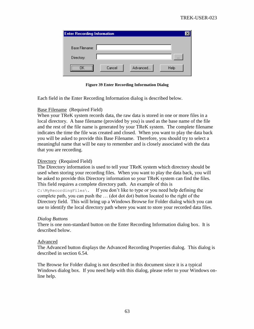
TREK-USER-023
63
Figure 39 Enter Recording Information Dialog
Each field in the Enter Recording Information dialog is described below.
Base Filename (Required Field)
When your TReK system records data, the raw data is stored in one or more files in a
local directory. A base filename (provided by you) is used as the base name of the file
and the rest of the file name is generated by your TReK system. The complete filename
indicates the time the file was created and closed. When you want to play the data back
you will be asked to provide this Base Filename. Therefore, you should try to select a
meaningful name that will be easy to remember and is closely associated with the data
that you are recording.
Directory (Required Field)
The Directory information is used to tell your TReK system which directory should be
used when storing your recording files. When you want to play the data back, you will
be asked to provide this Directory information so your TReK system can find the files.
This field requires a complete directory path. An example of this is
C:\MyRecordingFiles\. If you don’t like to type or you need help defining the
complete path, you can push the … (dot dot dot) button located to the right of the
Directory field. This will bring up a Windows Browse for Folder dialog which you can
use to identify the local directory path where you want to store your recorded data files.
Dialog Buttons
There is one non-standard button on the Enter Recording Information dialog box. It is
described below.
Advanced
The Advanced button displays the Advanced Recording Properties dialog. This dialog is
described in section 6.54.
The Browse for Folder dialog is not described in this document since it is a typical
Windows dialog box. If you need help with this dialog, please refer to your Windows on-
line help.

TREK-USER-023
64
6.54 Advanced Recording Dialog
The Advanced Recording dialog is shown in Figure 40. This dialog will appear when
you select the Advanced button located next to a Message Recording option. You use
this dialog to tell your TReK system what recording properties to use for a particular
message recording activity.
Figure 40 Advanced Recording Dialog
Maximum File Size (bytes) (Required Field)
The Maximum File Size information is used to determine when to close a recording file.
This property is always used.
Maximum Time File Is Open (minutes)
The Maximum Time File Is Open Checkbox is used to indicate whether the file should be
closed based on a maximum time. This is an optional property. If you check the
checkbox then this property will be used. If you check the box, then you must also fill in
the text field with the amount of time in minutes that should be used as the maximum
time. The Maximum Time File Is Open property is used in addition to the Maximum File
Size property. If the maximum size is reached before the maximum time, then the file
will be closed based on the size. However, if the maximum time is reached before the
maximum size is reached, the file will be closed based on the maximum time.
Maximum Time Directory Is Open
The Maximum Time Directory Is Open Checkbox is used to indicate whether recording
files should be placed in sub-directories within the parent base directory. The directories
will be open/closed based on Day, Week, Month, or Year. This is an optional property.
If you check the checkbox then this property will be used.
6.55 View Realtime Login Messages (destination_name) Dialog
The View Realtime Login Messages dialog is shown in Figure 41. This dialog displays
the realtime messages that were sent back and forth between TReK and an external
system for a specific Login Session.

TREK-USER-023
65
Figure 41 View Realtime Login Messages (destination_name) Dialog
Dialog Buttons
There are several non-standard buttons on the View Realtime Login Messages dialog
box. Each is described below.
Pause
The Pause button will pause the display of any incoming messages. Since the realtime
messages are stored in a buffer it is possible for the buffer to wrap while the display is
paused. Therefore, when you push the Resume button you may see some of the messages
that arrived while the display was paused or some may be missing because the buffer
wrapped.
Resume
The Resume button will resume display of any incoming messages.
Clear
The Clear button will clear the display and the underlying buffer where the realtime
messages are stored. Therefore, if you push the Clear button, all the realtime messages
that TReK currently has stored in the buffer and the window will be deleted. However,
any new messages that arrive after you push the clear button will be stored in the buffer
and displayed in the realtime message viewer window. (Note: If you are recording
incoming messages they will always be stored to disk. So even if you push the clear
button in a realtime viewer window this does not affect data that is being recorded to
disk. You can use the Recorded Data Viewer to view messages that have been recorded
in a file.)

TREK-USER-023
66
6.56 View Realtime Commanding Messages (destination_name) Dialog
The View Realtime Commanding Messages dialog is shown in Figure 42. This dialog
displays the realtime commanding messages that were sent back and forth between TReK
and a specific command destination. The messages are formatted to show the TReK
Receipt Time (TRT) associated with the message, the hexadecimal representation of the
message, and other destination/message specific information.
Figure 42 View Realtime Commanding Messages (destination_name) Dialog
Buttons
There are several non-standard buttons on the View Realtime Commanding Messages
dialog box. Each is described below.
Pause
The Pause button will pause the display of any incoming messages. Since the realtime
messages are stored in a buffer it is possible for the buffer to wrap while the display is
paused. Therefore, when you push the Resume button you may see some of the messages
that arrived while the display was paused or some may be missing because the buffer
wrapped.
Resume
The Resume button will resume display of any incoming messages.
Clear
The Clear button will clear the display and the underlying buffer where the realtime
messages are stored. Therefore, if you push the Clear button, all the realtime messages
that TReK currently has stored in the buffer and the window will be deleted. However,
any new messages that arrive after you push the clear button will be stored in the buffer
and displayed in the realtime message viewer window. (Note: If you are recording
incoming messages they will always be stored to disk. So even if you push the clear
button in a realtime viewer window this does not affect data that is being recorded to

TREK-USER-023
67
disk. You can use the Recorded Data Viewer to view messages that have been recorded
in a file.)
6.57 Destination Properties for Destination (destination_name) Dialog
The Destination Properties dialog for a POIC destination is shown in Figure 43, for an
EXRESS Destination in Figure 44, for a Suitcase Simulator destination in Figure 45, for a
PRCU destination in Figure 46, for a RAPTR destination in Figure 47, for a TReK
destination in Figure 48, and for a UFO destination in Figure 49. The Destination
Properties dialog shows all the properties associated with the selected destination. If you
have never activated the destination then you can change any of the destination’s
properties. However, if you have already activated the destination, then some of the
destination’s properties will be insensitive (such as the Database field). The Destination
Properties dialog contains the same tabs as those in the Add Destination dialogs.
However, in the case of a POIC or TReK destination there are some additional tabs.
Once a POIC destination is active the destination properties dialog will contain a POIC
Configuration tab as shown in Figure 50 and a POIC Status tab as shown in Figure 51.
These tabs also appear in the Add TReK Destination dialog. Additionally there is also a
TReK Status tab that appears in the TReK Destination Properties dialog.
Figure 43 Destination Properties for (POIC) Destination (destination_name) Dialog
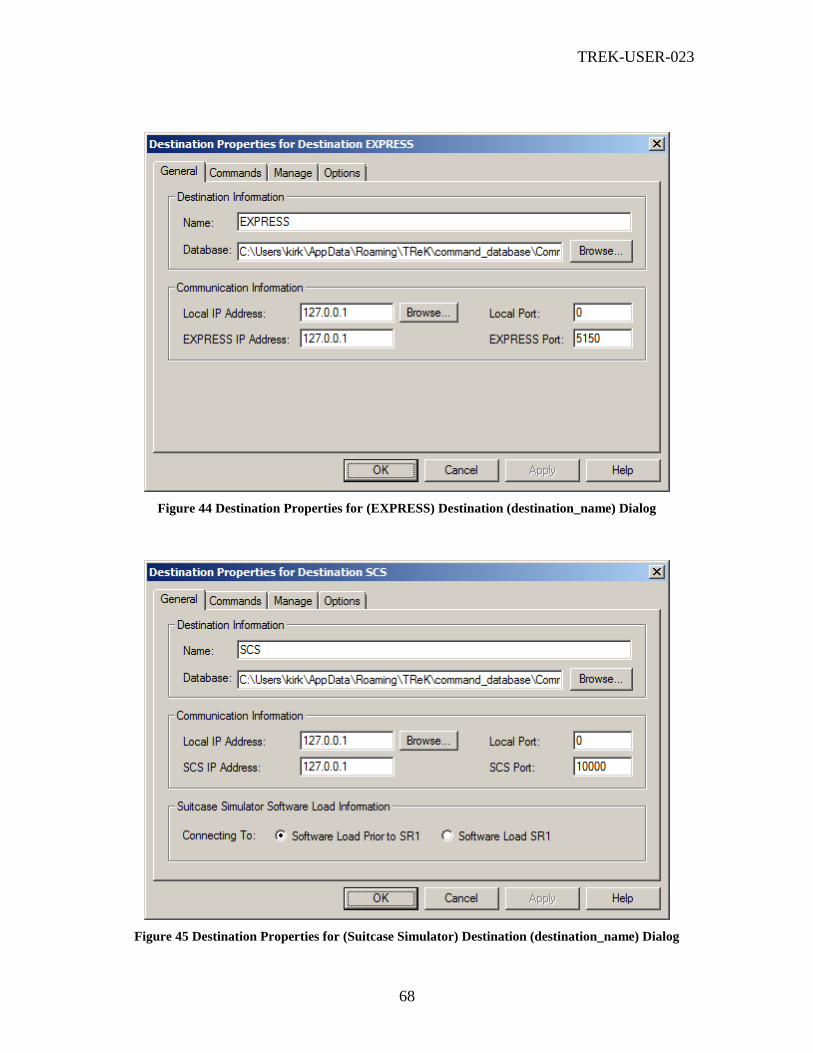
TREK-USER-023
68
Figure 44 Destination Properties for (EXPRESS) Destination (destination_name) Dialog
Figure 45 Destination Properties for (Suitcase Simulator) Destination (destination_name) Dialog
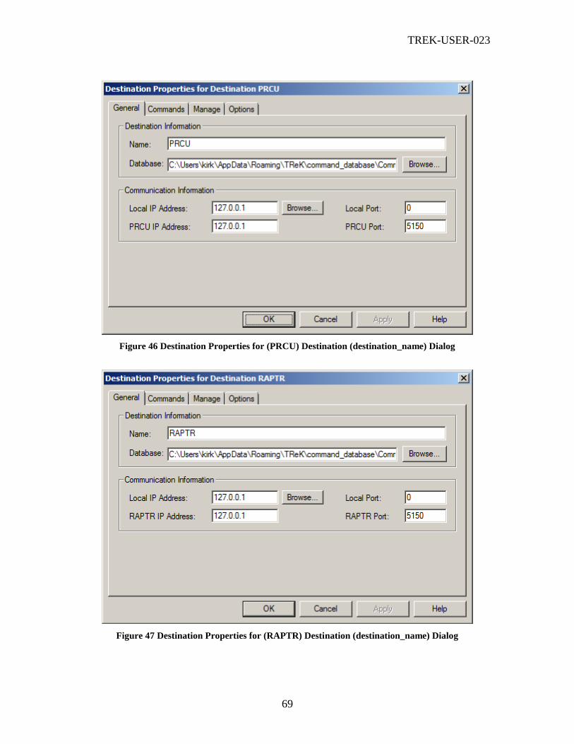
TREK-USER-023
69
Figure 46 Destination Properties for (PRCU) Destination (destination_name) Dialog
Figure 47 Destination Properties for (RAPTR) Destination (destination_name) Dialog

TREK-USER-023
70
Figure 48 Destination Properties for (TReK) Destination (destination_name) Dialog
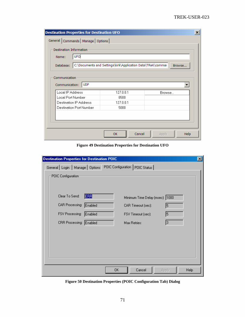
TREK-USER-023
71
Figure 49 Destination Properties for Destination UFO
Figure 50 Destination Properties (POIC Configuration Tab) Dialog
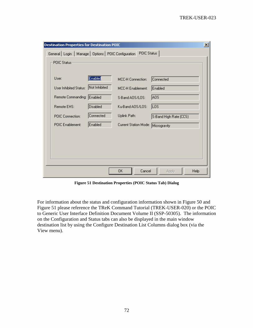
TREK-USER-023
72
Figure 51 Destination Properties (POIC Status Tab) Dialog
For information about the status and configuration information shown in Figure 50 and
Figure 51 please reference the TReK Command Tutorial (TREK-USER-020) or the POIC
to Generic User Interface Definition Document Volume II (SSP-50305). The information
on the Configuration and Status tabs can also be displayed in the main window
destination list by using the Configure Destination List Columns dialog box (via the
View menu).

TREK-USER-023
73
Figure 52 Destination Properties (TReK Status Tab) Dialog
As shown in Figure 52, the TReK Status Tab provides configuration information about
the command connection to the TReK command node. This includes whether the
command node has enabled or disabled remote commanding, whether the command node
has enabled or disabled you as a user, and what command functions are available for you
to use.
6.58 Commands Dialog
The Commands dialog is shown in Figure 53. This dialog lists all the commands that are
associated with each destination. Using this dialog you can uplink commands and
modify the contents of a command either locally or in an external database (such as the
POIC’s database). The command functions available will depend on the destination you
have selected.
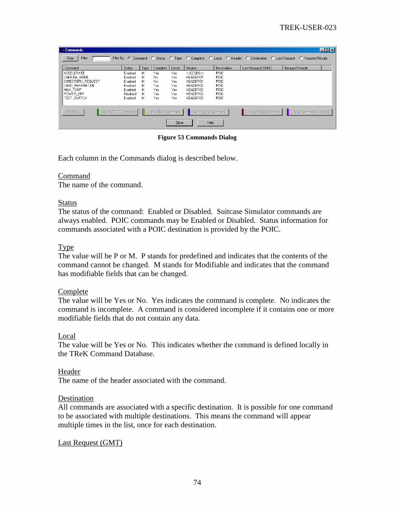
TREK-USER-023
74
Figure 53 Commands Dialog
Each column in the Commands dialog is described below.
Command
The name of the command.
Status
The status of the command: Enabled or Disabled. Suitcase Simulator commands are
always enabled. POIC commands may be Enabled or Disabled. Status information for
commands associated with a POIC destination is provided by the POIC.
Type
The value will be P or M. P stands for predefined and indicates that the contents of the
command cannot be changed. M stands for Modifiable and indicates that the command
has modifiable fields that can be changed.
Complete
The value will be Yes or No. Yes indicates the command is complete. No indicates the
command is incomplete. A command is considered incomplete if it contains one or more
modifiable fields that do not contain any data.
Local
The value will be Yes or No. This indicates whether the command is defined locally in
the TReK Command Database.
Header
The name of the header associated with the command.
Destination
All commands are associated with a specific destination. It is possible for one command
to be associated with multiple destinations. This means the command will appear
multiple times in the list, once for each destination.
Last Request (GMT)

TREK-USER-023
75
Indicates the last request made for that particular command. This may be an Update
request or an Uplink request. Please note that the Last Request information shown in this
dialog is only updated when the request is performed using this dialog. If the request is
performed using a TReK API call, the Last Request information will not be updated.
Request Results
Indicates the results of the last request. This may be Success or an error condition. The
errors shown in this column correspond to TReK Command User API return codes.
Please note that the Request Results information shown in this dialog is only updated
when the request is performed using this dialog. If the request is performed using a
TReK API call the Request Results information will not be updated.
Buttons
There are several non-standard buttons on the Commands dialog. Each is described
below.
Filter
The Filter button along with the Filter field and Filter By radio buttons provide a way to
filter the list of commands. The Filter By radio buttons are used to indicate which
column to use for the filter. The Filter field is used to specify the filter criteria. If you
leave the Filter field blank all commands will be listed. If you put a * in the Filter field
all commands will be listed. The * character can be used to match one or more characters
and the ? character can be used to match a single character. For example
COMMAND_1* means match all the commands that begin with the characters
COMMAND_1. COMMAND_1?1 means match all the commands that begin with the
characters COMMAND_1, followed by a single character, followed by the character 1.
Note: When a filter has two or more * characters, only the first * character will be
interpreted as zero or more characters. The 2nd
, 3rd
, etc. instances of * will be interpreted
as a literal * character. Since most of the name fields (Command, etc.) that you can filter
against do not support * as a valid character, your filter will return no items in the list if it
has more than one * character.
You can enter more than one ? character in a filter and each of them will be interpreted as
any single character . However, all ? characters after the first * character are interpreted
as literal ? characters.
Modify
The Modify button provides access to a dialog that can be used to view or modify
properties associated with the command. The Modify button will only be available when
an item in the list is selected. Even if a command is predefined it is still possible to
modify the command’s description.

TREK-USER-023
76
Uplink POIC Command
When you push the Uplink POIC Command button, TReK submits a request to the POIC
to build the command using the command data stored in the POIC database and then
uplink the command. This option is only available for a command that is associated with
a POIC destination.
Uplink TReK Command
When you push the Uplink TReK Command button, TReK submits a request to the
remote TReK system (a TReK command node) to build the command uplink pattern
using the command data stored in the command node’s database and then send the uplink
pattern to the command node’s destination. This option is only available for a command
that is associated with a TReK destination.
Uplink Local Command
When you push the Uplink Local Command button, TReK uses the command data stored
in the local TReK database to build the command uplink pattern and then send the uplink
pattern to the destination. This option is only available for a command that is defined
locally in the TReK Command Database.
Note: In the case of a POIC destination, the POIC calls this type of command request a
remotely generated command request.
Update POIC Command
When you push the Update POIC Command button, TReK submits a request to the POIC
to update the contents of the command in the POIC database with the contents of the
command that are stored in the local TReK database. This option is only available for a
command that is associated with a POIC destination that contains modifiable fields and is
defined locally in the TReK Command Database.
Update Command Node Database
When you push the Update Command Node Database button, TReK submits a request to
the remote TReK system (a TReK command node) to update the contents of the
command in the command node database with the contents of the command that are
stored in the local TReK database. This option is only available for a command that is
associated with a TReK destination that contains modifiable fields and is defined locally
in the TReK Command Database.
6.59 Modify Command Dialog
The Modify Command dialog is shown in Figure 54. This dialog is used to modify the
properties associated with a specific command.

TREK-USER-023
77
Figure 54 Modify Command Dialog
Each field and control on the Modify Command dialog is described below.
Name
The name of the command.
Header Name
The name of the header associated with the command.
Type
The type of command: Predefined or Modifiable.
Complete
The value will be Yes or No. Yes indicates the command is complete. No indicates the
command is incomplete. A command is considered incomplete if it contains one or more
modifiable fields that do not contain any data.
Technical Name
The technical name for the command.
Description
A description of the command.
Command Field List
The command field list shows all the fields contained in the command. Please reference
the TReK Command Database Definition Document (TREK-USER-015) for information
about command fields.

TREK-USER-023
78
Buttons
There is one non-standard button on the Modify Command dialog. It is described below.
Modify Field
The Modify Field button provides access to a dialog that can be used to view or modify
properties associated with the command field. This includes updating the command
field’s value. The Modify button will only be available when an item in the list is
selected. Even if a field is predefined it is still possible to modify the description
associated with the field.
6.60 Modify Command Field Dialog
The Modify Command Field dialog is shown in Figure 55. This dialog is used to modify
the properties associated with a command field.

TREK-USER-023
79
Figure 55 Modify Command Field Dialog
Each field and control on the Modify Command Field dialog is described below.
Field Name
The name of the command field. This field cannot be modified.
Complete
The value will be Yes or No. Yes indicates the command field is complete. No indicates
the command field is incomplete. A command field is considered incomplete if it does
not contain any data.
Field Length
The length of the command field in bits. This field cannot be modified.
Engineering Units
The engineering unit associated with the command field. This field cannot be modified.
Byte Order
Indicates whether the command field’s byte order is no swapping, byte swapped, word
swapped, byte and word swapped, byte reversed, or word reversed. This field cannot be
modified.
Input Data Type
The command field’s input data type. This field cannot be modified.
Uplink Data Type
The command field’s uplink data type. This field cannot be modified.
Type
The type of command field. The value will be P or M. P stands for Predefined and M
stands for Modifiable. This field cannot be modified.
Description
A description of the command field.
Field Value Representation
In some cases it is possible to input the field data using different representations. The
Uplink Data Type is used to determine which representations are valid. The data that
can be entered into the Field Value will depend on the Field Value Representation
selected. For example, if binary is selected then only binary data can be entered into the
Field Value field. The Field Value field units information will reflect which type of data
should be entered.
Field Value

TREK-USER-023
80
The Field Value field is used to update the value of the field. This information can be
entered using different number systems.
Field Values (Binary, Octal, Hexadecimal, Decimal) Group of Fields
These fields are always insensitive and are only used to display data. When you enter
information into the Field Value field, these fields will be updated to reflect the value you
entered after conversion and swapping have been applied. If the value will be calibrated,
these fields will be blank.
Calibrator Type
The command field calibrator’s type. Valid types are: PC (Polynomial Coefficient), PP
(Point Pair), or SC (State Code).
Calibrator Name
The name of the calibrator associated with the command field.
Default Set Number
The default set number. The default set number identifies which set of calibration data to
use.
Tolerance
For integer uplink values to which calibration has been applied, this is the maximum
deviation allowed between the calibrated value and the nearest integer. If no tolerance is
specified for an integer uplink value, then the calibration must result in an integer value.
(Note: The Modify Command Field dialog cannot be used to modify this value.).
6.61 Command Headers Dialog
The Command Headers dialog is shown in Figure 56. When you enter information for a
destination one of the items you identify is a database. When you activate a destination,
all the headers in the database are retrieved. The Command Headers dialog displays all
the headers that were retrieved from each of the databases that you are currently using.
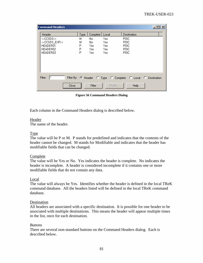
TREK-USER-023
81
Figure 56 Command Headers Dialog
Each column in the Command Headers dialog is described below.
Header
The name of the header.
Type
The value will be P or M. P stands for predefined and indicates that the contents of the
header cannot be changed. M stands for Modifiable and indicates that the header has
modifiable fields that can be changed.
Complete
The value will be Yes or No. Yes indicates the header is complete. No indicates the
header is incomplete. A header is considered incomplete if it contains one or more
modifiable fields that do not contain any data.
Local
The value will always be Yes. Identifies whether the header is defined in the local TReK
command database. All the headers listed will be defined in the local TReK command
database.
Destination
All headers are associated with a specific destination. It is possible for one header to be
associated with multiple destinations. This means the header will appear multiple times
in the list, once for each destination.
Buttons
There are several non-standard buttons on the Command Headers dialog. Each is
described below.

TREK-USER-023
82
Filter
The Filter button along with the Filter field and Filter By radio buttons provide a way to
filter the list of headers. The Filter By radio buttons are used to indicate which column to
use for the filter. The Filter field is used to specify the filter criteria. If you leave the
Filter field blank all headers will be listed. If you put a * in the Filter field all headers
will be listed. The * character can be used to match zero or more characters and the ?
character can be used to match a single character. For example HEADER_1* means
match all the headers that begin with the characters HEADER _1. HEADER _1?1 means
match all the headers that begin with the characters HEADER _1, followed by a single
character, followed by the character 1.
Note: When a filter has two or more * characters, only the first * character will be
interpreted as zero or more characters. The 2nd
, 3rd
, etc. instances of * will be interpreted
as a literal * character. Since most of the name fields (Header, etc.) that you can filter
against do not support * as a valid character, your filter will return no items in the list if it
has more than one * character.
You can enter more than one ? character in a filter and each of them will be interpreted as
any single character . However, all ? characters after the first * character are interpreted
as literal ? characters.
Modify
The Modify button provides access to a dialog that can be used to view or modify
properties associated with the header. The Modify button will only be available when an
item in the list is selected. Even if a header is predefined it is still possible to modify the
description associated with the header.
6.62 Modify Header Dialog
The Modify Header dialog is shown in Figure 57. This dialog is used to modify the
properties associated with a command header.
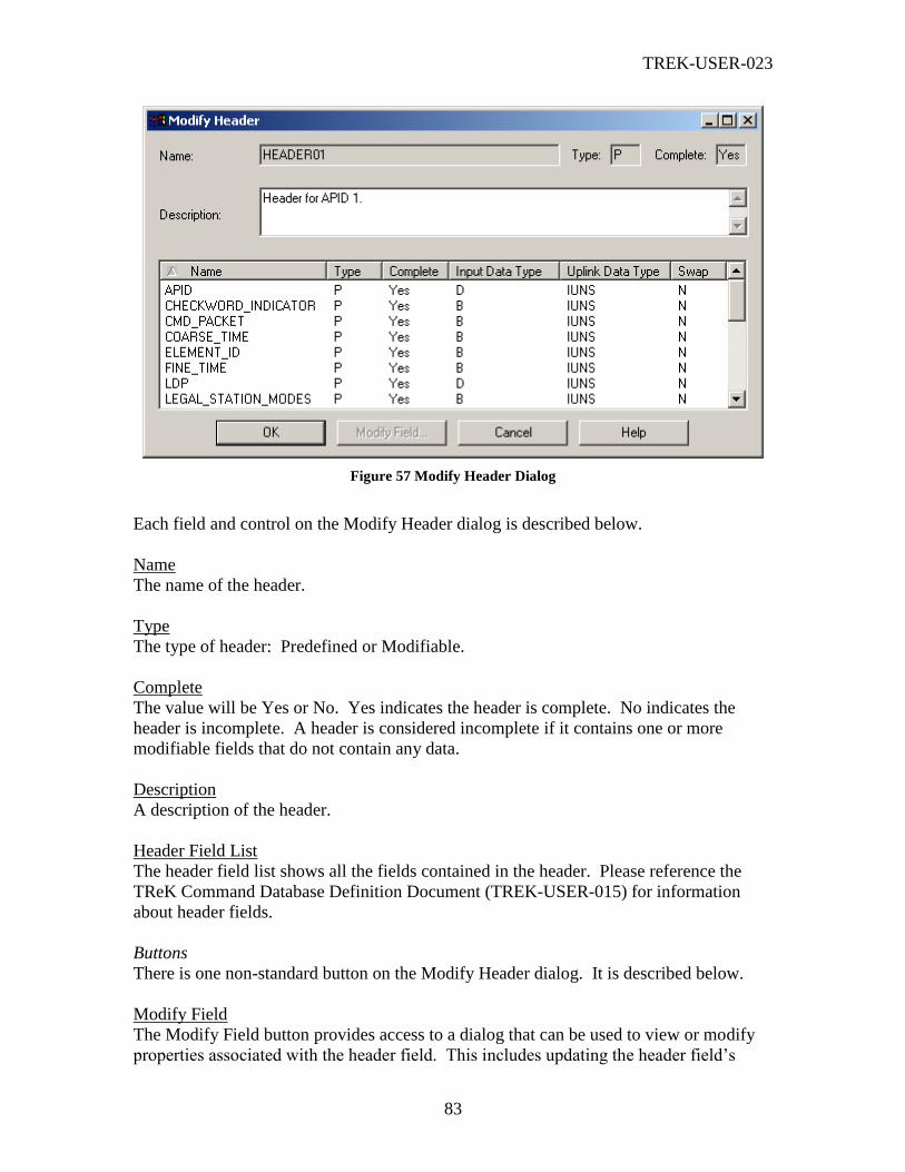
TREK-USER-023
83
Figure 57 Modify Header Dialog
Each field and control on the Modify Header dialog is described below.
Name
The name of the header.
Type
The type of header: Predefined or Modifiable.
Complete
The value will be Yes or No. Yes indicates the header is complete. No indicates the
header is incomplete. A header is considered incomplete if it contains one or more
modifiable fields that do not contain any data.
Description
A description of the header.
Header Field List
The header field list shows all the fields contained in the header. Please reference the
TReK Command Database Definition Document (TREK-USER-015) for information
about header fields.
Buttons
There is one non-standard button on the Modify Header dialog. It is described below.
Modify Field
The Modify Field button provides access to a dialog that can be used to view or modify
properties associated with the header field. This includes updating the header field’s

TREK-USER-023
84
value. The Modify button will only be available when an item in the list is selected.
Even if a field is predefined it is still possible to modify the description associated with
the field.
6.63 Modify Header Field Dialog
The Modify Header Field dialog is shown in Figure 58. This dialog is used to modify the
properties associated with a header field.
Figure 58 Modify Header Field Dialog
Each field and control on the Modify Header Field dialog is described below.
Field Name
The name of the header field. This field cannot be modified.
Complete
The value will be Yes or No. Yes indicates the header field is complete. No indicates the
header field is incomplete. A header field is considered incomplete if it does not contain
any data.

TREK-USER-023
85
Field Length
The length of the header field in bits. This field cannot be modified.
Engineering Units
The engineering unit associated with the header field. This field cannot be modified.
Byte Order
Indicates whether the header field’s byte order is no swapping, byte swapped, word
swapped, byte and word swapped, byte reversed, or word reversed. This field cannot be
modified.
Input Data Type
The header field’s input data type. This field cannot be modified.
Uplink Data Type
The header field’s uplink data type. This field cannot be modified.
Type
The type of header field. The value will be P or M. P stands for Predefined and M
stands for Modifiable. This field cannot be modified.
Description
A description of the header field.
Field Value Representation
In some cases it is possible to input the field data using different representations. The
Uplink Data Type is used to determine which representations are valid. The data that
can be entered into the Field Value will depend on the Field Value Representation
selected. For example, if binary is selected then only binary data can be entered into the
Field Value field. The Field Value field units information will reflect which type of data
should be entered.
Field Value
The Field Value field is used to update the value of the field. This information can be
entered using different number systems.
Field Values (Binary, Octal, Hexadecimal, Decimal) Group of Fields
These fields are always insensitive and are only used to display data. When you enter
information into the Field Value field, these fields will be updated to reflect the value you
entered after conversion and swapping have been applied.
6.64 Command Track Dialog
The Command Track dialog is shown in Figure 59. This dialog shows a list of all the
commands sent from your TReK system. If you push the Clear button, this will clear all
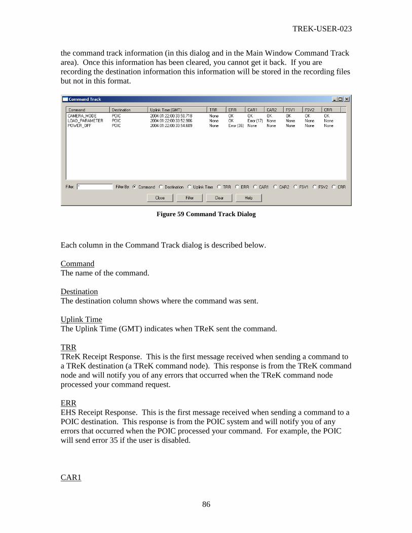
TREK-USER-023
86
the command track information (in this dialog and in the Main Window Command Track
area). Once this information has been cleared, you cannot get it back. If you are
recording the destination information this information will be stored in the recording files
but not in this format.
Figure 59 Command Track Dialog
Each column in the Command Track dialog is described below.
Command
The name of the command.
Destination
The destination column shows where the command was sent.
Uplink Time
The Uplink Time (GMT) indicates when TReK sent the command.
TRR
TReK Receipt Response. This is the first message received when sending a command to
a TReK destination (a TReK command node). This response is from the TReK command
node and will notify you of any errors that occurred when the TReK command node
processed your command request.
ERR
EHS Receipt Response. This is the first message received when sending a command to a
POIC destination. This response is from the POIC system and will notify you of any
errors that occurred when the POIC processed your command. For example, the POIC
will send error 35 if the user is disabled.
CAR1

TREK-USER-023
87
First Command Acceptance Response. Returned from the Space Station Control Center
(SSCC) via the POIC when the POIC is configured to process this message.
CAR2
Second Command Acceptance Response. Returned from the SSCC via the POIC when
the POIC is configured to process this message.
FSV1
First Flight System Verifier Response. Returned from the SSCC via the POIC when the
POIC is configured to process this message.
FSV2
Second Flight System Verifier Response. Returned from the SSCC via the POIC when
the POIC is configured to process this message.
CRR
Command Reaction Response. This response indicates if telemetry changes expected
from this command occurred. This message will only be sent if you have defined CRR
information in the POIC.
Note: Information on errors associated with command responses from the POIC can be
found in the POIC to Generic User Interface Definition Document (SSP-50305).
6.65 Command Field Calibrators Dialog
The Command Field Calibrators dialog is shown in Figure 60. This dialog shows a list of
all the unique calibrators currently in use by each destination. You can sort the list using
Calibrator Name, Calibrator Type, Description, or Destination (any of the column
headings). To sort the list based on a particular column heading, use your mouse and left
click on the column heading. When you click on a column heading you will see an up
arrow or a down arrow. The arrow indicates whether the sort is ascending or descending.
Figure 60 Command Field Calibrators Dialog
Each column in the Command Field Calibrators dialog is described below.

TREK-USER-023
88
Calibrator Name
The name of the calibrator.
Calibrator Type
The calibrator’s type. Valid types are: PC (Polynomial Coefficient), PP (Point Pair), or
SC (State Code).
Description
A description of the calibrator.
Destination
The destination the calibrator is associated with.
Dialog Buttons
There are two non-standard buttons on the Command Field Calibrators dialog. Each is
described below.
Filter
The Filter button along with the Filter field and Filter By radio buttons provide a way to
filter the list of calibrators. The Filter By radio buttons are used to indicate which
column to use for the filter. The Filter field is used to specify the filter criteria. If you
leave the Filter field blank all calibrators will be listed. If you put a * in the Filter field
all calibrators will be listed. The * character can be used to match zero or more
characters and the ? character can be used to match a single character. For example
STATE_CODE_1* means match all the calibrators that begin with the characters
STATE_CODE_1. STATE_CODE_1?1 means match all the calibrators that begin with
the characters STATE_CODE_1, followed by a single character, followed by the
character 1.
Note: When a filter has two or more * characters, only the first * character will be
interpreted as zero or more characters. The 2nd
, 3rd
, etc. instances of * will be interpreted
as a literal * character. Since most of the name fields (Calibrator, etc.) that you can filter
against do not support * as a valid character, your filter will return no items in the list if it
has more than one * character. The only exception to this is for filters against a
Description field where an * is a valid character.
You can enter more than one ? character in a filter and each of them will be interpreted as
any single character . However, all ? characters after the first * character are interpreted
as literal ? characters.
Modify
The Modify button provides access to a dialog box that can be used to view or modify
properties associated with the calibrator. The Modify button will only be available when
an item in the list is selected.

TREK-USER-023
89
6.66 Modify Polynomial Coefficient Calibrator Dialog Box
The Modify Polynomial Coefficient Calibrator dialog is shown in Figure 61. This dialog
box will appear when the Modify button is pushed for a Polynomial Coefficient
calibrator. The fields in this dialog are all read-only. The Add Set, Modify Set, and
Delete Set buttons are used to add a new set, modify an existing set, or delete an existing
set respectively. For example, to modify a particular set, the set must be selected using
the Set Number combo box and then the Modify Set button must be selected. This will
bring up a Modify Set dialog that can be used to modify the set data.
Figure 61 Modify Polynomial Coefficient Calibrator Dialog
Each field in the Modify Polynomial Coefficient Calibrator dialog is described below.
Name
The name of the calibrator.
Set Number
The set number field provides a way to select a particular set to view or modify.
TREK-USER-023
90
Description
A description of the calibrator. The Modify Description button provides access to a
dialog that can be used to modify the description.
Coefficient Information
The Coefficient Information section contains information about each of the polynomial
coefficients associated with one particular set.
Degree
The degree of the polynomial. The degree must be consistent with the data in the
coefficient fields. For example, if you enter 3 in the Degree field then the Coefficient 0,
Coefficient 1, Coefficient 2, and Coefficient 3 fields should be populated with the correct
coefficient information.
Coefficient 0 through Coefficient 9
The Coefficient fields represent each of the 10 coefficients. See the Command Database
Definition Document (TREK-USER-015) for a description of the coefficients.
Buttons
Add Set
When you push the Add Set button the Add Set dialog box described in section 6.67 will
be displayed. This dialog provides a way to add a new polynomial coefficient set for the
calibrator.
Modify Set
When you push the Modify Set button the dialog box described in section 6.68 will be
displayed. This dialog provides a way to modify an existing polynomial coefficient set
for the calibrator. It will be populated with the data corresponding to the set you selected
in the Modify Polynomial Coefficient Calibrator dialog.
Delete Set
When you push Delete Set, the currently selected set will be deleted. You will be asked
to confirm that you want to delete the set since the delete action cannot be reversed. You
cannot delete the last set.
Modify Description
When you push the Modify Description button the Modify Description dialog box will be
displayed. This dialog box is used to modify the calibrator’s description. It is described
in section 6.69.

TREK-USER-023
91
6.67 Add Set (Polynomial Coefficient Calibrator) Dialog
The Add Set dialog shown in Figure 62 is used to add a set for a polynomial coefficient
calibrator. It can be accessed by pushing the Add Set button on the Modify Polynomial
Coefficient Calibrator dialog.
Figure 62 Add Set (Polynomial Coefficient Calibrator)
6.68 Modify Set (Polynomial Coefficient Calibrator) Dialog
The Modify Set dialog shown in Figure 63 is used to modify a set for a polynomial
coefficient calibrator. It can be accessed by pushing the Modify Set button on the Modify
Polynomial Coefficient Calibrator dialog. This Modify Set dialog provides a way to
modify an existing polynomial coefficient set for a specific calibrator. It will be
populated with the data corresponding to the set you selected in the Modify Polynomial
Coefficient Calibrator dialog.
Figure 63 Modify Set (Polynomial Coefficient Calibrator)

TREK-USER-023
92
6.69 Modify Description Dialog
The Modify Description dialog is shown in Figure 64. This dialog is used to modify the
description associated with a particular processing element.
Figure 64 Modify Description Dialog
6.70 Modify Point Pair Calibrator Dialog
The Modify Point Pair Calibrator dialog is shown in Figure 65. This dialog box will
appear when the Modify button is pushed for a Point Pair Calibrator. The fields in this
dialog are all read-only. The Add Set, Modify Set, and Delete Set buttons are used to add
a new set, modify an existing set, or delete an existing set respectively. For example, to
modify a particular set, the set must be selected using the Set Number combo box and
then the Modify Set button must be selected. This will bring up a Modify Set dialog that
can be used to modify the set data.
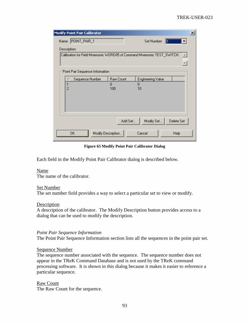
TREK-USER-023
93
Figure 65 Modify Point Pair Calibrator Dialog
Each field in the Modify Point Pair Calibrator dialog is described below.
Name
The name of the calibrator.
Set Number
The set number field provides a way to select a particular set to view or modify.
Description
A description of the calibrator. The Modify Description button provides access to a
dialog that can be used to modify the description.
Point Pair Sequence Information
The Point Pair Sequence Information section lists all the sequences in the point pair set.
Sequence Number
The sequence number associated with the sequence. The sequence number does not
appear in the TReK Command Database and is not used by the TReK command
processing software. It is shown in this dialog because it makes it easier to reference a
particular sequence.
Raw Count
The Raw Count for the sequence.

TREK-USER-023
94
Engineering Value
The Engineering Value for the sequence.
Buttons
Add Set
When you push the Add Set button the dialog described in section 6.71 will be displayed.
The Add Set dialog provides a way to add a new point pair set for the calibrator.
Modify Set
When you push the Modify Set button the dialog described in section 6.72 will be
displayed. The Modify Set dialog provides a way to modify a point pair set in the
calibrator.
Delete Set
When you push Delete Set, the currently selected set will be deleted. You will be asked
to confirm that you want to delete the set since the delete action cannot be reversed. You
cannot delete the last set.
Modify Description
When you push the Modify Description button the Modify Description dialog box will be
displayed. This dialog box is used to modify the calibrator’s description. It is described
in section 6.69.
6.71 Add Set (Point Pair Calibrator) Dialog
The Add Set dialog shown in Figure 66 is used to add a set for a point pair calibrator. It
can be accessed by pushing the Add Set button on the Modify Point Pair Calibrator
dialog box. A Point Pair Calibrator set is comprised of point pair sequences. The Add
Set dialog provides a way to add sequences, modify sequences, and delete sequences.
The Modify Sequence and Delete Sequence buttons will be insensitive unless you have a
sequence in the sequence list selected. Once a sequence has been selected these buttons
will be available.
You can sort the list of sequences by Sequence Number, Raw Count, or Engineering
Value (any of the column headings). To sort the list based on a particular column
heading, use your mouse and left click on the column heading. When you click on a
column heading you will see an up arrow or a down arrow. The arrow indicates whether
the sort is ascending or descending.

TREK-USER-023
95
Figure 66 Add Set (Point Pair Calibrator) Dialog
6.72 Modify Set (Point Pair Calibrator) Dialog
The Modify Set dialog is shown in Figure 67. It is used to modify a set associated with a
point pair calibrator. It can be accessed by pushing the Modify Set button on the Modify
Point Pair Calibrator dialog box. The Modify Set dialog will be populated with the set
that is selected in the Modify Point Pair Calibrator dialog. A Point Pair Calibrator set is
comprised of point pair sequences. The Modify Set dialog provides a way to add
sequences, modify sequences, and delete sequences. The Modify Sequence and Delete
Sequence buttons will be insensitive unless you have a sequence in the sequence list
selected. Once a sequence has been selected these buttons will be available. When you
push the Add Sequence button, the dialog described in section 6.73 is displayed. When
you push the Modify Sequence button, the dialog described in 6.74 is displayed.
You can sort the list of sequences by Sequence Number, Raw Count, or Engineering
Value (any of the column headings). To sort the list based on a particular column
heading, use your mouse and left click on the column heading. When you click on a
column heading you will see an up arrow or a down arrow. The arrow indicates whether
the sort is ascending or descending.

TREK-USER-023
96
Figure 67 Modify Set (Point Pair Calibrator) Dialog
6.73 Add Sequence (Point Pair Calibrator Set) Dialog
The Add Sequence dialog is shown in Figure 68. This dialog provides a way to add a
new sequence to a point pair set.
Figure 68 Add Sequence (Point Pair Sequence) Dialog
6.74 Modify Sequence (Point Pair Calibrator Set)
The Modify Sequence dialog shown in Figure 69 provides a way to modify a point pair
sequence associated with a point pair set.

TREK-USER-023
97
Figure 69 Modify Sequence (Point Pair Sequence) Dialog
6.75 Modify State Code Calibrator Dialog
The Modify State Code Calibrator dialog is shown in Figure 70. This dialog will appear
when the Modify button is pushed for a State Code calibrator. The fields in this dialog
are all read-only. The Add Set, Modify Set, and Delete Set buttons are used to add a new
set, modify an existing set, or delete an existing set respectively. For example, to modify
a particular set, the set must be selected using the Set Number combo box and then the
Modify Set button must be selected. This will bring up a Modify Set dialog that can be
used to modify the set data.
Figure 70 Modify State Code Calibrator Dialog
Each field in the Modify State Code Calibrator dialog is described below.
TREK-USER-023
98
Name
The name of the calibrator.
Set Number
The set number field provides a way to select a particular set to view or modify.
Description
A description of the calibrator. The Modify Description button provides access to a
dialog that can be used to modify the description.
State Code Sequence Information
The State Code Sequence Information section lists all the sequences in the state code set.
Sequence Number
The sequence number associated with the sequence. The sequence number does not
appear in the TReK Command Database and is not used by the TReK command
processing software. It is shown in this dialog because it makes it easier to reference a
particular sequence.
Raw Count
The Raw Count for the sequence.
State Code
The State Code for the sequence.
Buttons
Add Set
When you push the Add Set button the dialog described in section 6.76 will be displayed.
The Add Set dialog provides a way to add a new state code set for the calibrator.
Modify Set
When you push the Modify Set button the dialog described in section 6.77 will be
displayed. The Modify Set dialog provides a way to modify a state code set in the
calibrator.
Delete Set
When you push Delete Set, the currently selected set will be deleted. You will be asked
to confirm that you want to delete the set since the delete action cannot be reversed. You
cannot delete the last set.
Modify Description

TREK-USER-023
99
When you push the Modify Description button the Modify Description dialog box will be
displayed. This dialog box is used to modify the calibrator’s description. It is described
in section 6.69.
6.76 Add Set (State Code Calibrator)
The Add Set dialog is shown in Figure 71. This dialog is used to add a set for a state
code calibrator. It can be accessed by pushing the Add Set button on the Modify State
Code Calibrator dialog box. A State Code Calibrator set is comprised of state code
sequences. The Add Set dialog provides a way to add sequences, modify sequences, and
delete sequences. The Modify Sequence and Delete Sequence buttons will be insensitive
unless you have a sequence in the sequence list selected. Once a sequence has been
selected these buttons will be available.
You can sort the list of sequences by Sequence Number, Raw Count, or State Code (any
of the column headings). To sort the list based on a particular column heading, use your
mouse and left click on the column heading. When you click on a column heading you
will see an up arrow or a down arrow. The arrow indicates whether the sort is ascending
or descending.
Figure 71 Add Set (State Code Calibrator) Dialog
6.77 Modify Set (State Code Calibrator) Dialog
The Modify Set dialog is shown in Figure 72. This dialog is used to modify a set
associated with a state code calibrator. It can be accessed by pushing the Modify Set
button on the Modify State Code Calibrator dialog. The Modify Set dialog will be
populated with the set that is selected in the Modify State Code Calibrator dialog. A
State Code Calibrator set is comprised of state code sequences. The Modify Set dialog
provides a way to add sequences, modify sequences, and delete sequences. The Modify
Sequence and Delete Sequence buttons will be insensitive unless you have a sequence in
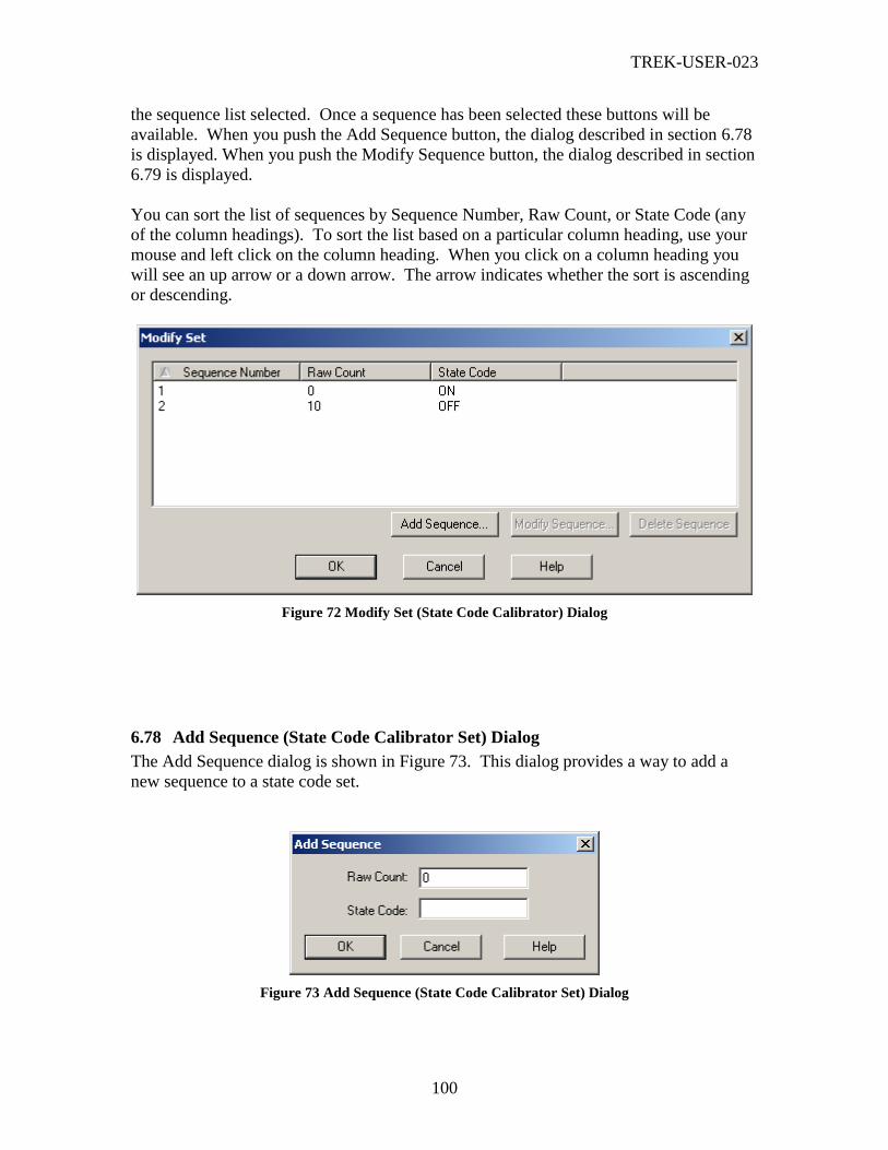
TREK-USER-023
100
the sequence list selected. Once a sequence has been selected these buttons will be
available. When you push the Add Sequence button, the dialog described in section 6.78
is displayed. When you push the Modify Sequence button, the dialog described in section
6.79 is displayed.
You can sort the list of sequences by Sequence Number, Raw Count, or State Code (any
of the column headings). To sort the list based on a particular column heading, use your
mouse and left click on the column heading. When you click on a column heading you
will see an up arrow or a down arrow. The arrow indicates whether the sort is ascending
or descending.
Figure 72 Modify Set (State Code Calibrator) Dialog
6.78 Add Sequence (State Code Calibrator Set) Dialog
The Add Sequence dialog is shown in Figure 73. This dialog provides a way to add a
new sequence to a state code set.
Figure 73 Add Sequence (State Code Calibrator Set) Dialog

TREK-USER-023
101
6.79 Modify Sequence (State Code Calibrator Set) Dialog
The Modify Sequence dialog is shown in Figure 74. This dialog provides a way to
modify a state code sequence associated with a state code set.
Figure 74 Modify Sequence (State Code Calibrator Set) Dialog
6.80 Validation Messages Dialog
The Validation Messages dialog shown in Figure 75. This dialog is displayed when an
error occurs as the result of entering invalid data into a processing element dialog such as
an Add Set dialog or a Modify Set dialog. The errors listed in this dialog will provide as
much information as possible to help you find and correct the error. You must correct all
errors before you can proceed. For a complete list of the errors that can appear in this
dialog please see on-line help.
Figure 75 Validation Messages Dialog

TREK-USER-023
102
6.81 Login Sessions Dialog
The Login Sessions dialog is shown in Figure 76. This dialog displays all the ERIS and
TReK Login sessions. These Login Sessions may or may not be in use. The dialog
shows whether the Login Session is being recorded and the status of the Login Session
(Inactive, Active, etc.).
Figure 76 Login Sessions Dialog
Buttons
There are several non-standard buttons on the Login Sessions dialog. Each is described
below.
Change Password
The Change Password button displays the Change Password dialog. This dialog provides
a way to change the password associated with your external (POIC or TReK) user
account.
Reauthenticate
The Reauthenticate button displays the Login dialog. This provides a way to
reauthenticate your ERIS Login Session. This function is not applicable for TReK Login
Sessions.
Request Reauthentication Status
The Request Reauthentication Status button provides a way to request reauthentication
status for the selected ERIS Login Session. This function is not applicable for TReK
Login Sessions.
Modify
The Modify button displays the Modify Login Session dialog. This dialog provides a
way to modify the properties associated with the Login Session such as recording or
viewing properties. The Modify Login Session dialog is identical to the Add Login
Session dialog. Please note that once a Login Session has been activated it will not be
possible to change some of the Login Session properties such as the IP Address, port, etc.
Delete
The Delete button provides a way to delete an Inactive Login Session. If a Login Session
is referenced by a destination or is Active it cannot be deleted.

TREK-USER-023
103
6.82 Set Command Processing Options Dialog
The Set Command Processing Options dialog is shown in Figure 77. This dialog
provides a way to set application defaults. For example, you can set properties associated
with command fields and how they are handled when a command is built as well as
default directories for configuration files and database files.
Figure 77 Set Command Processing Options Dialog
Each field in the Set Command Processing Options dialog is described below.
Pad Variable Length Command Fields
If this checkbox is checked when you attempt to uplink a local variable length command,
TReK will check to make sure that the command is on a word boundary and if it is not,

TREK-USER-023
104
TReK will pad the command’s variable length command field with a single byte that is
displayed in the Pad Byte field.
Note: Variable length commands can contain only one variable length field and that field
must be the last user-defined field in the command, followed only by a checksum field.
Yet Another Note: Variable length command fields will not be padded when you request to
update a POIC command. This option only applies when TReK is building the bit pattern to
pass to the POIC for uplink.
Pad Byte
This is the byte that will be used to pad variable length command fields if the “Pad
Variable Length Command Fields” checkbox is checked.
Add Terminator to String Command Fields
If this checkbox is checked, TReK will add the specified terminator to all string
command fields. If you leave the checkbox unchecked, TReK will not add a terminator.
Note: The terminator will not be added to fields with the SUND uplink data type.
Fixed Length String Command Fields Fill Byte
All fixed length string command fields will be filled with the specified fill byte.
Display Confirmation Prompt for Command Requests
This feature controls the display of a confirmation prompt for command requests issued
from the Commands dialog. If this checkbox is checked, TReK will display a command
confirmation prompt when you request one of the following command functions from the
Commands dialog: Uplink POIC Command, Uplink TReK Command, Uplink Local
Command, Update POIC Database, and Update Command Node DB. The feature is
disabled by default (unchecked).
Note: This feature is only used by the Command Processing application. If you issue a
command request through the Command User API no confirmation dialogs will be displayed
by the TReK software (regardless of this setting).
Command Processing Configuration Files Default Directory
This property provides a way to set a user-specified default directory for configuration
files. You can leave this field blank. If you leave it blank, TReK will use the following
directory:
<base_path>\configuration_files\command_processing directory.
The <base_path> on a Windows 2000 computer is shown below.

TREK-USER-023
105
<base_path> = C:\Documents and Settings\<username>\Application Data\TReK
Command Database Default Directory
This property provides a way to set a user-specified default directory for database files.
You can leave this field blank. If you leave it blank, TReK will use the following
directory:
<base_path>\command_database.
The <base_path> on a Windows 2000 computer is shown below.
<base_path> = C:\Documents and Settings\<username>\Application Data\TReK
Buttons
There is one non-standard button on the Set Command Processing Options dialog. It is
described below.
Set to Defaults
The Set to Defaults button will reset all properties in the dialog box to the original values
that were in place when the TReK software was installed.
6.83 Command Processing Statistics
The Command Processing Statistics dialog is shown in Figure 78. This dialog provides
statistics information about the command processing work currently in progress. For
example, you can use this dialog to display information about the number of segments
received, the number of packets received, the number of packets sent, etc.
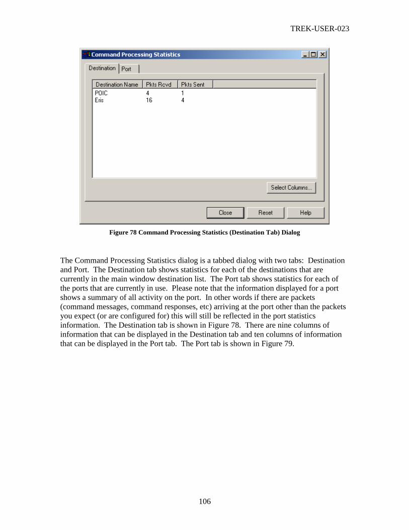
TREK-USER-023
106
Figure 78 Command Processing Statistics (Destination Tab) Dialog
The Command Processing Statistics dialog is a tabbed dialog with two tabs: Destination
and Port. The Destination tab shows statistics for each of the destinations that are
currently in the main window destination list. The Port tab shows statistics for each of
the ports that are currently in use. Please note that the information displayed for a port
shows a summary of all activity on the port. In other words if there are packets
(command messages, command responses, etc) arriving at the port other than the packets
you expect (or are configured for) this will still be reflected in the port statistics
information. The Destination tab is shown in Figure 78. There are nine columns of
information that can be displayed in the Destination tab and ten columns of information
that can be displayed in the Port tab. The Port tab is shown in Figure 79.
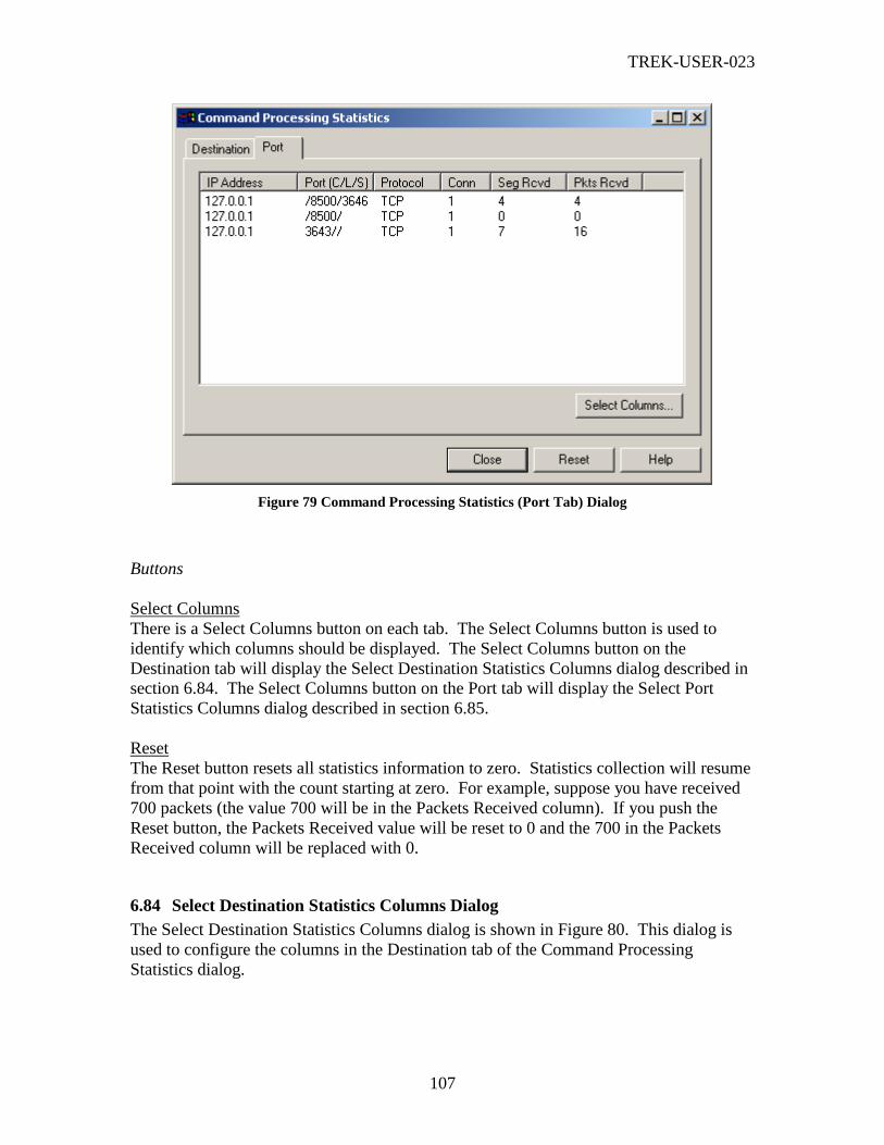
TREK-USER-023
107
Figure 79 Command Processing Statistics (Port Tab) Dialog
Buttons
Select Columns
There is a Select Columns button on each tab. The Select Columns button is used to
identify which columns should be displayed. The Select Columns button on the
Destination tab will display the Select Destination Statistics Columns dialog described in
section 6.84. The Select Columns button on the Port tab will display the Select Port
Statistics Columns dialog described in section 6.85.
Reset
The Reset button resets all statistics information to zero. Statistics collection will resume
from that point with the count starting at zero. For example, suppose you have received
700 packets (the value 700 will be in the Packets Received column). If you push the
Reset button, the Packets Received value will be reset to 0 and the 700 in the Packets
Received column will be replaced with 0.
6.84 Select Destination Statistics Columns Dialog
The Select Destination Statistics Columns dialog is shown in Figure 80. This dialog is
used to configure the columns in the Destination tab of the Command Processing
Statistics dialog.

TREK-USER-023
108
Figure 80 Select Destination Statistics Columns Dialog
Each field in the Select Destination Statistics Columns dialog is described below.
Destination Name
Destination Name. The Destination Name column cannot be hidden.
Pkts Rcvd
The number of packets received from the destination. If you check the Pkts Rcvd button,
the Pkts Rcvd column will be displayed.
Rcvd Pkts Drop
Rcvd Pkts Drop stands for Received Packets Dropped. It is the number of packets that
arrived from the destination that TReK dropped. If you check the Rcvd Pkts Drop
button, the Rcvd Pkts Drop column will be displayed.
Pkts Sent
The number of packets sent to the destination. If you check the Pkts Sent button, the Pkts
Sent column will be displayed.
Send Pkts Drop
Send Pkts Drop stands for Send Packets Dropped. It is the number of packets that TReK
attempted to send but dropped. If you check the Send Pkts Drop button, the Send Pkts
Drop column will be displayed.
Rec Pkts Drop
Rec Pkts Drop stands for Record Packets Dropped. It is the number of record packets
that TReK dropped and therefore did not successfully store in the recording file. If you
check the Rec Pkts Drop button, the Rec Pkts Drop column will be displayed.
View Pkts Drop
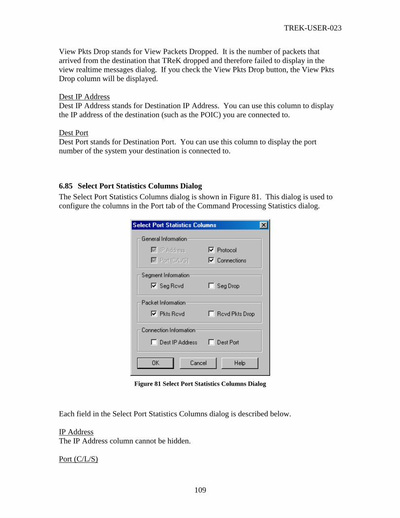
TREK-USER-023
109
View Pkts Drop stands for View Packets Dropped. It is the number of packets that
arrived from the destination that TReK dropped and therefore failed to display in the
view realtime messages dialog. If you check the View Pkts Drop button, the View Pkts
Drop column will be displayed.
Dest IP Address
Dest IP Address stands for Destination IP Address. You can use this column to display
the IP address of the destination (such as the POIC) you are connected to.
Dest Port
Dest Port stands for Destination Port. You can use this column to display the port
number of the system your destination is connected to.
6.85 Select Port Statistics Columns Dialog
The Select Port Statistics Columns dialog is shown in Figure 81. This dialog is used to
configure the columns in the Port tab of the Command Processing Statistics dialog.
Figure 81 Select Port Statistics Columns Dialog
Each field in the Select Port Statistics Columns dialog is described below.
IP Address
The IP Address column cannot be hidden.
Port (C/L/S)

TREK-USER-023
110
The Port column cannot be hidden. The port column shows a set of ports that are being
used by TReK sockets to receive and send packets. A destination may have a Client,
Listener, or Server (C/L/S) Socket/Port combination associated with it. In some cases it
is possible to have more than one socket/port associated with a destination. This occurs if
TReK is establishing a command session via TCP. For example, if TReK is configured
to listen for TCP command connection requests on a particular port (which you identified
when you added the destination) and a connection was established, the port column on
the port tab will show two entries corresponding to the destination that you added. One
of the entries will be for the Listener Socket; the other entry will be for the Server Socket
that was created by the Listener Socket when the connection was established. The
Listener’s socket/port information is identified by a port entry in the Port column that
only contains the Listeners Socket’s port number (e.g., /6100/). The Listener Socket’s
port information identifies the number of connections or Server Sockets associated with
the port. The Server Socket’s port information is identified by a port entry that contains
two values: the Listener Socket’s port number and the newly created Server Socket’s port
number (e.g., /6100/1024). The Server Socket’s port information is important because it
is the port that is actually receiving and sending the TCP packets. The third type of
socket/port combination that may be associated with a destination is a Client Socket.
Client sockets are created for UDP command sessions. For example, if TReK is
configured to command via UDP on a particular port, a Client Socket will be created for
the port. The Client Socket’s port information is identified by a port entry in the Port
column that only contains the Client Socket’s port number (e.g., 6100//).
Protocol
The Protocol – either UDP or TCP. If you check the Protocol button, the Protocol
column will be displayed.
Connections
The number of connections that have been established by the port’s socket. If you check
the Connections button, the Conn column will be displayed.
Seg Rcvd
Seg Rcvd stands for Segments Received. It is the number of TCP packet segments that
arrived from the destination. TCP may break apart or combine packets to form segments
prior to transmitting the packets to a destination. This column is only applicable for TCP.
If you check the Seg Rcvd button, the Seg Rcvd column will be displayed.
Seg Drop
Seg Drop stands for Segments Dropped. It is the number of TCP packet segments that
arrived at the destination and were dropped. TCP may break apart or combine packets to
form segments prior to transmitting the packets to a destination. This column is only
applicable for TCP. If you check the Seg Drop button, the Seg Drop column will be
displayed.
Pkts Rcvd

TREK-USER-023
111
Pkts Rcvd stands for Packets Received. It is the number of packets that arrived from the
destination. If you check the Pkts Rcvd button, the Pkts Rcvd column will be displayed.
Rcvd Pkts Drop
Rcvd Pkts Drop stands for Received Packets Dropped. It is the number of packets that
arrived at the destination and were dropped. If you check the Rcvd Pkts Drop button, the
Rcvd Pkts Drop column will be displayed.
Dest IP Address
Dest IP Address stands for Destination IP Address. You can use this column to display
the IP address of the destination (such as the POIC) that you are connected to.
Dest Port
Dest Port stands for Destination Port. You can use this column to display the port
number of the system your destination is connected to.
Note: The IP Address and Port (C/L/S) columns show the local socket you created and the
Dest IP Address and Dest Port columns show the socket you are connected to on an
external system (POIC, TReK, etc.).
6.86 Recorded Data Viewer Dialog
The Recorded Data Viewer is used to view data that is stored in a TReK recording file.
The Recorded Data Viewer can be used to view any type of TReK recording file: login
messages, commanding messages, or telemetry data. The Recorded Data Viewer works
in a Pulse mode. The Recorded Data Viewer dialog is shown in Figure 82. First you use
the Configure dialog to identify the recording files you would like to view. Then you can
start the viewing session by pushing the Start button. The Recorded Data Viewer will
display the amount of data (messages/packets) based on the Pulse Rate that you identified
in the Configure dialog. Each time you would like to view the next set of data you push
the Pulse button. You can stop at any time by pushing the Stop button. You can clear the
display by pushing the Clear button. Note the black box next to the Status field in Figure
82. This box changes color based on the activity in progress. For instance, it will be
black when the Recorded Data Viewer has not been configured. It will alternate between
green and red once the Start button has been pushed. It will turn green when data is
available, and it will turn red when all the data has been played back and there is no more
data available.

TREK-USER-023
112
Figure 82 Recorded Data Viewer Dialog
Each field in the Recorded Data Viewer dialog is described below.
Status
This Status field displays a text message to indicate the status of the Recorded Data
Viewer.
Total Pkts/Msgs Received
The Total Pkts/Msgs Received field displays the number of packets or messages that
have been retrieved from the recording files. This number will increment each time you
push the Pulse button so you know the total number of packets or messages that have
been viewed thus far.
Packet ID
This is an identifier that is associated with the recorded data. For telemetry data this is
the packet ID or APID. This is N/A for other types of data.
Packet Type
This is the packet type associated with the recorded data: ERIS, PDSS Payload, Suitcase
Simulator, EHS Command, etc.
Buttons
There are several non-standard buttons on the Recorded Data Viewer dialog. Each is
described below.
Configure
The Configure button displays the Configure dialog which provides a way to identify the
recording files you wish to view. This dialog also provides a way to configure the pulse
rate. This dialog is discussed in section 6.87.
Start/Replay
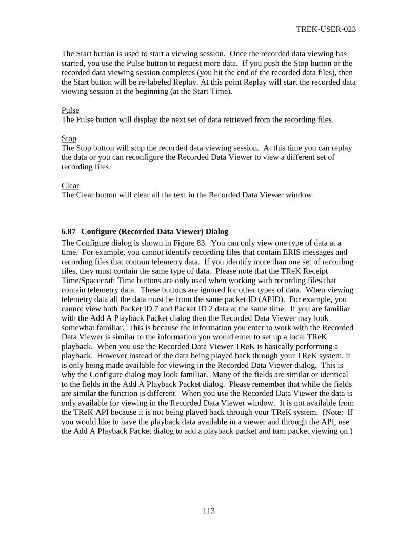
TREK-USER-023
113
The Start button is used to start a viewing session. Once the recorded data viewing has
started, you use the Pulse button to request more data. If you push the Stop button or the
recorded data viewing session completes (you hit the end of the recorded data files), then
the Start button will be re-labeled Replay. At this point Replay will start the recorded data
viewing session at the beginning (at the Start Time).
Pulse
The Pulse button will display the next set of data retrieved from the recording files.
Stop
The Stop button will stop the recorded data viewing session. At this time you can replay
the data or you can reconfigure the Recorded Data Viewer to view a different set of
recording files.
Clear
The Clear button will clear all the text in the Recorded Data Viewer window.
6.87 Configure (Recorded Data Viewer) Dialog
The Configure dialog is shown in Figure 83. You can only view one type of data at a
time. For example, you cannot identify recording files that contain ERIS messages and
recording files that contain telemetry data. If you identify more than one set of recording
files, they must contain the same type of data. Please note that the TReK Receipt
Time/Spacecraft Time buttons are only used when working with recording files that
contain telemetry data. These buttons are ignored for other types of data. When viewing
telemetry data all the data must be from the same packet ID (APID). For example, you
cannot view both Packet ID 7 and Packet ID 2 data at the same time. If you are familiar
with the Add A Playback Packet dialog then the Recorded Data Viewer may look
somewhat familiar. This is because the information you enter to work with the Recorded
Data Viewer is similar to the information you would enter to set up a local TReK
playback. When you use the Recorded Data Viewer TReK is basically performing a
playback. However instead of the data being played back through your TReK system, it
is only being made available for viewing in the Recorded Data Viewer dialog. This is
why the Configure dialog may look familiar. Many of the fields are similar or identical
to the fields in the Add A Playback Packet dialog. Please remember that while the fields
are similar the function is different. When you use the Recorded Data Viewer the data is
only available for viewing in the Recorded Data Viewer window. It is not available from
the TReK API because it is not being played back through your TReK system. (Note: If
you would like to have the playback data available in a viewer and through the API, use
the Add A Playback Packet dialog to add a playback packet and turn packet viewing on.)

TREK-USER-023
114
Figure 83 Configure (Recorded Data Viewer) Dialog
Each field in the Configure (Recorded Data Viewer) dialog is described below.
Retrieve Packets Based On (Required Field for Telemetry Data)
This option tells your TReK system whether to use TReK Receipt Time or Spacecraft
Time when telemetry packets are retrieved from the data recording files for viewing.
Spacecraft Time refers to the Embedded Time that is located in the CCSDS secondary
header for PDSS Payload packets and Suitcase Simulator packets. Spacecraft Time can
only be used when viewing telemetry data.
Playback Stream List (Required Field)
This playback stream list displays each set of recording files that you have identified. For
each set of recording files, the entry will show the Start Time, Stop Time, Packet ID, and
Packet Type associated with those recording files.
Ordering (Required Field)
Ordering identifies the ordering that TReK should use when displaying the data that has
been retrieved from the recording files. For example, you can select to display the data in
the order it was received, display the data after it has been reordered based on time, or
display the data after it has been reordered based on time and all duplicates have been
removed. Duplicates can occur if you have identified multiple sets of recorded data that
overlap in time. This can occur if you are working with recording files that contain both
realtime data and dump data. There may be some timeframe in which the same packets
were recorded in both sets of recording files. In this situation you may want to identify

TREK-USER-023
115
both sets of recording files in order to merge them together into one contiguous time
frame, but you want to remove any duplicates that were the result of the time overlap.
Note: When working with ERIS data files, command data files, or sentinel data files please
select ‘Playback In The Order Received’. Since these types of data do not contain a
sequence count or an embedded time, these packets cannot be re-ordered.
Pulse Rate (Pkts/Pulse) (Required Field)
The number of packets or messages to display each time the Pulse button is pushed.
Buttons
There are several non-standard buttons on the Configure Recorded Data Viewer dialog.
Each is described below.
Add
The Add button displays the Add dialog described in 6.88. It is used to add information
about a set of TReK recording files.
Browse
The Browse button displays the Windows Open dialog which can be used to select one or
more TReK recording files.
Modify
The Modify button is only available when an item in the list is selected. Modify provides
a way to edit an item from the list.
Delete
The Delete button is only available when an item in the list is selected. Delete provides a
way to delete an item from the list.
6.88 Add (Configure Recorded Data Viewer) Dialog
The Add dialog is shown in Figure 84. This dialog provides a way to identify one set of
recording files.
TREK-USER-023
116
Figure 84 Add (Configure Recorded Data Viewer) Dialog
Each field in the Add (Configure Recorded Data Viewer) dialog is described below.
Start Time (Required Field)
The Start Time information tells your TReK system where to start the recorded data
viewing. You can choose to start the viewing at any location within the time span
associated with the recorded data. The start time does not have to be an exact match
with the start time on any of the files. It can be any time before or after the start time on
the first file. Please remember that the Start Time is a TReK receipt time for ERIS and
command data.
Stop Time (Required Field)
The Stop Time information tells your TReK system where to stop the playback. You can
choose to stop the recorded data viewing at any location within the time span associated
with the recorded data. The stop time does not have to be an exact match with the stop
time on any of the files. It can be any time after the start time on the first file. Please
remember that the Stop Time is a TReK receipt time for ERIS and command data.
Original Base Filename (Required Field)
The Original Base Filename field is used to tell your TReK system the Base Filename
you used when you originally recorded the data. Be sure to enter exactly what you
entered when you originally recorded the data. For example, if you used the name “eris”
for the Base Filename when you recorded the data, then you should enter “eris” in the
Original Base Filename field. (Note: File extensions are not required but they are
allowed.)
Original Recorded Data Directory (Required Field)
The Original Recorded Data Directory field is used to tell your TReK system where the
original data recording files are stored. This field requires a complete directory path. An
example of this is C:\MyRecordingFiles\. If you don’t like to type or you need help
defining the complete path, you can push the … (dot dot dot) button located to the right
of the Original Recorded Data Directory field. This will bring up a Windows Browse for
Folder dialog which you can use to identify the local directory path where your recorded
data files are stored. The Browse for Folder dialog is not described in this document
since it is a typical Windows dialog box. If you need help with this dialog, please refer to
your Windows on-line help.
6.89 Manage Subnode Connections Dialog
The Manage Subnode Connections dialog is shown in Figure 85. This dialog shows all
the remote user (subnode) connections. Using this dialog you can modify the properties
associated with a subnode connection, view realtime messages for a subnode connection,
enable uplink for a subnode user, disable uplink for a subnode user, or disconnect a
subnode user.

TREK-USER-023
117
Figure 85 Manage Subnode Connections Dialog
Each column in the Manage Subnode Connections dialog is described below.
Destination Name
This is the destination that the subnode is connected to.
Destination Allows
This column indicates why the subnode was allowed to connect. The Destination can be
configured to allow anyone to connect or only specific users. This column will indicate
whether the destination allowed the subnode to connect as anyone or by using a specific
username.
Username
This column identifies the username in use by the subnode. This may be “no login” if the
user connected without logging in.
IP Address
This column shows the subnode’s IP address.
Port
This column shows the subnode’s port number.
Recording
This column indicates whether the subnode connection is being recorded.
Uplink Status
This column shows the uplink status for the subnode user. It will either be Enabled or
Disabled.
Buttons
There are several non-standard buttons on the Manage Subnode Connections dialog.
Each is described below.

TREK-USER-023
118
Modify
The Modify button will display the Modify Subnode Connection dialog. You can use
this dialog to modify properties associated with the subnode connection (such as
recording and viewing properties).
View Messages
The View Messages button will display a realtime commanding messages viewer dialog.
This dialog can be used to view all the messages going back and forth across the subnode
command connection.
Enable Uplink
The Enable Uplink button is used to Enable the Uplink Command functions for a
subnode user. This button will only be available when a subnode is selected and the
subnode’s uplink status is Disabled.
Disable Uplink
The Disable Uplink button is used to Disable the Uplink Command functions for a
subnode user. This button will only be available when a subnode is selected and the
subnode’s uplink status is Enabled.
Disconnect
The Disconnect button will drop the subnode connection and shutdown all services
associated with the subnode connection (such as viewing and recording services).
6.90 Modify Subnode Connection (General Tab) Dialog
The Modify Subnode Connection (General Tab) dialog is shown in Figure 86. This
dialog is used to modify the properties associated with a subnode connection. It contains
controls similar to those on the Add Destination User Template (General Tab) dialog.
However, while these dialogs are similar there are some important differences. There are
several properties associated with a subnode connection that cannot be modified (such as
the username). And any modifications that are made in this dialog are lost once the
connection goes away. Subnode connections are realtime entities that only exist while
the connection exists. No changes made in this dialog will ever be saved. Please
reference the Add Destination User Template (General Tab) Dialog section for
information about the controls on this tab.
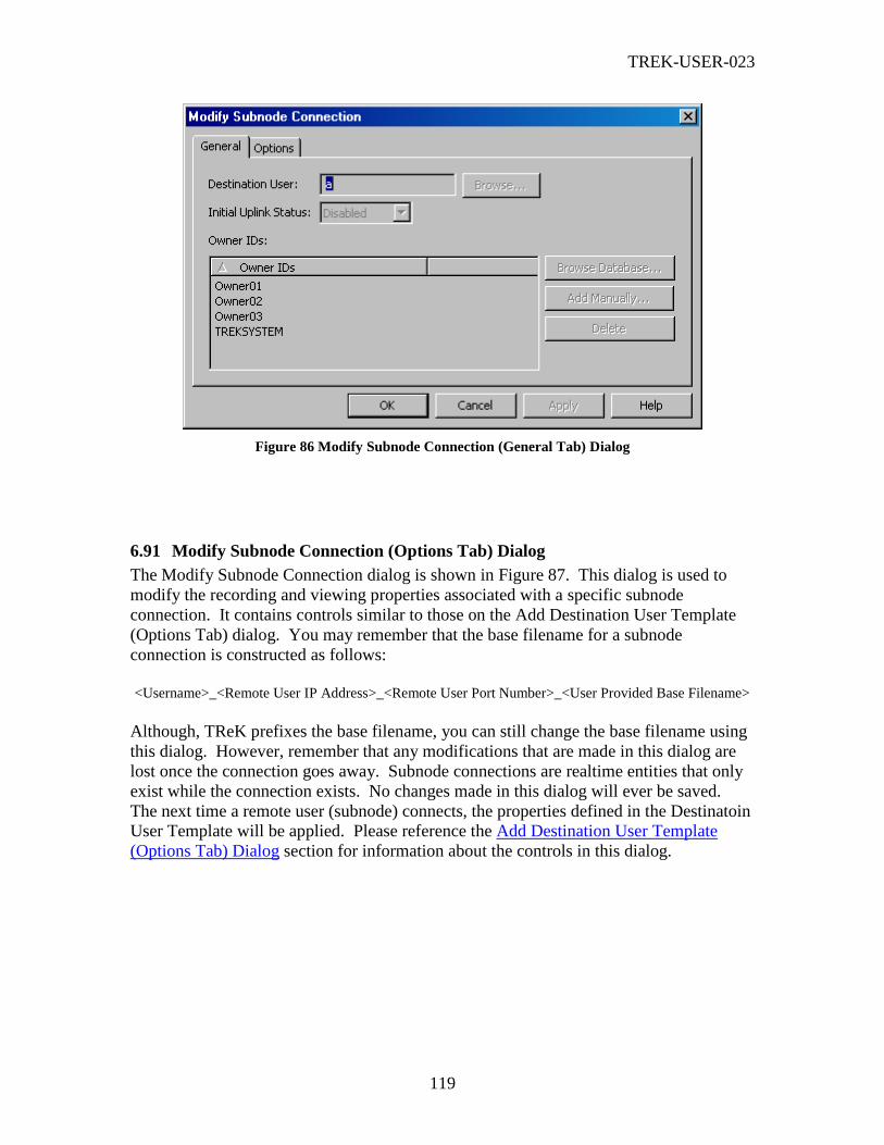
TREK-USER-023
119
Figure 86 Modify Subnode Connection (General Tab) Dialog
6.91 Modify Subnode Connection (Options Tab) Dialog
The Modify Subnode Connection dialog is shown in Figure 87. This dialog is used to
modify the recording and viewing properties associated with a specific subnode
connection. It contains controls similar to those on the Add Destination User Template
(Options Tab) dialog. You may remember that the base filename for a subnode
connection is constructed as follows:
<Username>_<Remote User IP Address>_<Remote User Port Number>_<User Provided Base Filename>
Although, TReK prefixes the base filename, you can still change the base filename using
this dialog. However, remember that any modifications that are made in this dialog are
lost once the connection goes away. Subnode connections are realtime entities that only
exist while the connection exists. No changes made in this dialog will ever be saved.
The next time a remote user (subnode) connects, the properties defined in the Destinatoin
User Template will be applied. Please reference the Add Destination User Template
(Options Tab) Dialog section for information about the controls in this dialog.

TREK-USER-023
120
Figure 87 Modify Subnode Connection (Options Tab) Dialog
6.92 Delete Destination Warning Message Dialog
The Delete Destination Warning message dialog will appear if you attempt to delete a
destination from the destination list in the main window. If you are sure you want to
proceed answer Yes. If you do not want to proceed answer No and no action will be
taken.
Figure 88 Delete Destination Warning Message Dialog
6.93 Invalid Configuration Information Dialog
The Invalid Configuration Information dialog is shown in Figure 89. This dialog only
appears if you attempt to open a configuration file that contains invalid configuration
information. This usually happens when you move a configuration file from one machine
to another. For example, when you save a configuration file, the destinations and all the
information associated with the destinations (including the IP address information and the
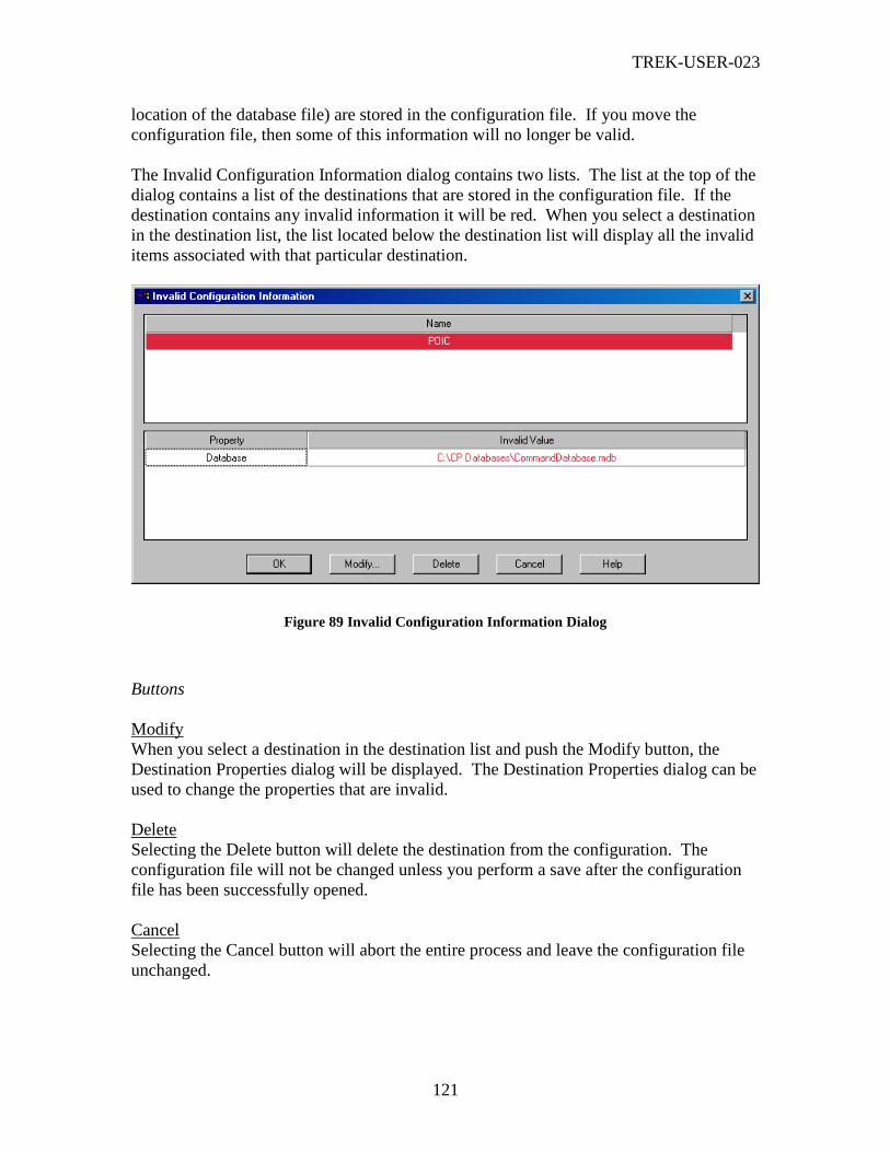
TREK-USER-023
121
location of the database file) are stored in the configuration file. If you move the
configuration file, then some of this information will no longer be valid.
The Invalid Configuration Information dialog contains two lists. The list at the top of the
dialog contains a list of the destinations that are stored in the configuration file. If the
destination contains any invalid information it will be red. When you select a destination
in the destination list, the list located below the destination list will display all the invalid
items associated with that particular destination.
Figure 89 Invalid Configuration Information Dialog
Buttons
Modify
When you select a destination in the destination list and push the Modify button, the
Destination Properties dialog will be displayed. The Destination Properties dialog can be
used to change the properties that are invalid.
Delete
Selecting the Delete button will delete the destination from the configuration. The
configuration file will not be changed unless you perform a save after the configuration
file has been successfully opened.
Cancel
Selecting the Cancel button will abort the entire process and leave the configuration file
unchanged.

TREK-USER-023
122
6.94 Close Configuration Warning Message Dialog
The Close Configuration Warning message dialog will appear if you attempt to perform a
New or Open and there are packets in the packet list. If you are sure you want to proceed
answer Yes. If you do not want to proceed answer No and no action will be taken.
Figure 90 Close Configuration Warning Message Dialog
6.95 Save Changes Message Dialog
If you select New, Open, or Exit, and the current configuration has not been saved, the
Save Changes message dialog will be displayed. If you are exiting the application, the
application will Exit after you respond to the Save Changes dialog.
Figure 91 Save Changes Message Dialog
6.96 Exit Confirmation Message Dialog
The Exit Confirmation message dialog is displayed to help you avoid exiting the
Command Processing application by accident. It will only be displayed if you exit the
application with the current configuration unchanged. If the configuration has changed
you will be prompted with the Save Changes dialog instead of the Exit Confirmation
dialog. If you are prompted with the Exit Confirmation dialog and you are sure you want
to exit answer Yes. If you do not want to exit the application answer No and the
application will not proceed with the exit.

TREK-USER-023
123
Figure 92 Exit Confirmation Message
7 Special Topics
This section addresses a few of the special topics associated with the Command
Processing application. The information in this section can be useful in understanding
why you have to enter some of the information required in some of the dialogs.
There are no special topics at this time.
8 Messages
Validation messages and error messages are listed in the Command Processing On-Line
Help.
TREK-USER-023
124
Appendix A Glossary Note: This Glossary is global to all TReK documentation. All entries listed may not be
referenced within this document.
Application Programming Interface
(API)
A set of functions used by an application program
to provide access to a system’s capabilities.
Application Process Identifier
(APID)
An 11-bit field in the CCSDS primary packet
header that identifies the source-destination pair
for ISS packets. The type bit in the primary header
tells you whether the APID is a payload or system
source-destination.
Calibration The transformation of a parameter to a desired
physical unit or text state code.
Communications Outage Recorder System that captures and stores payload science,
health and status, and ancillary data during TDRSS
zone of exclusion.
Consultative Committee for Space
Data Systems (CCSDS) format
Data formatted in accordance with
recommendations or standards of the CCSDS.
Consultative Committee for Space
Data Systems (CCSDS) packet
A source packet comprised of a 6-octet CCSDS
defined primary header followed by an optional
secondary header and source data, which together
may not exceed 65535 octets.
Conversion Transformation of downlinked spacecraft data
types to ground system platform data types.
Custom Data Packet A packet containing a subset of parameters that
can be selected by the user at the time of request.
Cyclic Display Update Mode A continuous update of parameters for a particular
display.
Decommutation (Decom) Extraction of a parameter from telemetry.
Discrete Values Telemetry values that have states (e.g., on or off).

TREK-USER-023
125
Dump During periods when communications with the
spacecraft are unavailable, data is recorded
onboard and played back during the next period
when communications resume. This data, as it is
being recorded onboard, is encoded with an
onboard embedded time and is referred to as dump
data.
Enhanced HOSC System (EHS) Upgraded support capabilities of the HOSC
systems to provide multi-functional support for
multiple projects. It incorporates all systems
required to perform data acquisition and
distribution, telemetry processing, command
services, database services, mission support
services, and system monitor and control services.
Exception Monitoring A background process capable of continuously
monitoring selected parameters for Limit or
Expected State violations. Violation notification is
provided through a text message.
Expected State Sensing Process of detecting a text state code generator in
an off-nominal state.
EXPRESS An EXPRESS Rack is a standardized payload rack
system that transports, stores and supports
experiments aboard the International Space
Station. EXPRESS stands for EXpedite the
PRocessing of Experiments to the Space Station.
File transfer protocol (ftp) Protocol to deliver file-structured information from
one host to another.
Flight ancillary data A set of selected core system data and payload
health and status data collected by the USOS
Payload MDM, used by experimenters to interpret
payload experiment results.
TREK-USER-023
126
Grayed out Refers to a menu item that has been made
insensitive, which is visually shown by making the
menu text gray rather than black. Items that are
grayed out are not currently available.
Greenwich Mean Time (GMT) The solar time for the meridian passing through
Greenwich, England. It is used as a basis for
calculating time throughout most of the world.
Ground ancillary data A set of selected core system data and payload
health and status data collected by the POIC,
which is used by experimenters to interpret
payload experiment results. Ground Ancillary
Data can also contain computed parameters
(pseudos).
Ground receipt time Time of packet origination. The time from the
IRIG-B time signal received.
Ground Support Equipment (GSE) GSE refers to equipment that is brought in by the
user (i.e. equipment that is not provided by the
POIC).
Ground Support Equipment Packet A CCSDS Packet that contains data extracted from
any of the data processed by the Supporting
Facility and the format of the packet is defined in
the Supporting Facility’s telemetry database.
Huntsville Operations Support
Center (HOSC)
A facility located at the Marshall Space Flight
Center (MSFC) that provides scientists and
engineers the tools necessary for monitoring,
commanding, and controlling various elements of
space vehicle, payload, and science experiments.
Support consists of real-time operations planning
and analysis, inter- and intra-center ground
operations coordination, facility and data system
resource planning and scheduling, data systems
monitor and control operations, and data flow
coordination.
TREK-USER-023
127
IMAQ ASCII A packet type that was added to TReK to support a
very specific application related to NASA’s Return
to Flight activities. It is not applicable to ISS. It is
used to interface with an infrared camera that
communicates via ASCII data.
Limit Sensing Process of detecting caution and warning
conditions for a parameter with a numerical value.
Line Outage Recorder Playback A capability provided by White Sands Complex
(WSC) to play back tapes generated at WSC
during ground system communication outages.
Measurement Stimulus Identifier
(MSID)
Equivalent to a parameter.
Monitoring A parameter value is checked for sensing
violations. A message is generated if the value is
out of limits or out of an expected state.
Parameter TReK uses the generic term parameter to mean any
piece of data within a packet. Sometimes called a
measurement or MSID in POIC terminology.
Payload Data Library (PDL) An application that provides the interface for the
user to specify which capabilities and requirements
are needed to command and control his payload.
Payload Data Services Systems
(PDSS)
The data distribution system for ISS. Able to route
data based upon user to any of a number of
destinations.
Payload Health and Status Data Information originating at a payload that reveals
the payload’s operational condition, resource
usage, and its safety/anomaly conditions that could
result in damage to the payload, its environment or
the crew.
Payload Operations Integration
Center (POIC)
Manages the execution of on-orbit ISS payloads
and payload support systems in
coordination/unison with distributed International
Partner Payload Control Centers, Telescience
Support Centers (TSC’s) and payload-unique
remote facilities.

TREK-USER-023
128
Payload Rack Checkout Unit
(PRCU)
The Payload Rack Checkout Unit is used to verify
payload to International Space Station interfaces
for U.S. Payloads.
Playback Data retrieved from some recording medium and
transmitted to one or more users.
Pseudo Telemetry (pseudo data) Values that are created from calculations instead of
directly transported telemetry data. This pseudo
data can be created from computations or scripts
and can be displayed on the local PC.
Remotely Generated Command A command sent by a remote user whose content
is in a raw bit pattern format. The commands
differ from predefined or modifiable commands in
that the content is not stored in the POIC Project
Command Database (PCDB).
Science data Sensor or computational data generated by
payloads for the purpose of conducting scientific
experiments.
Subset A collection of parameters from the total
parameter set that is bounded as an integer number
of octets but does not constitute the packet itself.
A mini-packet.
Super sampled A parameter is super sampled if it occurs more
than once in a packet.
Swap Type A flag in the Parameter Table of the TReK
database that indicates if the specified datatype is
byte swapped (B), word swapped (W), byte and
word swapped (X), byte reversal (R), word
reversal (V) or has no swapping (N).
Switching A parameter’s value can be used to switch between
different calibration and sensing sets. There are
two types of switching on TReK: range and state
code.

TREK-USER-023
129
Transmission Control Protocol
(TCP)
TCP is a connection-oriented protocol that
guarantees delivery of data.
Transmission Control Protocol
(TCP) Client
A TCP Client initiates the TCP connection to
connect to the other party.
Transmission Control Protocol
(TCP) Server
A TCP Server waits for (and accepts connections
from) the other party.
Telemetry Transmission of data collected form a source in
space to a ground support facility. Telemetry is
downlink only.
Telescience Support Center (TSC) A TSC is a NASA funded facility that provides the
capability to plan and operate on-orbit facility
class payloads and experiments, other payloads
and experiments, and instruments.
User Application Any end-user developed software program that
uses the TReK Application Programming Interface
software. Used synonymously with User Product.
User Data Summary Message
(UDSM)
Packet type sent by PDSS that contains
information on the number of packets sent during a
given time frame for a PDSS Payload packet. For
details on UDSM packets, see the POIC to Generic
User IDD (SSP-50305).
Uplink format The bit pattern of the command or file uplinked.
User Datagram Protocol (UDP) UDP is a connection-less oriented protocol that
does not guarantee delivery of data. In the TCP/IP
protocol suite, the UDP provides the primary
mechanism that application programs use to send
datagrams to other application programs. In
addition to the data sent, each UDP message
contains both a destination port number and a fully
qualified source and destination addresses making
it possible for the UDP software on the destination
to deliver the message to the correct recipient
process and for the recipient process to send a
reply.

TREK-USER-023
130
User Product Any end-user developed software program that
uses the TReK Application Programming Interface
software. Used synonymously with User
Application.
Web Term used to indicate access via HTTP protocol;
also referred to as the World Wide Web (WWW).

TREK-USER-023
131
Appendix B Acronyms Note: This acronym list is global to all TReK documentation. Some acronyms listed
may not be referenced within this document.
AOS Acquisition of Signal
API Application Programming Interface
APID Application Process Identifier
ASCII American Standard Code for Information Interchange
CAR Command Acceptance Response
CAR1 First Command Acceptance Response
CAR2 Second Command Acceptance Response
CCSDS Consultative Committee for Space Data Systems
CDB Command Database
CDP Custom Data Packet
COR Communication Outage Recorder
COTS Commercial-off-the-shelf
CRR Command Reaction Response
DSM Data Storage Manager
EHS Enhanced Huntsville Operations Support Center (HOSC)
ERIS EHS Remote Interface System
ERR EHS Receipt Response
EXPRESS Expediting the Process of Experiments to the Space Station
ES Expected State
FAQ Frequently Asked Question
FDP Functionally Distributed Processor
FSV Flight System Verifier
FSV1 First Flight System Verifier
FSV2 Second Flight System Verifier
FPD Flight Projects Directorate
FTP File Transfer Protocol
GMT Greenwich Mean Time
GRT Ground Receipt Time
GSE Ground Support Equipment
HOSC Huntsville Operations Support Center
ICD Interface Control Document
IMAQ ASCII Image Acquisition ASCII
IP Internet Protocol
ISS International Space Station
LDP Logical Data Path
LES Limit/Expected State
LOR Line Outage Recorder
LOS Loss of Signal
MCC-H Mission Control Center – Houston
MOP Mission, Operational Support Mode, and Project
MSFC Marshall Space Flight Center
MSID Measurement Stimulus Identifier

TREK-USER-023
132
NASA National Aeronautics and Space Administration
OCDB Operational Command Database
OS Operating System
PC Personal Computer, also Polynomial Coefficient
PCDB POIC Project Command Database
PDL Payload Data Library
PDSS Payload Data Services System
PGUIDD POIC to Generic User Interface Definition Document
POIC Payload Operations Integration Center
PP Point Pair
PRCU Payload Rack Checkout Unit
PSIV Payload Software Integration and Verification
RPSM Retrieval Processing Summary Message
SC State Code
SCS Suitcase Simulator
SSP Space Station Program
SSCC Space Station Control Center
SSPF Space Station Processing Facility
TCP Transmission Control Protocol
TReK Telescience Resource Kit
TRR TReK Receipt Response
TSC Telescience Support Center
UDP User Datagram Protocol
UDSM User Data Summary Message
URL Uniform Resource Locator
USOS United States On-Orbit Segment
VCDU Virtual Channel Data Unit
VCR Video Cassette Recorder
VPN Virtual Private Network

TREK-USER-023
133
Appendix C Managing Destination Security Destination security is based on the security configuration set in the Remote Services
application and the configuration of the properties set on the destination dialog’s Manage
tab. The information below shows the results of combining different security
configuration properties. Each picture below consists of three areas.
Left Area
The left area shows two TReK subnode computers that will be connecting to a TReK
command node computer. The Command Processing application on each subnode
computer contains one TReK destination. The subnode computer boxes also show the
username that will be used when the subnode logs into the command node.
Middle Area
The middle column shows the TReK command node computer. The TReK command
node computer box shows two pieces of information: (1) The security configuration set
in the Remote Services application and (2) Destination user information for the single
destination in the Command Processing application.
Right Area
The column on the right explains how the security rules will be applied when the subnode
computers attempt to login to the command node computer and request to use the
destination on the command node.
Subnode Command Node
Destination:
Specify
UserA
UserB
UserA
Subnode
UserB
Results
Subnode UserA will not be allowed to connect
to the destination. Since the security
configuration does not require a login, UserA
connects without a username. Since there is
no username, the username does not match
UserA or UserB. Therefore, subnode UserA
will not be allowed to connect to the
destination.
Subnode UserB will not be allowed to connect
to the destination for the same reason that
UserA cannot connect to the destination
(because UserB has logged in with no
username).
Security: Allow All Connections
Security: Check Source IP Address
Subnode Command Node
Destination:
Specify
UserA
UserB
UserA
Subnode
UserB
Results
Subnode UserA will not be allowed to connect
to the destination. Since the security
configuration does not require a login, UserA
connects without a username. Since there is
no username, the username does not match
UserA or UserB. Therefore, subnode UserA
will not be allowed to connect to the
destination.
Subnode UserB will not be allowed to connect
to the destination for the same reason that
UserA cannot connect to the destination
(because UserB has logged in with no
username).
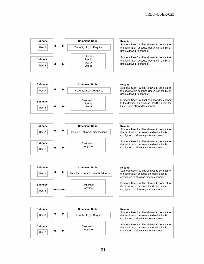
TREK-USER-023
134
Security: Login Required
Subnode Command Node
Destination:
Specify
UserA
UserB
UserA
Subnode
UserB
Results
Subnode UserA will be allowed to connect to
the destination because UserA is in the list of
users allowed to connect.
Subnode UserB will be allowed to connect to
the destination because UserB is in the list of
users allowed to connect.
Security: Login Required
Subnode Command Node
Destination:
Specify
UserA
UserA
Subnode
UserB
Results
Subnode UserA will be allowed to connect to
the destination because UserA is in the list of
users allowed to connect.
Subnode UserB will not be allowed to connect
to the destination because UserB is not in the
list of users allowed to connect.
Security: Allow All Connections
Subnode Command Node
Destination:
Anyone
UserA
Subnode
UserB
Results
Subnode UserA will be allowed to connect to
the destination because the destination is
configured to allow anyone to connect.
Subnode UserB will be allowed to connect to
the destination because the destination is
configured to allow anyone to connect.
Security: Check Source IP Address
Subnode Command Node
Destination:
Anyone
UserA
Subnode
UserB
Results
Subnode UserA will be allowed to connect to
the destination because the destination is
configured to allow anyone to connect.
Subnode UserB will be allowed to connect to
the destination because the destination is
configured to allow anyone to connect.
Security: Login Required

TREK-USER-023
135
Appendix D Using Owner IDs to Map Commands to Destination Users Mapping commands from the Command Node to Subnodes is an important part of
managing a destination. This appendix describes how this mapping takes place.
If you’re familiar with TReK commanding then you know that there is a specific set of
commands assigned to each destination in Command Processing. But where does this list
of commands come from? Well, it depends on the type of destination. If it’s a POIC
destination, the command list is sent to TReK from the POIC. If it’s a Suitcase Simulator
or PRCU destination, the command list is created by the user when the destination is
created. This is done by using the Commands Tab on the Add Suitcase Simulator (or
PRCU) Destination dialog. If it’s a TReK destination, the command list is sent by the
command node (that the TReK destination is connected to) to the subnode.
Let’s step back a moment and look at how things work with a POIC destination. When
you activate a POIC destination, you log into the POIC (ERIS) and the POIC sends back
a list of commands. The POIC knows which commands to allow for a user based on the
User Account (login) and information in the POIC Command database. Figure 93 shows
that each command in the POIC command database has an Owner ID.
Command 1
Command 2
Command 5
Command 3
Owner ID 1
Owner ID 1
POIC Command Database
Owner ID 2
Owner ID 3
Figure 93 Command Database Command/Owner ID Mapping
To allow a user access to a command, the POIC must allow the User Account access to
the Owner ID. Figure 94 shows that each POIC User Account has one or more Owner
IDs mapped to it. The commands associated with those Owner IDs are then
automatically mapped to that POIC User Account. Therefore, when you log into the
POIC, the list of commands that are returned to you are based on the user account that
you log into, and the Owner IDs (and their associated commands) that are mapped to that
user account.

TREK-USER-023
136
POIC User Account
Owner ID 1
Owner ID 2
Owner ID 3
Command 1
Command 2
Command 5
Command 3
Figure 94 User Account, Owner IDs, and Commands
Now that we have looked at how this process works with a POIC Destination, let’s look
at how things work for a TReK Destination.
When you activate a TReK Destination on a subnode, you log into the TReK Command
Node. During the login process you are prompted to select a destination to connect to.
Both the login and the destination you select play a role in determining what command
list is sent back to you.
Let’s take a look at what happens on the Command Node. Take a look at Figure 95 and
Figure 96. Figure 95 shows the Manage tab. Figure 96 shows a picture of the Add
Destination User Template dialog. This is the dialog that is displayed when you push the
Add button to add a Destination User Template.

TREK-USER-023
137
Figure 95 Add POIC Destination (Manage Tab) Dialog
Figure 96 Add Destination User Template Dialog

TREK-USER-023
138
When you add a Destination User Template, you will define a TReK user account and a
list of Owner IDs. The TReK Command Database is similar to the POIC Command
Database in that each command has a single Owner ID. So when you assign a list of
Owner IDs to a Destination User, this will automatically assign the list of commands
associated with those Owner IDs to this destination user template.
Here are a few other things to note:
When mapping commands from a command node destination to a subnode, the
subnode will only have access to the commands (or a subset of the commands) that
are associated with the destination. So if a command is not associated with the
destination it cannot be mapped to a subnode. What happens if you specify an Owner
ID that has one or more commands that are not associated with the destination? If
that happens, the command(s) will not show up in the subnode’s command list.
What happens if the subnode does not provide a user login (because the security
configuration does not require a login)? If that is the case, then the subnode will only
be allowed to use the destination if the destination is configured to allow “Anyone” to
use the destination. In this case, the command list sent to the subnode will be based
on how the “Anyone” destination user template is configured (the Owner IDs list
associated with the Anyone destination user template).