Embed Size (px)
Citation preview

Marine Safety Investigation Unit
MARINE SAFETY INVESTIGATION REPORT
Safety investigation into the cargo deck crane failure on board the
Maltese registered bulk carrier
TRAPEZITZA
in the port of Damietta, Egypt
on 22 January 2017
201701/020
MARINE SAFETY INVESTIGATION REPORT NO. 02/2018
FINAL

ii
Investigations into marine casualties are conducted under the provisions of the Merchant
Shipping (Accident and Incident Safety Investigation) Regulations, 2011 and therefore in
accordance with Regulation XI-I/6 of the International Convention for the Safety of Life at
Sea (SOLAS), and Directive 2009/18/EC of the European Parliament and of the Council of 23
April 2009, establishing the fundamental principles governing the investigation of accidents
in the maritime transport sector and amending Council Directive 1999/35/EC and Directive
2002/59/EC of the European Parliament and of the Council.
This safety investigation report is not written, in terms of content and style, with litigation in
mind and pursuant to Regulation 13(7) of the Merchant Shipping (Accident and Incident
Safety Investigation) Regulations, 2011, shall be inadmissible in any judicial proceedings
whose purpose or one of whose purposes is to attribute or apportion liability or blame, unless,
under prescribed conditions, a Court determines otherwise.
The objective of this safety investigation report is precautionary and seeks to avoid a repeat
occurrence through an understanding of the events of 22 January 2017. Its sole purpose is
confined to the promulgation of safety lessons and therefore may be misleading if used for
other purposes.
The findings of the safety investigation are not binding on any party and the conclusions
reached and recommendations made shall in no case create a presumption of liability
(criminal and/or civil) or blame. It should be therefore noted that the content of this safety
investigation report does not constitute legal advice in any way and should not be construed
as such.
© Copyright TM, 2018.
This document/publication (excluding the logos) may be re-used free of charge in any format
or medium for education purposes. It may be only re-used accurately and not in a misleading
context. The material must be acknowledged as TM copyright.
The document/publication shall be cited and properly referenced. Where the MSIU would
have identified any third party copyright, permission must be obtained from the copyright
holders concerned.
MARINE SAFETY INVESTIGATION UNIT
Malta Transport Centre
Marsa MRS 1917
Malta

iii
CONTENTS
LIST OF REFERENCES AND SOURCES OF INFORMATION .......................................... iv
GLOSSARY OF TERMS AND ABBREVIATIONS ................................................................v
SUMMARY ............................................................................................................................. vi
1 FACTUAL INFORMATION .............................................................................................1 1.1 Vessel, Voyage and Marine Casualty Particulars .......................................................1 1.2 Description of Vessel .................................................................................................2
1.2.1 MV Trapezitza ........................................................................................................2 1.3 Crew ...........................................................................................................................2 1.4 Environment ...............................................................................................................2 1.5 Maintenance and Testing ............................................................................................3
1.5.1 The slewing ring bearing ........................................................................................3 1.5.2 Maintenance schedule and regime ..........................................................................4 1.5.3 Testing procedures ..................................................................................................5
1.5.3.1 Grease test ......................................................................................................5 1.5.3.2 Rocking test ....................................................................................................6
1.6 Narrative .....................................................................................................................9 1.7 Damage to the Vessel and Fittings ...........................................................................11 1.8 Similar Accidents on Board ......................................................................................11
2 ANALYSIS .......................................................................................................................12 2.1 Purpose .....................................................................................................................12 2.2 Cause of the Accident ...............................................................................................12 2.3 Cause of the Slewing Ring Bearing Failure .............................................................13 2.4 Slewing Bearing Design and Testing .......................................................................17
2.4.1 Interpretation of the rocking test results ...............................................................17 2.4.2 Measurement taking during rocking test ..............................................................19 2.4.3 Grease test ............................................................................................................20 2.4.4 Metallurgical quality of bearing steel ...................................................................20
2.5 Missing Cues ............................................................................................................20
3 CONCLUSIONS ...............................................................................................................24 3.1 Immediate Safety Factor ...........................................................................................24 3.2 Latent Conditions and other Safety Factors .............................................................24
4 SAFETY ACTIONS .........................................................................................................25

iv
LIST OF REFERENCES AND SOURCES OF INFORMATION
Crew members and managers MV Trapezitza
DNV-GL Survey Statements
High Technology Park, Technical University, Varna
MacGregor Inspection and Service Information Manual

v
GLOSSARY OF TERMS AND ABBREVIATIONS
CMS Continuous machinery service
Fe Iron
Gt Grosse tonnage
kW Kilowatts
LT Local time
m metres
mm millimetres
MSIU Marine Safety Investigation Unit
mt Metric tonnes
MV Motor vessel
Na Sodium
nm Nautical miles
No. Number
PMS Planned maintenance system
ppm Parts per million
PQ Particle quantifier
rpm Revolutions per minute
Si Silicone
SMS Safety management system

vi
SUMMARY
On 22 January 2017, at about 0010, cargo deck crane no. 1, fitted on board the
Maltese registered bulk carrier Trapezitza, experienced a catastrophic failure during
cargo operations in the port of Damietta, Egypt.
Consequently, the cargo deck crane’s combined unit and jib parted from the pedestal
base and fell on the jetty, coming in contact with the cargo hold hatch cover and main
deck railings.
Discharging operations were suspended and the managers arranged for the cargo to be
discharged by shore cranes. The remaining cranes on board were also thoroughly
inspected.
The safety investigation concluded that the immediate cause of the accident was the
failure of the slewing ring bearing, as a result of excessive wear and tear in the outer
ring. This led to spalling of the ball bearings and raceways, which was augmented by
metal particle contaminated grease.
Taking into consideration the safety actions taken by the Company, no safety
recommendations have been issued by the Marine Safety Investigation Unit.

1
1 FACTUAL INFORMATION
1.1 Vessel, Voyage and Marine Casualty Particulars
Name TREPEZITZA
Flag Malta
Classification Society DNV GL
IMO Number 9145231
Type Bulk Carrier
Registered Owner TRAPEZITZA Maritime Ltd.
Managers Navigation Maritime Bulgare
Construction Steel
Length overall 168.58 m
Registered Length 159.72 m
Gross Tonnage 13965
Minimum Safe Manning 13
Authorised Cargo Solid Bulk
Port of Departure Berdyansk, Ukraine
Port of Arrival Damietta, Egypt
Type of Voyage International
Cargo Information Sea salt (1,836 mt)
Manning 19
Date and Time 22 January 2017 at 00:10
Type of Marine Casualty Less Serious Marine Casualty
Place on Board Freeboard deck
Injuries/Fatalities None
Damage/Environmental Impact None
Ship Operation Alongside Moored / Loading
Voyage Segment Arrival
External & Internal Environment Night-time, visibility 8 nm. Northerly light air
and air and sea temperatures of 16 °C
Persons on Board 19

2
1.2 Description of Vessel
1.2.1 MV Trapezitza
Trapezitza is a 13,695 gt, handy size bulk carrier owned by Trapezitza Maritime Ltd.
and managed by Navigation Maritime Bulgare, Bulgaria. The vessel was built by
Bulyard Shipbuilding Industry, Varna Yard, Bulgaria in 2004, and is classed with
DNV-GL.
The vessel has a length overall of 168.58 m, a moulded breadth of 25.0 m and a
moulded depth of 11.5 m. The vessel has a summer draught of 8.52 m, corresponding
to a summer deadweight of 21,454 tonnes. Trapezitza has five cargo holds and is
equipped with three cargo deck cranes.
Propulsive power is provided by an 8-cylinder BMZ-B&W 8L42MC, single acting,
two stroke, slow speed diesel engine, producing 5,884 kW at 154 rpm. This drives a
fixed pitch propeller to give a service speed of about 14.0 knots.
1.3 Crew
The Minimum Safe Manning Certificate issued by the flag State Administration
stipulated a crew of 13 persons, including six officers. At the time of the accident, the
vessel was manned in excess of the minimum safe manning requirements.
All crew members were Bulgarian nationals and the working language was Bulgarian.
1.4 Environment
According to the deck log book entries, there was a Northerly light wind. Weather
was clear and visibility was good. The outside air and sea temperatures were 16 ºC.

3
1.5 Maintenance and Testing
1.5.1 The slewing ring bearing
The slewing ring bearing is a key component on cargo deck cranes. The main
function of the slewing ring bearing is to provide a rotational attachment point to
secure the rotating cargo deck crane to the fixed pedestal mount. There are various
types of slewing ring bearings, designed by different manufacturers. Figure 1 shows a
cross-section of the slewing ring bearing fitted on Trapezitza’s cargo deck cranes,
manufactured by MacGregor.
The two main parts are the inner ring and the outer ring. The inner gear ring is fixed
to the crane pedestal, while the outer ring is fixed to the upper post which rotates by
means of a pinion system mounted on the upper deck which in turn acts on the inner
ring’s teeth.
Figure 1: Slewing ring bearing cross sectional view
1
2
3
5
6
1= Outer ring, fixed to upper post
2= Inner ring, fixed to crane pedestal
3= Ball Bearing
4= Seals
5= Pedestal Plate
6= Grease Nipples
4
1
2
3
5 6
4

4
1.5.2 Maintenance schedule and regime
The specific maintenance item and the time interval are tabulated in Table 1.
Table 1: Cargo deck cranes routine maintenance and time intervals
Interval Crane Part Maintenance
Daily or before taking
crane into operation
Slewing gearbox Oil level check
Every 200 operating hours
or every two months
Slewing ring bearing
screws
A visual inspection of the slewing ring
bearing screws from the deck and inside
pedestal. If any screws show the
tendency to slacken, these should be
tightened with a torque wrench or
hydraulic tensioner as per manual.
After 200 operating hours Slewing gearbox First oil change
Every 500 operating hours
or every 6 months
Crane house, foundation
and jib welding joints
Inspection for any signs of cracks
Parking support and jib
structure resting parking
support
Inspection for wear or any signs of
cracks
Hydraulic System Check and adjust pressure as necessary
for:
Feed pressure inlet
Control pressure
Pressure cut-off (overload)
valve/valves
Slewing gear and pinion Backlash and seals check
Every 200 operating hours
or every two years
Slewing gear set Check for any leaks
Every 1000 operating
hours or at least every
year
Slewing gearbox Oil change
3 months Lubrication points Greasing
6 months Rocking test Testing
12 months Crane annual thorough
examination
CMS
48 months Slewing ring bearing
studs/ screws All studs or screws should be
tightened with a hydraulic screw
tensioner or a torque wrench
If any studs or screws need
replacement, MacGregor Cranes
should be consulted
60 months Hydraulic hoses inside
crane house
Check for any damages
60 months Crane five yearly thorough
examination
CMS
60 months Crane five yearly load test CMS
Every 10 years Hydraulic hoses Renew all hoses

5
The cargo deck cranes’ maintenance schedule regime was stipulated by the
manufacturers and incorporated in the vessel’s Planned Maintenance System (PMS).
1.5.3 Testing procedures
In addition to the planned maintenance jobs, the maintenance manual also provided
testing instructions.
1.5.3.1 Grease test
One of the criteria to evaluate a slewing ring bearing’s condition is the analysis of
grease samples. The applicable procedure consists of the following steps:
slew the crane until the jib is in the main working area;
clean up the seal and the surrounding areas from where the sample will be
taken. When cleaning the area of the seal, it is important to prevent the cleaner
either from coming in contact with the seals or from entering the raceway
system; and
push new grease into the grease nipples / bearing without rotation and collect
the first used grease, which will come out at the seal. Samples should be taken
at the inner or outer seal of the bearing; one sample from the front part of the
crane and one from the aft part of the crane (Figure 2).
Figure 2: Grease sampling areas at the inner and outer seals

6
As part of the testing procedure, the following information is required:
type of grease used at lubrication (manufacturer and type);
lubrication intervals;
crane running hours;
information where the samples are taken; and
date of slewing ring bearing replacement and article number (if applicable).
Once the grease sample is collected, the grease analysis is done either on board or in a
laboratory for more detailed results.
The simplified grease analysis, which can be done on board, requires the grease
sample to be spread into a very thin layer on a white paper. Under good artificial
light, the sample is inspected for steel particles.
The laboratory grease analysis will normally take longer but should give scientific
results, showing Fe, Si, Na, PQ and water content.
To best interpret the grease analysis, a sample of fresh grease should be available as a
control. The maximum parts per million (ppm) shall not be exceeded and the
manufacturer is to be approached in order to provide more technical guidance:
Fe: 10,000 ppm;
PQ: 2000 ppm;
Si: 300 ppm;
Na: 250 ppm; and
Water: 2000 ppm.
1.5.3.2 Rocking test1
Since the slewing ring bearing is an essential part of the cargo deck crane, it must be
carefully maintained. Over the years, the slewing ring bearing is subjected to fair
wear and tear. A detailed record of technical results obtained by means of rocking
tests, as part of the vessel’s planned maintenance regime, will ensure the availability
of data for an informed technical decision to be taken on whether, for instance, the
1 A rocking test is a simple test carried out by the ship’s engineers to determine the wear on the
slewing ring bearing assembly.
7
slewing ring bearing needs to be renewed, or not. MacGregor recommended that
rocking test measurements are taken regularly, say, every six months. As long as the
readings are within the manufacturer’s recommended tolerances, the cargo deck crane
may be regarded as suitable for operation.
In order to carry out a rocking test, the procedure established by the manufacturer
needs to be followed. For instance, the ship shall be close to an even keel as much as
practicably possible. Moreover, neither loads nor cargo handling equipment should
be attached to the hook at the time of the testing.
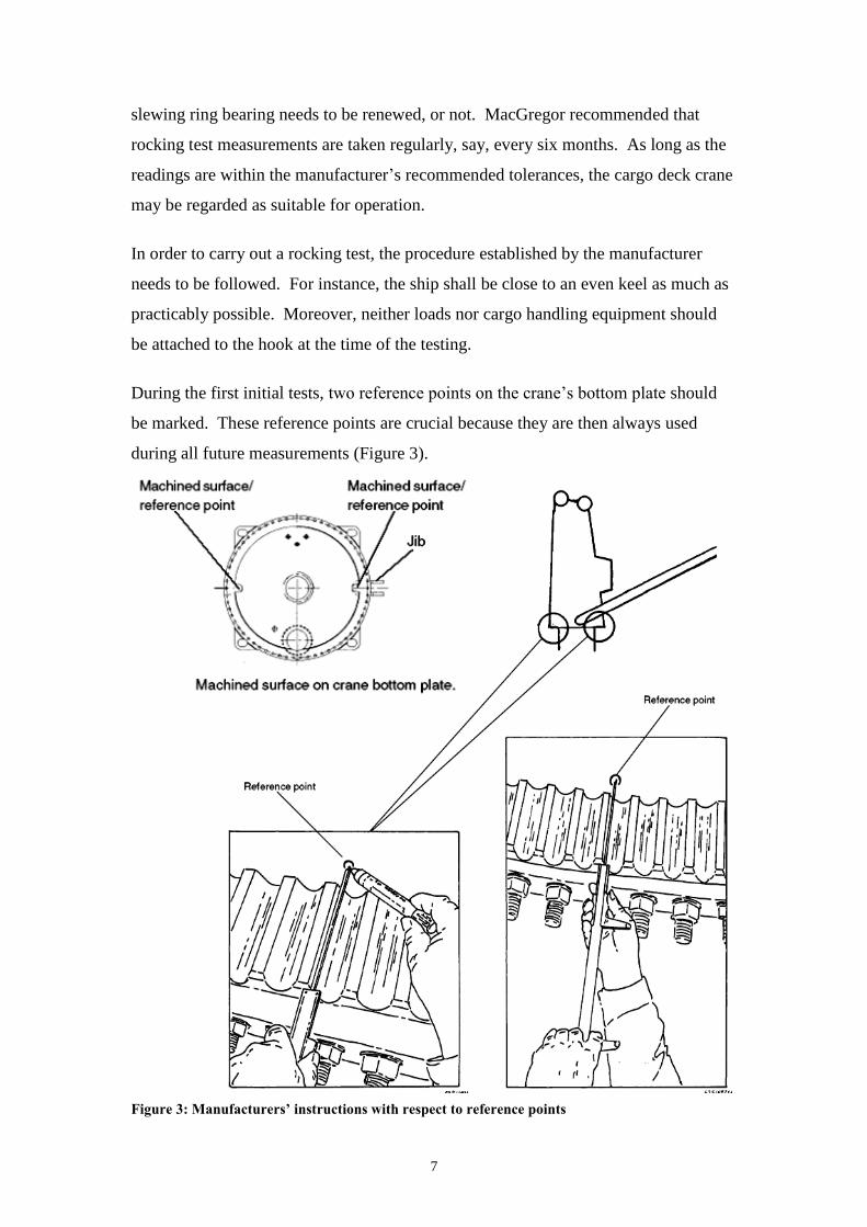
During the first initial tests, two reference points on the crane’s bottom plate should
be marked. These reference points are crucial because they are then always used
during all future measurements (Figure 3).
Figure 3: Manufacturers’ instructions with respect to reference points

8
Accurate results necessitate that measurements are taken at four positions on the
slewing ring bearing. The first position to be tested is with the crane at maximum
outreach (Figure 4). At this stage, two measurements are taken at specific points
labelled ‘B’ and ‘A’.
Figure 4: Measuring points with an extended jib
The jib is then operated to the next position, i.e., at the minimum horizontal reach
(Figure 5), where a single reading labelled position ‘C’ is taken. The manufacturers
highlight the importance of using a measuring device with an accuracy of not less
than 0.1 mm.
Figure 5: Measuring points with jib at minimum outreach

9
The manufacturer’s manual specifies that the difference between readings taken at
points ‘B’ and ‘A’ shall not exceed 7.0 mm, whereas the difference in readings
between points ‘C’ and ‘B’ should not exceed 3.0 mm. It is further specified that if
either of these measurements is exceeded, the deck crane shall not be operated.
The procedure of measurement in both conditions should be repeated with the crane
facing the forward, aft, starboard and port sides.
Precautions, which need to be noted include:
all the readings are always taken from the same point location to ensure
accurate analysis;
consider a wrong reading if the difference between the readings taken at points
‘B’ and ‘C’ is less than or equal to zero.
1.6 Narrative2
On 29 December 2016, Trapezitza left the port of Berdyansk, Ukraine, with 1,836 mt
of sea salt in all her cargo holds, drawing a mean draught of 4.46 m. The voyage was
uneventful and the vessel arrived at the port of Damietta, Egypt on the 21 January
2017 at about 1515. The vessel intended to load more cargo at this port.
Cargo was delivered to the ship by trucks. A bulldozer on the quay piled up the cargo
to facilitate the grabbing process carried out with a clamshell grab. The loading was
carried out by three gangs in cargo holds nos. 1, 3 and 5. During the cargo operation,
the master noticed that cargo deck cranes nos. 1 and 2 were operating slower than
cargo deck crane no. 3. Concerned that this may affect the vessel’s trim (by the
stern), the master instructed the chief mate to monitor the trim and ensure that it
remains within the agreed parameters.
At 0010 (22 January), without any warning, cargo deck crane no. 1’s upper post
collapsed onto the quay, making contact with the open cargo hatch cover of cargo
hold no. 5 as it came down. The cargo deck crane pedestal remained intact (Figure 6).
2 Unless otherwise stated, all times in this report are local time.

10
Figure 6: Deck crane no. 1 after collapsing to the quay
No injuries were reported and immediate action was taken to ensure that no hydraulic
leaks had occurred. The electrical supply to the cargo deck crane was interrupted and
the driver was assisted out of the cabin. No injuries were reported and the loading
operations came to a halt.
At the time of the accident, the master was in his cabin but felt the vibrations, which
reportedly were also felt throughout the ship. From the port hole, he observed a
number of stevedores boarding the vessel. Soon after, the third mate informed him of
the accident. The master made his way quickly to the main deck to observe more
closely and decide on further actions.
A restriction zone was enforced around the perimeter of cargo hold no. 1. Eventually,
a mobile crane was positioned on the quay to lift the damaged cargo deck crane. The
collapsed part of the cargo deck crane was repositioned on the main deck, on port
side, enabling the cargo loading operations to resume.

11
1.7 Damage to the Vessel and Fittings
It was immediately evident that the slewing ring bearing was damaged. No damages
were reported to the hull, deck plating, cargo holds closing appliances and vent heads.
The only reported damage (apart from the cargo deck crane), where the deck railings
where the jib fell onto the main deck and overside.
1.8 Similar Accidents on Board
Records showed that in 2011, Trapezitza had a similar accident on cargo deck crane
no. 3. The Company advised that as a preventive action, more frequent rocking tests
had been required.

12
2 ANALYSIS
2.1 Purpose
The purpose of a marine safety investigation is to determine the circumstances and
safety factors of the accident as a basis for making recommendations, to prevent
further marine casualties or incidents from occurring in the future.
2.2 Cause of the Accident
Evidence indicated that the immediate cause of the accident was a catastrophic failure
of the slewing ring bearing. The outer and inner parts of the slewing ring bearing
separated when the jib was extended to the port side while lifting the cargo from the
jetty due to excessive wear and tear in the raceways Figures 7a and 7b).
Figures 7a and 7b: Photos showing excessive bearing wear
As the slewing ring bearing separated and the ball bearings fell out of the raceways,
the jib and the cabin separated from the pedestal.

13
2.3 Cause of the Slewing Ring Bearing Failure
The safety investigation is of the view that the wear and tear on the outer slewing ring
bearing may have been the initiating factor leading to its failure.
The engineering laboratory report revealed two main sources of wear present in the
inner ring of the slewing ring bearing. The first source was the high amount of non-
metallic oxide inclusions (Figures 8a and 8b), suggesting an increased contamination
of undesired bearing elements.
Figures 8a and 8b: Non-metallic oxide inclusion found in the inner and outer rings
The other source of wear present in the slewing ring bearing was the low plasticity
and impact toughness of the steel of the outer ring. These were found to be below the
standard requirements (DIN EN 10083-3:2007-01) on steels for quenching and
tempering. The results yielded by the analysis and comparison with the required
average value have been tabulated in tables 2 and 3.

14
Table 2: Outer slewing ring bearing
No. Tested probes Measured values of the controlled
parameters
Position
relative to
the axis of
the forging
Temperature Cross section
cm
Impact
energy
KV, J
Impact
toughness
KCV, Jcm-2
Note
1 Across + 20 °C 0.826 x 0.993 41.2 50.2 -
2 0.821 x 0.993 45.1 55.4 -
3 0.822 x 0.993 30.4 37.3 -
Measured (average) 38.9 47.6 -
4 Across - 20 °C 0.820 x 0.993 11.8 14.5 -
5 0.822 x 0.993 16.7 20.4 -
6 0.821 x 0.996 27.5 33.6 -
Measured (average) 18.7 22.8 -
Required:
steel brand 42 CrMo4, DIN EN 100083-3:2007-01
35
Table 3: Inner slewing ring bearing
No. Tested Probes Measured values of the controlled
parameters
Position
relative to
the axis of
the forging
Temperature Cross section
cm
Impact
energy
KV, J
Impact
toughness
KCV, Jcm-2
Note
1 Across + 20 °C 0.825 x 0.994 54.9 67.0 -
2 0.821 x 0.990 62.8 77.2 -
3 0.825 x 0.992 83.4 101.9 -
Measured (average) 67.0 82.0 -
4 Across - 20 °C 0.823 x 0.994 45.1 55.2 -
5 0.824 x 0.993 34.3 42.0 -
6 0.823 x 0.993 45.1 55.2 -
Measured (average) 41.5 50.8 -
Required:
steel brand 42 CrMo4, DIN EN 100083-3:2007-01
35

15
Analysis of the inner and outer slewing ring bearing at the engineering laboratory
showed that both rings had a deformed toroid groove (Figure 9). It was also revealed
that the deformation in the outer ring was not complete but only present round half of
the ring, whereas for the inner ring, the crown gear remained non-deformed.
Figure 9: Cross-sectional view of inner and outer bearing showing toroidal wear
Even more, the laboratory analysis of the fracture on the surface of the toroid groove on both
rings indicated that the ball bearings’ contact with the rings was not centred due to the
presence of unacceptable deformation of the bearings (Figure 10).

16
Figure 10: Deformation causing wear on ball bearings at the outer ring
The ball bearings were worn out mainly through a toroidal strip round one axis
(Figure 11) due to lack of normal rolling. This may have been caused by the wear in
the slewing bearing rings. It has been therefore concluded that the wear of the balls
was due to the sliding and blocking against the grooves over time (Figure 11).
Figure 11: Excessive wear patterns
Spalling of the outer slewing ring bearing would have created excessive amounts of
debris in the bearing grease. The contaminated grease would have then migrated
throughout the bearing assembly as a result of the general rotation during cargo
operations. It has therefore been concluded that operation of the ball bearings over
the contaminated lubrication accelerated the spalling observed on either side of the
soft zone in the outer bearing radial housing.
17
2.4 Slewing Bearing Design and Testing
2.4.1 Interpretation of the rocking test results
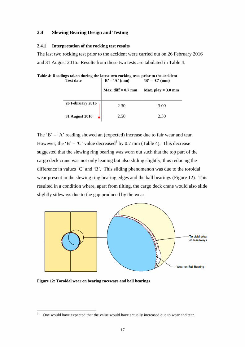
The last two rocking test prior to the accident were carried out on 26 February 2016
and 31 August 2016. Results from these two tests are tabulated in Table 4.
Table 4: Readings taken during the latest two rocking tests prior to the accident
Test date ‘B’ – ‘A’ (mm)
Max. diff = 0.7 mm
‘B’ – ‘C’ (mm)
Max. play = 3.0 mm
26 February 2016 2.30 3.00
31 August 2016 2.50 2.30
The ‘B’ – ‘A’ reading showed an (expected) increase due to fair wear and tear.
However, the ‘B’ – ‘C’ value decreased3 by 0.7 mm (Table 4). This decrease
suggested that the slewing ring bearing was worn out such that the top part of the
cargo deck crane was not only leaning but also sliding slightly, thus reducing the
difference in values ‘C’ and ‘B’. This sliding phenomenon was due to the toroidal
wear present in the slewing ring bearing edges and the ball bearings (Figure 12). This
resulted in a condition where, apart from tilting, the cargo deck crane would also slide
slightly sideways due to the gap produced by the wear.
Figure 12: Toroidal wear on bearing raceways and ball bearings
3 One would have expected that the value would have actually increased due to wear and tear.
18
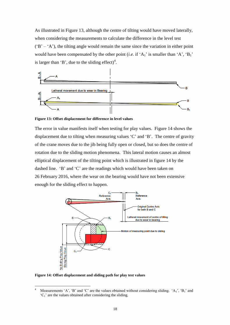
As illustrated in Figure 13, although the centre of tilting would have moved laterally,
when considering the measurements to calculate the difference in the level test
(‘B’ – ‘A’), the tilting angle would remain the same since the variation in either point
would have been compensated by the other point (i.e. if ‘A1’ is smaller than ‘A’, ‘B1’
is larger than ‘B’, due to the sliding effect)4.
Figure 13: Offset displacement for difference in level values
The error in value manifests itself when testing for play values. Figure 14 shows the
displacement due to tilting when measuring values ‘C’ and ‘B’. The centre of gravity
of the crane moves due to the jib being fully open or closed, but so does the centre of
rotation due to the sliding motion phenomena. This lateral motion causes an almost
elliptical displacement of the tilting point which is illustrated in figure 14 by the
dashed line. ‘B’ and ‘C’ are the readings which would have been taken on
26 February 2016, where the wear on the bearing would have not been extensive
enough for the sliding effect to happen.
Figure 14: Offset displacement and sliding path for play test values
4 Measurements ‘A’, ‘B’ and ‘C’ are the values obtained without considering sliding. ‘A1’, ‘B1’ and
‘C1’ are the values obtained after considering the sliding.

19
‘B1’ and ‘C1’ represent the possible measured values, which would have been taken
on 31 August 2016. In this case, the sliding motion would have been more
pronounced. Although ‘B’ – ‘C’ is larger than ‘B1’ – ‘C1’, in reality the wear in the
play would have increased.
2.4.2 Measurement taking during rocking test
As mentioned in section 1.5.3.2, the rocking test is normally done using a Vernier
calliper and the dimensions are measured from pre-designated locations. Considering
the environment where the measurement is being taken, this method may be subject to
numerous flaws. Of most concern is the fact that the measuring points are located in a
confined space of not more than two meters in diameter and without any natural light
(Figure 15).
Figure 15: Location of rocking test measuring points inside the crane pedestal (lighting provided
by camera flash)
These conditions may result in either the crew member positioning the measuring
instrument improperly while taking measurements, or read the dimensions incorrectly
because of inadequate artificial lighting5.
5 A more specialised tool, incorporating pre-designated mounting points (which could be covered
during the measurement would prevent dirt and dust from altering dimensions) would have been
more ideal. Moreover, this would ease the measuring process as the jig would be simply mounted
into place, thereby eliminating the possibility of incorrect measurement.

20
2.4.3 Grease test
On 02 December 2016, greasing of the slewing ring bearing was done by the crew
members. Since the rocking test results were within acceptable parameters (Table 4),
it was not deemed necessary to perform grease sampling for particle consistency.
Visually, the crane showed no signs of any wear in the mechanism. An analysis of
the quality of grease in the slewing ring bearing would have probably detected
abnormal wear from particle containment in grease due to the excessive wear.
Gard-Loss Prevention Circular No. 11-08, explains that analysis of grease quality can
prevent premature failure of machinery and bearings and that such analysis does not
have to necessarily be a laboratory analysis.
2.4.4 Metallurgical quality of bearing steel
The metallurgical quality of bearing steel is related to both its harmful purity in
sulfides, nitride inclusions, and especially hard-to-deform globular oxide inclusions.
The work of bearings is characterized by high local loads and hence, stringent purity
requirements for non-metallic inclusions. In cases where the slewing ring bearing has
a high content of oxide inclusions, a decrease in the fatigue fracture resistance and the
life-time threshold of the bearing will be experienced. The lifetime of the bearing
depends on a number of factors, including, the size of non-metallic inclusions; the
larger the inclusion size, the shorter the lifetime.
2.5 Missing Cues
As indicated elsewhere, the safety investigation believes that there were at least three
instances which may have provided potential cues on the condition of the slewing ring
bearing, but which were missed. These were:
1. metal fragments in the grease sample;
2. the February and August rocking tests results; and
3. the slower operating speed of deck crane no. 1.
This compromised the risk identification and its management.

21
The MSIU believes that there were a number of reasons as to why these cues had been
missed. It would appear that the results of the rocking tests (which fell within the
maximum play limit established by the manufactures), had misled the crew members
in believing that the deck crane remained safe to operate. The (apparent) reduction in
slewing ring bearing play did not cause any concern to the crew member, whose main
criterion was that the play did not exceed 3.0 mm.
Then, in the absence of any mishap, the crew members had no reason to delve deeper
into the issue – actually, there was no reason to believe that there was an issue at all.
It was clear that the grease test was not considered to be necessary because the results
of the rocking tests were deemed to be a good enough indication that the slewing ring
bearing was operating within the maximum limits established by the manufacturer.
The manufacturer’s manual emphasised that rocking tests were more of an indicative
result of the slewing ring bearing condition, compared to the grease sample test.
However, both tests were not intended by the manufacturer to be considered as
mutually exclusive. Rather, the manufacturer specified that both the rocking test and
the grease sample test together would provide the best basis for evaluation of the
slewing ring bearing condition.
The slower speed of deck cargo crane no. 1 was also not attributed to possible issues
with the slewing ring bearing. As such, the master had observed two cranes which
were operating at a low speed. Per se, that may have reinforced the belief that the low
operating speed was due to one other crucial variable, i.e., the inexperienced crane
operators rather than a possible mechanical issue. As much as this was the only
possible cue that would have indicated a potential problem in the hours prior to the
accident, it has to be clarified that that would have been a very weak cue and not
strong enough to be immediately captured by any of the crew members.
In the absence of such information (because of missing the cues), the crew members
had a less rich mental model of the precarious mechanical condition of the cargo deck
crane and hence, had no reason to conduct a systematic analysis of the risks involved
in operating it. In actual fact, on the basis of the information available (which
suggested that the tolerances had not been exceeded), the crew members had no
reason to express any concern. The feedback from the prevailing context indicated no

22
particular hazards, which would have warranted drastic measures, such as, for
instance, suspending the loading operations or using a shore crane.
It was therefore clear that the decision to operate the cargo deck cranes had been
immediately conditioned by the available data and what seemed to be a normal
operation of the deck machinery, has actually ended in significant damages.

23
THE FOLLOWING CONCLUSIONS, SAFETY
ACTIONS AND RECOMMENDATIONS SHALL IN NO
CASE CREATE A PRESUMPTION OF BLAME OR
LIABILITY. NEITHER ARE THEY BINDING NOR
LISTED IN ANY ORDER OF PRIORITY.

24
3 CONCLUSIONS
Findings and safety factors are not listed in any order of priority.
3.1 Immediate Safety Factor
.1 The outer and inner part of the slewing ring bearing separated when the jib
was extended to the port side while carrying a load, due to excessive wear and
tear in the raceways.
3.2 Latent Conditions and other Safety Factors
.1 The slewing ring bearing was contaminated with high amount of non-metallic
oxide inclusions;
.2 The low plasticity and impact toughness of the steel of the slewing bearing
outer ring was also a source of contamination;
.3 The inner and outer slewing ring bearing had a deformed toroid groove,
causing the ball bearings’ contact with the rings not being centred due to the
presence of unacceptable windage and deformation of the bearings;
.4 The wear on the ball bearings contributed to wear on the slewing ring bearing;
.5 Spalling of the outer slew bearing ring would have created excessive amounts
of debris in the bearing grease;
.6 Operation of the ball bearings over the contaminated lubrication accelerated
the spalling observed on either side of the soft zone in the outer bearing radial
housing;
.7 The rocking test results were interpreted to mean that the play in the slewing
ring bearing was within maximum tolerances;
.8 No grease sample analysis had been carried out because the play in the slewing
ring bearing was considered to be within the maximum tolerances;
.9 The fatigue fracture resistance and the life-time threshold of the slewing ring
bearing had been compromised because of the contaminated grease;

25
.10 The crew members had a less rich mental model of the precarious mechanical
condition of the cargo deck crane and hence, had no reason to conduct a
systematic analysis of the risks involved in operating the deck crane;
.11 The decision to operate the cargo deck cranes had been immediately
conditioned by the available data and what seemed to be a normal operation of
the deck machinery, has actually ended in significant damages.
4 SAFETY ACTIONS
During the course of the safety investigation, the Company took the following safety
actions:
1. Grease samples will be tested every six months and this requirement has been
included in the vessel’s PMS;
2. A Technical Circular addressing rocking tests and grease sampling, has been
sent to all vessels in the Fleet;
3. Enhance information in the vessel’s PMS on ship’s cranes checks,
measurements and maintenance jobs;
4. Discussion of this accident during shore-held monthly seminars and pre-
boarding briefings of chief engineers.


![Untitled-1 []...months months months months](https://img.dokumen.tips/doc/110x75/60cc6a9b3d3a423bd0058c49/-untitled-1-months-months-months-months.jpg)

