Embed Size (px)
Citation preview

1
Transport of variable-density solute plumes in beach aquifers in
response to oceanic forcing
R. Bakhtyar a,b,c
, A. Brovelli c, D.A. Barry
c, C. Robinson
d, L. Li
e
a Present
address: Department of Environmental Sciences and Engineering, The University of North Carolina,
Chapel Hill, NC 27599-7431, USA. Email: [email protected]
b Present address: Coastal and Hydraulics Laboratory, US Army Engineer Research and Development Center,
Vicksburg, MS 39180-6133, USA
c Laboratoire de technologie écologique, Institut d’ingénierie de l’environnement, Faculté de l’environnement
naturel, architectural et construit (ENAC), Station 2, Ecole polytechnique fédérale de Lausanne (EPFL), 1015
Lausanne, Switzerland. Emails: [email protected], [email protected]
d Department of Civil and Environmental Engineering, University of Western Ontario, London, Ontario N6A
5B9, Canada. Email: [email protected]
e School of Civil Engineering, University of Queensland, St. Lucia, Queensland 4072, Australia. Email:
Published: Advances in Water Resources, 2013
Author to whom all correspondence should be addressed. Ph. +1 (919) 525-6217, Fax. +1 (919) 966-7115

2
ABSTRACT: A comprehensive numerical study was undertaken to investigate transport of a variable-
density, conservative solute plume in an unconfined coastal aquifer subject to high and low frequency
oceanic forcing. The model combined variable-density saturated flow for groundwater and solute
transport, and wave hydrodynamics from a 2D Navier-Stokes solver. A sinusoidal tidal signal was
specified by implementing time-varying heads at the seaward boundary. The solute plume behavior
was investigated under different oceanic forcing conditions: no forcing, waves, tide, and combined
waves and tide. For each forcing condition, four different injected solute densities (freshwater, brackish
water, seawater, brine) were used to investigate the effects of density on the transport of the injected
plume beneath and across the beach face. The plume’s low-order spatial moments were computed, viz.,
mass, centroid, variance and aspect ratio. The results confirmed that both tide- and wave-forcing
produce an upper saline plume beneath the beach face in addition to the classical saltwater wedge. For
the no-forcing and tide-only cases (during rising tides), an additional small circulation cell below the
beach face was observed. Oceanic forcing affects strongly the solute plume’s flow path, residence time
and discharge rate across the beach face, as well as its spreading. For the same oceanic forcing, solute
plumes with different densities follow different trajectories from the source to the discharge location
(beach face). The residence time and plume spreading increased with plume density. It was concluded
that simulations that neglect the effect of waves or tides cannot reproduce accurately solute plume
dispersion and also, in the case of coasts with small waves or tides, the solute residence time in the
aquifer.
Keywords: Contaminant transport; Conservative tracer; Density-driven circulation; Hydrodynamics;
High and low frequency motions; Coastal aquifer; Variable-density groundwater

3
Abbreviations
HT High Tide
LT Low Tide
NS Navier-Stokes
RANS Reynolds-Averaged Navier-Stokes
SWL Still Water Level
TKE Turbulent Kinetic Energy
VOF Volume-Of-Fluid
Symbols
Variable Description Dimensions
A tidal amplitude L
C concentration M L-3
htide time-varying tidal head L
hf equivalent freshwater head L
H water wave height L
Kf hydraulic conductivity L T-1
k turbulent kinetic energy L2
T-2

4
L model domain length L
m normalized solute mass in the aquifer -
M0 zero-order moment M
M1 first-order spatial moment L
M11 covariance L2
M2 second-order spatial moment L2
t time T
T wave period T
x, z horizontal and vertical directions, respectively L
Greek
ε turbulence dissipation rate L2
T-3
σ covariance tensor L2
ρ fluid density M L-3
ρP solute plume density at the point of injection M L
-3
ω tidal angular frequency T-1

5
1. Introduction
Groundwater quality in nearshore aquifers is affected by seawater intrusion (e.g., [1,2]), as well as
localized contamination due, for example, to accidental pollutant discharges from urban areas,
industrial plants and landfills located near the shoreline (e.g., [3-5]). Nearshore groundwater processes,
including tides, waves and changes in groundwater conditions arising from pumping and climatic
stresses, play an important role in the exchange of solutes across the aquifer-ocean interface [6-8].
The influence of tidal effects on saltwater intrusion and nearshore aquifer dynamics has been
studied thoroughly (e.g., [6,9-15]). Four approaches have been used to investigate groundwater flow
and transport processes driven by tidal forcing: (i) field experiments [9]; (ii) laboratory measurements
[6,15]; (iii) analytical models [16]; and (iv) numerical simulations [12,13,17,18]. Tides control the
salinity distribution in the nearshore aquifer, affect the shape and position of the intruding saltwater
wedge, as well as modify groundwater flow patterns (e.g., [4,13,19-24]). Robinson et al. [11] explored
salt-freshwater mixing in a nearshore aquifer subject to tidal forcing and found that the tide-induced
flows and saltwater transport leads to the formation of an upper saline plume over discharging fresh
groundwater. This was shown to enhance salt-freshwater mixing.
Studies have examined the extent to which tide-induced circulation affects also solute fate in
nearshore aquifers. Two scenarios can be distinguished. In the first, solutes are released in the open
water (i.e., offshore) and reach the beach face through oceanic currents and waves, such as in the case
of accidental oil spills (e.g., [25-27]). The second scenario considers the case of land-derived solutes
released onshore, near the coastline. In particular, Zhang et al. [28,29], Boufadel et al. [6,30] and
Brovelli et al. [17], through laboratory tank experiments and numerical modeling, examined the effects
of tides on variable-density solute plumes. They observed that the solute mostly discharged across the
beach face, but that tides influence the shape and spreading of the plume. Increased solute spreading

6
due to oceanic fluctuations was also confirmed by Elfeki et al. [31]. Robinson et al. [12] showed that
tidal circulation increases dissolved oxygen availability in the sediments and therefore may promote
oxidation of pollutants prior to discharge. It can be concluded that (i) tidal forcing modifies the rate of
discharge of conservative solutes; (ii) the salinity distribution near the shoreline is controlled by the
tidal amplitude and regional hydraulic gradient, and (iii) tide-induced groundwater circulation near the
beach face leads to the formation of an upper saline plume in addition to the lower saltwater wedge.
In addition to the influence of tides on nearshore groundwater dynamics, wave effects need to be
accounted for [32]. The exchange of fluid across the beach face during each wave period influences
circulation patterns and the salinity distribution, which could affect solute transport in the aquifer
[10,33]. Wave run-up increases saltwater infiltration through the beach face, which creates a mixing
zone (upper saline plume) beneath the beach face [4,7,22]. Recently, Xin et al. [8] examined the
individual and combined effects of waves and tides on groundwater flow and saltwater transport in a
nearshore aquifer. They combined SUTRA [34], a variably saturated groundwater flow model, with
BeachWin [35], to simulate the effects of linear incoming waves. They observed that coupled tides and
waves increase the circulation of pore-water (circulation of seawater or circulation of land-derived
pore-water), enhancing the width and thickness of the upper saline plume. BeachWin is based on the
depth-integrated shallow water flow equations and cannot simulate the complex flow, turbulence fields
and vertical velocities that may affect wave-induced fluxes across the beach face [7].
The objective of this study is to analyze the effect of oceanic fluctuations (high- and low-
frequency ocean forcing, i.e., waves and tides, respectively) on the fate of solutes released in a
nearshore aquifer. Simulation results for simplified conditions (e.g., no fluctuations or tide-only) are
compared with those obtained under more complex conditions where all forcing are considered. This
enables identification of conditions for which the effect of oceanic fluctuations can be neglected. The

7
simulations are pertinent to polluted water that is released into the aquifer near the shoreline, such as in
the case of septic tanks, industrial plants or landfills (e.g., [3,5,36]). Contaminated waters can be denser
than ambient freshwater, which results in more complex transport pathways [17,29]. For this reason,
the simulations presented here consider density differences between the ambient water and injected
solute plume in addition to the density effects between the ambient groundwater and circulating
saltwater. The model has not been validated against experimental data for the conditions considered in
this manuscript since suitable data sets are not available. But, the predictive capabilities of the each
sub-module have been tested previously (i.e., [12,17,37,38]) and good agreement was found
considering different conditions. Thus, we believe that the model used in this study is to some extent
validated.
2. Methodology
Bakhtyar et al. [37-39] developed a 2D (cross-shore) numerical study to simulate water flow in the
surf and swash zones as well as in the nearshore aquifer. Fluid motion in the ocean was simulated using
the Navier-Stokes (NS) equations. Comparison of model predictions with experimental data on wave-
induced watertable fluctuations, sediment transport and beach profile changes indicated that the model
is well suited to simulate the effect of incoming waves on in/exfiltration fluxes across the beach face.
The main features of the numerical study are summarized in the following.
2.1. Variable-density groundwater flow and transport model
SEAWAT Version 4 [40] was used to simulate variable-density groundwater flow and solute
transport in a nearshore aquifer subject to dynamic fluctuations at the seaward boundary. SEAWAT is a
variable-density saturated flow model based on the equivalent freshwater head formulation that couples
MODFLOW-2000 [41] for groundwater flow with MT3DMS v. 5.0 [42] for solute transport.

8
The groundwater flow and solute transport model was first run using a static sea level (Still Water
Level, SWL) to obtain the steady-state groundwater heads and salt distribution. Following [17], the
nearshore free-water zone (the sea) was approximated in SEAWAT using a fictitious medium with a
high hydraulic conductivity (106
m d-1
). A constant head condition was set on the seaward and
landward boundaries, while an impermeable no-flow boundary was assumed along the bottom
boundary (Fig. 1).
2.2. Modeling of oceanic fluctuations
The effect of wave motion on the nearshore aquifer dynamics was simulated following [38,39].
The 2D RANS wave-motion model of [37,43] was used to simulate the seawater elevation above the
beach face resulting from the oceanic waves. The model combines the continuity and momentum
formulation of the incompressible NS equations with a k-ε turbulence closure and VOF technique. The
generating-absorbing boundary condition was used at the offshore boundary to generate incoming
waves while adsorbing reflected waves [43-45].
Coastal hydrodynamics were linked to the aquifer at the beach face. Head boundary conditions
were applied at the beach face (in the free-water section of the domain) and directly above the
watertable (in the aquifer). The head at the boundary, which accounted for both waves and tides, was
computed with:
( ) ( ) cos ω ,tot waveh t h t A t (1)
where htot is total head (sum of wave and tide heights), hwave is the elevation of the sea surface
computed using the NS solver, t is time, A is the tidal amplitude and ω is the tidal angular frequency. In
the simulations with the tide only, hwave was replaced by the SWL. For the case of combined waves and
tides, the wave signal was computed assuming a constant SWL in the NS solver.

9
For the simulations with oceanic forcing, the steady-state head and salt distributions were used as
initial conditions and a time-variable head boundary (CHD-MODFLOW package) was applied at the
seaward boundary. The entire simulation length was subdivided into multiple stress-periods. For each
period, the initial and final sea elevations were calculated using the wave- and tide-motion simulators.
Stress periods were divided further into time steps within SEAWAT using a constant head for each
time step, computed as a linear interpolation between the initial and final head of the current stress
period.
MODFLOW (and consequently SEAWAT) does not consider flow in the unsaturated zone. In this
model, cells are de-activated if they are not fully saturated and if their bottom is below the watertable
elevation. Due to the use of dynamic boundary conditions (tides and waves), the watertable elevation
changes with time, therefore cells are deactivated while the watertable elevation is decreasing (e.g.,
during falling tides and wave backrush) and are re-activated as the watertable rises again (rising tide
and wave runup). In MODFLOW, the re-wetting package was used to check at each time step which
dry cells should become active. This introduces some non-linearities in the flow equations and
significantly increases the computation time. A different but related problem rises with boundary
conditions. Obviously, head boundary conditions can only be applied to a cell that is active at the
beginning of a stress period. During the rising tide, at a specific location the head at the beginning of
step i is higher than the head at the previous stress period (i -1). Therefore, at the beginning of period i
the cell to which the boundary should be applied is inactive, because during the previous stress period
the watertable elevation was lower than the elevation of the cell’s bottom. In this case, the boundary
condition is applied to a lower cell, permitting the re-wetting package to reactivate cells as they become
saturated. This introduces some localized temporary artifacts in the flow field (i.e., cells that are in the
saturated zone become sources of water).

10
2.3. Model setup
Numerical experiments similar to those of [39] were conducted, the major difference being that the
groundwater flow model was extended landward to simulate the solute and salt transport in the aquifer
and to decrease the influence of the landward boundary condition. A schematic of the model set-up and
properties is provided in Fig. 1. Below, we refer to the injected contaminant as the solute plume.
Simulations were conducted for four different oceanic forcing conditions: (i) no oceanic forcing
(i.e., density and hydraulic gradient-driven flow only), (ii) tide, (iii) waves, and (iv) combined waves
and tide. We considered four different densities of the injected solute plume: (i) same as the ambient
groundwater (freshwater), (ii) between freshwater and seawater (brackish), (iii) same as seawater
(saltwater) and (iv) higher than seawater (brine). A small-scale field setup was used in this study.
Therefore, the typical wave heights (~50 cm) and wave periods (between 5 and 10 s), and micro-tides
amplitude (1 m) were set to simulate the wave motions for such experiments. Table 1 summarizes the
properties of the 16 cases considered.
The numerical computations were stopped if there was no improvement in the head and salt-
water wedge for two consecutive time steps. The computed steady-state groundwater flow and salt
distributions in the coastal aquifer were used as initial conditions for the subsequent simulations. Then,
the solute was injected and simulations were run until the solute was discharged from the aquifer (a
residual tracer mass < 0.5% of the injected mass was the threshold for ending the simulation).
Simulations with waves only were conducted using a phase-resolving approach (i.e., the full wave
cycle was simulated spatially and temporally). For the groundwater flow, each 7-s wave period was
divided in 14 equal stress periods (refers to periods over which the aquifer’s boundary conditions are
constant) to capture the head changes above the beach face and seawater infiltration/exfiltration. The

11
phase-resolving approach is more accurate but computationally demanding. Numerical experiments
showed that the combination of waves and tides could not be simulated using the same methodology
due to (i) the excessive computational demand and (ii) the changing watertable position due to the
oceanic forcing (tides, in particular). With respect to the watertable position, within SEAWAT a fixed
head condition must be applied above the watertable (and not on the beach face). The location of the
watertable is however not known a priori and does not necessarily follow a predictable pattern, and so
the phase-resolving approach could not be applied. The phase-averaged approach (results are an
average of a wave) of [8] was therefore used. This approach is also much less computationally
demanding. Xin et al. [8] compared the pseudo-steady state salt distribution and aquifer circulation
obtained using the phase-resolving and phase-averaged approaches. They found similar results for the
two cases and concluded that the main effect of waves on the circulation in the nearshore aquifer is due
to wave setup, a feature that is retained by the phase-averaged simulations. Physically, their finding is
expected since the groundwater flow driven by a rapidly fluctuating periodic boundary condition (i.e.,
waves) is small and constrained to locations very close to the beach face. The cumulative aquifer
response occurs over longer periods and these are well characterized by the phase-averaged approach.
This observation corresponds to using wave setup to simulate local flow beneath a beach face [46].
2.4. Metrics for solute migration
To compare the behavior of the solute plume between the different cases, the solute plume was
characterized by computing the time-evolution of its spatial moments and covariance tensor (e.g., [47]).
The total plume variance was computed as the trace of the covariance tensor, which is independent of
the coordinate orientation. The total variance is an indication of aquifer water-solute mixing and
spreading. The solute discharge rate across the beach face was estimated from the time derivative of the
zero-order moment, and the aspect ratio of the plume was defined as the ratio of the second central

12
moments (computed along the plume’s principal axes). Expressions for calculation of these moments
are given in the Appendix. The total mass and discharge rate were normalized by the maximum mass in
the aquifer to facilitate comparison of the different cases.
3. Results
In §3.1, the simulated solute plume with different densities and groundwater flow and transport
dynamics in the absence of oceanic forcing are presented (Cases 1-4, Table 1). Groundwater flow
patterns, and the simulated solute plumes (with different densities) under tidal forcing (Cases 5-8,
Table 1), wave forcing (Cases 9-12, Table 1), and combined wave and tide forcing (Cases 13-16, Table
1) are presented in §3.2, 3.3 and 3.4, respectively.
3.1 No oceanic forcing
Figure 2 shows that, in absence of tides and waves, the classical saltwater wedge forms with the
density difference between ambient groundwater and seawater driving the recirculation of seawater
through the aquifer. Streamlines can be divided into two parts: seawater recirculation through the
saltwater wedge and discharge of ambient groundwater.
The 0.25C0 (where C0 is the initial tracer concentration) contour shows the location of the (dense)
solute plume (case 4) in the aquifer. Initially (panel a), the plume deflects the shallow flow streamlines,
and the ambient groundwater discharges mostly above or near the SWL on the beach face. Deeper
streamlines are not noticeably affected by the plume and their discharge occurs near the fresh/saltwater
interface.
Within the seawater wedge, density-driven flow triggers a small circulation cell below the beach
face (at a distance of about 25 m). As the tracer plume approaches the fresh/saltwater interface (panel
b), the wedge steepens and the circulation cell below the beach face develops further. The presence of

13
the dense plume modifies the freshwater streamlines and as a result the location where land-derived
solutes are discharged. When the plume contacts the seawater wedge, it merges and becomes part of it
(panels c and d). At this stage, the plume and seawater wedge form a single body of water with density
higher than ambient freshwater, which modifies the circulation near the aquifer/seawater wedge
interface. This can be deduced from the shape of the streamlines in this region: normally they follow
closely the sea/freshwater interface (panels a and b), but when the plume ‘touches’ the seawater wedge
(panels c and d), streamlines bend and cross the seawater interface, following the plume/freshwater
(compare panels b and d). Compared with the case without the dense solute plume (i.e., freshwater), the
circulation patterns are profoundly modified (results not shown).
The circulation cell below the beach face eventually occupies more than half the thickness of the
aquifer (panel c, ~27 m), and streamlines in the tracer plume are much steeper. The plume and seawater
interface (dispersion zone) partially overlap. Streamlines in the freshwater aquifer (landward) are no
longer affected by the dense plume. As the plume touches the beach face, the solute is progressively
discharged and the tracer mass in the aquifer decreases.
The migration of the solute plume (different densities, Table 1) in the nearshore aquifer without
oceanic forcing is illustrated in Fig. 3. Results are reported after 10, 20 and 30 d. The plume migration
is controlled by the regional groundwater hydraulic gradient and the density contrast between the
ambient freshwater and the solute plume [11]. Each plot in Fig. 3 also shows the location of the salt-
freshwater interface, as given 0.5 normalized seawater salt concentrations. As the density of the solute
plume increases, the plumes show greater vertical spreading and also alter the position and shape of the
saltwater wedge (cf. Fig. 2). The higher density plumes cause steepening and a seaward migration of
the salt-freshwater interface with the interface steepness increasing with solute plume density. Below,

14
subsequent simulations with oceanic fluctuations are compared with these results to identify the effects
of waves and tides.
The plume’s spatial moments in the coastal aquifer for cases 1-4 are shown in Fig. 4. Results are
shown for the time variation of the zeroth moment (total mass), first spatial moment (centroid), aspect
ratio (calculated along the plume’s principal directions) and total plume variance. The time when 80%
of the solute mass was removed (i.e., t80, referred to as the residence time) was also calculated. This
time corresponds to the intersection between the zeroth spatial moment and the horizontal dashes in
Fig. 4a. The moment analysis indicates that plume density influences its residence time and spreading
characteristics (Table 2 and panels a, c and d of Fig. 4). In all cases, the plume variance does not vanish
at long times because a small (less that 0.1%) amount of solute remained in the aquifer when the
simulations were halted.
When the density contrast is negligible or small (fresh and brackish water), the horizontal
groundwater flow driven by the regional hydraulic head gradient controls the migration and rate of
solute discharge across the beach face. As the density increases, the solute plume spreads vertically
downward while it is advected horizontally towards the ocean. Observe that the finite aquifer depth
limits the plume’s downward trajectory (Fig. 2), and so the results in Fig. 4 are specific to the aquifer
geometry.
The solute plume density has some noticeable effects. First, with increasing density the flow path
as indicated by the centroid location becomes longer (Fig. 4b), increasing the residence time (Table 2
and Fig. 4a). Second, near the fresh-seawater interface (Fig. 3), the plume movement is affected by
density-driven flow circulations that transport the solute vertically, in particular for the seawater and
brine cases (x > 20 m in Fig. 4b). With increasing solute density, the movement in the vicinity of the
beach face is due to the upward flow near the fresh-saltwater interface (Figs. 2 and 4).

15
After the initial increase in the aspect ratio during injection, the two cases with lower density show
a sharp decrease (Fig. 4c). This is because the freshwater plume (and, to a lesser extent, the brackish
plume, Fig. 2a,b) transport is predominantly horizontal (Fig. 4b), and so the plume stretches in the
direction of groundwater flow. The aspect ratio slowly increases again when the front of the plume
reaches the beach face. For the seawater and brine cases, the aspect ratio remains approximately
constant and decreases after 30 d (because this is when the plume is being transported upwards and
discharging). For the denser cases, the plume migration is driven by both the regional hydraulic
gradient and density, as reflected by the plume shapes in Fig. 2. The total plume variance (Fig. 4d)
suggests that, for the three cases with density greater than ambient, the spreading in the aquifer is
similar (as they have a similar peak value), although the greatest spreading is reached at slightly
different times. The largest total variance is obtained for the freshwater case. Of course, the variance
decreases as the plume is discharged across the beach face.
3.2 Tidal forcing
The flow streamlines and saltwater distributions in the aquifer for case 8 and after 30 d are shown
in Fig. 5b (case 8 is densest case: Brine). The streamlines show that the tide leads to a phase-averaged
(over a tidal cycle) groundwater circulation below the beach face through the intertidal zone and inland,
as is evident in Fig. 5b for 25 < x < 30 m. Water infiltrates or exfiltrates across the beach face as the
hydraulic gradient changes direction through the tidal cycle. This shallow tidal circulation leads to the
formation of an upper saline plume (10 < x < 20 m) through the intertidal region. The asymmetric water
exchange across the interface is separated into density-driven circulation (10 < x < 20 m) and tidally
driven circulation (25 < x < 27 m). Comparison of the no oceanic forcing (Fig. 5a) and the tidal forcing
(Fig. 5b) cases shows that tidal effects push the saltwater wedge seaward (20 < x < 25 m for no oceanic

16
forcing, cf. 25 < x < 27 m for tidal forcing), while the mixing (dispersion) zone width increases,
consistent with the findings of [11].
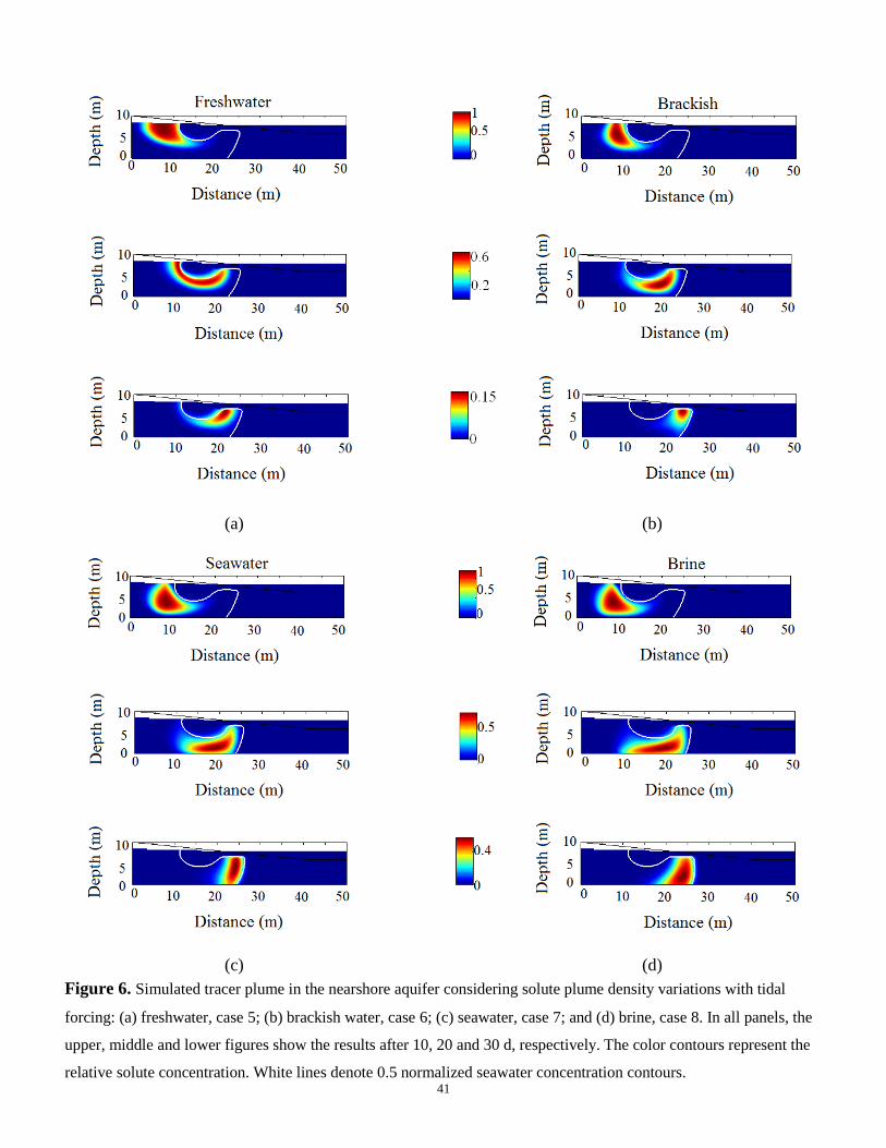
Figure 6 shows the simulated solute plume for cases 5-8, 10, 20 and 30 d after solute injection.
Due to the tide-induced seawater circulations (Fig. 5b) in the shallow intertidal region (the region of the
aquifer that is directly influenced by tidal fluctuations), tides alter the transport pathways for the solute
plumes (Fig. 6) compared with the case of no oceanic forcing (Fig. 3). This is particularly the case for
the less dense plumes that travel in the upper part of the aquifer. Compared with the cases with no
oceanic forcing, the plumes are transported downwards and around the tide-induced seawater
circulation cell and then discharge near the low tide mark (e.g., Figs. 3a and 6a), consistent with
[11,17,28,29]. For the denser plumes their transport pathways are more similar between the no oceanic
forcing and tidal cases, more so as the travel time increases. This is because the movement of the
plumes becomes strongly influenced by the upward flow associated with the saltwater wedge (e.g.,
Figs. 3c and 6c). As expected, as the density of the solute increases, the plume is transported deeper
into the aquifer with greater vertical and horizontal spreading evident (e.g., Fig. 6c,d).
The 0.5 normalized salt concentration contour lines (Fig. 6) show both the upper saline plume and
the lower saltwater wedge. Similar to the cases with no oceanic forcing, the position of the saltwater
wedge was affected by the solute plume: As the solute plume approached the wedge, the position of the
interface moved seaward according to the density contrast. Regardless of the plume density, the
position and size of the upper saline plume was not modified by the solute plume. This occurs because
the upper saline plume is formed due to advective flow driven by tidal forcing across the sloping beach
face whereas the saltwater wedge is formed due to density-driven seawater circulation. Therefore, the
density contrast associated with the solute plume does not alter the upper saline plume compared with
the saltwater wedge.

17
Figure 7 gives metrics used to characterize the solute plumes for the different cases with tidal
forcing. As expected, and similar to the cases with no oceanic forcing, the plume centroid sinks deeper
into the aquifer as the plume density increases (Fig. 7b). The position of the centroid is deeper than for
the no-forcing cases (1-4), again due to the shallow, tide-induced seawater circulation cell.
The temporal evolution of solute mass (Fig. 7a) follows a similar pattern for the four density cases
(fast solute discharge initially followed by a period of lower solute discharge across the interface). The
discharge rates decrease and the residence time (t80, Table 2) increases as the density of the plume
increases. Comparison with the no forcing cases (cases 1-4, Fig. 4a) shows that tidal forcing mostly
reduces the solute discharge flux from the aquifer to the sea. In all cases the aspect ratio (Fig. 7c)
decreases when the solute injection ends (after 6 d), i.e., the plume is elongated along the principal flow
direction. This is because the discharging freshwater is restricted to a narrow zone between the upper
saline plume and the saltwater wedge, which limits the transverse spreading of the plume. It also limits
the effect of the solute density contrast between cases 5-8 (that would lead to a more rounded shape
with an aspect ratio closer to unity). For the high-density solute plumes (cases 7 and 8), the longitudinal
rather than transverse stretching is increased due to the interaction of the plume with the bottom
(impermeable) boundary.
The shape and residence time of the plume are affected by the aquifer geometry including the
distance between the solute source and the bottom boundary. While the quantitative results presented
are specific to the setup used, the tide-induced oscillating flow in the aquifer increases the total
variance of the plumes by at least 50%; compare the maxima in Figs. 4d and 7d. Initially, the variance
increases with the plume density but, later, when the solute mass remaining in the aquifer is low, the
freshwater and brackish plumes have higher variance and thus are more spread. This indicates that
when most of the solute mass has been discharged and residual concentrations are relatively low,

18
denser solutes form a more compact plume. Denser solute plumes sink deeper into the aquifer and are
influenced less by tidally oscillating flows (which decrease with depth in the aquifer), resulting in less
plume dispersion. In the case of a degradable solute, this effect could influence its degradation as it
would undergo less mixing with the ambient groundwater and recirculating seawater prior to discharge.
3.3 Wave forcing
Phase-averaged normalized salt concentrations in a nearshore aquifer subject to high frequency sea
motion for case 12 (densest case: Brine) after 30 d is shown in Fig. 5c. The simulations show that wave
forcing induces local circulation cells under the beach face (15 < x < 22 m) (Fig. 5c, cf. [38,39]), which
can affect solute transport and submarine groundwater discharge because they modify the pore water
velocity (magnitude and direction) near the fresh/saltwater interface. The resulting salinity structure is
similar to the cases with tidal forcing, with a distinct upper saline plume in addition to the saltwater
wedge. The upper saline plume is formed by the saltwater infiltrating the beach face due to wave set-
up, uprush and backwash. These two saline zones are separated by the discharging fresh groundwater.
These results are consistent with those of [8]. A comparison of salt concentrations for tidal (Fig. 5b)
and wave forcing (Fig. 5c) shows that the width of upper plume in the tidal case is larger. The extent of
the upper saline plume depends on the specific wave and tidal forcing parameters adopted (e.g., A, ,
H, T) and, of course, the infiltration/exfiltration across the beachface.
Solute transport in the nearshore aquifer subject to wave forcing (cases 9-12) is shown in Fig. 8.
The solute distributions differ from those with tidal effects (Fig. 6). Figure 8 reveals that, similar to
tides, the wave-induced groundwater circulation modifies the discharge pathway. With waves present,
the solute plume first migrates seaward along the top of the aquifer, but as it approaches the wave-
induced flow circulation cell it is transported downwards. In the case of waves, however, the effects on
solute distribution in the nearshore aquifer are controlled mainly by the upper saline plume. Due to the

19
high frequency of waves (relative to tides), the flow oscillations are attenuated a short distance from the
beach face [37,48]. Tides instead have lower frequency and their signal penetrates further into the
saturated zone, and so have a different influence on the shape and travel time of the plume (e.g., [17]).
Similar to the no oceanic forcing and tidal cases, the results illustrate that dense solute plumes sink
deeper into the aquifer, and that the saltwater wedge is pushed further seaward as the plume density
increases. A comparison of Figs. 3, 5 and 8 shows that, in response to the solute plume, the seawater
wedge moved more for the waves or with no oceanic forcing cases and less for the cases with tidal
forcing. While the conditions of the oceanic forcing for these four cases (i.e., cases 9-12) were the same
(i.e., wave forcing), the positions of saltwater wedge were not.
Figure 9 shows the total mass, centroid, aspect ratio and total variance of the solute plume in the
nearshore aquifer subject to wave forcing and for different densities. The change in mass with time
reported in Fig. 9a shows that the average residence time is approximately 49 d, compared with 32 and
37 d for the no forcing and tidal cases, respectively (Table 2 and Fig. 9a). As for the tidal cases, the
plume centroids are affected by the density contrast and the shallow seawater circulation cell. That
means the trajectories of the centroids for the wave cases are deeper than for the cases with no oceanic
forcing. The aspect ratio plot (Fig. 9c) shows that the shapes of the solute plume with waves and tides
have similar features, i.e., the plume is stretched longitudinally. For cases 9-12, the maximum total
variances are similar, between 20 and 25 m2 and generally larger than variances for the tidal cases. The
largest spreading is obtained after 20-25 d, with a value that is larger than the corresponding result for
the cases with no oceanic forcing.

20
3.4 Combined wave and tidal forcing
Interactions between groundwater and combined oceanic forcing can affect the local
hydrodynamics, water exchange across the beach face and groundwater flow and solute transport. In
this section, we model plume movement in response to combined waves and tides using the phase-
averaged wave approach.
Phase-averaged normalized salt concentrations in a nearshore aquifer subject to combined wave
and tidal forcing for case 16 (densest case: Brine) and after 30 d are shown in Fig. 5d. The salinity
structure is qualitatively similar to the cases where waves and tides were considered separately. A
comparison of Figs. 5a-d shows that the largest upper saline plume occurs for the combined wave and
tide case (Fig. 5d), followed by the tidal (Fig. 5b) and wave cases (Fig. 5c). Although the size of the
plumes depends on the specific parameters used in the simulations (tidal amplitude and wave
frequency), the larger extent of the upper saline plume for the wave and tide case indicates that the
effect of the two forcing mechanisms is roughly additive.
The migration of the conservative solute plume in the beach aquifer for combined waves and tide
is illustrated in Fig. 10, while the plume’s spatial moments in the aquifer for cases 13-16 are shown in
Fig. 11. Results (both the patterns observed and the magnitude) are similar to those obtained for the
cases with tides only. However, the solute flow path is lengthened due to the added wave effects, which
produces a slightly larger saline plume beneath the beachface (cf. Figs. 6 and 8). For the freshwater
plume, the residence time is increased relative to the tide-only case, but is less than for the simulations
with waves only (Table 2). The brackish plume residence time is unchanged compared to that for tide
only. For the larger densities (seawater and brine), the residence time is controlled partially by the
plume reaching the impermeable bottom boundary, and is less than for the simulations with tide-only or
wave-only. The possible explanation for these different behaviors is that the larger upper saline plume

21
induces higher discharge rates for the denser cases (seawater and brine), whereas for the freshwater-
density case, the upper saline plume also increases the length of the solute flow path.
The 0.5 normalized salt concentration contour line (Fig. 10) shows both the upper saline plume
and the lower saltwater wedge. The mixing zone widens (10 < x < 23 m) compared with that for the
waves (15 < x < 22 m) and tide (12 < x < 21 m) considered separately (Fig. 8). In addition, due to the
effects of tide, the interface is pushed seaward compared with the wave-only cases. Similar to the cases
with waves and tidal forcing (Figs. 6 and 8), the position of the saltwater wedge is pushed seaward by
the denser solute plumes whereas the upper saline plume is not modified to any extent. For all cases
under oceanic forcing, the plume density affects the saltwater wedge location much more noticeably
than the upper saline plume (Figs. 6, 8 and 10).
4. Discussion
The simulations indicate that oceanic fluctuations increase the residence time and dispersion of
land-derived solute plumes in the coastal aquifer. This can be inferred from Figs. 4, 7, 9 and 11, panels
a (residence time) and d (plume spreading). In addition, Table 2 reports the normalized residual solute
mass in the aquifer at different times. Results are consistent with previous findings regarding the
influence of tides on solute transport and discharge from the aquifer to the sea (e.g., [17,29,31]). For
conditions where waves are the only oceanic forcing, the solute residence time is much larger than for
conditions with no forcing or tidal forcing only. For example, for the neutrally buoyant plume,
residence times are about 24, 26 and 44 d in the no-forcing, tide-only and wave-only cases,
respectively. With combined tides and waves, the residence time is similar to but slightly larger than
for the case with tides only (29 d). It is difficult to identify the reason for these differences, and in
particular for the large residence time observed for the wave-only case. A possible explanation is that
tidal forcing induces more significant mixing of the recirculating seawater in the upper saline plume

22
and the ambient discharging groundwater compared with waves, mainly because the wave-induced
oscillating flows are attenuated rapidly in the aquifer. In other words, the flow fluctuations induced by
waves cause much less displacement of the solute than the tidal oscillations [8]. In addition, waves are
non-symmetric around the SWL (tides both refill and drain the aquifer, while waves induce more
infiltration than exfiltration).
Concerning solute spreading, the total variance for the tide- and wave-only cases was similar, and
was about 50% larger than that for the no-forcing condition. More solute dispersion was observed for
combined waves and tides. The largest variance for this case was about twice that observed for the no-
forcing conditions. To examine further the effect of increased residence time, the solute discharge rates
across the beach face were computed (Fig. 12). Results are reported starting after the end of the
injection period, when some changes in solute mass can be observed (day 10 onwards). The general
trend is the same for all cases. Initially, while the plume migrates seawards the mass remains constant
(the discharge rate is zero). Once the solute plume reaches the beach face, the rate of discharge
increases (the normalized rate of change of solute mass in the aquifer, dm/dt, becomes more negative).
The shape of the discharge curve is bell-shaped and symmetric for the freshwater cases for all oceanic
forcing scenarios. The discharge curve becomes more skewed as the density of the solute plume
increases and it takes more time for the solute to leave the aquifer. This is due to the opposing effects
of density – which tends to maintain the solute near the impermeable lower boundary – and
groundwater flow, which moves the solute towards the beach face. The rate of discharge and residence
time for plumes of different densities shows consistent behavior, with most of the mass of the fresher
plumes being discharged earlier.
Oceanic forcing in combination with the density effects associated with land-derived solute
plumes significantly impact the flow circulations in the aquifer. Figure 5 reports the salt concentration

23
distribution, streamlines (white lines) and outline of the tracer plume (indicated by the 0.25C0 contour
line) 30 d after the end of the injection for the four different forcing conditions (phase-averaged flow
for the brine case is shown). In all situations, the tracer plume and seawater wedge form a single body
of denser water, which bends the streamlines and modifies the local flow direction. For the static and
tidal cases, a circulation cell is visible below the beach face. For the tides, however, the convective cell
is present. For the wave and combined tide-and-wave cases, the flow patterns are more complicated.
Several small circulation cells and convergence zones form due to the transient effect of waves. Results
for the combined tides and waves, obtained using the phase-averaged approach for waves, indicate that
the circulation cells observed in the presence of waves are persistent (although in reality they are
formed and destroyed during each wave cycle), and that their effect on the flow field is not negligible.
Our results have implications for the assessment and modeling of land-derived solute plumes. As
mentioned earlier, most research so far has considered only tidal effects. Our simulations indicate that,
along coastlines where oceanic waves have amplitudes similar to that of tides, neglecting the high
frequency component could still provide a reasonable estimate of the solute’s residence time in the
aquifer, whereas the spreading would be underestimated. Results indicate that wave fluctuations should
be considered in particular at locations where waves are the dominant forcing factor, i.e., along coasts
adjoining the Mediterranean, Baltic or Caribbean seas. At these locations, the tidal amplitude is often
small, in the range 0-10 cm [49]. For this condition, neglect of wave effects could lead to overestimates
the solute residence time and underestimates of plume spreading. In addition, the modeling results
indicate that waves drive a strong shallow circulation cell near the beach face, which is superimposed
on the similar tide-induced circulation [8]. This shallow circulation (due to tides only) was found to
enhance the degradation of organic solutes through increased oxygen availability in the shallow aquifer
[12] and also increase nutrient turnover rates, which promotes biogeochemical processes in the
intertidal zone (e.g., [50]). Due to the greater circulation observed in the combined wave-tide

24
simulations, it is expected that waves will increase further the oxygen availability in the shallow beach
sediments. For situations dominated by wave forcing, increased oxygen availability in parallel to the
residence time increase could have a beneficial effect on the natural attenuation of, for example,
biodegradable organic solutes prior to their discharge to the sea.
It should, nevertheless, be noted that while this study advances modeling of solute transport in the
nearshore aquifer, the results could be affected by the simplifying assumptions required to reduce the
computational burden. In particular, unconfined aquifers fill and drain in response to oceanic
fluctuations, and seepage faces can form [8,27,51,52]. Vadose zone flow and the seepage face are,
however, not modeled in SEAWAT [52]. This is especially true in the case of high-frequency
fluctuations (waves), because the wave period is similar or smaller than the time required by a single
finite-difference cell in MODFLOW to saturate and drain. Boufadel et al. [30], however, observed that
neglecting seepage face formation has a limited effect on solute transport predictions in aquifers
subjected to tides, and while neglecting unsaturated flow can affect predictions for fine-grained sandy
beaches, predictions are less influenced for medium- to coarse-grained beaches. The simulations
conducted in this study were for a medium-grained sandy nearshore aquifer and so unsaturated flow
and seepage face formation are considered to have only minor effects on the results.
5. Conclusions
The influence of wave and tidal forcing on solute transport in the nearshore aquifer was
investigated via a comprehensive numerical investigation. Our investigation showed that:
• The results confirmed previous investigations that in nearshore aquifers subject to tidal or wave
forcing, there is an upper saline plume below the beach face in addition to the classical saltwater
wedge within the aquifer. Only the latter exists for non-oceanic forcing conditions;

25
• The upper saline plume is largest for the combined wave-and-tide case followed by the tidal and
wave cases. The extent of the upper saline plume depends on the specific wave and tidal forcing
parameters;
• A flow circulation cell below the beach and just seaward of the seawater wedge/freshwater divide
was observed for the static and tidal cases. This is primarily driven by density differences. For the
cases with waves and combined tides and waves, the flow field is complex with numerous small
circulation cells beneath the beach face;
• Variable density solute plumes entering the coastal aquifer modify the groundwater flow field.
When the plume is far from the salt-freshwater interface, the streamlines are distorted and exit the
aquifer near or above the SWL. As the solute plume approaches the seawater wedge, they merge and
modify local flow patterns until the solute plume is removed;
• The density contrast associated with the solute plume has less effect on the upper saline plume than
the saltwater wedge location;
• The solute plume density has a significant effect on the specific transport pathway and spreading of
a solute plume in the aquifer. Plume spreading increased with density;
• While the solute residence time increased with increasing solute plume density in the absence of
oceanic forcing, tides modulate the solute density effects. Solute plume transport around the upper
saline plume – which occurs for all tidal cases – reduces solute density effects and decreases the
solute discharge rate;
• Oceanic fluctuations increase the residence time and dispersion of land-derived solute plumes within
the aquifer. For cases where waves are the only oceanic forcing, the residence time increase is much
larger than for tide-only cases;
26
• The shape of the solute plume discharge curve across the beach face is bell-shaped and symmetric
when the plume density is the same as the freshwater density, and becomes more skewed as the
solute plume density increases. This is because of longer (and slower) solute transport paths to the
beach face as the denser plumes move deeper into the aquifer;
• Where oceanic waves have small amplitude compared to tides, solute transport is only weakly
affected by waves, which can be neglected. Similarly, where waves are the dominant forcing, tidal
effects can be neglected. However, in general, as the effects of tides and waves induce the formation
of an upper saline plume beneath the beach face and are additive, both combined wave and tidal
effects should to be accounted for.
• Although the simulations considered conservative solutes only, the findings regarding the residence
time and the extent of mixing between the ambient groundwater and solute plume are relevant to
predictions of degradation rates (e.g., larger residence time corresponds to potentially greater
degradation of the solute in the aquifer prior to discharge).
Acknowledgement
Support of the Swiss National Foundation (SNF 200021-135322) is acknowledged.
Appendix. Spatial moments and covariance tensor
The low-order moments are defined as follows:
0 , , ,M t C x z t dxdz (A-1)
1χ
0
, , χ,
C x z t dxdzM t
M
(A-2)

27
1 1
11
0
, ,,
x zC x z t x M z M dxdzM t
M
(A-3)
2
1χ
2χ
0
, , χ,
C x z t M dxdzM t
M
(A-4)
2 11
11 2
,x
z
M Mt
M M
σ (A-5)
where M0 is the zero-order moment, χ = x or z, M1χ are the first-order moments, M2χ are the second-
order moments, and M11 and σ are the covariance and covariance tensor, respectively. The principle
axes of the plume are given by the eigenvectors of σ, while the aspect ratio is given by the
transverse/longitudinal ratio of its eigenvalues. The plume centroid is given by (M1x, M1z).
References
[1] St. Germain DJ, Cohen DK, Frederick JJ. A retrospective look at the water resource management policies in Nassau
County, Long Island. J Amer Water Resour Assoc 2008;44:1337–46.
[2] Werner AD, Bakker M, Post VE, Vandenbohede A, Lu C, Ataie-Ashtiani B, Simmons CT, Barry DA. Seawater
intrusion processes, investigation and management: Recent advances and future challenges. Adv Water Resour 2012.
In press, doi: 10.1016/j.advwatres.2012.03.004.
[3] Cox ME, Hillier J, Foster L, Ellis R. Effects of a rapidly urbanising environment on groundwater, Brisbane, Queensland,
Australia. Hydrogeol J 1996;4:30–47.
[4] Li L, Barry DA, Jeng D-S, Prommer H. Tidal dynamics of groundwater flow and contaminant transport in coastal
aquifers. In Coastal Aquifer Management—Monitoring, Modeling, and Case Studies, Edited by A.H.-D. Cheng and D.
Ouazar, chap. 6, pp. 115–141, 2004, Lewis, Boca Raton, Florida, USA.
[5] Grassi S, Cortecci G, Squarci P. Groundwater resource degradation in coastal plains: The example of the Cecina area
(Tuscany–Central Italy). Appl Geochem 2007;22:2273–89.

28
[6] Boufadel MC, Siudan MT, Venosa AD. Tracer studies in laboratory beach simulating tidal influences. ASCE J Env Eng
2006;132:616–23.
[7] Bakhtyar R, Barry DA, Li L, Jeng D-S, Yeganeh-Bakhtiary A. Modeling sediment transport in the swash zone: A
review. Ocean Eng 2009a;36:767–83.
[8] Xin P, Robinson C, Li L, Barry DA, Bakhtyar R. Effects of wave forcing on a subterranean estuary. Water Resour Res
2010;46:W12505, doi:10.1029/2010WR009632.
[9] Robinson MA, Gallagher D, Reay W. Field observations of tidal and seasonal variations in groundwater discharge to
tidal estuarine surface water. Ground Water Monit Remed 1998;18:83–92.
[10] Robinson C, Gibbes B, Li L . Driving mechanisms for groundwater flow and salt transport in a subterranean estuary.
Geophys Res Lett 2006;33:L03402, doi: 10.1029/2005GL025247.
[11] Robinson C, Li L, Barry DA. Effect of tidal forcing on a subterranean estuary. Adv Water Resour 2007;30:851–65.
[12] Robinson C, Brovelli A, Barry DA, Li L. Tidal influence on BTEX biodegradation in sandy coastal aquifers. Adv
Water Resour 2009;32:16–28.
[13] Boufadel MC. A mechanistic study of nonlinear solute transport in a groundwater-surface water system under steady
state and transient hydraulic conditions. Water Resour Res 2000;36:2549–65.
[14] Destouni G, Prieto C. On the possibility for generic modelling of submarine groundwater discharge. Biogeochemistry
2003;66:171–86.
[15] Mango AJ, Schmeeckle MW, Furbish DJ. Tidally induced groundwater circulation in an unconfined coastal aquifer
modeled with a Hele-Shaw cell. Geology 2004;32:233–6.
[16] Kacimov A, Abdalla O. Water table response to a tidal agitation in a coastal aquifer: The Meyer-Polubarinova-Kochina
theory revisited. J Hydrol 2010;392:96–104.
[17] Brovelli A, Mao X, Barry DA. Numerical modeling of tidal influence on density-dependent contaminant transport.
Water Resour Res 2007;43:W10426, doi:10.1029/2006WR005173.

29
[18] Licata IL, Langevin CD, Dausman AM, Alberti L. Effect of tidal fluctuations on transient dispersion of simulated
contaminant concentrations in coastal aquifers. Hydrogeol J 2011;19:1313–22.
[19] Ataie-Ashtiani B, Volker RE, Lockington DA. Tidal effects on sea water intrusion in unconfined aquifers. J Hydrol
1999;216:17–31.
[20] Mao X, Enot P, Barry DA, Li L, Binley A, Jeng D-S,. Tidal influence on behaviour of a coastal aquifer adjacent to a
low-relief estuary. J Hydrol 2006;327:110–27.
[21] Kuan WK, Jin G, Xin P, Robinson C, Gibbes B, Li L. Tidal influence on seawater intrusion in unconfined coastal
aquifers. Water Resour Res 2012;48:W02502, doi:10.1029/2011WR010678.
[22] Guo Q, Li H, Boufadel MC, Sharifi Y. Hydrodynamics in a gravel beach and its impact on the Exxon Valdez oil spill. J
Geophys Res Oceans 2010;115:C12077, doi: 10.1029/2010JC006169.
[23] Mao X, Prommer H, Barry DA, Langevin CD, Panteleit B, Li L. Three-dimensional model for multi-component
reactive transport with variable density groundwater flow. Env Model Softw 2006b;21:615–28.
[24] Werner AD, Lockington D A. Tidal impacts on riparian salinities near estuaries, J Hydrol 2006;328:511–22.
[25] Guo Q, Li H, Boufadel MC, Sharifi Y. Hydrodynamics in a gravel beach and its impact on the Exxon Valdez oil spill. J
Geophys Res Oceans 2010;115:C12077, doi: 10.1029/2010JC006169.
[26] Li H, Boufadel MC. Long-term persistence of oil from the Exxon Valdez spill in two-layer beaches. Nature Geosci
2010;3:96–9.
[27] Xia Y, Li H, Boufadel MC, Sharifi Y. Hydrodynamic factors affecting the persistence of the Exxon Valdez oil in a
shallow bedrock beach. Water Resour Res 2010;46:W10528, doi:10.1029/2010WR009179.
[28] Zhang Q, Volker RE, Lockington DA. Influence of seaward boundary condition on contaminant transport in
unconfined coastal aquifers. J Contam Hydrol 2001;49:201–15.
[29] Zhang Q, Volker RE, Lockington DA. Experimental investigation of contaminant transport in coastal groundwater.
Adv Env Res 2002;6:229–37.

30
[30] Boufadel MC, Xia Y, Li H. Modeling solute transport and transient seepage in a laboratory beach under tidal influence.
Env Model Softw 2011;26:899–912.
[31] Elfeki AMM, Uffink GJM, Lebreton S. Simulation of solute transport under oscillating groundwater flow in
homogeneous aquifers. J Hydraul Res 2007;45:254–60.
[32] Massel SR. Circulation of groundwater due to wave set-up on a permeable beach. Oceanologia 2001;43:279–90.
[33] Jeng D-S, Barry DA, Li L. Water wave-driven seepage in marine sediments. Adv Water Resour 2001;24:1–10.
[34] Voss CI, Provost AM. SUTRA, a model for saturated-unsaturated, variable-density groundwater flow with solute or
energy transport. U.S. Geological Survey. Water-Resources Investigations Report, 02-4231, 2002, 250 p., Reston,
Virginia, USA. http://water.usgs.gov/nrp/gwsoftware/sutra_2.0/SUTRA_2D3D_1-documentation.pdf, last accessed 13
November 2012.
[35] Li L, Barry DA, Pattiaratchi CB, Masselink G. BeachWin: Modeling groundwater effects on swash sediment transport
and beach profile changes. Env Model Softw 2002;17:313–20.
[36] Boehm AB, Shellenbarger GG, Paytan A. Groundwater discharge: Potential association with fecal indicator bacteria in
the surf zone. Env Sci Technol 2004;38:3558–66.
[37] Bakhtyar R, Ghaheri A, Yeganeh-Bakhtiary A, Barry DA. Process-based model for nearshore hydrodynamics,
sediment transport and morphological evolution in the surf and swash zones. Appl Ocean Res 2009b;31:44–56.
[38] Bakhtyar R, Brovelli A, Barry DA, Li L. Wave-induced watertable fluctuations, sediment transport and beach profile
change: Modeling and comparison with large-scale laboratory experiments. Coast Eng 2011;58:103–18.
[39] Bakhtyar R, Barry DA, Brovelli A. Numerical experiments on interactions between wave motion and variable-density
coastal aquifers. Coast Eng 2012;60:95–108.
[40] Langevin CD, Thorne DT Jr, Dausman AM, Sukop MC, Weixing G. SEAWAT Version 4: A computer program for
simulation of multi-species solute and heat transport. U.S. Geological Survey Techniques and Methods Book 6,
Chapter A22, 2008, 39 p., http://pubs.usgs.gov/tm/tm6a22/, last accessed 13 November 2012.

31
[41] Harbaugh AW, Banta ER, Hill MC, McDonald MG. MODFLOW-2000, The US Geological Survey modular ground-
water model-User guide to modularization concepts and the groundwater flow process. U.S. Geological Survey, Open
File Report 00–92, 2000. http://water.usgs.gov/nrp/gwsoftware/modflow2000/modflow2000.html, last accessed 13
November 2012
[42] Zheng C, Wang PP. MT3DMS: A modular three-dimensional multispecies transport model for simulation of advection,
dispersion, and chemical reactions of contaminants in groundwater systems; documentation and user’s guide. Contract
Rep. SERDP-99-1, U.S. Army Engineering Research Development Center, Vicksburg, Mississippi, 1999, USA, 169
p., http://hydro.geo.ua.edu/mt3d/index.htm, last accessed 13 November 2012.
[43] Bakhtyar R, Barry DA, Yeganeh-Bakhtiary A, Ghaheri A. Numerical simulation of surf-swash zone motions and
turbulent flow. Adv Water Resour 2009c;32:250–63.
[44] Bakhtyar R, Barry DA, Yeganeh-Bakhtiary A, Ghaheri A, Li L, Parlange J-Y, Sander GC. Numerical simulation of
two-phase flow for sediment transport in the inner-surf and swash zones. Adv Water Resour 2010;33:277–90.
[45] Bakhtyar R, Barry DA, Kees CE. Numerical experiments of breaking waves on contrasting beaches using a two-phase
flow method. Adv Water Resour 2012;48:68–78.
[46] Longuet-Higgins MS. Wave set-up, percolation and undertow in the surf zone. Proc R Soc A 1983;390:283–91.
[47] Barry DA, Sposito G. Three-dimensional statistical moment analysis of the Stanford/Waterloo Borden tracer data.
Water Resour Res 1990;26:1735–45.
[48] Nielsen P. Tidal dynamics of the watertable in beaches. Water Resour Res 1990;26:2127–34.
[49] Lyard F, Lefevre F, Letellier T, Francis O. Modelling the global ocean tides: Modern insights from FES2004. Ocean
Dyn 2006;56:394–415.
[50] Anschutz P, Smith T, Mouret A, Deborde J, Bujan S, Poirier D, Lecroart P. Tidal sands as biogeochemical
reactors. Estuar Coast Shelf Sci 2009;84:84–90.
[51] Li L, Barry DA, Pattiaratchi CB. Numerical modelling of tide-induced beach water table fluctuations. Coastal Eng
1997;30:105–23.

32
[52] Post VEA. A new package for simulating periodic boundary conditions in MODFLOW and SEAWAT. Comput Geosci
2011;37:1–7.
[53] Zheng C, Bennett GD. Applied Contaminant Transport Modeling, second ed. Wiley, 2002, New York, USA.
[54] Diersch H-JG, Kolditz O. Variable-density flow and transport in porous media: Approaches and challenges. Adv Water
Resour 2002;25:899–944.

33
Tables
Table 1. Characteristics of the numerical experiments.
Case Oceanic condition H (m) A (m) ω (rad d-1
) T (s) ρP
(g l-1
) Solute
1 static sea level - - - - 998.2 freshwater
2 static sea level - - - - 1012.5 brackish
3 static sea level - - - - 1025.0 seawater
4 static sea level - - - - 1037.5 brine
5 tide - 0.5 12.57 - 998.2 freshwater
6 tide - 0.5 12.57 - 1012.5 brackish
7 tide - 0.5 12.57 - 1025.0 seawater
8 tide - 0.5 12.57 - 1037.5 brine
9 wave 0.5 - - 7 998.2 freshwater
10 wave 0.5 - - 7 1012.5 brackish
11 wave 0.5 - - 7 1025.0 seawater
12 wave 0.5 - - 7 1037.5 brine
13 wave + tide 0.5 0.5 12.57 7 998.2 freshwater
14 wave + tide 0.5 0.5 12.57 7 1012.5 brackish
15 wave + tide 0.5 0.5 12.57 7 1025.0 seawater
16 wave + tide 0.5 0.5 12.57 7 1037.5 brine

34
Table 2. Normalized residual solute mass as a function of time and the period of time when 80% of the mass has been removed.
Elapsed
time (d)
No oceanic oscillations Tide Wave Combined wave and tide
freshwater brackish seawater brine freshwater brackish seawater brine freshwater brackish seawater brine freshwater brackish seawater brine
20 0.523 0.636 0.770 0.828 0.624 0.723 0.799 0.833 0.921 0.993 0.997 1 0.763 0.753 0.833 0.817
40 2 × 10⁻⁴ 0.001 0.081 0.292 0.003 0.011 0.123 0.314 0.423 0.240 0.396 0.520 0.015 0.016 0.105 0.216
60 2 × 10⁻⁶ 8 × 10⁻⁵ 0.008 0.112 10-4 0.001 0.018 0.12 0.011 0.008 0.058 0.221 10-4 0.001 0.012 0.058
80 9 × 10⁻⁷ 3 × 10⁻⁵ 0.002 0.030 3 × 10⁻⁵ 4 × 10⁻⁴ 0.005 0.042 2 × 10⁻⁴ 0.001 0.013 0.098 3 × 10⁻⁵ 2 × 10⁻⁴ 0.003 0.016
100 4 × 10⁻⁷ 10-5 0.001 0.009 10-5 10-4 0.002 0.017 9 × 10⁻⁵ 8 × 10⁻⁵ 0.005 0.034 10-5 10-4 0.001 0.006
120 0.007 0.012
t80 (d) *
24 25 34 48 26 29 45 49 44 42 48 63 29 29 35 41
*t80 represents the time when 80% of the mass has been removed (residence time).

35
Figures
Figure 1. Schematic of the numerical model setup (after [39]). The aquifer was unconfined,
homogeneous and isotropic with a hydraulic conductivity of 15 m d-1
. The sand porosity was 0.4 with
longitudinal and transversal dispersivity of 0.2 and 0.02 m, respectively [53]. The freshwater and
saltwater densities were 998.2 and 1.025 × 10³ kg m
-3, respectively. A non-reactive solute was
introduced as a line source placed at the watertable at 2.8 < x < 3.8 m from the freshwater boundary
(16.2-17.3 m from the shoreline). The tracer injection rate was 0.375 m3
d-1
and lasted 6 d. The double-
ended arrow on the right represents the oceanic fluctuations where H is the wave height and A is the
tidal amplitude. The tidal amplitude was 0.5 m with a semi-diurnal period of 0.5 d. Waves with a height
of 0.5 m and a period of 7 s were used to simulate wave forcing (Table 1). A grid spacing of 0.2 m
(both directions) was used in all simulations to meet stability constraints (Péclet number < 2, [54]). The
time step was selected automatically to keep the Courant number smaller than 0.75.
Saltwater
wedge
50 m
10 m
Impermeable
bed
Beach face Wave or tide motion in
the nearshore
SWL
Watertable
elevation 10
1 d = 2 m
Seawater
depth
16.2 m
6 m
4 m
Constant
head
Sea-level
oscillation
(H or A)
Solute source
(x,z) = (0,0)

36
(a)
(b)
(c)
(d)
Figure 2. Normalized salt concentration, streamlines (in white) and 0.25C0 contour line for the tracer
plume (dashed line in magenta) in the aquifer a static sea at different times (5,10,20 and 30 d,
respectively). Results are for densest case (Brine, case 4).
SWL
SWL
SWL
SWL

37
(a) (b)
(c) (d)
Figure 3. Simulated tracer plume in the nearshore aquifer considering solute plume density variations without
oceanic forcing: (a) freshwater, case 1; (b) brackish water, case 2; (c) seawater, case 3; and (d) brine, case 4. In all
panels, the upper, middle and lower figures show the results after 10, 20 and 30 d, respectively. The color contours
represent the relative solute concentration. White lines denote 0.5 normalized seawater concentration contours.

38
(a) (b)
(c) (d)
Figure 4. Spatial moments of the solute plume in the nearshore aquifer without oceanic forcing and for
different densities (cases 1-4, Fig. 3): (a) zeroth moment (total mass), horizontal dashes shows t80; (b)
evolution of first spatial moment (centroid); (c) aspect ratio; and (d) total plume variance.

39
(a)
(b)
Circulation zone below the beach face Upper saline plume
SWL
SWL
HT
LT

40
(c)
(d)
Figure 5. Normalized salt concentration, simulated streamlines (in white) and 0.25C0 tracer plume (dashed line,
magenta) in the aquifer for different sea-level oscillations: (a) static sea level, case 4; (b) tide, case 8; (c) wave, case
12; (d) combined wave and tide, case 16. All panels show phase-averaged results, after 30 d and for densest case
(brine).
Circulation zone near the surface Convergence zone
Wave setup + HT
Wave setup + LT
SWL Wave setup
41
(a) (b)
(c) (d)
Figure 6. Simulated tracer plume in the nearshore aquifer considering solute plume density variations with tidal
forcing: (a) freshwater, case 5; (b) brackish water, case 6; (c) seawater, case 7; and (d) brine, case 8. In all panels, the
upper, middle and lower figures show the results after 10, 20 and 30 d, respectively. The color contours represent the
relative solute concentration. White lines denote 0.5 normalized seawater concentration contours.

42
(a) (b)
(c) (d)
Figure 7. Simulated spatial moments of the solute plume in the nearshore aquifer under tidal forcing
and for different densities (cases 5-8, Fig. 6): (a) zeroth moment (total mass), horizontal dash-line
shows t80; (b) evolution of first spatial moment (centroid); (c) aspect ratio; and (d) total plume variance.

43
(a) (b)
(c) (d) Figure 8. Simulated tracer plume in the nearshore aquifer considering solute plume density variations with wave forcing:
(a) freshwater, case 9; (b) brackish water, case 10; (c) seawater, case 11; and (d) brine, case 12. In all panels, the upper,
middle and lower figures show the results after 10, 20 and 30 d, respectively. The color contours represent the relative
solute concentration. White lines denote 0.5 normalized seawater concentration contours.

44
(a) (b)
(c) (d)
Figure 9. Simulated spatial moments of the solute plume in the nearshore aquifer under waves (cases
9-12, Fig. 8): (a) zeroth moment (total mass), horizontal dash-line shows t80; (b) evolution of first
spatial moment (centroid); (c) aspect ratio; and (d) total plume variance.

45
(a) (b)
(c) (d)
Figure 10. Simulated tracer plume in the nearshore aquifer considering solute plume density variations under
combined wave and tide: (a) freshwater, case 13; (b) brackish water, case 14; (c) seawater, case 15; and (d) brine,
case 16. In all panels, the upper, middle and lower figures show the results after 10, 20 and 30 d, respectively. The
color contours represent the relative solute concentration. White lines denote 0.5 normalized seawater
concentration contours.

46
(a) (b)
(c) (d)
Figure 11. Simulated spatial moments of the solute plume in the nearshore aquifer under combined
wave and tide forcing (cases 13-16, Fig. 10): (a) zeroth moment (total mass), horizontal dash-line
shows t80; (b) evolution of first spatial moment (centroid); (c) aspect ratio; and (d) total plume variance.

47
(a) (b)
(c) (d)
Figure 12. Solute discharge rate across the beach face: (a) no oceanic forcing; (b) tide; (c) wave; and (d) combined wave and tide, where
vertical axis is the rate of change of the mass (normalized by the initial mass) of solute in the aquifer over time).