Embed Size (px)
Citation preview

Wireless Personal Communications 30: 131–152, 2004.C© 2004 Kluwer Academic Publishers. Printed in the Netherlands.
Transparent Antenna Solutions for Adaptive Coverage Systems
PATRICK C.F. EGGERS and BEN KRØYERCenter for Person Kommunikation, Aalborg University, Niels Jernes Vej 12, DK9220 Aalborg, DenmarkE-mail: [email protected], [email protected]
Abstract. Roll out of 3G or expansion of maturing 2G, 2 12 G networks – could promote implementation of more
flexible infra structure solutions, as resource limitations can make further development or ad-hoc expansion difficult,with the currently used traditional fixed sector base stations. Vendor transparency and possible system transparencyis a current feature of most roof installations in 2G and 2 1
2 G networks, i.e. the antenna system can be acquiredindependently from base station equipment vendors. This paper describes Adaptive Coverage System (ACS)solutions that maintain similar vendor and system transparency, so no extra supplier constraints are put on possibleinstallation of an ACS in current and future networks.
Keywords: Adaptive, coverage, antennas, cellular
1. Introduction
Exploitation of traffic location knowledge is relevant with respect to the ability to relocateresources in the spatial domain and thus possibly reduce needs or base station (BS) sites. Theexecution of this relocation can be performed via an Adaptive Coverage System (ACS) asdescribed in this paper. The potential savings in resources are sheer equipment and installationcost, if reduced number of BS can result – but foremost the reduced need in expanding roofaccess for new sites (which by it own is cost saving due to less need for acquisition of accessrights). Roof access seems to become one of the most crucial and hard to come by resources –particular at times where public concern is raised towards possible health issue with respect toemitted radio power from 3G BS masts. Depending on operation strategy, utilisation of ACSin the network can reduce the daily exposure of ‘broad cast’ sector power and could thus alsobe an element in the radio power versus health debate.
The EU IST project Cellular Network Optimisation Based on Mobile Location (CELLO)[1] has developed transparent antenna modules for ACS topologies that were tested duringthe project. This paper describes the concept and implements of these ACS antenna solutions,while an accompanying paper [2] in this special issue describes the obtained performance inmore detail.
The ACS concept in the CELLO project was the basic idea of exploiting localisation-information for adjusting the antenna patterns to achieve an increased network capacity andstability.
A smart antenna system combines multiple antenna elements with a signal-processingcapability to optimise its radiation and/or reception pattern automatically in response to thesignal environment [3–7]. Although such adaptive or smart antennas have been widely in focusthe last few years, simpler more general antenna system manipulation approaches have hadless attention. Base station antennas have until now been omni directional or sectored. This

132 P.C.F. Eggers and B. Krøyer
can be regarded as a ‘waste’ of power as most of it will be radiated in other directions thantowards the user. In addition, other users will experience the power radiated in other directionsas interference. The idea of smart antennas is to use base station antenna patterns that are notfixed, but adapt to the current radio conditions. This can be visualised as the antenna directinga beam toward the communication partner only. On a coarser scale, adaptive coverage tries tooptimise average coverage and thus signal quality for groups of users covering a certain area.Consequently its potential for interference suppression is also only on the average scale.
The CELLO project was aimed towards testing feasibility of antenna systems that canprovide adaptivity in the general picture (i.e. capacity wise) while still being simple enoughto financially and technically allow wide application in existing and next generation cellularnetworks.
So it is important here to distinguish between:
– Adaptive coverage (CELLO objective): Not individual user ‘tracking’/switching but ‘enmasse’ manipulation through change in sector coverage. I.e. user Quality of Service (QoS)improvement is achieved via better access, reduced dropped call rate, etc., which also spinsoff in average interference suppression and thus live link quality
versus
– Adaptive/Smart antennas: Normally understood to be operating on individual user links andthus having potential for link quality improvement via individual ‘diversity action’
The adaptive coverage manipulation in CELLO was teamed with localisation of traffic hotspots, so that free capacity can be redirected to cover more distressed areas. The time frameof change in adaptive coverage is in the order of 10 s of minutes or hours, where adaptiveantenna systems operate on symbol or frame basis. Thus adaptive coverage is not attemptingto combat short term or shadow fading/interference, but rather to adjust to changes in trafficduring the day (i.e. rush hours, special mass events, etc.).
The ACS antenna role in the CELLO project has been the necessary hardware implementa-tion to facilitate simple tests of adaptive coverage manipulation principles. In its own right, theACS solutions have implemented different hardware design strategies as well as they spurreddevelopment of a flexible modular antenna array (MAA).
The ACS concept relies on adapting coverage according to traffic needs via correspondingchanges in BS antenna patterns. This should allow eased rolled out of new networks and ofexpansion of matured networks, by
A. Flexibility regarding roof access – as extended capacity via coverage manipulations mightbe achieved with existing BS sites or only reduced number of extra sites. The minimisationof needed roof access also implies keeping same or less roof occupancy as experiencedwith space diversity systems, by replacing them by polarisation diversity implementations.Roof access is not only a matter of identifying potential sites – which involves much morethan just optimising BS placement based on radio and network parameters. It is just asmuch a legal issue regarding town planning constraints and even public health issue debatesand politics, etc.
B. Possibility of high degree of automatic tuning of networks – thus the potential for less-ened initial planning requirements and delay till installation. We introduce the term ‘Slackplanning’ for this strategy. 2G and 2 1
2 G network have a strong planning stage with respectto optimum cell lay layout given the topography, build up, town-planning constraints and

Transparent Antenna Solutions for Adaptive Coverage Systems 133
demographics/user wishes. Propagation models are used to identify the best possible fixedcoverage BS sites. After initial installation, operators mostly perform test measurements toensure coverage (indoor coverage is still an issue), monitor competitors (both for interfer-ence issues and degree of coverage and service quality offered by others). Slack planningrelies on the ACS capability to adjust coverage directly from network control without hav-ing a mast technician on the roof doing any hardware modifications. Thus, coverage finetuning can be effectuated much faster and may even converge faster and more accuratelywhen based directly on network feedback from terminal reports (i.e. actual coverage whenlinked with localisation information) – instead of initial hard planning using propagationand traffic models for prediction.
C. Possible savings in infrastructure equipment for the same coverage – as for exampleallowing free capacity to be moved toward hot spots. Thus, the possibility of designingthe network with less over-head for peak hour loads. I.e. the potentially reduced numberof fill-in cells and new BS installations to cover dense traffic spots. Futher savings appeardue to reduced need for acquiring access rights to new sites.
Although initially the last point was an interesting motivator from network operator pointof view – now the first point has taken over focus. Specially taking into account recent publicconcern of 3G masts and possible health issues with respect to the radiated power – causingtown halls and building owners to ban1 installation of new BS sites on their premises.
2. The CELLO ACS Concept
A transparent implementation of the ACS will allow similar applicability as for the currentlyused fixed sector antenna systems in mobile networks, i.e. no vendor (or system) ties betweenBS transceiver supplier and roof equipment. This is in contrast to commercial solutions [8–10]relying on non-standard proprietary integration of BS equipment and antenna system, thusforcing network operators to exchange existing BS equipment if applying adaptive antennasystems.
Thus, a transparent implementation implies that pattern manipulation needs to be performedat RF with straight forward interfacing to existing transceivers [11]. I.e. a simple replacementof a traditional antenna system with an ACS antenna module should be possible at the cableend on the roof. Any hardware state changes needed in the pattern control of ACS antennasshould be part of the antenna module. Such hardware control is performed via a control box(also called switch box) that includes the necessary elements (switches etc.) for RF changesin the feed of the antenna elements. The control box together with the ACS antennas shouldconstitute a nearly autonomous unit with respect to servicing and network coverage tuning –reducing further needs for roof technician intervention after installation.
In the CELLO project two approaches for the Adaptive Coverage System were considered.A simple approach was used for the CELLO trial while a more advanced approach wastargeted for later operational use. The low-complex approach could be based on either of twotechniques.
1 Situation by mid November 2003 in Denmark – slowing down 3G roll out. Expected that similar conditionsare experienced in other European countries – as the reports leading the public focus on possible health influencefrom radio power of 3G masts, have been internationally available.

134 P.C.F. Eggers and B. Krøyer
Table 1. Different design assumption for the two CELLO ACS implementations
Approach Switched Integrated
1. ACS goal Simple and predictable ‘Autonomous’
Dedicated to specific sites General/flexible
2. Antenna elements Available Array/mechanical
Commercial elements Custom design
3. Switch control PC control 2(3) state Adaptive
4. Application Deterministic location of hotspots Random location of hotspots
5. Network control Pre-programmed or manual action Automatic MGIS
– Mechanically steered elements (so the control box would be a driver box for the step motorsinvolved)
– Switched elements (pointed at selected directions by a simple switching between fixedbeams)
The implementation should be a rather straightforward design and based on commerciallyavailable antenna elements. In the early phase of CELLO, it was decided to adopt the switchedantenna solution, as it is the simplest and can be realised by readily available components. Theadvanced solution could be an antenna based on electrical beam synthesis. In the following theapproaches are referred as ‘switched antenna solution’ and ‘integrated antenna solution’ (orflexible antenna solution, also known as modular antenna array (MAA) [12]). This structureof the ACS and its impact in the CELLO project is summarised in Table 1.
The switched approach is suitable for fairly predictable reoccurring traffic change patterns(rush hours versus off hours), while the integrated MAA solution potentially allows for on thefly adaptation to unforeseen events, controlled via a Mobile Geographical Information System(MGIS). The switch approach can be ‘hard coded’ via fixed timing schedules – or rely ontraffic data feedback in the network to identify the proper time of switching the coverage states.The integrated MAA solution normally would be controlled solely based on traffic feedback(intensity and location, i.e. hot spot identification) via the MGIS, to utilise the potential outmost.
The switched ACS is controlled by a control network shown in Figure 1. The MGIScontains the information about required coverage areas and the corresponding switch settingsat different times. The switch settings are sent to the antenna module via a control PC.
The PC to Switch box interface is the control (micro command) line, while the switchbox toantenna interface is the actualisation line; (i.e. logic that interprets the control line commandsand then supplies the switches with needed voltage/current). The antenna control operation isdescribed more in detail in the next section.
2.1. RADIO AND HARDWARE REQUIREMENTS FOR THE CELLOGSM1800 TRIALS
For a vendor transparent solution, the ACS should have mechanical and mounting requirementssimilar to existing antenna systems. An important part is the radio interface between basestation transceivers and the ACS roof module, the control box in between antenna elementsand transceivers. Thus, the control box connector types and properties need to be the same as

Transparent Antenna Solutions for Adaptive Coverage Systems 135
Figure 1. ACS interfacing diagram with ACS Antenna Tool (AAT), Antenna Driver Component (ADC) and switchcontrol (SWC).
for the existing fixed sector antenna elements, to allow a simple exchange of antenna systemsusing existing RF cables to the transceivers.
One important parameter of the antenna is the horizontal 3 dB beam width. A horizontal3 dB beam width of 65◦ was normally used in ELISA’s network and at the CELLO trial sites(and the elements should provide polarisation diversity, see Section 2.4). The network hadfew base stations with antenna element beam widths of 33◦ and 85◦. For simplest ‘switched’solution, commercially available antennas were picked from the ELISA supplier catalogues.Here a 33◦ coverage element was used in the focus state of the focussing test and the extendedrange state in the range extension test. Thus, the only extra work for the roof technician withrespect to existing roof installations, is to change cable feeds to different antenna modules(including the control box hosting the hardware switching circuit and a control line that wouldallow remote control of element activity).
By careful network planning with the ASTRIX radio coverage planning tool [13] it waschecked that applying these antennas was acceptable without risk of excessive interferencein other cells. Thus, there was no need to change BS radio channels or other base stationparameters for the trials. This also indicates more generally, that it is possible by carefulplanning in 2G and 2 1
2 G networks, to provide the ACS with enough freedom for coveragemanipulation without upsetting frequency plans or other crucial parameters. For ACS operationin 3G networks with 1:1 frequency reuse, this problem will be lessened.
For simplest operational implementation, switching strategies were selected for the CELLOACS. Here timing requirements come in to the picture, as the transceivers of the CELLO trailnetwork would shut down with interruptions somewhere shorter than 480 ms (this is believedto be a general behaviour for other vendors’ transceivers too). Thus switching times need to besignificantly shorter than that. Although this is easily obtained with fast Pin-diode switches,their power handling capabilities are not sufficient (for realistic priced components). Insteadrelay switches were chosen – as it was possible to acquire switches with sufficiently fastswitching (nominal 5 ms).
Furthermore impedance matching should be sufficient, so not disturbing the transceiverpower amplifier (PA) (some vendors’ transceiver will auto shut down when the VSWR exceedsa certain level. For the ELISA network transceivers used in the CELLO test trial, this wouldhappen with VSWR >1.4).

136 P.C.F. Eggers and B. Krøyer
Key radio specifications for the control box and antenna elements as seen from theGSM1800 BS transceiver, are summarised below [14].
– Impedance 50 �
– 7/16′′ N-connector to and from control box– VSWR ≤ 1.3 (else PA shuts down @ VSWR ≥ 1.4)– Non interruptible switching (time frame approximately 10 ms (�480 ms), else PA shuts
down)– Power handling like the existing fixed sector antennas: 25 W nominal (×3 operated chan-
nels). Reduced at BS antenna terminals to 8 W (×3 operated channels) due to cable losses,etc.
– Antenna side lobe suppression <−20 dB (to avoid wrong readings from adjacent antennas)– Antenna gains same as existing fixed sector antennas (18.5 and 19.5 dBi)– Original reference state comparable to 65◦ −3 dB beam width, in the focussing state sig-
nificantly lower– Front-to-back ratio of the new antennas comparable to existing fixed sector antennas
(>20 dB)
The control boxes were designed to conform to these specifications and showed no problemin operation with the trail network transceivers. The control box sets up the connection fromthe switch box to the antenna (actualisation line). This is an implementation of micro commandinterpretation from the GSM modem (control line). It involves supplying the current/voltageneeded by the chosen switches, in right order/magnitude according to the received commands.The control box should be able to operate autonomously on the roof – with power drawn froma reliable source (in the CELLO trials a DC supply line was drawn from the transceiver roomto the roof). The control box itself can be supplied with a battery backup and would be ableto send a power failure alarm to the network in case the DC supply went down, allowing timefor service without interruption of operation of the ACS. An even more autonomous solutionis to have a solar panel coupled to the backup supply, however this was not judged necessaryfor CELLO trial implementation.
The dimensions and weight of the ACS are expected to be larger than traditional BS antennaset-ups (maximum weight for control box was set at 10 kg, while the CELLO implementationended weighing 6 kg). In operational systems the mast must be able to support up to sixsuch antennas, with the necessary mechanical fixations, antenna RF cables and switching unit,which should be placed on the mast as close as possible to the antenna feeds. In the CELLOtrials, the requirements were not as high because all three ACS cells (see Section 3) werelocated at different sites (and not in the same site). Still, at each trial site a careful check wasmade to ensure that the maximum load of the antenna mast was not exceeded. The masts in thetrial were aluminium pipes with 60 mm diameter and 4 mm wall thickness. Those dimensionssecured that antenna load requirements (weight and wind load) were fulfilled.
2.2. MGIS BASED ACS NETWORK CONTROL
In Figure 1, the ACS Antenna Tool (AAT) is shown as a web-based application that commu-nicates with the MGIS server [15]. It is responsible for adjusting the ACS antenna elementsof a specific cell. The adjustment is done either by steering or by switching antenna elementson or off. In the first trial, the switching feature was implemented – beam steering was im-plemented in the second trial. The Mobile Network Geographic Information system (MGIS)

Transparent Antenna Solutions for Adaptive Coverage Systems 137
server automatically supplies the adjustment parameters to the AAT, whenever the networkplan changes or when the AAT is turned on.
The AAT adjustment parameters are defined as a part of a network plan. These adjustmentparameters are delegated from the ACS Antenna Tool to the Antenna Driver Controller (ADC)which in turn sends them as a command to a switch box via GSM modem [15]. The switch boxcontrol (SWC) receives the commands by a GSM modem and adjusts the antenna elementsbased on the contents of the adjustment command. After finishing the operation it returns anacknowledgement to the ADC, which delegates it back to the AAT. The operation continuesso, that the AAT creates an acknowledgement message and sends it to the MGIS databasemanager to update the status of the used network plan. In CELLO the ADC was implementedas a separate component in a Microsoft Visual Basic DLL. The component contains a functionthat takes three parameters: the switch box state, a password and the phone number of thetarget GSM modem. The function returns a return value indicating whether the operation wassuccessful or not.
2.3. ANTENNA ELEM ENT CONTROL A ND DRIVE R
The Micro controller in the switched CELLO implementation was designed to perform thefollowing tasks:
– Two-way communication between roof equipment an control/network (i.e. AAT to SWC)– Inform ADC which antennas are activated (switch polling)– Receive commands to switch antennas– Possibly inform ADC about battery situation at switchbox– Direct data link control.
The GSM modem data output is character based, so the protocol should be very simple.The actual micro command structure and AAT-SWC protocol went through several iterationsduring time of the switch box implementation. Specifically timing issues with different GSMmodems could hang the link. So the task involved more effort than anticipated and the designended up being specific for use on a particular GSM modem (Siemens TC35). The AAT (ADC)control PC had enough flexibility so it could adapt to any structure needed by the switch boxdesign/GSM-modem.
The GUI at the AAT (way to monitor BS state) should be flexible so it was desired toinclude
– Control line from PC (manual operator) to switch box should be implemented via GSMmodem
– Possibility of independently switching the diversity antennas– Polling status of switch position– BS ID is easily achieved just via the phone/SIM number on the GSM modem– Security of connection preventing outside interference with the operation of ACS via the
GSM-modem of the switch box.
The CELLO implementations matched these design goals and the desired control flowsucceeded in operation at the trail sites.

138 P.C.F. Eggers and B. Krøyer
Figure 2. ‘Soft’ transition between sector layouts, using staggered switching between coverage states of two up-link diversity branches. Wide sector coverage (left), transition state (middle) and focused coverage (right). Thedark shaded regions represent areas with up-link diversity support.
2.4. DIVERSITY MANIPULATION FOR GRADUAL TRANSITION
OF COVERAGE AREAS
It is fair to assume that most cellular networks have BS diversity installed. Consequentlythe ACS needed to support this as well, meaning a doubling to parallel antenna systems andassociated hardware control.
BS diversity was implemented at the GSM1800 trial sites. Using independent switch controlon both branches in the up-link (UL), allows for gradual switch over regarding the coverageareas – by switching different states on the two branches as an intermediate state betweenoriginal and desired coverage area (assuming the most simples case of just a 2-state situationwith a hard switch between the associated antenna elements), see Figure 2. On the down-link (DL), only one transceiver or antenna branch is active and does thus not allow for samemanipulation as on the UL. However, this is only problematic in the sector relocation case(see next section). In focussing and range extension the original coverage area can be kepton the DL and on one UL branch, while the other UL branch is switched to the desiredstate.
This way the soft transition is achieved by removing the UL diversity support fromthe area that no longer needs to be covered by a particular cell. Relying on network handover to other cells due to diminishing link quality on those terminals without diversity sup-port – will facilitate switching on the last diversity branch to the desired coverage state,without causing a drastic cut off for all live users in the originally supported coveragearea.
Naturally the transition can be performed more gracefully with more intermediate statebeams available, or ultimately by full pattern shaping flexibility as potentially is available inmore advanced phased array solutions.
To reduce occupancy on the roof or mast, CELLO has implemented all diversity actionsas polarisation diversity. Hereby the total antenna system roof occupancy resembles that of atraditional fixed sector space diversity system.
3. Trial Scenarios
In the first trials the switched antenna approach was used to test three fundamental differentoperation modes (see Figure 3):
A. Sector focussing: I.e. narrowing in a coverage area to a traffic hot spot ‘sub sector’ (andlet surrounding cells take over the original cells fringe areas).

Transparent Antenna Solutions for Adaptive Coverage Systems 139
Figure 3. Sector manipulations used by CELLO. A: Focusing. B: Relocation. C: Range extension. H: TrafficHotspot.
B. Sector relocation: Aiding a congested area with extra capacity via removing capacity fromless critical areas and fully applying it to the needed area. I.e. changing bearing angle of asector towards a busy area.
C. Sector range extension: Temporary support to a hot spot area from second tier cells viaextending the coverage range (as a sort of ad hoc over-lap or umbrella cell).
It is of interest to investigate potential benefits of dynamically controlling the sectors.By controlling sector size, flexibility is brought into the network. Base stations can noweffectively borrow neighbour resources as when required. Increasing or reducing sectors willprovide potential capacity gain as well as enabling the network to modify its coverage area atany given time for optimum performance.
Although sector focussing and relocation mostly only will involve azimuth pattern changes,the range extension case could be implemented with some elevation manipulation apart fromapplying increased gain for extended reach. However, elevation manipulations (lifted elevationfor extended range) can be very critical in a frequency planned network like 2G, 2 1
2 G withrespect to control of cell boundaries (excessive range or provocation of coverage islands mayupset the complete frequency plan and can in these systems be a hindrance to free manipulationbetween coverage states). Thus elevation manipulation needs careful investigation before beingapplied in 2G, 2 1
2 G networks.The second trial only tested one of these operation modes, namely the focussing operation
[15]. The main objective of trail 2 was to test the functionality of a more versatile integratedACS solution.
Both trials were conducted in Helsinki in Finland on an operational GSM1800 network ofELISA. The requirements to the antennas and the control system had thus to fulfil requirementsset by the network and the base station equipment [15].

140 P.C.F. Eggers and B. Krøyer
4. Switched Antenna Solution
The switched ACS solution is most suited for pre-programmed or ‘manually’ controlled sectorsolution (that is with operator intervention at control centre). It is a very basic scheme allowingchange between two (or more) preset and fixed sector implementations. This single element(pr. sector) solution is of a low-complexity type. This can be achieved in two ways:
– Mechanically steered element (so the control box would be a driver box for the step motorsinvolved). This solution does offer gradual change from one state to the other, however thepattern and thus relative coverage footprint remain unchanged.
– Switched elements (pointed to selected directions, being simple switching between fixedbeam). This solution will exhibit abrupt changes from one state to the other, but will allowapplication of different patterns at the different targeted sector layouts (i.e. different antennaelements can be used to individually shape the different coverage areas).
For CELLO, the implementation should be a rather straightforward in design and theimplementation should be based on commercially available antenna elements if possible (sothe trial could be carried out by using these). Thus CELLO opted for the switched solution, asit was the most readily available with respect to components.
For the case of predictable traffic events the switched solution was foreseen to offer:
– Low application gain threshold compared to installing a new BS (due to simple structureand low cost)
– Saving roof space versus new sector/site– Simplest (cheapest) solution– Proven technology– Most components commercially available– Sufficient in ‘matured’ areas with predictable/traffic dynamics (rush/off hours; business/
night-life district; day/night hours, etc.)
The antenna elements where taken off the shelf from the supplier catalogues of ELISA andthus not different from what is already applied to fixed sector sites at present. The originalsectors used 65-degree sector antennas and for the focusing and range extension case new 33-degree sector antennas were used. For the range extension and sector relocation, the bearing inazimuth and/or elevation was changed, based on simulation of the ASTRIX network-planningtool by Teleplan [13]. The used antenna elements were from Kathrein (Type 739 927: Gain19,5 dBi, −3 dB beam widths 33◦ horizontally and 9◦ vertically) and Huber & Suhner (Type1218.41.0062: Gain 18.5 dBi, −3 dB beam widths horizontally 65◦ and vertically 6◦). Thecable length could be extended by a few meters, depending on control box placement comparedto the antennas. This will however only constitute a minor extra loss.
The most interesting part of this type of ACS is the performance of the control box [14]. Theinternal layout of the control is straightforward as can be seen from the diagram in Figure 4.
The implementation was placed in a rigid aluminium casing, providing the mechanical andenvironmental (ISO IP65) stability demanded by ELISA, see Figure 5.
Conformance measurements of the control box were performed in the band 1.7 GHz–1.9 GHz. The key parameters of the 3 boxes in trial 1 (one for each test scenario) were foundas:
– Insertion loss worst case 0.33 dB (nominal 0.2 dB for the switches and 0.2 dB for internalcabling)

Transparent Antenna Solutions for Adaptive Coverage Systems 141
Figure 4. Control box connections for switched ACS solution. Externally two input RF cables connected fromthe BS, and four output RF cables going to the antennas. Internally composed of µ-controller, GSM-modem andswitches.
Figure 5. Control box implementation for the switched solution.

142 P.C.F. Eggers and B. Krøyer
– Switch time 4.7 ms– VSWR worst case 1.3
The ACS showed no problems in operation with ELISA equipment at either their test centre(for initial system tests) or at the trial sites. The full anticipated functionality of the ACS wasalso achieved [15]; with Section 6 giving a little further detail.
5. Integrated Antenna Solution
The integrated antenna solution should be more autonomous than the simple switched solution,in the sense that it potentially allows a wider range of sector manipulations, thus reducing theneed to hardware update the roof system, if increased application requirements would be puton the ACS.
The integrated solution should be of high flexibility allowing very sophisticated types ofoperation and application i.e. the full range of possible characteristics:
– Allowing site optimisation of the array/beam pattern: allowing more ‘odd’ cell layouts/deployments giving the planner more freedom
– Allowing on the fly adaptation with dynamic beam/coverage shaping to address local con-gestion areas
– Potential aid in refined location estimation of terminals– Best coverage: adaptation for unpredictable situations– Best flexibility: network growth adaptation on larger scale– Accommodate ‘empirical planning’: adjust coverage ‘directly’ from traffic reports instead
through elaborate planning stages. I.e. the application of ‘slack planning’.– Use a directional channel sounding/estimation as an input for tuning of directional channel
models.
However, this full flexibility requires a lengthy development phase not catered for in theCELLO life span, so the following basic performance was foreseen needed in the CELLOimplementation
– Electrical beam steering in azimuth (and possibly elevation).– More challenging and versatile applications and coverage adaptations than the simple
switched solution.
Even this sort of integrated ACS would results in a more complex construction and controlthan the previous simple solution. For demonstration purposes in trial 2, CELLO chose animplementation with a range of pre-programmed patterns accomplished via a phased array,involving Butler matrices and a new concept of antenna array elements (see following subSections 5.1 and 5.2)
5.1. PHASE CONTROL (CONTROL BOX)
CELLO chose to base the integrated ACS solution on a phased array concept [14]. The phasesteering could be achieved via commercial Butler matrix circuits. The trail sites originalcoverage corresponded to 65◦, thus the phased array solution needed to support this as areference state. To provide sufficient resolution of focussing beams and a sufficient number
Transparent Antenna Solutions for Adaptive Coverage Systems 143
of total sub beams to be able to scan the 65◦ reference sector, an 8 × 8 Butler matrix (Anaranmodel 580015: 1700–2100 MHz) based design was used. For simplicity it was chosen to workwith an 8 element uniform linear array (ULA) for the trial never the less the antenna elementsdescribed in the next subsection were designed to facilitate a wide variety of geometries.
The output of the Butler matrix could be tapered (thus allowing a trade off between beamselectivity and side lobe levels) but for the trial, this was not chosen.
The input side of the Butler matrix constitutes one input per generated sub beam on theoutput side. Via linear combinations of these inputs, a variety of output could be formed. Thefollowing distinction arise for possible Butler matrix input feed manipulations.
– Continuous: provides most flexible beam shaping. However, this is difficult to implement atRF, but could be done via tuneable phase shifters and/or programmable fine step attenuators.The involved hardware overhead is high.
– Discrete: beam shaping only in preset discrete steps. Switching inputs for selection of a subbeam is simple- it gets more complicated by involving combiners, when several inputs areto be activated at the same time.
To follow the overall goal of designing the ACS mainly for demonstration purposes on theCELLO trials without excessive complexity, a discrete Butler feed strategy was chosen.
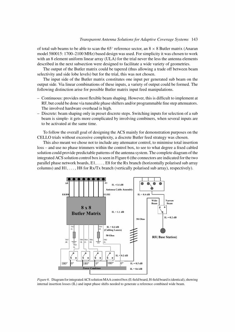
This also meant we chose not to include any attenuator control, to minimise total insertionloss – and use no phase trimmers within the control box, to see to what degree a fixed cabledsolution could provide predictable patterns of the antenna system. The complete diagram of theintegrated ACS solution control box is seen in Figure 6 (the connectors are indicated for the twoparallel phase network boards, E1, . . . , E8 for the Rx branch (horizontally polarised sub arraycolumns) and H1, . . . , H8 for Rx/Tx branch (vertically polarised sub array), respectively).
Figure 6. Diagram for integrated ACS solution MAA control box (E-field board, H-field board is identical), showinginternal insertion losses (IL) and input phase shifts needed to generate a reference combined wide beam.

144 P.C.F. Eggers and B. Krøyer
Figure 7. MAA implementation of an integrated and flexible ACS.
While the internal cabling in the box can be fairly easily controlled with respect to phase(electrical length) with a precision of 0.2◦, there is an extra complexity regarding the feed fromthe box to the antenna elements. Here eight parallel cables need to connect the control boxwith the antenna array, all with controlled phase (electrical length). Due to the CELLO trialimplementation where the control box was to be put on the roof and the array on the mast (seeFigure 7), the connecting cables needed to be of a length of few meters (4 m Suhner Sucoflex).With this length it is very difficult to produce equal electrical length, thus the cables wheredelivered with phase trimmer connectors, to allow trimming to same electrical length with aprecision of 0.3◦. Consequently, only the desired control box phase shifts would effectively beinduced at the antenna array. Furthermore, the long cables can have problems with differentphase changes due to different bending of the cables. While the Sucoflex cables are high qualitycables and provide low phase fluctuation with bending, the cables were as precaution strappedtogether so forcing all cables to be subject to approximately same mechanical deformationand resulting in similar phase shifts changes.
As will be described in the next subsection, single beams (achieved by activating one of theButler matrix input ports) were feed nominally with 180◦ phase shift compared to neighbourbeams, to allow combination to a wider 65◦ reference beam. These phase shifts were hardimplemented via differences in the electrical length of the internal cabling, see Figure 8.
If we, alternatively consider an optimised production ACS for an integrated solution, somechanges to the adopted CELLO butler matrix approach could be made with respect to:
– Phase steering architecture: possibly discrete pr. antenna element (instead of integratedfor the whole MAA in the Butler matrix) and imbedded within each element (sub-array).This would allow the control box circuitry to be placed on a back plane to the antennaarray. Thus minimizing the connecting cable lengths considerably and possible facilitatesimplementations with fixed cabling, without the use of cable phase trimmers (i.e. reducedproduction and assembly/calibration costs).
– Phase steering strategy: allowing ad-hoc beam shaping if based on either programmablefine step attenuators or tuneable/step phase shifters.
The implemented CELLO ACS control box for the integrated solution was conformancetested with respect to isolated control box specifications in the laboratory, before the completeACS use at the ELISA test centre for system conformance test.

Transparent Antenna Solutions for Adaptive Coverage Systems 145
Figure 8. Integrated ACS solution MAA control box with snapshot of the first layer (left) and layer 2 and 3 (right).Only layer 2 is visible (layer 3 is identical and hidden below). Layer 2 is for the horizontal polarisation (E1..E8.)and layer 2 for the vertical polarisation (H1..H8).
From the measurements of the selected single beams through the control box (see Figure 6),only the output phase states are given in Table 2. The amplitudes were within 0.3 dB toleranceand not recorded. All measurements were made with respect to E1 and H1 (as appropriate) asreference points. All Sucoflex cables were calibrated for equal phase shift (with in 0.3◦ usingthe integrated phase shifters provided in the connectors). The measured total phase shifts inTable 2, are dominantly due to the Butler matrix and internal cabling, see Figure 6. It followsfrom Table 2 that worst-case phase accuracy is within about 2◦ while most are with in approx.0.5◦. This is sufficient accurate for the main beam generation and predictable side-lobe levels.
The 1:2 switches in the control box where of similar type as those used in the simpleswitched solution described in the previous section. The 1:4 switch in the integrated solutioncontrol box is slower (nominal max. 15 ms switching time). This is well under the critical 480ms limit. However, due to several switches being activated simultaneously, large currents weredrawn, thus stressing the power supply. This caused some additional delay, so the complete
Table 2. Measurement of MAA control box phase states (output pr. element E1..E8) for different beam generations(input TR3..TR6) vs. nominal desired phase states
Output of control box. [deg] E1 E2 E3 E4 E5 E6 E7 E8
Beam 5. TR3 measured 0.00 69.59 136.22 201.93 270.00 338.20 45.81 112.50
Beam 5. TR3 expected 0.00 67.50 135.00 202.50 270.00 337.50 45.00 112.50
Beam 4. TR4 measured 0.00 21.85 45.76 67.07 89.88 111.07 135.03 157.52
Beam 4. TR4 expected 0.00 22.50 45.00 67.50 90.00 112.50 135.00 157.50
Beam 2. TR5 measured 0.00 −23.30 −44.26 −70.63 −90.66 −114.60 −135.36 −160.67
Beam 2. TR5 expected 0.00 −22.50 −45.00 −67.50 −90.00 −112.50 −135.00 −157.50
Beam 1. TR6 measured 0.00 −65.88 −134.00 −202.20 −269.84 −337.26 −43.68 −110.52
Beam 1. TR6 expected 0.00 −67.50 −135.00 −202.50 −270.00 −337.50 −45.00 −112.50

146 P.C.F. Eggers and B. Krøyer
switching process could amount up to 50 ms (which still remains well below the 480 ms criticallimit set by ELISA’s trail site transceivers. The test centre system test and the field trial didnot spur any problems either).
The nominal total insertion loss of 5 dB was measured at 5 dB ± 0.5 dB and was acceptableseen with respect to the link budget at the trial site (a higher antenna gain could also compensatefor this).
The control box impedance matching towards the BS transceiver end was measured witha resulting worst-case reflection coefficient of � < −20 dB. This transforms to a VSWR= (1 + �)/(1 − �) < 1.22, which is sufficiently low not to cause problems with the BStransceivers.
The following subsections describe the complete ASC MAA system beam generationperformance.
5.2. MODULAR ANTENNA ARRAY AND BEAM SHAPING
For the second trail a phase array solution was used – in principle allowing a very wide range ofnon pre-determined adaptations. In this context, CELLO has introduce the Modular AntennaArray (MAA) concept [12]. This idea is fairly new in civilian context, allowing for tailor-suitedarrays with site-specific geometries, based on the ‘Lego brick’ principle [15]. However, theaspect of optimising array geometry based on site-specific needs is a study by it self and wasnot performed in CELLO due to time constraints.
The overall requirements for the MAA were:
– Single element (sub-array) construction to allow flexible array geometry (future application)– Complete MAA gain comparable to currently use commercial fixed sector antennas (trial
constraints)– Element pattern at least as wide as the 65◦ reference fixed sector antenna (trial constraints)– Polarisation diversity support (trial constraints)
Detailed radio and mechanical requirements were also set, to assure proper functionality ofthe MAA in the CELLO trial [12]. For instance, low coupling needs to be ensured, so elementswill not change radiation behaviour too drastically when relocated in a different position in anarbitrary array-geometry using the Lego-brick principle.
For simplicity the complete MAA was chosen as an eight column uniform linear array(ULA) in the second CELLO trials. To comply with the over-all gain requirements eachcolumn was designed as a sub-array of 1 × 4 dual-polarised elements (Figure 7 right).
The antenna elements themselves were constructed as stacked patch type with the bottom(feed) patch driven with a tip [12]. For this type of antenna the matching and feeding networksare completely separated from the radiation region of the structure (the ground plane of theantenna offers very high isolation) minimizing the influence of those structures to electricaland radiation characteristics of the antenna.
The requirement of production repeatability (i.e. performance similarity) is especiallyimportant as the sub-arrays would be produced individually and not in one process as wouldbe the case in many standard ULA designs. If a standard design is a bit off the design goals, itis likely that all columns are influenced the same. For the MAA case the individual sub-arraysmay experience different changes and thus result in more unpredictable array performance.
For predictable array behaviour, especially the phase response over the bearing region ofinterest −65◦ around the 90◦ broad side to bore-sight direction needs to be very similar (e.g. for
Transparent Antenna Solutions for Adaptive Coverage Systems 147
coherent summation for the main lobe, less than 22 12◦ deviation is desired; The requirements
are tougher for controlled cancellation of side lobes). The amplitude responses also need tobe very similar over the same bearing region, but this is normally easier to achieve. A patterndifference of sub-arrays of around 1 dB or less is not critical. Measuring each sub-arrayindividually in an anechoic room revealed that the target phase and amplitude patterns weremet with amplitude differences around 1 dB worst case and phase differences around 15◦ worstcase (at edges of central 65◦ target region). Mutual coupling between sub-arrays was found tobe below −20 dB [12].
In a fully developed situation where the MAA Lego brick principle would be utilised toeither allow a wide variety of standard array geometries or ad-hoc site-specific array geometryadaptation, extra mechanical requirements appeared for the assembly:
– Mechanical array assembly architecture should allow easy reconfigurability, e.g. like snaplocks, discrete step mounting location markers/fixture groves in the tubing or support bars,etc.
– The assembly technology should support sufficient tolerances and flexibility to avoid costlycalibration for each implemented geometry.
If this is achieved, the roof technician may change array geometry on the spot for immediateoperation, without having to take the MAA down to a measurement facility for recalibrationfirst.
5.2.1. Beam PerformanceAs the CELLO integrated ACS was only applied to the focussing test area, it appeared fournarrow beams can sufficiently support beam scanning across the centre part of the 65◦ referencesector. The fixed sector 65◦ reference also had to be supported by implementing a wider beam.This beam could be created using a sum of individual beams, i.e. activating several inputs ofthe Butler matrices at the same time (see Figure 6). For this superposition of sub beams tobe successful it has to take the SINC beam shape into account, which is causing each sidelobe shifted 180◦ compared to the next one. For coherent summation of sub beams, neighbourbeams had to be feed 180◦ offset, in this way the first side lobe of a beam adds in phase with themain lobe of the neighbouring beam, see Figure 6. Making small adjustment to this alternating0◦, 180◦ feed, allows trade offs to be made between beam flatness (allowable ripple) versusroll off (sharp edges) of the combined pattern.
The closest possible column spacing (due to physical width of the sub arrays) of 95 mmwas chosen (0.55 λ apart at 1747 MHz). This should produce the four desired narrow beamsand one wider beam using the feed network displayed in Figure 6. In each case the states forantenna diversity branches Rx/Tx and Rx were the same. The resulting beams were nominally:
i) 1L, narrow beam (10◦) in direction 97.2◦,ii) 2L, narrow beam (10◦) in direction 112.0◦,
iii) 1R, narrow beam (10◦) in direction 82.8◦,iv) 2R, narrow beam (10◦) in direction 68.0◦,v) sum of six beams i.e. from 1–3 L to 1–3 R, wide beam (65◦) in direction 90◦.
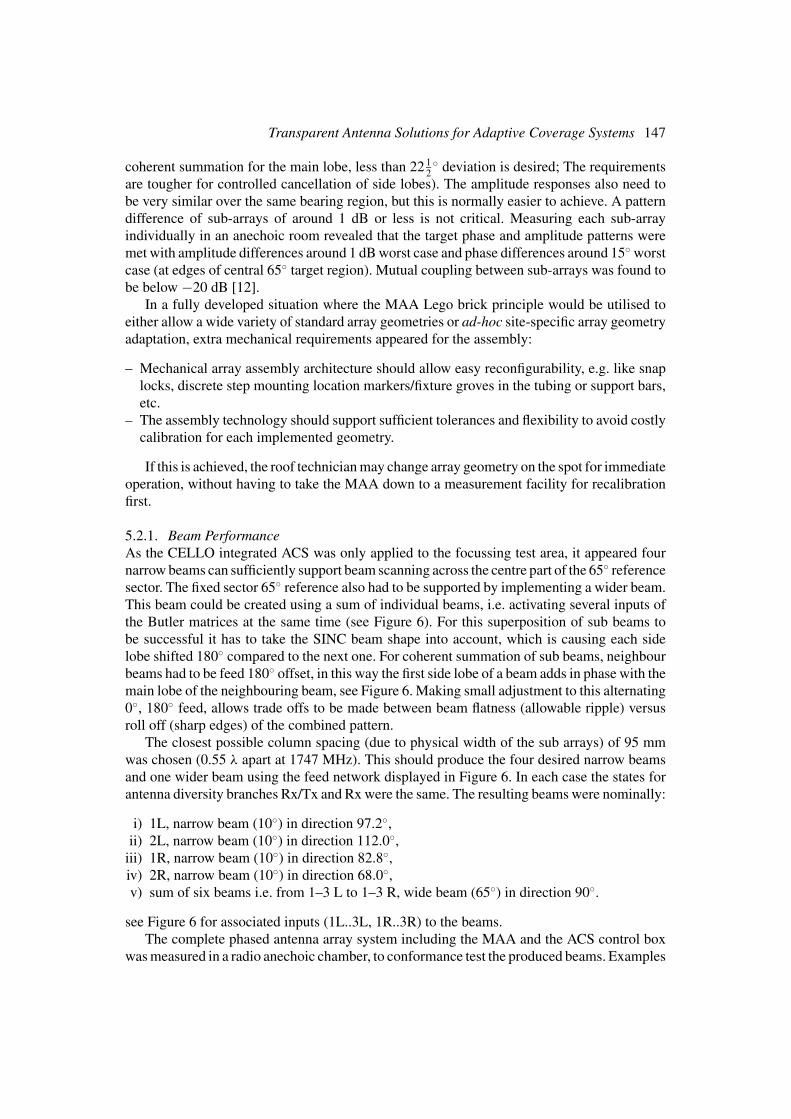
see Figure 6 for associated inputs (1L..3L, 1R..3R) to the beams.The complete phased antenna array system including the MAA and the ACS control box
was measured in a radio anechoic chamber, to conformance test the produced beams. Examples

148 P.C.F. Eggers and B. Krøyer
Figure 9. Measured vertical polarisation patterns of a single beam (left) and wide beam (right) at 1747 MHz, ofcomplete MAA and control box ACS in a radio anechoic room.
of a measured narrow beam and the wider reference beam are shown in Figure 9. This showshow the beam essentially displays the expected shape and orientation.
Note that the first side lobe of the narrow beam is only about −13 dB down from the mainlobe, due to no tapering was applied at the output end of the Butler matrix (i.e. rectangularwindowing causing a SINC shaped pattern). However, it is such a narrow side lobe so theeffective average pattern [16] is expected to just broaden the shoulders of the perceived patternslightly, due to the directional spreading [16] of the radio signal received by the MAA.
Following these measurements the complete integrated MAA ACS system was approvedfor installation at the trial site, see Figure 7.
6. Trial Results
CELLO performed two field trials involving the ACS. The first trial tested the simple switchedACS solution in the three different test scenarios described in Section 3. The second trail testedthe integrated solution ACS in the focussing test scenario.
As this paper is mainly focussing on the antenna solutions them selves and the constructionand radio performance of these solutions have been discussed in the previous sections – thesystem performance based field trail results will only be touched up on briefly in this section.More detail on the CELLO trial results is given in an accompanying paper [2] in this specialissue.
The outcome of network plan changes was investigated by field measurements [2, 15]. Itwas observed that the changes were occurring as predicted within the limits of the accuracyof the prediction tool [13], which indicated proper functioning of the antenna control chain.
To facility feedback information on coverage, signal level probing accuracy was investi-gated in trial one. The terminal feed back information compared to actual power level recordedby field strength measurements, yielded mean and average accuracy in about 3 dB mean and4 dB RMS error [15]. This has to be compared to typical prediction accuracies of 5 and 15 dB

Transparent Antenna Solutions for Adaptive Coverage Systems 149
by propagation models in standard planning tools. I.e. an obvious potential for increased cov-erage estimation accuracy suitable for network controlled antenna manipulations, suing anACS.
Due to restrictions on possible service influence and security/privacy policy towards cus-tomers in the live network used for the trials, different network plans could not be changedinstantaneously or evaluated on-line in trial 1 (thus also prohibiting test of any real automatedMGIS controlled network manipulations). Instead received Rx-levels were recorded at testpoints during 1 week with a normal fixed sector antenna setting and on the following weekwith an antenna setting corresponding to increased traffic. This allowed average comparisonof the different network plans [2, 15].
From each test scenario, terminal level measurements were collected along measurementroutes in side a designated test hot spot area, by the a group of test persons. These measurementswere then analysed off-line against predicted Rx-levels2 [15].
The trials proved the signal manipulation due to desired coverage changes was indeedperceived on the ground. For example for an off sector test (beam not supporting trial hot spot)[2, 15]:
– Rx level readings between 20–30 were found in 9 test points out of 50 and no higher levelswere present.
On switching the coverage area on (beam supporting the trial hot spot) [2, 15].– Rx levels readings of 20–30 were found in 10 test points while additionally Rx levels >30
were found in 32 test points. Thus total of 42 out of 50 test point with good reception
i.e. an increase of a factor 4 in perceived connections, constituting the selectivity the ACScould perform at the trial sites.
The pattern control operation took about one minute due to the slow set-up of the controlconnection by the GSM modem. However, since the time constant of network plan changes isconsiderable longer, this is not a severe problem [15].
In trial 2 there were not the same restrictions regarding instantaneous changes to thecoverage, as in trial 1. So trial 2 also performed test if the switching between two antennalobes would cause dropped calls [15]. It was found feasible to switch the beams gradually intrial 2 to make the signal changes more smoothly (scanning the intermediate beams till thedesired beam was reached).
A Data Analyser Module (DAM) was used to visualise this tracking of a moving hotspot using the progression of the four different narrow beams following a measurement routespanning over a 60◦ section as seen form the ACS equipped BS [15]. The test showed thatthe DAM was capable of performing the analysis of network data and creating a network planschedule by correct selecting best covering narrow beam and that the ACS could effectivelybe used for running the schedule by executing the desired changes at the MAA (i.e. physicallychanging the coverage to desired narrow beam) [15].
The diversity soft transition possibility discussed in Section 2.4, was not tested in trial 1 ortrial 2. However, due to the experience from the finer resolution beams in trial 2, it is believedusing this strategy in a simple switched solution also can provide a more graceful adaptationto changes in the coverage.
2 Rx level in dBm + 110.

150 P.C.F. Eggers and B. Krøyer
7. Conclusions
The CELLO project has introduced a vision of flexible capacity through transparent antennamanipulation at the radio interface level. The project provides a method (hardware and soft-ware) to control network capacity based on intelligent antenna systems. The demonstratedACS concept is considerably less expensive than adaptive antenna solutions proposed earlier.The ACS concept is able to provide more local capacity according to need. The congestion ofnetworks during special events (e.g. football matches) could be avoided in many cases, whichmeans increased revenues for the operators without the need to install new base stations. In-creasing this ‘per mast’ capacity may also alleviate potential future problems related to publicfear of BS masts.
This paper presents the concepts and implementations of ACS antenna solutions investi-gated within the CELLO project. The ACS prototypes developed for trial 1 and 2 show thefeasibility of the ideas, through two different vendor transparent antenna system solutions, dif-fering in degree of complexity and potential. The antenna systems and control box have beenconstructed according to desired specifications and tests in a radio anechoic chamber provedthe proper functionality. Furthermore, the interface to the network hardware (i.e. control box)was conformance tested and approved at the network operators test centre, with respect toco-operability with the base station transceivers. The final field trials also confirmed properfunctionality of the complete ACS solution. I.e. proving switched antenna solutions with upto 50 ms switching delays, can be installed without disturbing the operation of the base stationtransceivers in a live GSM network.
For the first trial the achievable selectivity in Rx-level was around a factor 4, showingexpected beam to coverage mapping. The terminal feed back accuracy on power level wassignificantly better (within about 5–10 dB) than power levels estimated from a blind predic-tion model. Thus showing the potential for dynamic coverage planning based on networkinformation.
In the second trials the beams where more selective and gradual progression of sub beamsshowed effective in providing a graceful change over between coverage states. Thus allowingfor very focused coverage plans to be applied without introducing sudden mass drop callsduring the change over.
Acknowledgements
The current paper is based on work supported by the EU CELLO project – IST-200025382[1]. The purpose of CELLO is to utilise mobile location information for capacity optimisationin mobile networks. The hardware (HW) development, construction and µ-control of thecontrol/steering boxes and anechoic chamber calibration of the MAA have been performed byAalborg University, Denmark. National Technical University of Athens, Greece has undertakenthe HW design and construction of the MAA, as well as ACS interfacing software. The DAMwas designed and implemented by VTT, Finland. The trial network was provided by Elisa Oy,Finland, whereas the trials themselves where conducted by VTT.
References
1. CELLO-project http://www.telecom.ntua.gr/cello/.

Transparent Antenna Solutions for Adaptive Coverage Systems 151
2. S. Horsmanheimo, H. Jormakka, and J. Lahteenmaki, “Location-Aided Planning in Mobile Network–TrialResults”, Kluwer Wireless Personal Communications, special issue on Cellular and Wireless Location BasedTechnologies and Services, 2004.
3. J.H. Winters, “Smart Antennas for Wireless Systems”, IEEE Personal Communications, Vol. 1, Feb. 1998,pp. 23–27.
4. L.C. Godara, “Applications of Antenna Arrays to Mobile Communications, Part I: Performance Improve-ment, Feasibility, and System Considerations”, Proceedings of the IEEE, Vol. 85, No. 7, pp. 1031–1060,1997.
5. S.C. Swales, M.A. Beach, D.J. Edwards, and J.P. McGeehan, “The Performance Enhancement of MultibeamAdaptive Base-Station Antennas for Cellular Land Mobile Radio Systems”, IEEE Transactions On VehicularTechnology, Vol. 39, No. 1, pp. 56–67, 1990.
6. S. Sharma, A.G. Spilling, and A.R. Nix, “Adaptive Coverage for UMTS Macrocells Based on SituationAwareness”, in Proceedings of the IEEE VTC, Rhodes, Greece, pp. 2786–2790, Spring, May 6–9, 2001.
7. T.V. Nguyen, P. Dassanayake, and M. Faulkner, “Use of Adaptive Sectorisation for Capacity Enhancementin CDMA Cellular Systems with Non-Uniform Traffic”, Kluwer Wireless Personal Communications, Vol. 28,No. 2, pp. 107–120, 2004.
8. “Metawave Antenna Solution Improves Call Quality, Cell Site Capacity”, Mobile Phone News, March 11,1996, p. 5. Metawave Spotwave System, http://www.metawave.com/, now out of business.
9. AirNet AdaptaCell http://www.aircom.com/pr supercapacity.htm.10. ArrayComm IntelliCell ‘IntelliCell : A Fully Adaptive Approach to Smart Antennas’, http://www.arraycomm.
com/docs/intellicell.pdf. [email protected], WP-ISA-031502-2.0.11. Y. Li, M.J. Feurstein, and D.O. Reudink, “Performance Evaluation of a Cellular Base Station Multibeam
Antenna”, IEEE Transactions On Vehicular Technology, Vol. 46, No. 1, pp. 1–9, 1997.12. A.D. Garetsos, P.C.F. Eggers, and E.D. Sykas, “Design & Implementation of an Antenna Module (used as a
“brick” for the construction of an array of arbitrary shape) for Mobile Networks”, in Proceedings of MobileLocation Workshop MLW03, Aalborg University, Denmark, http://cpk.auc.dk/mobilelocwksp03/, May 22–23,2003.
13. E. Aarnæs and S. Holm, “Tuning of Empirical Radio Propagation Models –Effect of location accuracy”, KluwerWireless Personal Communications (Special Issue on Cellular and Wireless Location Based Technologies andServices), 2004.
14. ‘ACS Technical Documentation’, CELLO deliverable CELLO-WP4-CPK-D17-005-Apr & “ACS TechnicalDocumentation Appendix for Trial 2. MAA – MAA SW-BOX”, CELLO deliverable CELLO-WP4-CPK-D17a-006-Apr. Public documents: http://www.telecom.ntua.gr/cello/documents/.
15. “Final Report”, CELLO deliverable CELLO-WP1-VTT-D36-006-Apr. Public document.16. P.C.F. Eggers, “Angular Propagation Descriptions Relevant for Base Station Adaptive Antenna Operations”,
Kluwer Wireless Personal Communications (special issue on Space Division Multiple Access (SDMA)),Vol. 11, No. 1, pp. 3–29, 1999.
Patrick C.F. Eggers was born in Stockholm, Sweden, in 1957. He received an M.Sc.E.E.degree from Aalborg University, Aalborg, Denmark, in 1984 and the Ph.D. in 2003. He has beenemployed at Aalborg University since 1984, mainly as a full-time researcher in mobile radiocommunications. His current position is associate professor at the Center for TeleInfrastruktur

152 P.C.F. Eggers and B. Krøyer
(CTIF), Aalborg University. He has been an active participant in the COST207 and COST231,COST259 working groups on propagation.
He worked in Wellington, New Zealand, from October 1988 to November 1989 for TelecomNew Zealand. He was responsible for the angular propagation work performed under the RACEII project, TSUNAMI – and task leader on many other industrial and EU projects, dealing withmulti antenna propagation. He is one of the initiators and the coordinator of the, English-taught, international M.Sc.E.E. course at Aalborg University, specializing in mobile radiocommunications. He is the research coordinator of the Antennas and Propagation Divisionsof CTIF and project leader on various research projects involing industrial partners. His maininterest lies in the field of propagation and mobile communications, lately with focus on MIMOand UWB.
Ben Klauman Krøyer received his Electro Technicians Diploma from Odense Technicum,Denmark, in 1998. He has been employed at Aalborg University, Institute of Electronic Sys-tems, since 1999, taking care of a variety of hardware tasks within the components workshop till2001, where after he has been responsible for hardware and firmware design and constructionof the CELLO ACS controller boxes. In 2004, he joined the institutes’ electronics workshop.His interests are general hardware and software development of prototype platforms.