Embed Size (px)
Citation preview
Transmitter Compliance for Europe and North America
Written by: Nicholas Abbondante, EMC Engineer, Intertek
Intertek Testing Services NA, Inc 70 Codman Hill Road, Boxborough, MA 01719
[email protected] 800-WORLDLAB www.intertek-etlsemko.com
Transmitter Compliance for Europe and North America
www.intertek-etlsemko.com 1
Table of Contents
Introduction……………………………………………………………………… 2 Regulatory Agencies……………………………………………………………2 Transmitter Approval Process……………………………………………………3 North American Approvals (United States and Canada)…………………….3 North American Labeling and Marking………………………………………4 North American Information to User…………………………………………5 European Union Approvals and Marking…………………………………… 5 European Union Information to User…………………………………………6 Changes to Existing Equipment/Acquired Technology Product Development…………………………………………………………7 Testing…………………………………………………………………………….7 Types of Tests…………………………………………………………………..8 Sample Configuration………………………………………………………….8 RF Exposure Testing……………………………………………………………12 SAR Testing…………………………………………………………………..13 MPE Evaluation, Calculation, Computation………………………………..14 Certification Documentation…………………………………………………….14 Emissions Designators………………………………………………………….15 Unique Antenna Connectors………………………………………………….16 Restricted Bands………………………………………………………………..16 Modular Approvals……………………………………………………………….17 Conclusion………………………………………………………………………..18
Transmitter Compliance for Europe and North America
www.intertek-etlsemko.com 2
Introduction
The use of transmitters is expanding at a breathtaking pace. They have long been used in communications devices such as walkie-talkies, pagers, and cell phones, and in applications such as garage-door openers and radio-controlled toys. Now, transmitters are being put to work in a host of new areas. Remote household heating controls and Bluetooth mobile phone headsets are just two examples that appeal to today’s consumers. Remote utility meter-reading devices and RFID tags are typical of emerging business applications. However, many pitfalls exist for OEM engineers who are designing transmitters into their products. If they lack deep expertise in the transmitting technologies or if they are not familiar with regulatory constraints overseas as well as in domestic markets, their companies can easily run afoul of the law – or at least face big delays in launching new products. The regulatory approval processes for transmitting devices are stringent, and becoming more so. There are two main reasons for that. First, transmitters can and do interfere with the normal operation of other devices around them when they are in use. Second, the regulatory agencies that manage the electromagnetic spectrum in each country face the challenge of coordinating the use of transmitter frequencies. Otherwise, vital communications may be disrupted, such as search and rescue communications, police radio networks, radio and television broadcasts, and aircraft navigation. Although the regulatory agencies are anxious to streamline the approval process for transmitter-containing devices, it is an uphill battle and one that requires the cooperation and understanding of OEM engineers everywhere. In this white paper, Intertek-ETL Semko sets out to help OEM engineers make sense of the regulatory labyrinth. The paper describes the latest twists and turns in the approval processes in North America and in the European Union, points to the types of tests for which OEMs must prepare and reviews the documentation needed to obtain certification.
Regulatory Agencies
Agencies that regulate the spectrum in a selection of countries include:
• Australia: ACMA (Australian Communications and Media Authority)—http://www.acma.gov.au
• United States: FCC (Federal Communications Commission) Office of Engineering and Technology—http://www.fcc.gov/oet
• Canada: IC (Industry Canada) Spectrum Management Office—http://strategis.ic.gc.ca
Transmitter Compliance for Europe and North America
www.intertek-etlsemko.com 3
• European Standards: ETSI (European Telecommunications Standards Institute)—http://www.etsi.org
• European Spectrum Coordination: ERO (European Radiocommunications Office)—http://www.ero.dk
• New Zealand: RSM (Radio Spectrum Management)—http://www.rsm.govt.nz/ • Japan: MIC (Ministry of Information and Communications)—
http://www.soumu.go.jp/english/index.html
Transmitter Approval Process
North American Approvals (United States and Canada)
In the United States, the Federal Communications Commission (FCC) has developed a process to allow private, third-party certification bodies to act in the capacity of the FCC and to issue Grants of Authorization for transmitters. Each certification body, which also must be a test lab, may issue these grants within its scope of approvals—that is, for the standards where it has shown testing proficiency and competence. Industry Canada (IC), which works closely with the FCC and develops its transmitter regulations in sync with the FCC requirements, has adopted a similar process. The FCC calls these third-party labs Telecommunications Certification Bodies (TCB), while Canada calls them Certification Bodies (CB).
In addition to certification, some transmitters must have a license to be operated in the United States or Canada. This license serves to coordinate the frequencies used in specific geographical areas. The types of licenses range from an individual operator or amateur license, to a broadcast license, to a General User Radio License (GURL). The GURL applies to communications networks where the license is held by the operator of the network, not the user of the device. It also applies to devices used by large groups of people, such as CB radios and remote-control vehicles. Licenses to operate certified products in the U.S. can be obtained from the FCC’s Wireless Telecom Bureau’s Universal Licensing System (ULS) at http://wireless.fcc.gov/uls and licenses for operation in Canada can be obtained at http://sd.ic.gc.ca/engdoc/main.jsp (“Spectrum Direct”® in English). Grants of Authorization issued by the FCC or a TCB correspond to a unique product number called an FCC ID. The FCC ID is composed of a three-character Grantee Code, followed by a Product Code of up to 14 characters, selected by the company applying for certification. The Grantee Code identifies the company the grant is associated with. It is obtained from the FCC or a TCB for a small fee and is used by the organization for all subsequent applications. The Product Code is usually selected by the applicant company based on the model number of the product being certified, and it can be composed of alphanumeric characters and dashes. The product labeling must bear the proper FCC ID in order to be legal for sale in the U.S. Selling a transmitting product without a valid FCC ID
Transmitter Compliance for Europe and North America
www.intertek-etlsemko.com 4
number or with an incorrect FCC ID number is illegal and is subject to fines and penalties enforced by the FCC. The Certificates issued by Industry Canada or the CBs use a similar unique product number, called a certification number. This number is comprised of a Company Number (CN), usually four to five characters long, which identifies the company associated with the certified product, and a Unique Product Number (UPN) eight characters long. A Company Number can be obtained from Industry Canada by emailing [email protected] and providing the full company name, mailing address, telephone number, fax number, contact name, and email address of the requesting company.
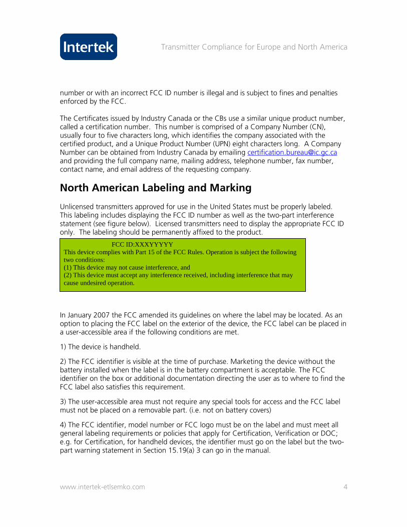
North American Labeling and Marking Unlicensed transmitters approved for use in the United States must be properly labeled. This labeling includes displaying the FCC ID number as well as the two-part interference statement (see figure below). Licensed transmitters need to display the appropriate FCC ID only. The labeling should be permanently affixed to the product.
In January 2007 the FCC amended its guidelines on where the label may be located. As an option to placing the FCC label on the exterior of the device, the FCC label can be placed in a user-accessible area if the following conditions are met.
1) The device is handheld.
2) The FCC identifier is visible at the time of purchase. Marketing the device without the battery installed when the label is in the battery compartment is acceptable. The FCC identifier on the box or additional documentation directing the user as to where to find the FCC label also satisfies this requirement.
3) The user-accessible area must not require any special tools for access and the FCC label must not be placed on a removable part. (i.e. not on battery covers)
4) The FCC identifier, model number or FCC logo must be on the label and must meet all general labeling requirements or policies that apply for Certification, Verification or DOC; e.g. for Certification, for handheld devices, the identifier must go on the label but the two- part warning statement in Section 15.19(a) 3 can go in the manual.
FCC ID:XXXYYYYY This device complies with Part 15 of the FCC Rules. Operation is subject the following two conditions: (1) This device may not cause interference, and (2) This device must accept any interference received, including interference that may cause undesired operation.

Transmitter Compliance for Europe and North America
www.intertek-etlsemko.com 5
Industry Canada requires certified equipment to be labeled as follows: (a) the certification number, prefixed by the term “IC:” (b) the manufacturer's name, trade name, or brand name. (c) a model name or number.
Transmitters that do not require certification by Industry Canada are labeled in the same way, except that the certification number, item (a), is replaced by a designation such as “Canada 310,” which indicates compliance to Industry Canada’s RSS-310 standard.
North American Information to User 1) 15.21: Changes or modifications not expressly approved by the manufacturer could void the user’s authority to operate the equipment. 2) 15.105(a) This equipment has been tested and found to comply with the limits for a Class A device. 15.105(b) This equipment has been tested and found to comply with the limits for a Class B device. (More detailed instructions must follow regarding interference.)
European Union Approvals and Marking The European Union (EU) does not require certification of devices that contain transmitters. Many transmitters are handled via declaration of conformity with harmonized standards and essential test suites that were specially written for each category of transmitter. Harmonized standards are standards that have been written by the European Telecommunications Standards Institute (ETSI), published in the Official Journal of the European Union, and that have been accepted without modification by all member nations of the EU. Products with transmitters that comply with harmonized ETSI standards with essential test suites can affix the CE mark, if they meet all other product requirements such as safety as well. Products may be imported for sale in European Union member countries once a copy of the declaration of conformity is provided that references the appropriate standards. Sometimes, member nations of the EU impose special transmitter requirements, such as lower output power in certain bands of operation, in order to protect legacy systems. In these cases, the transmitter must not exceed the lowest power limit or otherwise in-country notifications must be performed. When an unharmonized standard or a harmonized standard which does not contain a list of essential test suites is used to demonstrate compliance, a Notified Body opinion must be obtained. A Notified Body is a third-party test lab or agency that has been accredited to issue opinions on compliance to standards within its scope. After a Notified Body opinion is obtained, product must then be marked with the CE mark bearing the number of the
Transmitter Compliance for Europe and North America
www.intertek-etlsemko.com 6
Notified Body. An in-country notification to the country’s regulatory agency also must occur at least 30 days before a product may be imported for sale. Medical devices that contain a transmitter must apply a mark to warn users of possible interference. In addition, products tested for compliance to unharmonized standards must apply the EMC “alert” mark. Examples of the “alert” mark, medical device transmitter mark, and CE mark without Notified Body opinion number appear below.
CE Mark Medical Device Alert
In Europe, and for medical devices in the United States, compliance of the transmitter is not based solely on testing of the transmitter outputs. Some level of immunity to external disturbances also is required. Types of immunity tests for disturbances include electrostatic discharges, radiated emissions, surges induced on the power lines, emissions injected on the power line, magnetic fields at the frequency of the AC network, and voltage dips and brownouts. These tests are mandated for devices containing transmitters in ETSI EN 301 489-x. They are similar to the tests called out for medical devices in IEC 60601-1-2 and for other product types, such as ITE equipment in standards such as EN 55024. The main difference between ETSI EN 301 489x and the other European immunity standards is that transmitter performance is considered during the test disturbance. To successfully complete the test, the transmitter cannot be caused to transmit unexpectedly due to the test disturbance, and the receiver may not receive a signal due to the test disturbance when no actual signal was sent. For this reason, some thought must be given to implementing a method to monitor the transmitter behavior during the test, although care should be taken that this method of monitoring does not itself allow the test disturbance to affect system operation.
European Union Information to User The same CE marking on the product, including any Notified Body number and “alert mark” for unharmonized spectrum, should be repeated on the product packaging and in user information. Additionally, the packaging must indicate (usually in a compact tabular format) which EU member states do and do not accept operation of the transmitter.
Transmitter Compliance for Europe and North America
www.intertek-etlsemko.com 7
Information to the user must also include:
• Intended use of the equipment.
• Declaration of conformity to the essential requirements.
• Potential restrictions or requirements for authorization of use in certain member states.
Contact information for spectrum regulators is available at the ERO Web site: www.ero.dk. The same site provides guidance on harmonized and unharmonized spectrum and on country-by country restrictions that may exist for short-range transmitters.
Changes to Existing Equipment/Acquired Technology Over the course of time, radio transmitters are subject to modifications, expanded capabilities and new applications. In order to accommodate both technical and administrative changes, a number of procedures have been established by the FCC and Industry Canada and, to a lesser extent, the EU. Each jurisdiction may use a different name for a process.
• Retesting—subset of original testing • Permissive changes
• Class I permissive change—no filing required; retain records of change and testing.
• Class II permissive change—requires filing with the FCC and Industry Canada. • Class III permissive change— Software-Defined Radios (SDRs) (does not exist
in Canada). • EU—Declaration of Conformity/Notification. • Change of ownership of Grantee (FCC) or change of certificate holder (Canada)
Change in ID (FCC 2.933) or multiple listing (Canada) permits a filing to use an existing certification where the grant is held by another company, but the filing company should market the device under its own trade name/company logo. In this situation, filing typically requires a letter from the grant-holding company that authorizes the filing company to market its device, as well as a letter from the applying company declaring which device is being marketed and what are the details of the marketing. Photos of the intended label and the intended chassis changes, if any, are also required.
Product Development When developing a new transmitter, it is not necessary to ensure that the device meets the applicable regulations throughout the development process. Products only need full approvals when being marketed. However, an experimental license may be required before beginning development of products operating on certain protected frequencies, such as the frequency bands the FCC has allocated for licensed operation.

Transmitter Compliance for Europe and North America
www.intertek-etlsemko.com 8
Likewise, many products are still in development when being displayed at trade shows, or the product may be certified, but an unapproved prototype is the only available sample for demonstration. In these cases, the FCC and Industry Canada allow demo use if the product is clearly labeled for demo use or as a prototype not covered by the existing certification. Examples of suitable label text for these cases are shown below.
• The device has not been authorized as required by FCC rules. This device is not, and
may not be, offered for sale or lease, or sold or leased, until authorization is obtained.
• Prototype. Not for sale. In any case, it is important to note that product development/demo use is on a non-interference basis.
Testing: Types of Tests
Transmitter Test Suites RF Output Power This test measures the total output power of the operating frequency of the transmitter. A conducted emissions test can be performed if the device has an antenna port. If the device has an integral antenna, a radiated emissions test can be performed. European transmitters and licensed transmitters in the United States and Canada are tested using the path loss method. The emissions detected from the tested device are scaled using a signal generator and a transmit antenna, to the equivalent power required to duplicate the detected emissions. This method is intended to minimize any anomalies of path loss due to reflections or attenuations in a test site, or due to distance. When the path loss method is not used, the field strength measured at a specific distance is compared to the limit. (See diagram to the right.)
Transmitter Compliance for Europe and North America
www.intertek-etlsemko.com 9
Power Spectral Density This test measures the amount of power in a specific frequency segment. It is used for wideband transmission systems to ensure that the power is sufficiently spread over the frequency.
Spurious Conducted Emissions, Antenna Port This test measures unintended emissions, including harmonics, at the antenna port of the transmitter. Unintended emissions cannot exceed the level of the intended emissions of the transmitter. Another possible test is for intermodulation, which uses multiple tones at the low and high ends of the transmitter’s passband to test for signals generated by the interaction of the tones. This test is used on amplifiers, combiners, or other devices with multiple simultaneous carriers.
Spurious Radiated Emissions, Enclosure Port This test measures the unintended emissions of the radio enclosure or the radio with an integral antenna or a detachable antenna. Unintended emissions cannot exceed the level of the intended emissions of the transmitter. European transmitters and licensed transmitters in the U.S. and Canada are tested using the substitution method. In this method, the emissions detected from the tested device are duplicated using a signal generator and a transmit antenna, and the equivalent power required to duplicate the detected emissions is compared to the limit. The intention is to minimize any anomalies of path loss due to reflections or attenuations in a test site or due to distance. If the substitution method is not used, the field strength measured at a specific distance is compared to the limit. Intermodulation tests may also be performed. Such tests use multiple tones at the low and high ends of the transmitter’s passband to test for signals generated by the interaction of the tones. Occupied Bandwidth This test quantifies the span of frequency that contains 99% of the power in the intended band occupied by the transmitter.
Frequency Stability This test determines that, over reasonable variations in voltage and temperature, the operating frequency of the transmitter will not drift out of the allocated band of operation.
Peak Excursion of the Modulation Envelope For wideband devices regulated by standards such as FCC 15.407 and RSS-210 U-NII (5 GHz band Wi-Fi), restrictions are imposed on the ratio of the peak excursion of the modulation envelope (using a peak hold function) and the maximum conducted output
Transmitter Compliance for Europe and North America
www.intertek-etlsemko.com 10
power. This restriction prevents excessive RF energy from being transmitted in a brief burst over a narrow part of the operating spectrum.
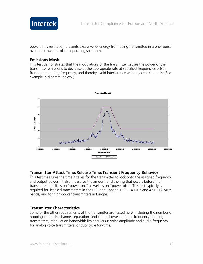
Emissions Mask This test demonstrates that the modulations of the transmitter causes the power of the transmitter emissions to decrease at the appropriate rate at specified frequencies offset from the operating frequency, and thereby avoid interference with adjacent channels. (See example in diagram, below.)
Transmitter Attack Time/Release Time/Transient Frequency Behavior This test measures the time it takes for the transmitter to lock onto the assigned frequency and output power. It also measures the amount of dithering that occurs before the transmitter stabilizes on “power on,” as well as on “power off.” This test typically is required for licensed transmitters in the U.S. and Canada 150-174 MHz and 421-512 MHz bands, and for high-power transmitters in Europe.
Transmitter Characteristics Some of the other requirements of the transmitter are tested here, including the number of hopping channels, channel separation, and channel dwell time for frequency hopping transmitters; modulation bandwidth limiting versus voice amplitude and audio frequency for analog voice transmitters; or duty cycle (on-time).
Transmitter Compliance for Europe and North America
www.intertek-etlsemko.com 11
AC Line-Conducted Emissions This test measures the unintended emissions at the AC power input port of the transmitter.
Adjacent Channel Power/Transient Power This test measures the amount of power that is generated in channels adjacent to the transmit frequency during operation and during “power on” and “power off.”
Receiver Test Suites European standards include a receiver test suite that covers receiver spurious emissions, or the unintended emissions generated by a transceiver in receive mode. This typically is the only required receiver test, although many standards include a list of recommended receiver performance tests. In the U.S., the FCC does not require testing of receivers that operate outside the range of 30–960 MHz, except for radar detectors and CB receivers. Receivers within 30–960 MHz in the U.S. are required to meet the Class B limits for digital devices. Industry Canada also requires that emissions from receivers do not exceed the general Class B limits for digital devices. Sample Configuration When you are preparing to test a transmitter, several considerations may be helpful in determining how to configure the transmitter. First, prototype variation should be taken into account. It can be useful to have a backup sample in case of unexpected operation. Often, transmitters do not operate on a continuous basis, and it is difficult to complete many of the required measurements in a reliable and timely fashion without modifying the transmitter to operate in as near to a continuous fashion as is possible. In cases where this modification has been made, the actual on-time, or “duty cycle,” during normal operation can be measured from an unmodified device. In addition to the typical and continuous operation, some transmitter tests, including frequency stability and transient frequency behavior, require unmodulated operation of the transmitter. Other characteristics of transmitter operation need to be considered as well. If the transmitter power can be controlled by the user, then control of the output power needs to be available so it can be tested at its minimum and maximum output powers. Also, it should be possible to disable any sweeping or frequency hopping. FCC and Canadian rules require that for transmitters that operate on a band wider than 10 MHz, individual channel control should be available to allow testing at the lowest, middle and highest points of the band of operation. Transmitters with an operating band of less than 10 MHz need only be tested at the upper and lower edges of the band, and
Transmitter Compliance for Europe and North America
www.intertek-etlsemko.com 12
transmitters with a band of operation of less than 1 MHz need only be tested on one representative channel. Frequency stability testing considers a varied input voltage. As a result, it will often require a way to supply either indirect AC or direct DC voltage access to the transmitter. In some instances, transmitters in large enclosures that do not fit into a temperature chamber need to be removed and tested alone.
Commonly, transmitting devices are designed to communicate with other specific devices and would not normally operate continuously without the presence of the other device. However, we recommend that these devices be tested as a system, or where one is used to exercise the other. Usually, it is possible to configure the device in such a way that it always “thinks” it sees a reply from the other transmitter, causing it to continue to transmit without the presence of the companion device. This method is preferable, as it allows for more accurate assessment of the emissions generated by the transmitter. Since subsequent modifications to the device often require retesting, and since the FCC and IC require that results remain within certain margins in order to file the certifications under the same ID number, this accuracy in original results can be useful. Another reason not to test paired transmitters together is that time can be lost if one of the samples exceeds the limits, requiring troubleshooting of both samples. FCC rules require that transmitters that have detachable antennas must be tested with the highest gain antenna of each type of antenna intended to be sold. After the test, any antenna of the same type as a tested antenna and of equal or lesser gain may be sold. For devices with variable output power, the lowest gain antenna of each type also must be tested.
RF Exposure Testing One important aspect of transmitter testing is the RF exposure evaluation of the product. The methods used vary based on the intended usage of the device and its output power. Studies have shown that the main electromagnetic hazards occur from the effects of tissue heating, such as microwave frequency heating or from extremely high-frequency ionizing radiation. Since transmitters do not operate at X-ray or gamma-ray frequencies, ionizing radiation is not a concern. Thus, the main focus of RF exposure compliance is on tissue heating.
Important points:
• Metabolism of human cells may be destroyed if cell is heated more than 1°C above normal body temperature.
Transmitter Compliance for Europe and North America
www.intertek-etlsemko.com 13
• FCC and the agencies of other countries have adopted RF exposure limits based on RF heating, or contact current, for portable (< 20 cm), mobile (> 20 cm), and fixed transmitters.
• Such limits are 10X below the 1°C level for “occupational” applications and 50X below the 1°C level for “general” applications.
• Methods include MPE (Maximum Permissible Exposure), SAR (specific Absorption Rate), Computational Modeling, Calculation
• Portable devices are subject to SAR measurement, using a “phantom” to simulate head or body shape, and fluids to approximate brain or muscle tissue.
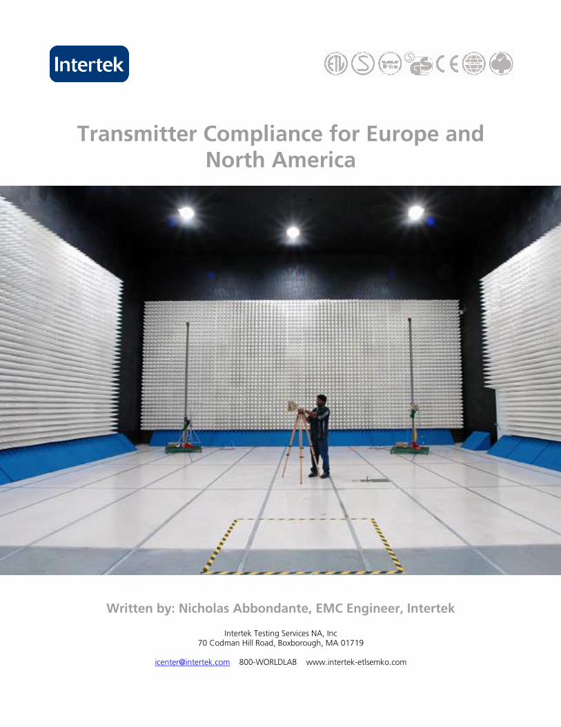
• Exemption Thresholds – depending on the operating frequency, harmful cell heating cannot occur below certain levels of RF power. Transmitters operating below these levels are commonly exempt from RF exposure evaluation, but the limits differ from one country to the next. Industry Canada RSS-102 clause 2.5 contains exemptions from routine evaluation for portable and mobile transmitters; EN 50371 in the EU exempts low-power devices below 20 mW average power density. (See photo below).
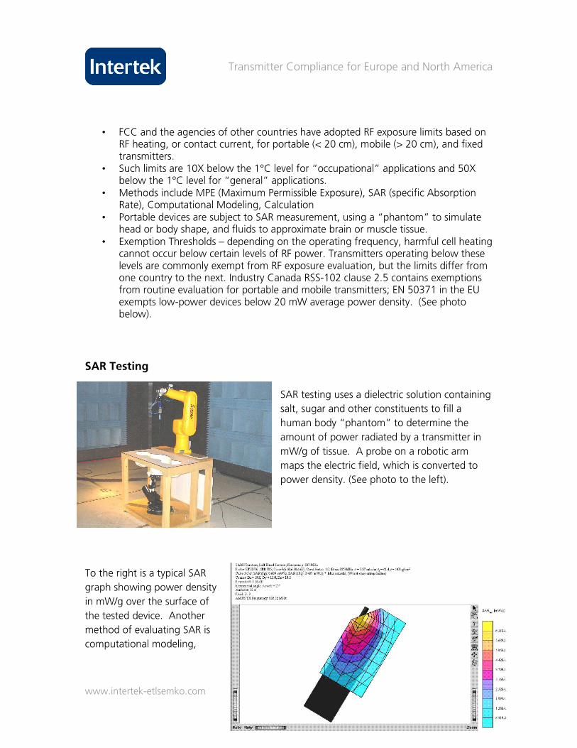
SAR Testing
SAR testing uses a dielectric solution containing
salt, sugar and other constituents to fill a
human body “phantom” to determine the
amount of power radiated by a transmitter in
mW/g of tissue. A probe on a robotic arm
maps the electric field, which is converted to
power density. (See photo to the left).
To the right is a typical SAR
graph showing power density
in mW/g over the surface of
the tested device. Another
method of evaluating SAR is
computational modeling,
Transmitter Compliance for Europe and North America
www.intertek-etlsemko.com 14
which uses software to simulate the SAR results. Calculation methods can be used for
mobile and fixed transmitters. In this method, field strength is calculated from antenna
port power and antenna gain.
MPE Evaluation, Calculation, Computation SAR measurement is appropriate in situations where the user and others will be closer than 20 cm to the transmitter and antenna, since this is generally within the “near field” where power density and therefore RF exposure are not easy to predict. Beyond 20 cm, RF fields become better-behaved so that analytical or computational approaches to evaluating RF exposure are realistic.
The computation of MPE is based on the uniform spherical distribution of the RF energy exiting the antenna port, corrected for the gain of the antenna. The sphere radius is chosen to be the nearest approach distance (“separation distance”) of users and others to the transmitter, but in no case less than 20 cm.
For example, assume that the RF power to the antenna is 1W (or 1,000 mW), and the separation distance is 20 cm. The power density on the surface of the 20 cm radius sphere will be 1W/(sphere area), or 1 W/(4π202). The calculation yields an MPE of 0.2 mW/cm2. Depending on the operating frequency, common MPE limits range from 0.2 to 1 mW/cm2. An antenna with a gain or directionality greater than 1 will increase MPE accordingly. MPE limits and restrictions are found in FCC 1.1310 and 2.1091, and in RSS-102.
Basic limits for RF exposure in the EU are found in Council Recommendation 1999/519/EC, and in the several harmonized EU standards for cellular handsets, base stations, RFID transmitters and similar.
Certification Documentation The documentation requirements for certification of devices in the U.S. and Canada are very similar, but the certification processes are separate and in each jurisdiction the test report must show compliance with the appropriate rules. It is acceptable for Industry Canada certification to submit an FCC test report plus a cross-reference demonstrating that the Industry Canada requirements have also been met. Exhibits submitted for certification to Industry Canada regulations are normally confidential, except for the parameters that must be reported in the Radio Equipment List (REL). Thus FCC procedures for confidentiality do not apply in Canada.
• Letter of agency • Attestations • Request for confidentiality
Transmitter Compliance for Europe and North America
www.intertek-etlsemko.com 15
• User’s manual • Label text/placement • Form 731 • Certification agreement (TCB/CB) • Test setup photos • Schematics • Block diagram • Parts list (licensed devices only) • Tune-up procedure (licensed devices only) • Operational description • Internal photos • External photos
For these certifications, all letters must be signed and on the applicant’s company letterhead. Short- (renewable 45-day) and permanent confidentiality may be obtained if the proper justification is provided. Applicants may submit a draft version of the user’s manual for approval. Block diagrams should show block frequencies as well as intermediate frequencies that exist between blocks. With regard to electronic files such as Microsoft Word documents, pdf files, jpgs, gifs, etc., many photos should be bundled together in a Word document for clarity. This method not only reduces the number of files submitted, but it actually reduces the total file size as well. We recommend a file size of less than 3 MB, though 4 MB is the maximum permitted. (For Industry Canada, only pdfs are acceptable.)
Emissions Designators Emissions designators are a compact way to summarize the way that a transmitter uses RF spectrum. A complete emissions designator will contain information on the amount of spectrum needed by a transmitter, the nature of the modulation and whether it is analogue or digital, the number of channels of information, and the type of information being transmitted. The format is uniform internationally, having been standardized by the International Telecommunications Union – Radio Sector (ITU-R).
• Adopted in national regulations: FCC 2.201 & 2.202, IC TRC-43
• Bandwidth—replace decimal with a character that corresponds to the units of the bandwidth, such as H (Hz), K (kHz), M (MHz), or G (GHz)
• First symbol—type of modulation
• Second symbol—number and type of channels
• Third symbol—type of data transmitted
• Examples: 2M50F7D (frequency modulated multichannel digital data), 3K75D3D (amplitude modulated single channel analogue data)

Transmitter Compliance for Europe and North America
www.intertek-etlsemko.com 16
Unique Antenna Connectors The range and apparent power of a radio transmitter can be increased by replacing its original antenna with a more directional one (that is, one with higher gain). The unauthorized switching of antennas on unlicensed devices could cause interference to licensed radio service. Thus, the FCC and Industry Canada regulate the extent to which antenna-swapping can be done on unlicensed radios.
• FCC requires unique antenna connectors for detachable antennas, per 15.203
• Common connectors such as BNC, SMA, and TNC are not permitted
• In 2000, the FCC tried to further restrict the allowed types, but it has since rescinded the ruling.
• MMCX, MCX, R-SMA, R-BNC, R-TNC, etc., may be used.
This rule was intended to help prevent parts of 15 devices from being used with any antenna other than the one that was sold with it. The FCC has gone back and forth on this rule. Over time, connectors that were once unique have become readily available. On May 22, 2000 (Public Notice DA 00-1087), the FCC issued a public notice that further restricts the types of antenna connectors that are considered unique. On September 28, 2000 (Public Notice DA 00-2225), the FCC rescinded this ruling and again allowed the use of MMCX, MCX, and reverse polarity SMA, BNC, and TNC connectors.
In Canada, RSS-Gen clause 7.1.4 places general restrictions on antenna types but does not specify allowable connector types.
In the EU, transmitter power limitations are generally given in terms of EIRP (Equivalent Isotropic Radiated Power) which takes into account the antenna gain.
Restricted Bands In order to protect existing licensed services in certain frequency bands, the FCC and Industry Canada have restricted certain bands of operation. Unlicensed transmitters are not allowed to operate intentionally within these bands. A secondary restriction on operation in these bands is that spurious emissions generated by a transmitter, which may normally be allowed to exceed the Class B digital device limits, must meet the Class B limits in the restricted bands, even at transmitter harmonics. A table of the FCC-restricted bands can be found in CFR47 Part 15.205. A table of the IC-restricted bands appears in section 2.7 Table 1 of RSS-210 Issue 6, September 2005. The two tables are not identical.
Transmitter Compliance for Europe and North America
www.intertek-etlsemko.com 17
Modular Approvals
• Modular approval. • Limited modular approval. • Non-modular approval. • EU—“plug-in radio device.” • Off-the-shelf devices (repackaged).
Modular approvals allow organizations to seek approval for a small transmitter module—essentially a standalone board that makes up your transmitter. Normally, organizations must perform a permissive change or even a new filing on a transmitter whenever they make a revision to the device containing the transmitter. Revisions include board re-spins, changes in components, or modifications to the chassis and cabling, among other things. Obtaining a modular approval for a transmitter allows organizations to avoid recertifying the transmitter for each revision. The module is considered a separate device that complies with the regulations on its own. Normal approvals are still required for changes to the module itself. Modular approvals may cost more initially, since they entail testing the transmitter board separately from the entire device, in addition to testing the entire device with the transmitter module in place. However, modular approvals can be more economical in the long run. In addition to avoiding recertification for every change, organizations may use the approved module in other devices without receiving transmitter approvals on the entire product. IC modular requirements follow the FCC requirements. In the EU, testing is allowed on the module as a “plug-in radio device.” Unmodified off-the-shelf devices, implemented as part of a rack or placed inside a chassis, can be used without transmitter approvals. In this case, the device’s labeling information must remain visible. The FCC and Industry Canada criteria for modular approval of unlicensed transmitters are clearly outlined:
• Must be a complete transmitter. • Must comply with RF exposure limits. • RF section must be shielded. • Modulation/Data inputs must be buffered. • Must comply with unique antenna connector requirement or have onboard antenna. • Must be tested with antenna. • Must have on-board power regulation. • Must be tested standalone.
Transmitter Compliance for Europe and North America
www.intertek-etlsemko.com 18
If the transmitter fails to meet one or more of these criteria, it can still be certified in the U.S. and Canada, but under a “Limited Modular Approval” (LMA). The LMA certification carries restrictions on where the module can be installed and on who must be responsible for the installation (it cannot be an end user). The LMA Grant or certificate holder remains responsible for providing the appropriate information to OEM installers, including correct markings and user information on devices containing the transmitter. The holder also is responsible for controlling the installation process on LMA devices to ensure the module is installed in a compliant manner.
Conclusion
In this paper, Intertek-ETL Semko provides an overview of the increasingly stringent approval processes for devices that include transmitters. We describe the regulatory environments in North America and in the EU. In addition, we give up-to-date perspectives on factors such as correct labeling and marking, the types of tests that different nations require, and the documentation that must support applications for certification.
Of course, it is not possible here to give a detailed breakdown of compliance requirements for every nation where your products may be sold. For more information, including specifics on other nations’ regulations or for more detail on test procedures in North America or Europe, contact Intertek-ETL Semko’s experts on transmitter compliance. With more than 322 laboratories in 110 countries around the world, 20 of them in the U.S. alone, Intertek provides the answers you need—within 24 hours.
For more information, go to www.intertek-etlsemko.com. You can also call 1-800-967-5352 or email [email protected]. We look forward to helping you.