Embed Size (px)
Citation preview

8/8/2019 Transmission Tech.
http://slidepdf.com/reader/full/transmission-tech 1/52
1
Communication Defined
8/8/2019 Transmission Tech.
http://slidepdf.com/reader/full/transmission-tech 2/52
2
Communication Defined
PRINCIPLES OF TRANSMISSION
History :
The purpose of telephony is to connect two correspondents, enabling them to conduct a conversation.
Bell was the first, in 1878, to use sound pressure variations on a diaphragm to obtaina corresponding electric current variation. This was the birth of telephonetransmission, a development which has subsequently seen explosive growth.
To achieve a good level of intelligible speech transmission, it is sufficient to use the300 3400 Hz frequency band (CCITT standard).
It quickly became essential to be able to transmit a number of telephoneconversations on the same carrier.
The notion of telephone channel multiplexing emerged from this need.

8/8/2019 Transmission Tech.
http://slidepdf.com/reader/full/transmission-tech 3/52
3
Communication Defined
Multiplexing :Channel multiplexing is essential for telephone transmission. This technique makes it possible to reduce, very substantially, the number of links required to connect thesubscribers.
1. Frequency Division Multiplexing (FDM)
2. Time Division Multiplexing (TDM)
Frequency Division Multiplexing (FDM) :This system is based on the juxtaposition of the different channels to be transmitted,in terms of frequency.
Each channel uses a maximum frequency band of 4kHz. The number of channelstransmitted is thus calculated by dividing the multiplexed frequency band by 4kHz.
This multiplexing mode makes it possible to obtain a high number of channels in arestricted bandwidth, but involves a number of disadvantages which tend to causerelatively rapid degradation of the data transmitted :
High sensitivity to external interference and
Aggregation and amplification of distortion up to the final destination.

8/8/2019 Transmission Tech.
http://slidepdf.com/reader/full/transmission-tech 4/52
4
1 2 n3 n-1
0 4kHz 8 kHz 12 kHz
Bandwidth used = n x 4 kHz
f
Communication Defined

8/8/2019 Transmission Tech.
http://slidepdf.com/reader/full/transmission-tech 5/52
5
Communication Defined
Time Division Multiplex (TDM) :
Principle :
The signal to be transmitted is fully defined by its instantaneous values sampled at regular intervals, subject to certain conditions (Shannon Theorem). It is therefore
possible to insert samples of n-1 other channels between two samples of aparticular channel, to constitute a Time Division Multiplex (TDM) frame of nchannels.
The sampling of the original voice signal is made at 8kHz,
Twice the maximum frequency in the signal being transmitted (300 Hz 3400 Hz).

8/8/2019 Transmission Tech.
http://slidepdf.com/reader/full/transmission-tech 6/52
6
1
2
n 1
2
n
Channel repetition (Te) Frame of n channels (Te)
Te Te
t
Communication Defined
8/8/2019 Transmission Tech.
http://slidepdf.com/reader/full/transmission-tech 7/52
7
Communication Defined
Three forms of modulation are possible :
Pulse Amplitude Modulation (PAM) :
The length of the sample is fixed, and amplitude varies according to modulation.
As in the case of FDM, this type of modulation is sensitive to thermal noise andcross talk.
Pulse Width Modulation (PWM) :
Pulse amplitude is fixed, but pulse length is variable. Variation follows the peakamplitude of the modulation transmitted.
This mode is less sensitive to noise than PAM, but is still far from ideal, as carrier-related phase distortion can nevertheless affect the signal.
Pulse Code Modulation (PCM) :The sample amplitude value is replaced by a binary word, comprising 0 and 1 bits, representing sample amplitude.
This modulation mode is practically insensitive to transmission environment perturbations.

8/8/2019 Transmission Tech.
http://slidepdf.com/reader/full/transmission-tech 8/52
8
Communication Defined
Choice of PCM mode :
The PCM mode, offering lowest sensitivity to external noise and interference, andrepresenting at the same time the most economic solution, was selected for digitaltelephone transmission.
Advantages of Digital Transmission :
Telephone channel TDM Digital Transmission offers a number of un questionableadvantages :
low sensitivity to propagation environment distortion;
High Signal to Noise (S/N) ratio;
Competitive price and high degree of reliability, resulting from progress inthe field of dedicated ICs and hybrid circuits;
Universal accessibility of the network, as any digital signal (e.g. data) ordigitized signal (telephone) can be transmitted.

8/8/2019 Transmission Tech.
http://slidepdf.com/reader/full/transmission-tech 9/52
9
Digital Technology

8/8/2019 Transmission Tech.
http://slidepdf.com/reader/full/transmission-tech 10/52
10
DIGITIZATION PRINCIPLE
?
M E-1LINE
TERMINAL
LINE
TERMINALM E-1
?BIN
2.048 M
BIN
32analog
channels
32analog
channels
HDB 3
HDB 3
Component elements of a low rate link
A low rate link multiplexes 32 telephone channels, giving a digital transmission rate of 2.048 Mbps.
This type of link has two basic elements :
These being the Primary Multiplexer (M E-1) and the Line Terminal Equipment (LTE).
The CCITT recommendations, designed to define standards common to all equipment,apply at Line Terminal junction level.

8/8/2019 Transmission Tech.
http://slidepdf.com/reader/full/transmission-tech 11/52
11
DIGITIZATION PRINCIPLE
The Primary Multiplexer (M E-1) provides the five basic ADC or DAC operations :
Sampling,
Quantification,
Compression,
Coding,
Time-division multiplexing.
The LTE provides the following three functions :
Junction between Multiplexer and telephone link,
Trans coding,
Junction and line testing.
8/8/2019 Transmission Tech.
http://slidepdf.com/reader/full/transmission-tech 12/52
12
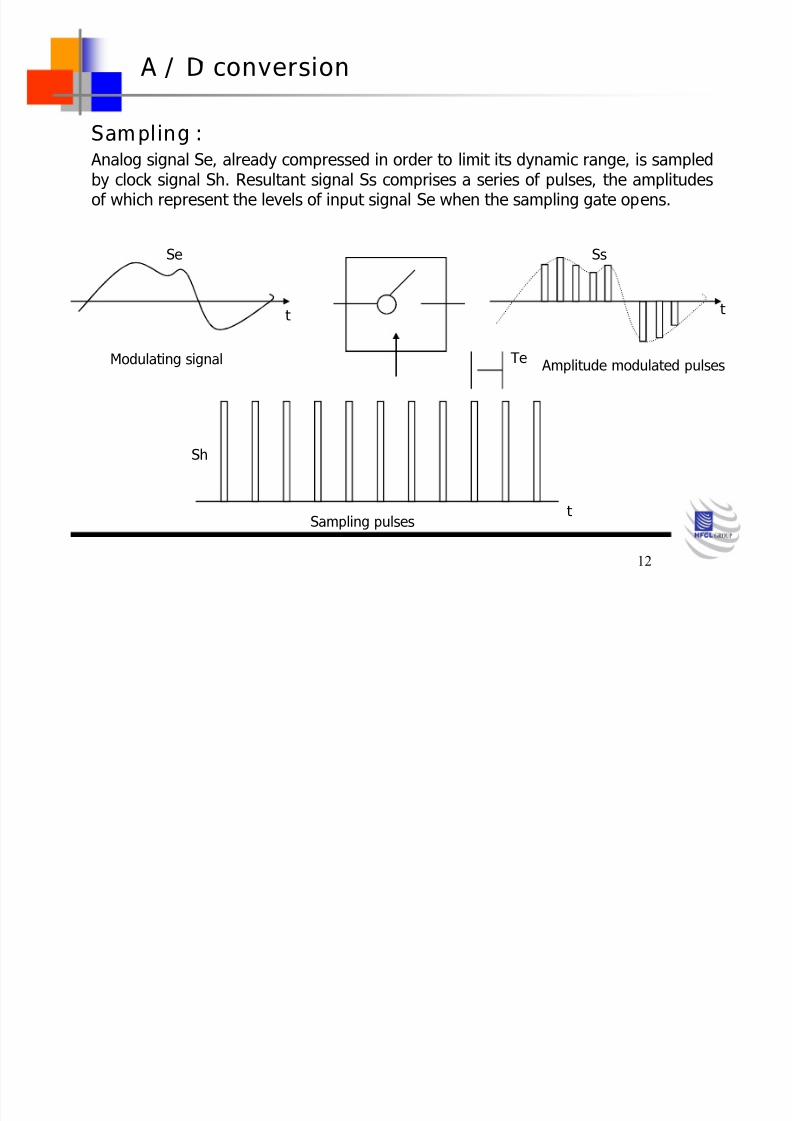
A / D conversion
Sampling : Analog signal Se, already compressed in order to limit its dynamic range, is sampledby clock signal Sh. Resultant signal Ss comprises a series of pulses, the amplitudesof which represent the levels of input signal Se when the sampling gate opens.
Sampling pulses
Te
SsSe
Modulating signal Amplitude modulated pulses
Sh
t
t t
8/8/2019 Transmission Tech.
http://slidepdf.com/reader/full/transmission-tech 13/52
13
A / D conversion
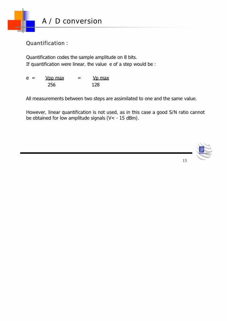
Quantification :
Quantification codes the sample amplitude on 8 bits.
If quantification were linear, the value e of a step would be :
e = Vpp max = Vp max256 128
All measurements between two steps are assimilated to one and the same value.
However, linear quantification is not used, as in this case a good S/N ratio cannot
be obtained for low amplitude signals (V< - 15 dBm).
8/8/2019 Transmission Tech.
http://slidepdf.com/reader/full/transmission-tech 14/52
14
A / D conversion
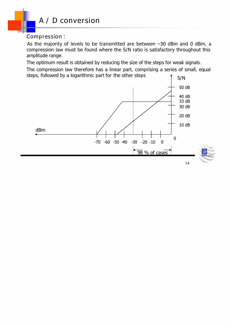
Compression :
As the majority of levels to be transmitted are between 30 dBm and 0 dBm, acompression law must be found where the S/N ratio is satisfactory throughout thisamplitude range.
The optimum result is obtained by reducing the size of the steps for weak signals.
The compression law therefore has a linear part, comprising a series of small, equalsteps, followed by a logarithmic part for the other steps
S/N
50 dB
40 dB
30 dB
20 dB
10 dB
0
33 dB
0-10-20-30-40-50-60-70
dBm
98 % of cases

8/8/2019 Transmission Tech.
http://slidepdf.com/reader/full/transmission-tech 15/52
15
A / D conversion
Coding :
When the signal has been quantified, the value of the steps which it occupies at thesampling times is transmitted in binary code form.
The coding law uses 12 straight line segments, each with 16 ranges (giving a total of 256 ranges). The ranges occupied are coded in 8-bit binary word form :
S A B C Y X W Z
Sign Segment Position in Segment
The first bit represents the sign of the input voltage, the next 3 bits the segment number, and the last 4 bits the range (1 to 16) in segment.
Various types of coder can be used :
single ramp, double ramp, quadruple ramp, series or parallel resistive type, with orwithout sampling memory.
8/8/2019 Transmission Tech.
http://slidepdf.com/reader/full/transmission-tech 16/52
16
A / D conversion
Multiplexing :
Time-division multiplexing juxtaposes bytes corresponding to sample measurementson channels 1 to 32, in time.
The signals from the different coders can be :
Synchronous :
Same frequency but with constant signal-to-signal phase shift; Quasi-Synchronous :
Signal-to-signal frequency very close but not identical.
Synchronous Signals:
The resultant multiplexed signal has a rate equivalent to the base rate 64 Kbps
( 64 Kbps = 8 kHz X 8 bits), multiplied by the number of channels multiplexed.Good synchronization between data received and data transmitted, is only obtainedby adding a frame sync byte.
The rate obtained then depends on the number of additional bytes added forsynchronization purposes, and to carry the signaling channels.

8/8/2019 Transmission Tech.
http://slidepdf.com/reader/full/transmission-tech 17/52
17
DIGITAL TRANSMISSION
Quasi-Synchronous Signals :
The frequency difference existing between the signals to be multiplexed makes it necessary for the Multiplexer to introduce additional, packing bits, to avoid excessivephase shift.
To be able to recognize these packing bits on reception, they must be situated at
clearly identified points in the frame, and presence of a packing bit or not, in thespecified position, must be indicated by justification bits.
In reality, clock frequencies are very close, allowing for oscillator tolerances and timestability.
The PCM Multiplexer input signals are therefore Quasi-Synchronous.
The CCITT standard basic transmission frame comprises 30 telephone channels + 2signaling channels, with a rate of 2.048 Mbps.

8/8/2019 Transmission Tech.
http://slidepdf.com/reader/full/transmission-tech 18/52
18
DIGITAL TRANSMISSION
Frames and Multi-frames : A first order frame comprises 30 telephone channels and 2 signaling channels.
A Time Slot (TS), numbered 0 to 31, is assigned to each telephone channel.
Each TS has 8 bits, numbered 1 to 8.
Signaling15 speech time slots 15 speech time slotsFrame sync
TS 0 TS16 TS31
Time slot TS0 is used for frame sync.
TS 16 caries signaling data
The other time slots are used for channel coding from 0 to 30Recognition of the frame sync word indicates that telephone channel No. 1 startsimmediately after this word.
When the receiver fails to recognize the frame sync word, it makes two furtherchecks before declaring sync loss.

8/8/2019 Transmission Tech.
http://slidepdf.com/reader/full/transmission-tech 19/52
19
DIGITAL TRANSMISSION
The sync loss criterion is therefore three consecutive missing Frame Sync Words (FSW).
Sync recovery criteria are determined by the presence of the frame sync word for twoconsecutive frames, to avoid synchronization on a time slot corresponding to atelephone channel.
A MULTIFRAME comprises a set of 16 frames, numbered 0 to 15.
Frame 0TS 16
Frame NTS 16
Frame 15TS 16
Multi frameSync
SignalingChannel N to N + 15
SignalingChannels 15 and 30

8/8/2019 Transmission Tech.
http://slidepdf.com/reader/full/transmission-tech 20/52
20
DIGITAL TRANSMISSION
Frame 0 is reserved for multi frame synchronization. Frame 1 to 15 are used to send signaling information concerning the 30
telephone channels on TS16 of each frame.
Multi frame sync loss conditions are therefore met for two consecutive absences of the multi frame sync word (MFS).
Synchronization is possible on recognition of a single MFS.
When a PCM system sync loss occurs, search for the frame sync word is followed bydetermination of the multi frame sync word.
The length of a 32 Time Slot frame is 125 µs.
The length of a multi frame containing 16 frames is 2 ms.
A sync word search interrupts speech for 2 ms.
This interruption being entirely imperceptible to users.
8/8/2019 Transmission Tech.
http://slidepdf.com/reader/full/transmission-tech 21/52
21
DIGITAL TRANSMISSION
Trans coding :
Trans coding converts binary information from the Multiplexer into other digital dataform, such that :
DC and LF signal components are eliminated, to allow remote repeater power
supply; A clock signal is transmitted, so that the regenerator repeaters can provide a
signal shaping function.
Various codes are used, according to selected rate :
AMI : Three-state bipolar RZ code,
HDB3 : Bi-polar code,CMI : Binary code.
The codes present at the line terminal junction sometimes differ from the line codesemployed.

8/8/2019 Transmission Tech.
http://slidepdf.com/reader/full/transmission-tech 22/52
22
DIGITAL TRANSMISSION
AMI CODE : Used for transmission at 2 and 8 Mbps, this code has the disadvantageof poor flexibility by comparison with the other codes.
HDB-3 CODE : Bipolar code providing for elimination of sequences of more than 4consecutive 0 states, by the addition of violation and packing bits.With its state redundancy, this code makes it possible to detect line
transmission errors. However, it is still necessary to determine HDB3violations on reception, violations appearing following a linetransmission error.
CMI CODE : Used for transmission at 140 Mbps,this is two level NRZ binary code,also designed for clock signal recovery, or at the reception end.
4B3T CODE : Used for transmission at 140 Mbps Line transmission, with threeternary signals corresponding to four binary signals (CMI). Theredundancy obtained then makes it possible to detect transmissionerrors, with a line rate (105 Mbps) less than junction rate (140 Mbps.

8/8/2019 Transmission Tech.
http://slidepdf.com/reader/full/transmission-tech 23/52
23
It offers to detect transmission errors by supervising the coding rules.1. RZ Code - A logic 1 is represented as half bit with a change of signal
levels from Low high Low.
Advantages : Clock retrieval possible also for adjacent Logic 1 bits.
Disadvantages : No information for zero sequences.
DC- Component on the stream.
2. AMI Code - ( Alternate Mark Inversion): The high state (logic1) isrepresented alternately as positive or negative signal level.
Advantages : Clock retrieval possible also for adjacent logic 1 bits.
No dc-component.Disadvantages : No clock information for zero sequences.
Interface Codes

8/8/2019 Transmission Tech.
http://slidepdf.com/reader/full/transmission-tech 24/52
24
3. HDB-3 Code - It is derived from the AMI code. Four consequent zero bits arereplaced by a 1001 or 0001 combination. This is done in such away that the signal receiver detects the mutilation of informational contents and cancels it.
Advantages : Maximum clock information.
No DC component.
Disadvantages : None
This coding is used from 2 M bit/s to 34 M bit/s Transmission signals.
4. CMI Code - Due to its easy generation with delay lines and simple gatefunctions the CMI code is suited especially for interfaces with
high bit rates. Therefore this code is standardized for the 140M bit/s and above.

8/8/2019 Transmission Tech.
http://slidepdf.com/reader/full/transmission-tech 25/52
25
V
CLOCK
NRZ BINARY DATA
RZ BINARY
AMI BIPOLAR
HDB-3 BIPOLAR
CMI BINARY

8/8/2019 Transmission Tech.
http://slidepdf.com/reader/full/transmission-tech 26/52
26
DIGITAL TRANSMISSION
HDB3 code : (high density bipolar code)
This code must comply with the following rules :
Bipolarity rule : 1 bits coded alternately + 1 and 1, with RZ in the next half-period.
When two successive 1 bits have the same polarity, this corresponds toviolation of the bipolarity rule.
There must not be more than 3 consecutive 0 bits. To achieve this, the 4th 0 bit is replaced by a 1 bit.
To detect this substitution, for deletion of the spurious 1 bit at the receptionend, it is sent in violation of the bipolarity rule (V), as shown below :
Binarycode
1 0 1 0 0 0 01 11 0 0 0 1
1 0
1
0 0 1 1 1 0 0 0 70 VHDB3code

8/8/2019 Transmission Tech.
http://slidepdf.com/reader/full/transmission-tech 27/52
27
DIGITAL TRANSMISSION
Successive violations must be of opposite polarity. If all violations in a
sequence of 0 bits have the same polarity, the mean value of the signalwould be non-zero.
When the number of 1 bits between two violations is not odd, a packingbit at 1 (P) is added in place of the first 0 bit.
Binarycode 1 0 0 0 0 0 01 1 0 0 0 0
1 0 0 0 V 1 1 P 0 0 0P VHDB3code
0 0
0 V
1
Recapitulating, if the number of 1 bits between a sequence of 0 bits andthe preceding violation is :
Odd, the sequence is coded : 0 0 0 V
Even, the sequence is coded : B 0 0 V
The HDB3 code shows slightly modified spectral distribution with respect to thebinary RZ code.

8/8/2019 Transmission Tech.
http://slidepdf.com/reader/full/transmission-tech 28/52
28
Digital Signal Hierarchies
397200 k bit/s
97728 k bit/s
32064 k bit/s 44736 k bit/s
274176 k bit/s
6312 k bit/s
1544 k bit/s
64 k bit/s
564992 k bit/s
139264 k bit/s
34368 k bit/s
8448 k bit/s
2048 k bit/s
Japan USA Europe
5. Level
4. Level
3. Level
2. Level
1. Level
Basic channel
x 24
x 4
x 5
x 3
x 4
x 6
x 7
x 4
x 4
x 4
x 4
x 30
*
*
*
* Frame structure not specified by CCITT REC.

8/8/2019 Transmission Tech.
http://slidepdf.com/reader/full/transmission-tech 29/52
29
Digital hierarchy Hierarchical bit rates (k bit/s for networks with the digitalhierarchy based on a first level bit rate of
1544 k bit/s 2 048 k bit/s
12
3
4
64
15446312
64
2 0488 448
34 368
139 26432 064
97 728
44 736
Digital Hierarchy Bit Rates
Current digital network are based on the plesiochronous hierarchies definedby CCITT rec. G. 702
Two set of bit rates exist:
- Based on a first level bit rate of 1544 k bit/s
- Based on a first level bit rate of 2048 k bit/s
DIGITAL TRANSMISSION
8/8/2019 Transmission Tech.
http://slidepdf.com/reader/full/transmission-tech 30/52
30
Transmission Hierarchy adopted in our country :
All hierarchic orders are standardized by CEPT & CCITT.
Standard digital rates are : 2.048 Mbps
8.448 Mbps34.368 Mbps
139.264 Mbps
Multiplexers are used to change from a lower order signal into a higher ordersignal.
DIGITAL TRANSMISSION NETWORK STRUCTURE
8/8/2019 Transmission Tech.
http://slidepdf.com/reader/full/transmission-tech 31/52
31
DIGITAL TRANSMISSION
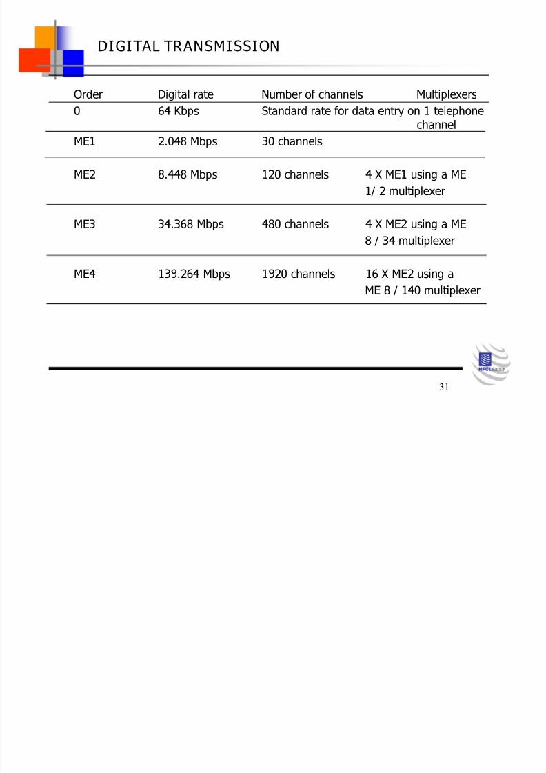
Order Digital rate Number of channels Multiplexers0 64 Kbps Standard rate for data entry on 1 telephone
channel
ME1 2.048 Mbps 30 channels
ME2 8.448 Mbps 120 channels 4 X ME1 using a ME
1/ 2 multiplexer
ME3 34.368 Mbps 480 channels 4 X ME2 using a ME
8 / 34 multiplexer
ME4 139.264 Mbps 1920 channels 16 X ME2 using a
ME 8 / 140 multiplexer
8/8/2019 Transmission Tech.
http://slidepdf.com/reader/full/transmission-tech 32/52
32
DIGITAL TRANSMISSION
The objective of increasing line channel capacity, combined with the appearance of new transmission carriers, have led equipment manufacturers to produce links withtransmission rates exceeding 140 Mbps.
This has resulted in the 560 Mbps rate, using simple 4 X 140 Mbps multiplexing.However, no junction as yet exists for this rate, and no corresponding
standardization has been undertaken so far.

8/8/2019 Transmission Tech.
http://slidepdf.com/reader/full/transmission-tech 33/52
33
DIGITAL TRANSMISSION
A high rate link is the result of a succession of PCM / ME multiplexing stages, serving toincrease :
digital transmission rate ;
link channel capacity.
PCM /ME-1
32 channels
ME-2
2 / 8
ME-38 / 34
*
ME-4
34 / 140
139.264
Mbps
34.368
Mbps
2.048 Mbps
8.448
Mbps4x ME-1
PCM /ME-1
2.048 Mbps
32 channels
High Rate Link.

8/8/2019 Transmission Tech.
http://slidepdf.com/reader/full/transmission-tech 34/52
34
DIGITAL TRANSMISSION
Digital transmission network : A digital network comprises a number of links, using different transmission rates(2-8-34-140 Mbps), according to the traffic volume to be handled.
TRANSMISSION CARRIERS : Various types of Digital Transmission Carrier are used today :
Co-axial cables, RF links, Satellites and Optical fiber.
Carriers are selected according to their suitability for specific problems, and on thebasis of economic considerations.
Coaxial cable :Coaxial cable characteristics are substantially better, than those for balanced paircable links. The attenuation of a coaxial pair, which increases as the square of
frequency, makes it necessary to insert repeaters at intervals along the link.The purpose of these repeaters being to regenerate the signal (amplification andshaping functions).
The coaxial cable is nevertheless an attractive solution for low digital transmissionrates.
8/8/2019 Transmission Tech.
http://slidepdf.com/reader/full/transmission-tech 35/52
35
DIGITAL TRANSMISSION
RF links :
This form of transmission uses centimeter wavelengths which can be concentrated invery narrow beams.
Propagation is limited to the optical horizon, and attenuation increases as the squareof distance (as compared with exponential attenuation in the case of a coaxial cable).
RF links therefore allow point-to-point transmission between a series of relay stationswhich are visible to each other, generally spaced at intervals of about 50 km.
The possibilities offered are very similar to those of coaxial cables, and the twotechniques are frequently both employed in the same long distance networks.
Equipment currently available provides for digital transmission at rates of 34Mbps, 2 X 34 Mbps and 140 Mbps.
8/8/2019 Transmission Tech.
http://slidepdf.com/reader/full/transmission-tech 36/52
36
Satellite :
A satellite telecommunications link can be considered as an extension of aconventional RF link.
A conventional link cannot be established between two continents. Due to thecurvature of the earth and the intervening expanse of ocean.
This transmission mode requires a geo stationary satellite, and a series of groundtransmitter and receiver stations.
The problems involved are considerable, but the enormous progress achieved in thisfield in the last few years, combined with the possibilities offered by this carriersystem.
This will lead to a substantial increase in the use of this method of communication.
8/8/2019 Transmission Tech.
http://slidepdf.com/reader/full/transmission-tech 37/52
37
DIGITAL TRANSMISSION
Optical fiber :
The most recent of the four forms of transmission carrier, the optical fiber uses light as the carrier for data transmission.
The light from a stable source (LASER) is propagated by a thin glass filament (CORE) coated with another material to avoid dispersion of the light.
The light is amplitude modulated to carry the digital transmission data. An avalanche photodiode is used at the receiver end.
Different types of fiber can be produced, according to core size and the value of core size and the value of core index n 1, and coating index n2 (n1 > n2):
mono mode fibers have a very small core (< 5 µm), giving a single longitudinalpropagation mode. This type of optical fiber gives best performance(attenuation of 0.2dB / km for a bandwidth of several tens of GHz / km,) but the price is high.
Multimode fibers, having a larger core size (30 to 80 µm), have a number of possible propagation modes. Multi modes fibers can be used for links withattenuation < 1.5 dB / km with bandwidth > 1 GHz / km.

8/8/2019 Transmission Tech.
http://slidepdf.com/reader/full/transmission-tech 38/52
38
DIGITAL TRANSMISSION
There are two types of multi modes fiber, one with constant core index (step indexfiber), and the other with a core index which decreases continuously from thecenter of the filament to the coating (index gradient fiber).
Optical fibers present numerous advantages over cables. These include:
Insensitivity to electromagnetic interference,
Absence of inter-channel cross talk,
Weight and space saving,
The possibility for simultaneous operation with a higher number of channels.
Fewer repeaters are also required.

8/8/2019 Transmission Tech.
http://slidepdf.com/reader/full/transmission-tech 39/52
39
COMMON BASIC FEATURES
Plesiochronous Digital Hierarchy (PDH) Multiplexing
- Pulse stuffing technique
- Tributary stream is transmitted without alteration of its timing clock
- The timing of the aggregate stream is different from the tributary one
- Lack of normalized auxiliary data (overhead)
8/8/2019 Transmission Tech.
http://slidepdf.com/reader/full/transmission-tech 40/52
40
The introduction of digital exchanges at the local and long distance levels was an
important step towards the digitization of the networks.
Over the course of time, different Plesiochronous Digital Hierarchies haveevolved based on different primary bit rates. All they have in common, is the single64 k bit/s channel.
Multiplex systems require a frame alignment signal to properly regenerate theframe synchronization in the receiver. A sequence of stuffing indicator bits are
used to manage the additional transmission capacity and ensure that clockdeviations do not result in bit slips.
Due to extra transmission capacity at each level the transparency needed for direct access to digital signals from lower level, hierarchy level is lost.
Since the introduction of Digital Transmission techniques, the aim has been todesign a hierarchy of digital transmission systems in which the clock frequencies of
various levels are synchronized to one other.
Although subscribers continue to be connected to the Local Exchange via Audio Frequency lines, extending digital network all the way to the subscriberpremises, ISDN can offer a no. of new services via the existing copper cablenetwork.
Highlights Of PDH Technology

8/8/2019 Transmission Tech.
http://slidepdf.com/reader/full/transmission-tech 41/52
41
ISDN is thus capable of integrating wide band services such as videotelephone, video conferencing and high speed transmission of documents anddata into its range of services.
The extension of the digital network all the way to the subscribers premises willalso involve wide band exchanges and transmission systems based on fiber opticalnetworks.
In the area of optical fiber transmission there are currently no generalstandards for higher bit rates and more versatile network structures.

8/8/2019 Transmission Tech.
http://slidepdf.com/reader/full/transmission-tech 42/52
42
when considering the evolution toward more flexible and intelligentstructures
Complexity of the frame structure
- With high capacity PDH systems the accessing of lower order tributaries is bothinflexible and costly
> To extract or insert a tributary it is necessary to perform all multiplexing-
de multiplexing operations on higher order streams.> As the network become more complex the tributaries access operations and
then the multiplex equipment and related costs increase (drop/insert)
Frame diversity for the different digital hierarchies level
Frame diversity for the two digital hierarchies (dual world standard)- interconnection of circuits between the two types of networks is expensive andinflexible.
Limitations of PDH Multiplexing

8/8/2019 Transmission Tech.
http://slidepdf.com/reader/full/transmission-tech 43/52
43
High cost of transporting non-hierarchical bit rates
- The transport of non-hierarchical bit rates tributaries is not possible without expensive adaptation. Many new services are being introduced will operate at bit rates different from those listed in the rec. G. 702.
- Necessity of a unique world standard
No standard above 140 Mbit/s- Fiber optic technology allows transmission of up 2.5 G bit/s at present and
much higher rates are envisaged in future.

8/8/2019 Transmission Tech.
http://slidepdf.com/reader/full/transmission-tech 44/52
44
The aim of the Synchronous Hierarchy is to provide a unified worldwidestandard. In addition, the ever-growing demand for wide band communicationslinks will be easier to satisfy.
Introduction of the SDH should significantly improve network management capabilities due to the expended overhead and more versatile multiplexertechnology.
An unified network node interface as specified in CCITT rec. G-708 eliminates thecompatibility problem between networks.
Besides a unified worldwide standard for transmission systems, SDH also offersimproved fault monitoring facilities.
Aim For New Technology

8/8/2019 Transmission Tech.
http://slidepdf.com/reader/full/transmission-tech 45/52
45
Creation of a world standard for bit rates above 140 M bit/s;
To enable Synchronous higher order Digital Multiplexing;
Normalization of auxiliary data (overhead);
More flexibility for networking;
Direct Access to tributaries;
To enable optical mid span meets;
Transport of both American and European PDH tributaries.
General SDH objectives

8/8/2019 Transmission Tech.
http://slidepdf.com/reader/full/transmission-tech 46/52
46
Advantages of Transmission Systems based on SDH Standardization of line optical interface
Standardization of frame format
Adoption of standardized auxiliary channels and control bit
Implementation of systems with flexible structure that can become part of newnetworks (LAN, MAN, B-ISDN)
- Automatic and centralized management of the Transmission Network
- New Network Topologies
- Integration of Terminals and Multiplexers
- New generation of Multiplexers, ADMs (Add-Drop Multiplexers)- Introduction of DXCs (Digital Cross-Connects)
- Lesser power consumption of the equipment
- Great flexibility for transporting non standard Tributaries.

8/8/2019 Transmission Tech.
http://slidepdf.com/reader/full/transmission-tech 47/52
47
In every node the incoming bit stream has to be synchronized to the local clock;
The jitter, wander and frequency differences generate activities of pointers to the VCcarried on output stream;
Pointers adjustment increases jitter of tributaries;
The synchronization network of the SDH nodes and jitter and wander of STM-Ndetermine pointer statistical activity, and transported tributaries;
SDH has been designed to work in a synchronized environment, however by means of pointer technique can face clock reference degradations and/or timing fluctuation of STM N.
SDH Synchronization

8/8/2019 Transmission Tech.
http://slidepdf.com/reader/full/transmission-tech 48/52
48
Classification of Optical Interfaces
Application Intra-office
Inter-office
Short-Haul Long-Haul
Source nominalwavelength(nm)
1310 1310 1550 1310 1550
Type of fiber Rec.G.652
Rec.G.652
Rec.G.652
Rec.G.652
Rec. G.652
Rec. G.654
Rec.G.653
Distance (km) * < 2 < 15 < 40 < 60
STM
level
STM-1 I-1 S-1.1 S-1.2 L-1.1 L-1.2 L-1.3
STM-4 I-4 S-4.1 S-4.2 L-4.1 L-4.2 L-4.3
STM-16 I-16 S-16.1 S-16.2 L-16.1 L-16.2 L-16.3
* These distances are used for classification and not for specification.

8/8/2019 Transmission Tech.
http://slidepdf.com/reader/full/transmission-tech 49/52
49
Application Categories :
- Intra-office: For distances less than 2km;
- Short-haul inter office: For distances of 15km;
- Long-haul inter-office: For distances of 40km at 1310nm wavelength
and 60km at 1550nm.
Application Code :- Takes the form
> Application STM Level suffix number
> Suffix number
Blank or 1 : Nominal 1310 nm wavelength sources on G.652 fiber;
2 : Nominal 1550 nm wavelength sources on G.652 fiber forshort- haul applications and either G. 652 or G. 654 fiber for
long-haul applications; 3 : Nominal 1550 nm wavelength sources on G. 653 fiber.
Classification of Optical Interfaces

8/8/2019 Transmission Tech.
http://slidepdf.com/reader/full/transmission-tech 50/52
50
G. 707 Synchronous Digital Hierarchy Bit Rate :
- Recommends that
- he first level of the SDH shall be 155 520 k bit/s
- Higher SDH bit rates shall be obtained as integer multiples of the first level bit rate
- Higher SDH levels should be denoted by the corresponding multiplication factorof the first level rate.
- The following bit rates should constitute the synchronous digital hierarchy.
Synchronous Digital Hierarchy level Hierarchical bit rates k bit/s
1 155 520
4 622 080
16 2 448 320
CCITT recommendations on SDH

8/8/2019 Transmission Tech.
http://slidepdf.com/reader/full/transmission-tech 51/52
51
G. 708 Network Node Interface for the Synchronous Digital Hierarchy.
- Recommends the frame structure for multiplexed digital signals at the NNI of a synchronous digital network including ISDN;
G. 709 Synchronous Multiplexing Structure
- Recommends the formats for multiplexing and mapping elements into theSTM-N at the NNI;
G. 781 Structure of recommendations on multiplexing equipment for theSynchronous Digital Hierarchy;
G. 782 Types and general characteristics of Synchronous Digital HierarchyMultiplexing Equipment.
- Gives general characteristics for SDH multiplexing equipment;
G. 783 Characteristics of Synchronous Digital Hierarchy MultiplexingEquipment functional blocks
- Describes interfaces and functions to be supported by equipment;
CCITT recommendations on SDH

8/8/2019 Transmission Tech.
http://slidepdf.com/reader/full/transmission-tech 52/52
52
G. 784 Synchronous Digital Hierarchy management :- Organization of the management of equipment.
G.803 Architectures of Transport Networks
- Based on the synchronous digital hierarchy (SDH);
G. 825 The Control of Jitter and Wander within digital networks
- Which are based on the Synchronous Digital Hierarchy (SDH);
G. 831 Management Capabilities of Transport Networks
- based on the Synchronous Digital Hierarchy (SDH);
G.957 Optical Interfaces for Equipment and systems relating to the SDH
- Recommends optical interface parameters specifications for equipment andsystems supporting the SDH and operating on single-mode optical fibersconforming to Rec.s G.652, G.53 and G.654;
G. 958 Digital Line Systems based on the SDH for use on Optical fiber cable
- Lists the requirements for digital Synchronous line systems.
CCITT recommendations on SDH