Embed Size (px)
DESCRIPTION
This document is a discussion about capacitance calculation of transmission lines.
Citation preview

CAPACITANCETRANSMISSION LINE PARAMETERS: A REVIEW

Definition
Transmission line conductors exhibit capacitance with respect to each other due to the potential difference between them.
The amount of capacitance between conductors is a function of the conductor size, spacing and height above ground.
Capacitance is the ratio of charge Q to the potential difference V.
Farad V
QC

Basic Principles
The electric field intensity at a point P due to an infinite line charge is:
The potential difference between two points due to a line charge is:
m
V
2 0
aE L
V ln2 1
21
2
12
o
LdLEV

Capacitance of 1-phase, 2-wire Transmission Lines
Assuming conductor 1 alone to have a charge of ρL1, the voltage between conductors 1 and 2 is:
Dr1 r2
V ln2
112 1 r
DV
o
LL

Capacitance of 1-phase, 2-wire Transmission Lines
Assuming conductor 2 having a charge of ρL2, the voltage between conductors 1 and 2 is:
Dr1 r2
V ln2
212 2 D
rV
o
LL

Capacitance of 1-phase, 2-wire Transmission Lines
Dr1 r2
12
21 0
LL
LL

Capacitance of 1-phase, 2-wire Transmission Lines
Dr1 r2
V ln2
V ln2
1
112 2
r
D
D
rV
o
L
o
LL

Capacitance of 1-phase, 2-wire Transmission Lines
By the Principle of Superposition,
r
DV
VVV
L
LL
ln0
112
121212 21

Capacitance of 1-phase, 2-wire Transmission Lines
The capacitance between conductors is:
Dr1 r2
m
F
ln
0
12
112
rDV
C L

Capacitance of 1-phase, 2-wire Transmission Lines
The capacitance between conductor to neutral is:
m
F
ln
2 0
rD
Cn

Potential Difference in a Multiconductor Configuration
By Superposition,
For i = m or k = m,
km
imM
mLmki
kM
iMLM
k
iL
k
iLki
D
DV
D
D
D
D
D
DV
ln2
1
ln2
...
...ln2
ln2
10
0
2
2
0
2
1
1
0
1
kkk
iii
rD
rD

Capacitance of Transposed 3-Phase Lines
1223
D31
1
2
3
2
3
1
1
12
23
3
I II III

Capacitance of Transposed 3-Phase Lines
Section I:
2
3
1
1
12
23
3
I II III
13
233
122
211
012
ln
lnln
2
1
D
D
D
r
r
D
V
L
LL
I

Capacitance of Transposed 3-Phase Lines
Section II:
2
3
1
1
12
23
3
I II III
12
133
232
231
012
ln
lnln
2
1
D
D
D
r
r
D
V
L
LL
II
Capacitance of Transposed 3-Phase Lines
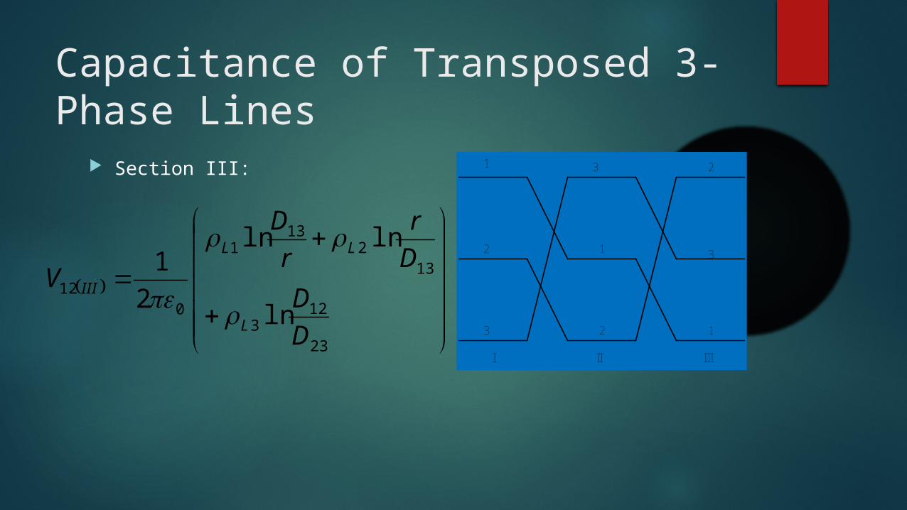
Section III:
2
3
1
1
12
23
3
I II III
23
123
132
131
012
ln
lnln
2
1
D
D
D
r
r
D
V
L
LL
III

Capacitance of Transposed 3-Phase Lines
The average value of V12 is:
GMD
r
r
GMDV
DDD
r
r
DDDV
DDD
DDD
DDD
r
r
DDD
V
LL
LL
L
LL
lnln2
1
lnln2
1
ln
lnln
23
1
210
12
3
1
132312
2
3
1
1323121
012
132312
1323123
132312
3
23132312
1
012

Capacitance of Transposed 3-Phase Lines
Similarly, the average value of V13 is:
GMD
r
r
GMDV LL lnln
2
131
013

Capacitance of Transposed 3-Phase Lines
Adding V12 and V13
But,
GMD
r
r
GMDVV LLL lnln2
2
1321
01312
132
321 0
LLL
LLL

Capacitance of Transposed 3-Phase Lines
r
GMDV
r
GMDV
r
GMDVV
GMD
r
r
GMDVV
Ln
Ln
L
LL
ln2
ln2
33
ln2
3
lnln22
1
0
11
0
11
0
11312
110
1312

Capacitance of Transposed 3-Phase Lines
The capacitance to neutral, Cn is:
m
F
ln
2 0
rGMD
Cn

Effect of Bundling on Capacitance
The effect of bundling is to introduce an equivalent radius rb.
The equivalent rb is similar to the GMR calculated for inductance with the exception that radius r of each subconductor is used instead of r’ or Ds.
The capacitance per phase (or line-to-neutral) is found to be
F/m ln
2 0
b
n
r
GMDC

Capacitance of Three-phase, Double-Circuit Lines
The capacitance per phase is found to be
Important: The expression for GMD is the same as was found for inductance
calculation.
The GMRCeq of each phase is similar to the GMRLeq with the exception that rb is used instead of Dbs.
F/m ln
2 0
Ceq
eqn
GMR
GMDC

Examples
1. A completely transposed 60-Hz three-phase line has flat horizontal phase spacing with 10 m between adjacent conductors. The conductors are Dove ACSR. Line length is 200 km. Determine the capacitance per phase and susceptance.

Solution to Example 1
D D
1 2 3
mho 10 6013.0F 595.1602fC2
phaseper F 595.1200000
01177.0599.12
ln
2
m 01177.0cm 100
m 1
1"
cm 54.2
2
"927.0
m 599.12201010
3-
0
3
C
r
GMD

Examples
2. A three-phase double circuit line is composed of 300,000 cmil, 26/7 Ostrich conductors arranged as shown in the figure below. Find the 60-Hz capacitive susceptance in ohms per mile per phase.

Solution to Ex. 2
ft 9072.261820
ft 9146.21
5.1910
ft 112.10
5.110
22''
22''''
22''''
ccaa
cbbcbaab
cbbcbaab
DD
DDDD
DDDD

Solution to Ex. 2
ft 14.16
ft 9737.18
ft 886.14
ft 886.14
3
4''''
4''''
4''''
CABCABeq
acaccacaCA
cbcbbcbcBC
babaababAB
GMDGMDGMDGMD
DDDDGMD
DDDDGMD
DDDDGMD

Solution to Ex. 2
ft 8165.0
ft 8731.0
ft 7141.0
ft 8731.0
ft 02833.012
1
2
"680.0
3
4 2'
2
4 2'
2
4 2'
2
cCcBcAceq
ccostrcC
bbostrcB
aaostrcA
ostr
GMRGMRGMRGMR
DrGMR
DrGMR
DrGMR
r

Solution to Ex. 2
Siemenor mho 10 01131.0F 03.0602fC2
phaseper F 03.01609
8165.014.16
ln
2
3-
0
nC

Effect of Earth on the Capacitance
The effect of earth is to increase the capacitance.
However, the height of the conductor is large compared to the distance between conductors and the earth effect is negligible.
Therefore, for all line models used for balanced steady-state analysis, the effect of earth on the capacitance can be neglected. But, for unbalanced analysis such as unbalanced faults, the earth’s effect as well as the shield wires should be considered.

Effect of Earth on the Capacitance
F/m
lnln
2
3321
3312312
0
HHH
HHH
r
GMDCn