Embed Size (px)
Citation preview
Transmission Availability Data Systems Frequently Asked Questions
March 2016
NERC | Report Title | Report Date I
Table of Contents
Preface ....................................................................................................................................................................... iii
Executive Summary ................................................................................................................................................... iv
Chapter 1 – TADS Inventory Related Questions .........................................................................................................1
Chapter 2 – Outage Related Questions ......................................................................................................................4
Chapter 3 – Event Related Questions .........................................................................................................................6
Chapter 4 – Inventory Configurations with Reporting Examples ...............................................................................7
Chapter 5 – Reporting changes and Portal issues ................................................................................................... 15
NERC | TADS Frequently Asked Questions | March 2016 ii

Preface The North American Electric Reliability Corporation (NERC) is a not-for-profit international regulatory authority whose mission is to assure the reliability of the bulk power system (BPS) in North America. NERC develops and enforces Reliability Standards; annually assesses seasonal and long-term reliability; monitors the BPS through system awareness; and educates, trains, and certifies industry personnel. NERC’s area of responsibility spans the continental United States, Canada, and the northern portion of Baja California, Mexico. NERC is the electric reliability organization (ERO) for North America, subject to oversight by the Federal Energy Regulatory Commission (FERC) and governmental authorities in Canada. NERC’s jurisdiction includes users, owners, and operators of the BPS, which serves more than 334 million people. The North American BPS is divided into several assessment areas within the eight Regional Entity (RE) boundaries, as shown in the map and corresponding table below.
The North American BPS is divided into eight Regional Entity (RE) boundaries. The highlighted areas denote overlap as some load-serving entities participate in one Region while associated transmission owners/operators participate in another.
FRCC Florida Reliability Coordinating Council
MRO Midwest Reliability Organization
NPCC Northeast Power Coordinating Council RF ReliabilityFirst
SERC SERC Reliability Corporation
SPP RE Southwest Power Pool Regional Entity Texas RE Texas Reliability Entity
WECC Western Electricity Coordinating Council
NERC | TADS Frequently Asked Questions | March 2016 iii
Executive Summary The purpose of this document is to provide a record of answers to questions that NERC staff has received on the NERC Transmission Availability Data System (TADS).
NERC | TADS Frequently Asked Questions | March 2016 iv
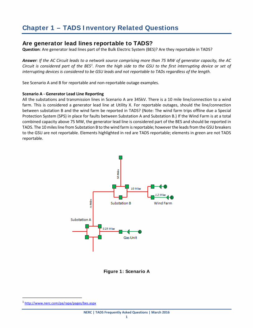
Chapter 1 – TADS Inventory Related Questions Are generator lead lines reportable to TADS? Question: Are generator lead lines part of the Bulk Electric System (BES)? Are they reportable in TADS? Answer: If the AC Circuit leads to a network source comprising more than 75 MW of generator capacity, the AC Circuit is considered part of the BES1. From the high side to the GSU to the first interrupting device or set of interrupting devices is considered to be GSU leads and not reportable to TADs regardless of the length. See Scenario A and B for reportable and non-reportable outage examples. Scenario A - Generator Lead Line Reporting All the substations and transmission lines in Scenario A are 345kV. There is a 10 mile line/connection to a wind farm. This is considered a generator lead line at Utility X. For reportable outages, should the line/connection between substation B and the wind farm be reported in TADS? (Note: The wind farm trips offline due a Special Protection System (SPS) in place for faults between Substation A and Substation B.) If the Wind Farm is at a total combined capacity above 75 MW, the generator lead line is considered part of the BES and should be reported in TADS. The 10 miles line from Substation B to the wind farm is reportable; however the leads from the GSU breakers to the GSU are not reportable. Elements highlighted in red are TADS reportable; elements in green are not TADS reportable.
Figure 1: Scenario A
1 http://www.nerc.com/pa/rapa/pages/bes.aspx
NERC | TADS Frequently Asked Questions | March 2016 1
Chapter 1 – TADS Inventory Related Questions
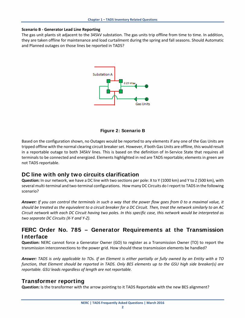
Scenario B - Generator Lead Line Reporting The gas unit plants sit adjacent to the 345kV substation. The gas units trip offline from time to time. In addition, they are taken offline for maintenance and load curtailment during the spring and fall seasons. Should Automatic and Planned outages on those lines be reported in TADS?
Figure 2: Scenario B
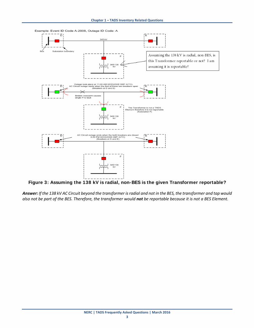
Based on the configuration shown, no Outages would be reported to any elements if any one of the Gas Units are tripped offline with the normal clearing circuit breaker set. However, if both Gas Units are offline, this would result in a reportable outage to both 345kV lines. This is based on the definition of In-Service State that requires all terminals to be connected and energized. Elements highlighted in red are TADS reportable; elements in green are not TADS reportable. DC line with only two circuits clarification Question: In our network, we have a DC line with two sections per pole: X to Y (1000 km) and Y to Z (500 km), with several multi-terminal and two-terminal configurations. How many DC Circuits do I report to TADS in the following scenario? Answer: If you can control the terminals in such a way that the power flow goes from 0 to a maximal value, it should be treated as the equivalent to a circuit breaker for a DC Circuit. Then, treat the network similarly to an AC Circuit network with each DC Circuit having two poles. In this specific case, this network would be interpreted as two separate DC Circuits (X-Y and Y-Z). FERC Order No. 785 – Generator Requirements at the Transmission Interface Question: NERC cannot force a Generator Owner (GO) to register as a Transmission Owner (TO) to report the transmission interconnections to the power grid. How should these transmission elements be handled? Answer: TADS is only applicable to TOs. If an Element is either partially or fully owned by an Entity with a TO function, that Element should be reported in TADS. Only BES elements up to the GSU high side breaker(s) are reportable. GSU leads regardless of length are not reportable. Transformer reporting Question: Is the transformer with the arrow pointing to it TADS Reportable with the new BES alignment?
NERC | TADS Frequently Asked Questions | March 2016 2
Chapter 1 – TADS Inventory Related Questions
Figure 3: Assuming the 138 kV is radial, non-BES is the given Transformer reportable?
Answer: If the 138 kV AC Circuit beyond the transformer is radial and not in the BES, the transformer and tap would also not be part of the BES. Therefore, the transformer would not be reportable because it is not a BES Element.
NERC | TADS Frequently Asked Questions | March 2016 3

Chapter 2 – Outage Related Questions What is the Sustained Cause Code when lightning causes a line to trip and the line fails to auto-reclose as designed, causing the line to remain out for 10 minutes? Question: Lightning causes a line to trip and the line fails to auto-reclose as designed, causing the line to remain out for 10 minutes. Should the sustained cause be Lightning or Failed Protection System Equipment? In the past, a recloser was considered part of the Protection System. However, with the new Protection System2 definition, the recloser is no longer considered part of the Protection System. How do I report the Sustained Cause Code when a line fails to reclose? Answer: In this case, according to the TADS Data Reporting Instruction3 (DRI) manual apply the Sustained Cause Code that “contributed to the longest duration of the Outage”. The recloser failing is the cause contributing the longest duration. Based on the AC Circuit boundary, the recloser could be considered within either the AC Circuit or AC Substation. It could be either Failed AC Circuit Equipment or Failed AC Substation Equipment based on the recloser’s location. Trees washed out during flooding, slid down hill, and contacted line. Is the cause environmental or vegetation? Question: Trees washed out during flooding, slid down hill, and contacted line. Is the initiating cause code environmental or vegetation? Answer: The initiating cause code would be environmental due to the flood. Momentary, Less than One Minute Operational Outage Question: We had a momentary outage on a transmission line (fifth on that line that day) because of buzzard “pollution”. Fifty seconds later, the dispatchers manually opened the line (Emergency Forced) and the line remained deenergized for a week. How should we report these outages? One (automatic) or two (automatic and manual)? Answer: The outage should be reported as a single Outage due to the buzzard “pollution”. In this case, it would be one Automatic Outage. The AC Circuit must be energized and connected at all terminals for at least one minute to be considered back in an In-Service state. This clause avoids numerous entries of auto-reclosing Automatic Outages. Operator Turns the Wrong Handle Question: The operator was switching out a breaker and turned the wrong handle? Answer: For 2015, an Operational Cause Code called “Human Error” was added to specifically address this situation. Therefore, the outage would be reported as a non-automatic, operational outage. It is NOT automatic, as the operator in Question: manually opened the wrong breaker. It's clearly a Manual operation. (The same argument could be made for test personnel who are intentionally 'tripping' a relay, but unintentionally open a breaker. The operation was NOT automatic.)
2 An Automatic Outage of an Element that is initiated on or within the Protection System. 3 http://www.nerc.com/pa/RAPA/tads/Pages/default.aspx
NERC | TADS Frequently Asked Questions | March 2016 4
Chapter 2 – Outage Related Questions
Operator closes the second end of the line back after more than one minute Question: A line correctly trips, and correctly recloses from one end. The other end of the line is designed to not reclose. If the operator closes the second end of the line back after more than one minute, what is the “Sustained Code”? There is no damage to the line, and the operator did not make an error. In the past, I was advised that this would be the same as the Outage Initiating Code. Is this correct? Answer: If one or more terminals are not designed to reclose or reclosing has been disabled for any condition, then the sustained cause code would be other. Sustained Cause Code for a line that correctly trips but fails to reclose on one end due to a reclosing relay failure. Question: A line correctly trips but fails to reclose on one end due to a reclosing relay failure. What is the “Sustained Code”? Reclosing is no longer part of the NERC Glossary definition of Protection System. Answer: Depending on whether the recloser is contained within the AC Circuit or AC Substation, the Sustained Cause Code would be either Failed AC Circuit Equipment or Failed AC Substation Equipment. How to code an outage when a circuit is out of service for scheduled maintenance all day and was accidentally energized and closed/tripped. Question: We had a circuit out of service for scheduled maintenance all day and it was inadvertently energized and the breaker closed, then automatically tripped. Should be entered in TADS as a momentary outage. Answer: For TADS, an AC Circuit must remain in an In-Service State for at least one minute for the Outage to be counted as a separate Outage. In this case, there would not be a second Outage because the closing/tripping occurred during an already occurring Planned Outage.
NERC | TADS Frequently Asked Questions | March 2016 5

Chapter 3 – Event Related Questions Clarification of “Normal Clearing” Question: Clarification of “Normal Clearing”: If a breaker fails to trip from primary relaying but does successfully trip in the required time via secondary/backup relaying, is this considered normal or abnormal? Answer: This is considered abnormal clearing according to the definitions. The outage should be coded with Event Type 61 (Dependability based). If a breaker trips for lightning and doesn't reclose because of an issue reclosing, this is NOT abnormal clearing. Is this correct? Question: If a breaker trips due to lightning and doesn't reclose because of a reclosing problem, is this considered normal clearing or abnormal clearing? Answer: For TADS, once the breaker correctly trips, it is normal clearing. Normal clearing and abnormal clearing are only concerned with protection trips, intended (correct) or unintended (incorrect) clearing of an Element. It has nothing to do with reclosing functions. Normal vs. Abnormal Clearing depending on normal clearing circuit breaker set. Question: If a system is set up to clear more than one line during a fault (and this is the expected result) even though it is not normally set up this way (issue with breaker so two lines are being protected by single breaker), this would be normal clearing as well? Answer: By manually changing whether the breaker is bypassed or not, the TO has indicated that it has changed its normal clearing circuit breaker set. However, if the second AC Circuit cleared due to the primary protection failing or the backup protection overreaching, the Event would be abnormal clearing.
NERC | TADS Frequently Asked Questions | March 2016 6
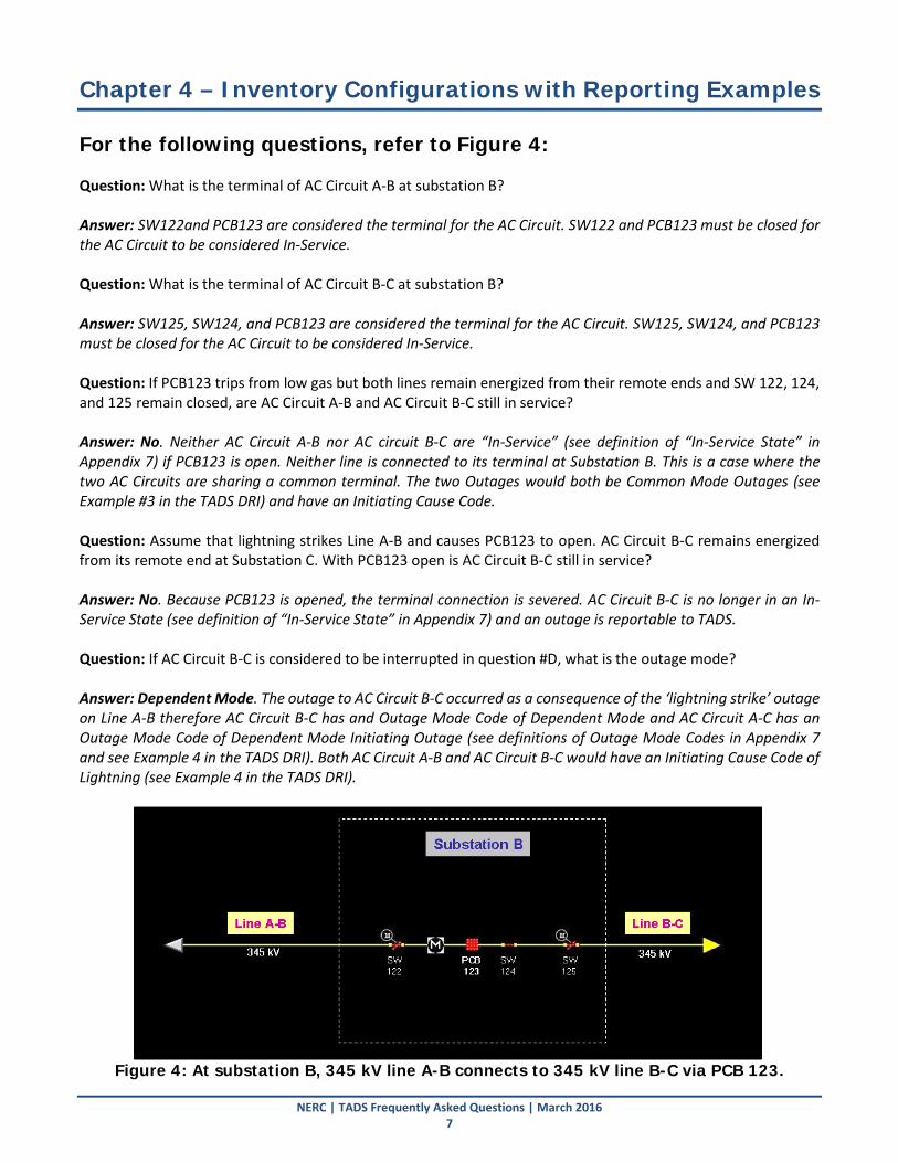
Chapter 4 – Inventory Configurations with Reporting Examples For the following questions, refer to Figure 4: Question: What is the terminal of AC Circuit A-B at substation B? Answer: SW122and PCB123 are considered the terminal for the AC Circuit. SW122 and PCB123 must be closed for the AC Circuit to be considered In-Service. Question: What is the terminal of AC Circuit B-C at substation B? Answer: SW125, SW124, and PCB123 are considered the terminal for the AC Circuit. SW125, SW124, and PCB123 must be closed for the AC Circuit to be considered In-Service. Question: If PCB123 trips from low gas but both lines remain energized from their remote ends and SW 122, 124, and 125 remain closed, are AC Circuit A-B and AC Circuit B-C still in service? Answer: No. Neither AC Circuit A-B nor AC circuit B-C are “In-Service” (see definition of “In-Service State” in Appendix 7) if PCB123 is open. Neither line is connected to its terminal at Substation B. This is a case where the two AC Circuits are sharing a common terminal. The two Outages would both be Common Mode Outages (see Example #3 in the TADS DRI) and have an Initiating Cause Code. Question: Assume that lightning strikes Line A-B and causes PCB123 to open. AC Circuit B-C remains energized from its remote end at Substation C. With PCB123 open is AC Circuit B-C still in service? Answer: No. Because PCB123 is opened, the terminal connection is severed. AC Circuit B-C is no longer in an In-Service State (see definition of “In-Service State” in Appendix 7) and an outage is reportable to TADS. Question: If AC Circuit B-C is considered to be interrupted in question #D, what is the outage mode? Answer: Dependent Mode. The outage to AC Circuit B-C occurred as a consequence of the ‘lightning strike’ outage on Line A-B therefore AC Circuit B-C has and Outage Mode Code of Dependent Mode and AC Circuit A-C has an Outage Mode Code of Dependent Mode Initiating Outage (see definitions of Outage Mode Codes in Appendix 7 and see Example 4 in the TADS DRI). Both AC Circuit A-B and AC Circuit B-C would have an Initiating Cause Code of Lightning (see Example 4 in the TADS DRI).
Figure 4: At substation B, 345 kV line A-B connects to 345 kV line B-C via PCB 123.
NERC | TADS Frequently Asked Questions | March 2016 7
Chapter 4 – Inventory Configurations with Reporting Examples
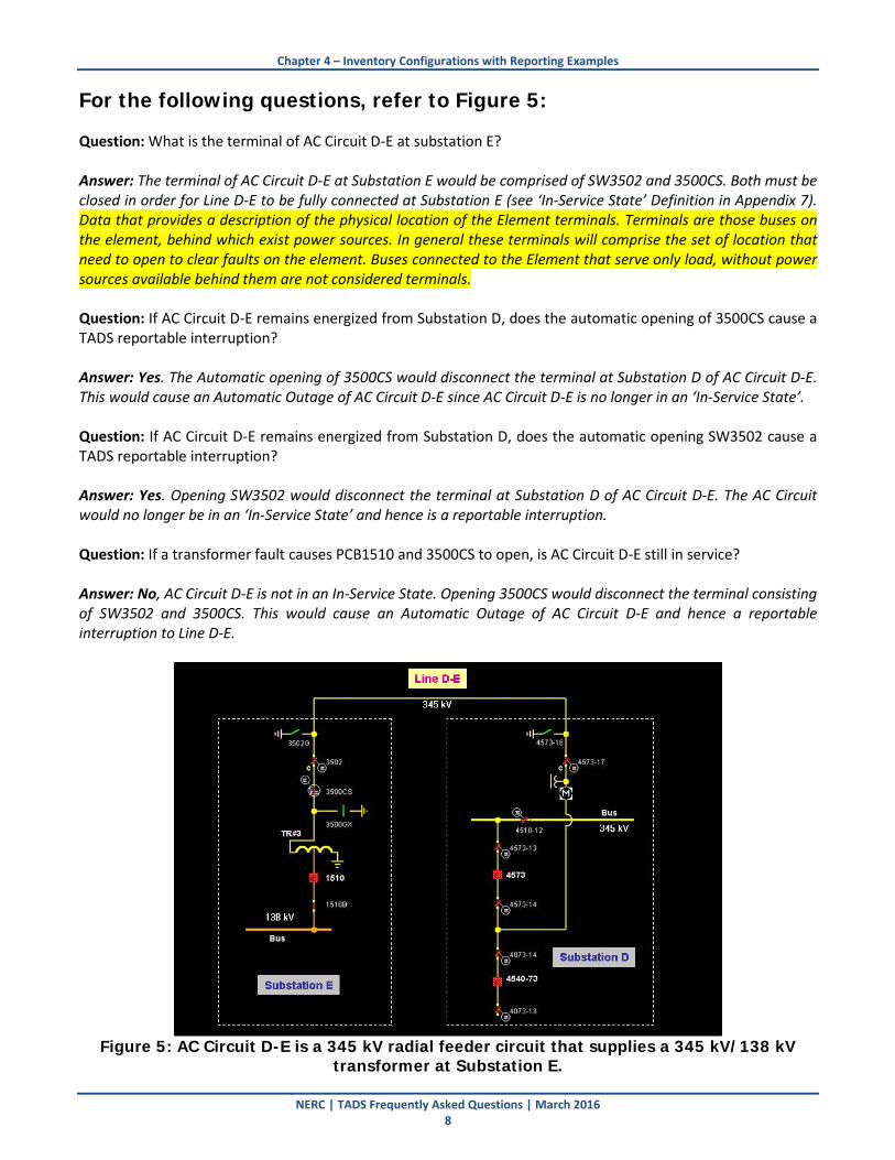
For the following questions, refer to Figure 5: Question: What is the terminal of AC Circuit D-E at substation E? Answer: The terminal of AC Circuit D-E at Substation E would be comprised of SW3502 and 3500CS. Both must be closed in order for Line D-E to be fully connected at Substation E (see ‘In-Service State’ Definition in Appendix 7). Data that provides a description of the physical location of the Element terminals. Terminals are those buses on the element, behind which exist power sources. In general these terminals will comprise the set of location that need to open to clear faults on the element. Buses connected to the Element that serve only load, without power sources available behind them are not considered terminals. Question: If AC Circuit D-E remains energized from Substation D, does the automatic opening of 3500CS cause a TADS reportable interruption? Answer: Yes. The Automatic opening of 3500CS would disconnect the terminal at Substation D of AC Circuit D-E. This would cause an Automatic Outage of AC Circuit D-E since AC Circuit D-E is no longer in an ‘In-Service State’. Question: If AC Circuit D-E remains energized from Substation D, does the automatic opening SW3502 cause a TADS reportable interruption? Answer: Yes. Opening SW3502 would disconnect the terminal at Substation D of AC Circuit D-E. The AC Circuit would no longer be in an ‘In-Service State’ and hence is a reportable interruption. Question: If a transformer fault causes PCB1510 and 3500CS to open, is AC Circuit D-E still in service? Answer: No, AC Circuit D-E is not in an In-Service State. Opening 3500CS would disconnect the terminal consisting of SW3502 and 3500CS. This would cause an Automatic Outage of AC Circuit D-E and hence a reportable interruption to Line D-E.
Figure 5: AC Circuit D-E is a 345 kV radial feeder circuit that supplies a 345 kV/138 kV
transformer at Substation E.
NERC | TADS Frequently Asked Questions | March 2016 8

Chapter 4 – Inventory Configurations with Reporting Examples
For the following questions, refer to Figure 6: Question: Is the (generation) feeder circuit P-Q considered a line for TADS purposes? Answer: If the feeder AC Circuit P-Q is either completely or partially owned by an Entity with a TO function, the AC Circuit should be reported for TADS purposes. TADS only applies to the TO function. Question: If so, what are the terminals? Answer: The terminal at Power Plant Q is 52-4. The terminal at Substation Q is switch 3511 and 3516 (and its associated disconnects 3516W and 3516E) OR 3517 (and its associated disconnects 3517N and 3517S). For power to flow, 52-4 and 3511 must be closed. Additionally, either 3516 (and its associated disconnects 3516W and 3516E) OR 3517 (and its associated disconnects 3517N and 3517S) must be closed. Question: If the circuit remains energized and connected at Substation Q, does opening PCB 52-4 at Power Plant P cause an interruption? Answer: Yes, the terminal at 52-4 would be disconnected. This would place the AC Circuit P-Q in a not In-Service State. Question: Would the opening of only Breaker 3516 result in an interruption to Circuit P-Q? Answer: No, the opening of Breaker 3516 by itself would not result in an interruption to Line P-Q (if all other Breakers and Switches remained closed). It would take an opening Breaker 3516 and Either Breaker 3517 or one of the switches (3517S or 3517N) to result in an interruption to Circuit P-Q at Substation Q.
Figure 6: Power Plant P connects to the grid at Substation Q via the generation feeder
circuit P-Q.
NERC | TADS Frequently Asked Questions | March 2016 9
Chapter 4 – Inventory Configurations with Reporting Examples
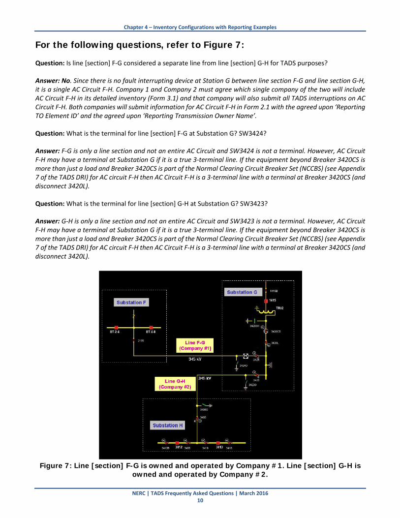
For the following questions, refer to Figure 7: Question: Is line [section] F-G considered a separate line from line [section] G-H for TADS purposes? Answer: No. Since there is no fault interrupting device at Station G between line section F-G and line section G-H, it is a single AC Circuit F-H. Company 1 and Company 2 must agree which single company of the two will include AC Circuit F-H in its detailed inventory (Form 3.1) and that company will also submit all TADS interruptions on AC Circuit F-H. Both companies will submit information for AC Circuit F-H in Form 2.1 with the agreed upon ‘Reporting TO Element ID’ and the agreed upon ‘Reporting Transmission Owner Name’. Question: What is the terminal for line [section] F-G at Substation G? SW3424? Answer: F-G is only a line section and not an entire AC Circuit and SW3424 is not a terminal. However, AC Circuit F-H may have a terminal at Substation G if it is a true 3-terminal line. If the equipment beyond Breaker 3420CS is more than just a load and Breaker 3420CS is part of the Normal Clearing Circuit Breaker Set (NCCBS) (see Appendix 7 of the TADS DRI) for AC circuit F-H then AC Circuit F-H is a 3-terminal line with a terminal at Breaker 3420CS (and disconnect 3420L). Question: What is the terminal for line [section] G-H at Substation G? SW3423? Answer: G-H is only a line section and not an entire AC Circuit and SW3423 is not a terminal. However, AC Circuit F-H may have a terminal at Substation G if it is a true 3-terminal line. If the equipment beyond Breaker 3420CS is more than just a load and Breaker 3420CS is part of the Normal Clearing Circuit Breaker Set (NCCBS) (see Appendix 7 of the TADS DRI) for AC circuit F-H then AC Circuit F-H is a 3-terminal line with a terminal at Breaker 3420CS (and disconnect 3420L).
Figure 7: Line [section] F-G is owned and operated by Company #1. Line [section] G-H is
owned and operated by Company #2.
NERC | TADS Frequently Asked Questions | March 2016 10
Chapter 4 – Inventory Configurations with Reporting Examples
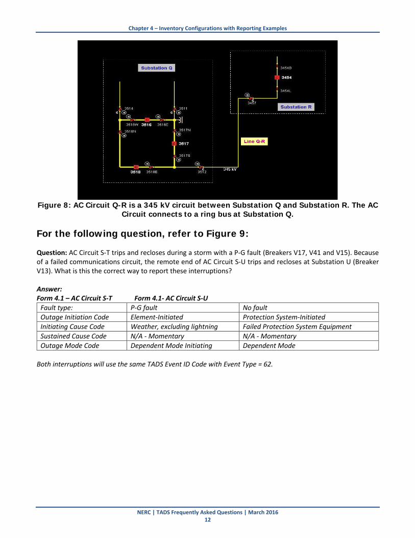
Note: There is no fault current interrupting device between line section F-G and line section G-H. When one line encounters a fault, both lines sections must trip in order to clear the fault. For the following questions, refer to Figure 8: Question: What is the terminal of AC Circuit Q-R at substation Q? Answer: The terminal for AC Circuit Q-R at substation Q would comprise the switches/breakers: 3512, 3518E, 3518N, 3518, 3517S, 3517N and 3517. To determine whether AC Circuit Q-R meets the definition of an In-Service State (see Appendix 7), you must determine whether power can flow from Substation Q to Station R (or vice-versa). At Substation Q: First, switch 3512 must be closed. Secondly, either Breaker 3518 and its associated disconnects (3518N and 3518E) OR Breaker 3518 and its associated disconnects (3517N and 3517S) must be closed. At Substation R: 3454, 3454B, 3454L and 3457 must all be closed. Question: If both Breaker 3517 and Breaker 3518 are open at Substation Q but AC Circuit Q-R remains energized from Substation R and SW 3512 remains closed, is AC Circuit Q-R in an In-Service State? Answer: No. AC Circuit Q-R is not considered in an In-Service state because it is not connected at all of its terminals (Substation Q) (even though the AC Circuit is energized). It is no longer possible for power to flow from Substation Q to Substation R. Question: What is the terminal of AC Circuit Q-R at Substation R? Answer: The terminal at substation R for Line Q-R would consist of the switches/breakers: Switch 3457 and Breaker 3454 and its associated disconnects (3454B and 3554L). All of these would need to be closed for AC Circuit Q-R to be connected at its terminal at Substation R. Question: Assume that all breakers and switches at Substation Q are closed and AC Circuit Q-R is energized from Substation Q. If Breaker 3454 is opened at Substation R, but SW 3457 and SW 3454L remain closed, is AC Circuit Q-R still in an In-Service State? Answer: No. AC Circuit Q-R is not considered in an In-Service State because it is not connected at all of its terminals (Substation R) (even though the AC Circuit is energized). It is no longer possible for power to flow from Substation Q to Substation R (or vice-versa). Assume that all breakers and switches at Substation Q are closed and AC Circuit Q-R is energized from Substation Q. If SW 3454L is opened with SW 3457 closed at Substation R, is AC Circuit Q-R still in an In-Service State? Answer: No. AC Circuit Q-R is not considered in an In-Service State because it is not connected at all of its terminals (Substation R) (even though the AC Circuit is energized). It is no longer possible for power to flow from Substation Q to Substation R (or vice-versa).
NERC | TADS Frequently Asked Questions | March 2016 11
Chapter 4 – Inventory Configurations with Reporting Examples
Figure 8: AC Circuit Q-R is a 345 kV circuit between Substation Q and Substation R. The AC
Circuit connects to a ring bus at Substation Q. For the following question, refer to Figure 9: Question: AC Circuit S-T trips and recloses during a storm with a P-G fault (Breakers V17, V41 and V15). Because of a failed communications circuit, the remote end of AC Circuit S-U trips and recloses at Substation U (Breaker V13). What is this the correct way to report these interruptions? Answer: Form 4.1 – AC Circuit S-T Form 4.1- AC Circuit S-U
Fault type: P-G fault No fault Outage Initiation Code Element-Initiated Protection System-Initiated Initiating Cause Code Weather, excluding lightning Failed Protection System Equipment Sustained Cause Code N/A - Momentary N/A - Momentary Outage Mode Code Dependent Mode Initiating Dependent Mode
Both interruptions will use the same TADS Event ID Code with Event Type = 62.
NERC | TADS Frequently Asked Questions | March 2016 12

Chapter 4 – Inventory Configurations with Reporting Examples
Figure 9: AC Circuit S-T is a 345 kV circuit between Substation S and Substation T.
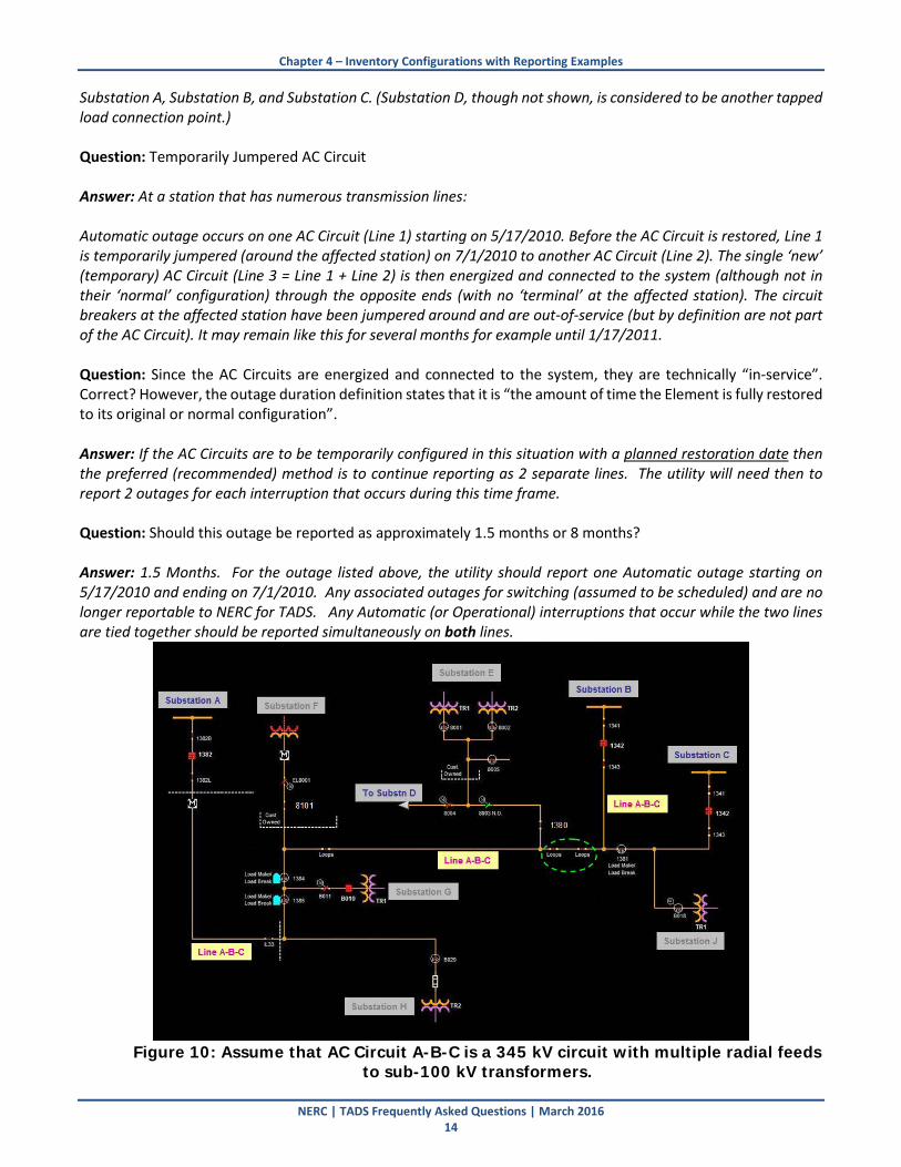
For the following questions, refer to Figure 10: Question: Assume that loops are opened as circled in green in the diagram, but the AC Circuit is fully energized and all breakers are closed. Is this AC Circuit in an In-Service State with the loops opened? (For this example, Substations A, B, and C (3 terminal line) are considered to be networked transmission stations and Substations D, E, F, G, H, and J are considered to be tapped load connection points on the AC Circuit A-B-C.) Answer: No. With the loops opened in the middle of AC Circuit A-B-C, the AC Circuit is no longer in an In-Service State. The intent of “connected at all of its terminals to the system” in the definition of In-Service State is that power can freely flow between all of the Element’s terminals (in this case: Substation A, Substation B, and Substation C). With any of the loops (or a switch such as IL33, 1384, 1385, or 1381) open in the middle of the AC Circuit, power can no longer flow between all the terminals and the AC Circuit is no longer in an In-Service State. Question: If switch 8101 is opened at Substation F with all other breakers/switches closed and the line energized, is AC Circuit A-B-C in service? Answer: Yes, AC Circuit A-B-C is still in an In-Service State. Substation F is a tapped load connection point to the AC Circuit A-B-C and is not essential for the transmission line for power flow between Substation A, Substation B, and Substation C. Substation F and its associated tap line is not a terminal of AC Circuit A-B-C. Question: If inline switch 1380 near Substation E is opened with all other breakers/switches closed and the line energized, is AC Circuit A-B-C in service? Answer: Yes, AC Circuit A-B-C is still in an In-Service State. Substation E and Substation D are tapped load connection points to the AC Circuit A-B-C and is not essential for the transmission line for power flow between
NERC | TADS Frequently Asked Questions | March 2016 13
Chapter 4 – Inventory Configurations with Reporting Examples
Substation A, Substation B, and Substation C. (Substation D, though not shown, is considered to be another tapped load connection point.) Question: Temporarily Jumpered AC Circuit Answer: At a station that has numerous transmission lines: Automatic outage occurs on one AC Circuit (Line 1) starting on 5/17/2010. Before the AC Circuit is restored, Line 1 is temporarily jumpered (around the affected station) on 7/1/2010 to another AC Circuit (Line 2). The single ‘new’ (temporary) AC Circuit (Line 3 = Line 1 + Line 2) is then energized and connected to the system (although not in their ‘normal’ configuration) through the opposite ends (with no ‘terminal’ at the affected station). The circuit breakers at the affected station have been jumpered around and are out-of-service (but by definition are not part of the AC Circuit). It may remain like this for several months for example until 1/17/2011. Question: Since the AC Circuits are energized and connected to the system, they are technically “in-service”. Correct? However, the outage duration definition states that it is “the amount of time the Element is fully restored to its original or normal configuration”. Answer: If the AC Circuits are to be temporarily configured in this situation with a planned restoration date then the preferred (recommended) method is to continue reporting as 2 separate lines. The utility will need then to report 2 outages for each interruption that occurs during this time frame. Question: Should this outage be reported as approximately 1.5 months or 8 months? Answer: 1.5 Months. For the outage listed above, the utility should report one Automatic outage starting on 5/17/2010 and ending on 7/1/2010. Any associated outages for switching (assumed to be scheduled) and are no longer reportable to NERC for TADS. Any Automatic (or Operational) interruptions that occur while the two lines are tied together should be reported simultaneously on both lines.
Figure 10: Assume that AC Circuit A-B-C is a 345 kV circuit with multiple radial feeds
to sub-100 kV transformers.
NERC | TADS Frequently Asked Questions | March 2016 14

Chapter 5 – Reporting Changes and Portal Issues Question: Since the TADS reporting based new BES Definitions will begin January 1, 2015, will the Quarter 4 inventory data, normally submitted by the January 15, 2015 deadline, need to include the 100kV and above elements? Answer: The January 15, 2015 deadline applies to 2014 Quarter 4 TADS data. All Elements 200 kV and above should be reported for 2014 Quarter 4 reporting. Reporting of 100 – 199 kV Elements and Less than 100 kV Bulk Electric System Elements should commence with 2015 Quarter 1 reporting, commencing with all Outages beginning on January 1, 2015 00:00:01 UTC. Question: Could you address an issue SERC and a few TOs are having with the Duration fields? TADS exports data to a CVS file format, but every Duration field does not translate well to the Excel environment. This necessitates a lot of manual interventions in order to normalize the data to a common format. Answer: For Detailed Outage Data: On the “Filter” options, there is a checkbox for “Change Format for Export”. This will convert durations to “dddd.tttt” upon export, where “dddd” is the number of days and “tttt” is a fractional day. This is the native Excel format for time durations, so you should be able to add it to the Outage start time to get an Outage end time. For Summary Outage Data: NERC Staff and the vendor are working to resolve the issue. Question: IMEA is registered as a TO in RF on behalf of an IMEA member with a 138 kV municipal system that serves only local distribution. IMEA will qualify for Exclusion 1 (Radial Systems) and Exclusion 3 (Local Networks) under the new BES Definition which becomes effective July 1, 2014; this will allow IMEA to deregister as a TO. If IMEA needs to take additional action, I would appreciate your advice Answer: Although some steps may not be applicable in your case, here are the steps that should occur for either TOs who are losing the TO function or when their Element(s) become BES Exempt:
1. For each Element that is BES Exempt:
a. In the proper 3.X form, indicate the Element is BES Exempt by checking the “BES Exempt” field. In the XML, a Boolean TRUE can be used for Bulk Upload.
b. Also, set the Retirement Date(s) of the Element(s) to the date the Bulk Electric System exemption request was approved by NERC. If your Elements are self-identified on January 1, 2015 as being exempt, you would enter January 1, 2015.
2. As long as your company maintains a TO function (prior to deregistration), you would indicate that you are either a reporting or non-reporting TADS Transmission Owner by filling Form 1.1 each year until your deregistration is complete.
3. Once the TO deregistration is approved, you must send an e-mail to [email protected] indicating your company has deregistered. NERC staff will verify that your company has deregistered successfully from the TO function, and you will no longer be responsible for TADS reporting as of your company’s deregistration date.
Question: Could you address the training for TOs TADS reporting when we go to the BES TADS Elements? NERC Training of the regions last November had a slide showing that 2015 Q1 reporting would be for all BES TADS Elements.
NERC | TADS Frequently Asked Questions | March 2016 15
Chapter 5 – Reporting Changes and Portal Issues
Answer: Training videos are available to address BES TADS elements. TAD collects transmission outage data in a common format for:
• BES AC Circuits (Overhead and Underground)
• Transmission Transformers (No Generator Step-up Units)
• BES AC/DC Back-to-Back Converters
• BES DC Circuits Additional questions on what qualifies as a BES element can be found on the NERC Bulk Electric System (BES) Definition, Notification, and Exception Process website Question: With the expanding scope of TADS reporting in 2015, will there be a significant change in the workbook to accommodate this reporting? If so, when an updated workbook will be available so that entities can begin compiling inventory data for sub-200 kV elements? Answer: The changes to the workbook should not be too significant from 2014 reporting except for the addition of the Voltage Classes “Less than 100 kV (BES Only)” and “100-199 kV”. It is recommended that you start collecting your inventory on the 2014 TADS workbook if you want to collect it ahead of time. You would need to type in the new Voltages Classes for Elements below 200 kV in the 2014 workbook and then copy/paste it to the 2015 workbook to use in 2015. The 2015 workbook, of course, will include those Voltage Classes in the proper dropdowns. Question: When we start reporting 161 kV information in 2015, will it be just Automatic (Unplanned) outages or both Non Automatic (Planned) and Automatic (Unplanned). Seems to me I heard that only Automatic outages will need to be entered for 161 KV. Also is there a site where I can get a summary of reporting requirements for 2015 or is it still in the works? Answer: On November 5, 2015, the NERC Board of Trustees approved the discontinuation of Planned Outages in the Transmission Availability Data System (TADS). The retroactive effective date is January 1, 2015. For Elements in the 0 – 99kV and 100-199 kV Voltage Classes, only Sustained Outages should be reported. These are Automatic Outages lasting 1 minute or longer. Question: Should Form 3.4 be completed quarterly, or, is it a form that needs to be completed only in Q4? Answer: Form 3.4, because it is in the Inventory Series (Forms 3.X) should be completed only in Q4. There is a known issue where this form will not validate correctly until Quarter 4 reporting is complete. If you encounter the validation error on Form 3.4, you can ignore it until Quarter 4 reporting. Question: When trying to validate data, we get a fatal error due to the TO Element Identifier in Form 6.1 not accepting the same number of characters as Form 3.1 in the Inventory Data Detail Entry. Is there a character limit for Outage ID and Event ID? Do Outage ID and Event ID codes need to be in a certain format? Answer: The DRI does not provide the character limitations or an acceptable list of special characters for the Element ID, Event ID, or Outage ID. It does state that it is a unique alphanumeric identifier; therefore, it is up to each reporting entity to establish. No prescriptive naming conventions apply. Character limitation for Element Identifier on Forms 3.1, 4.x, and 6.x is 125 characters. There are no special character restrictions.
NERC | TADS Frequently Asked Questions | March 2016 16