Embed Size (px)
Citation preview
Translation of ER-diagram into Relational Schema
Dr. Sunnie S. Chung
CIS430/530

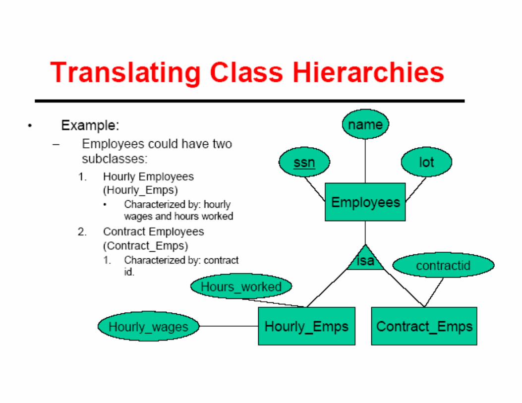
Learning Objectives� Define each of the following database terms
� Relation
� Primary key
� Foreign key
� Referential integrity
� Field
� Data type
� Null value
9.29.2
� Discuss the role of designing databases in the
analysis and design of an information system
� Learn how to transform an entity-relationship (ER)
Diagram into an equivalent set of well-structured
relations
9.49.4
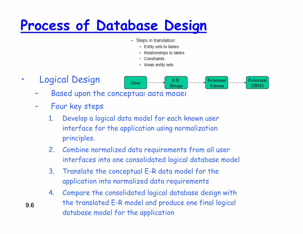
Process of Database Design
• Logical Design
– Based upon the conceptual data model
– Four key steps
1. Develop a logical data model for each known user
interface for the application using normalization
principles.
2. Combine normalized data requirements from all user
interfaces into one consolidated logical database model
3. Translate the conceptual E-R data model for the
application into normalized data requirements
4. Compare the consolidated logical database design with
the translated E-R model and produce one final logical
database model for the application9.69.6

9.79.7
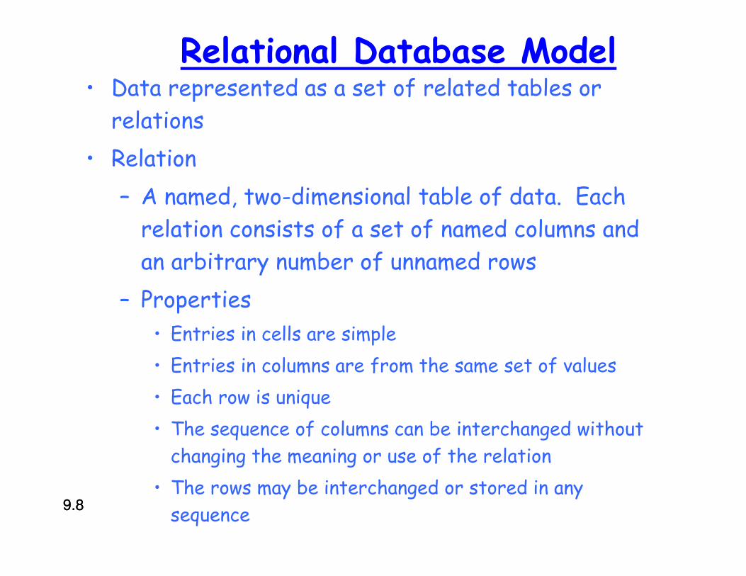
Relational Database Model• Data represented as a set of related tables or
relations
• Relation
– A named, two-dimensional table of data. Each
relation consists of a set of named columns and
an arbitrary number of unnamed rows
– Properties
• Entries in cells are simple
• Entries in columns are from the same set of values
• Each row is unique
• The sequence of columns can be interchanged without
changing the meaning or use of the relation
• The rows may be interchanged or stored in any
sequence9.89.8
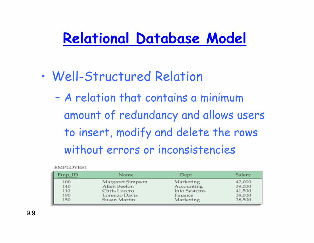
Relational Database Model
• Well-Structured Relation
– A relation that contains a minimum
amount of redundancy and allows users
to insert, modify and delete the rows
without errors or inconsistencies
9.99.9
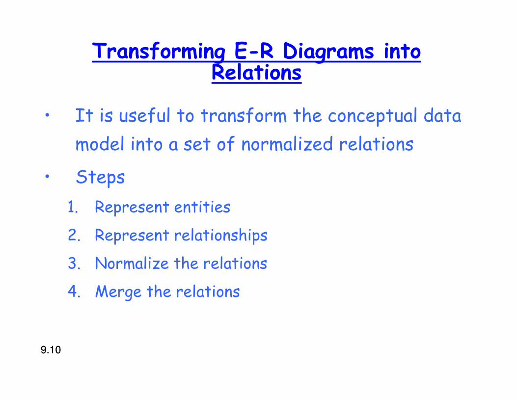
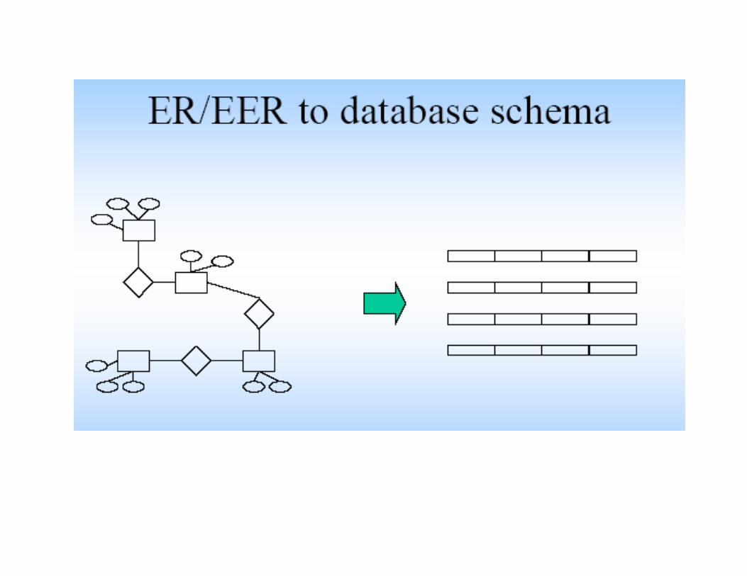
Transforming E-R Diagrams into Relations
• It is useful to transform the conceptual data
model into a set of normalized relations
• Steps
1. Represent entities
2. Represent relationships
3. Normalize the relations
4. Merge the relations
9.109.10
Refining the ER Design for the COMPANY Database
� Change attributes that represent
relationships into relationship types
� Determine cardinality ratio and
participation constraint of each
relationship type
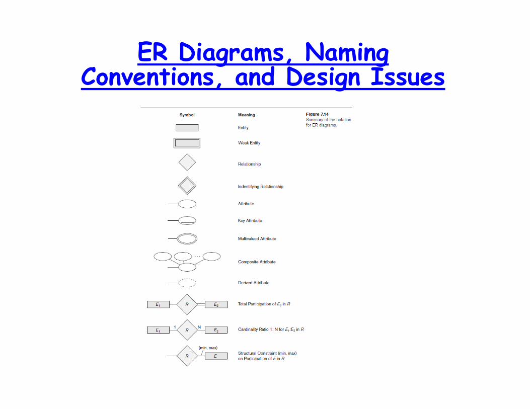
ER Diagrams, Naming Conventions, and Design Issues

Design Choices for ER Conceptual Design
� Model concept first as an attribute
� Refined into a relationship if attribute is a
reference to another entity type
� Attribute that exists in several entity
types may be elevated to an independent
entity type
� Can also be applied in the inverse
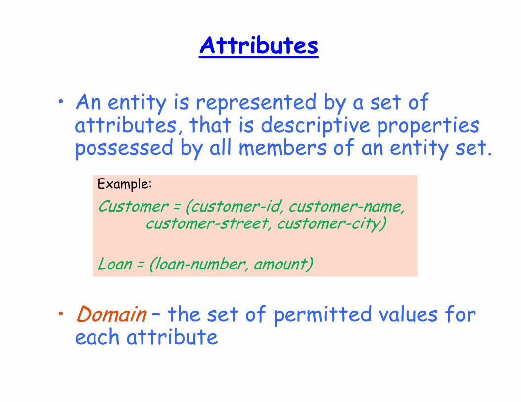
Attributes
• An entity is represented by a set of attributes, that is descriptive properties possessed by all members of an entity set.
• Domain – the set of permitted values for each attribute
Example:
Customer = (customer-id, customer-name, customer-street, customer-city)
Loan = (loan-number, amount)
Attributes
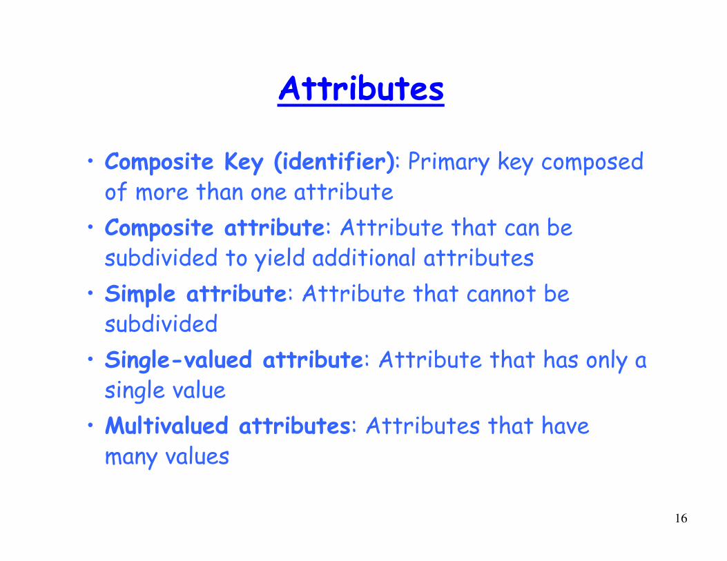
• Composite Key (identifier): Primary key composed of more than one attribute
• Composite attribute: Attribute that can be subdivided to yield additional attributes
• Simple attribute: Attribute that cannot be subdivided
• Single-valued attribute: Attribute that has only a single value
• Multivalued attributes: Attributes that have many values
16
Attributes
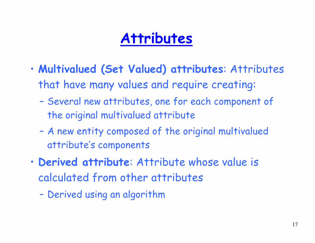
• Multivalued (Set Valued) attributes: Attributes
that have many values and require creating:
– Several new attributes, one for each component of
the original multivalued attribute
– A new entity composed of the original multivalued
attribute’s components
• Derived attribute: Attribute whose value is
calculated from other attributes
– Derived using an algorithm
17
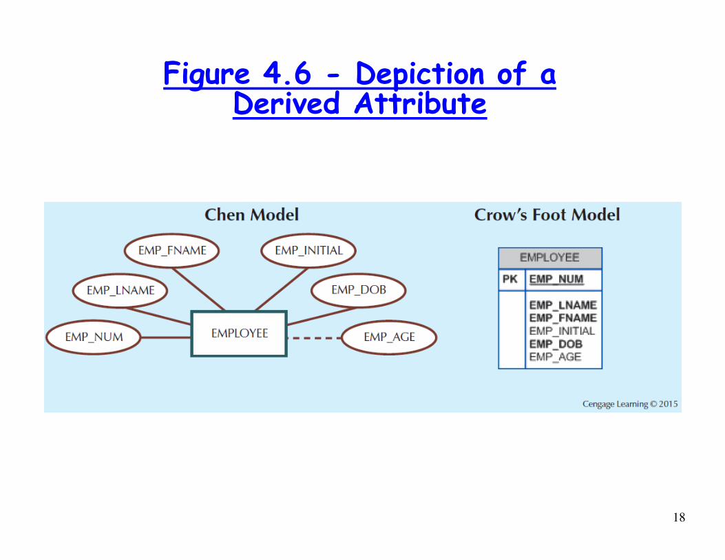
Figure 4.6 - Depiction of a Derived Attribute
18
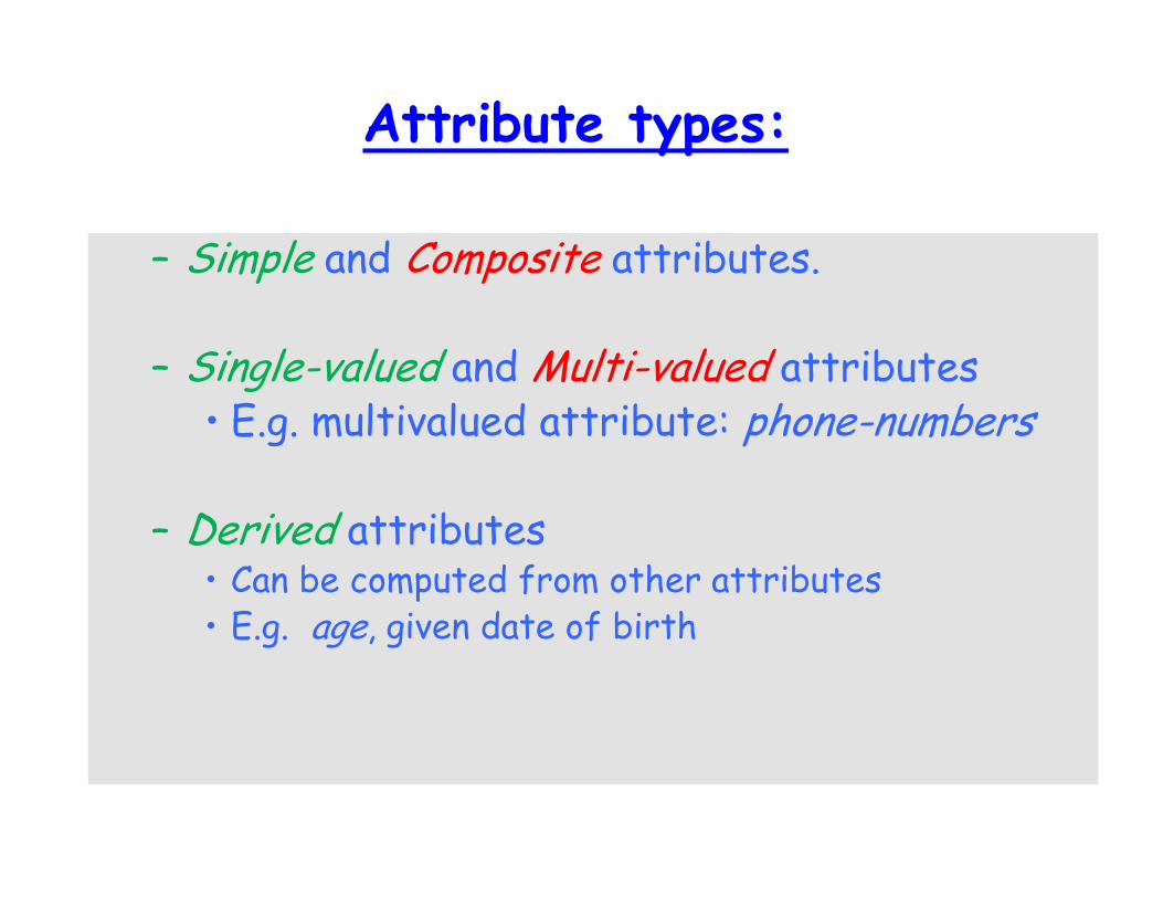
Attribute types:
– Simple and Composite attributes.
– Single-valued and Multi-valued attributes• E.g. multivalued attribute: phone-numbers
– Derived attributes• Can be computed from other attributes• E.g. age, given date of birth
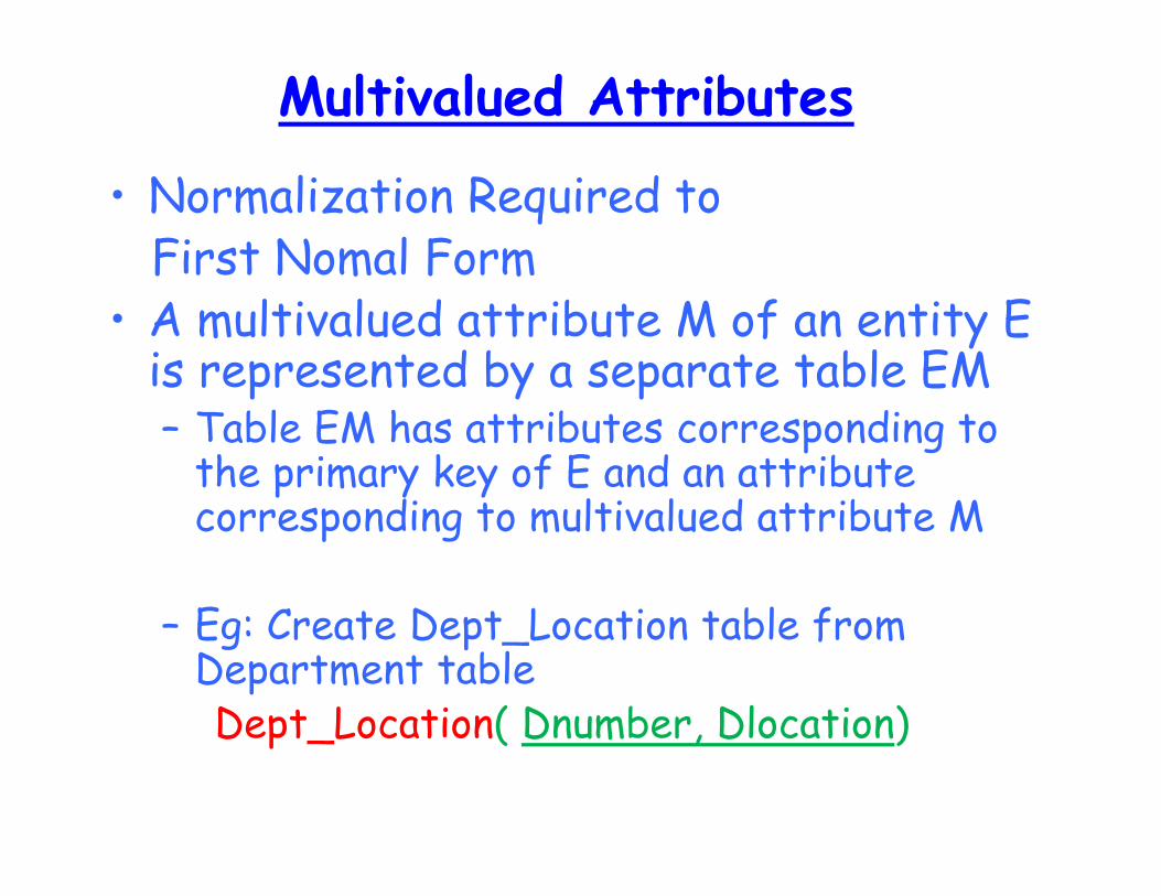
Multivalued Attributes
• Normalization Required toFirst Nomal Form
• A multivalued attribute M of an entity E is represented by a separate table EM– Table EM has attributes corresponding to
the primary key of E and an attribute corresponding to multivalued attribute M
– Eg: Create Dept_Location table from Department tableDept_Location( Dnumber, Dlocation)
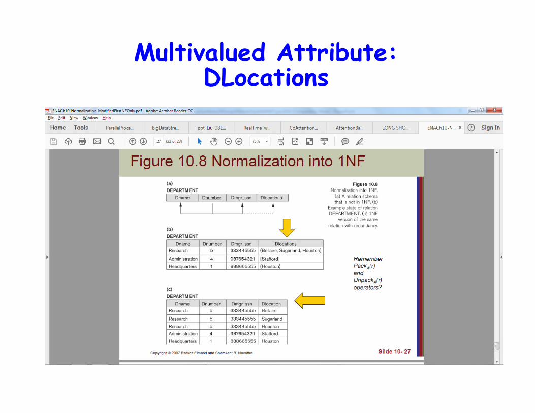
Multivalued Attribute: DLocations
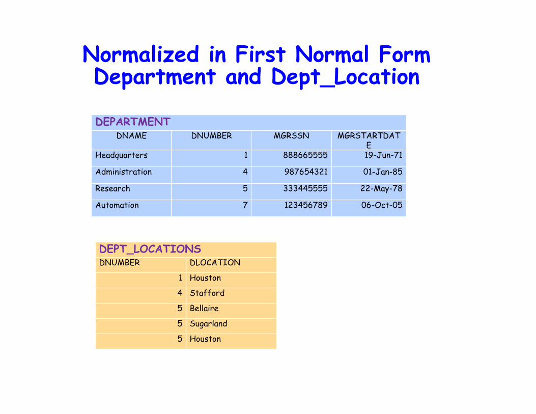
Normalized in First Normal FormDepartment and Dept_Location
DEPARTMENTDNAME DNUMBER MGRSSN MGRSTARTDAT
EHeadquarters 1 888665555 19-Jun-71
Administration 4 987654321 01-Jan-85
Research 5 333445555 22-May-78
Automation 7 123456789 06-Oct-05
DEPT_LOCATIONSDNUMBER DLOCATION
1 Houston
4 Stafford
5 Bellaire
5 Sugarland
5 Houston
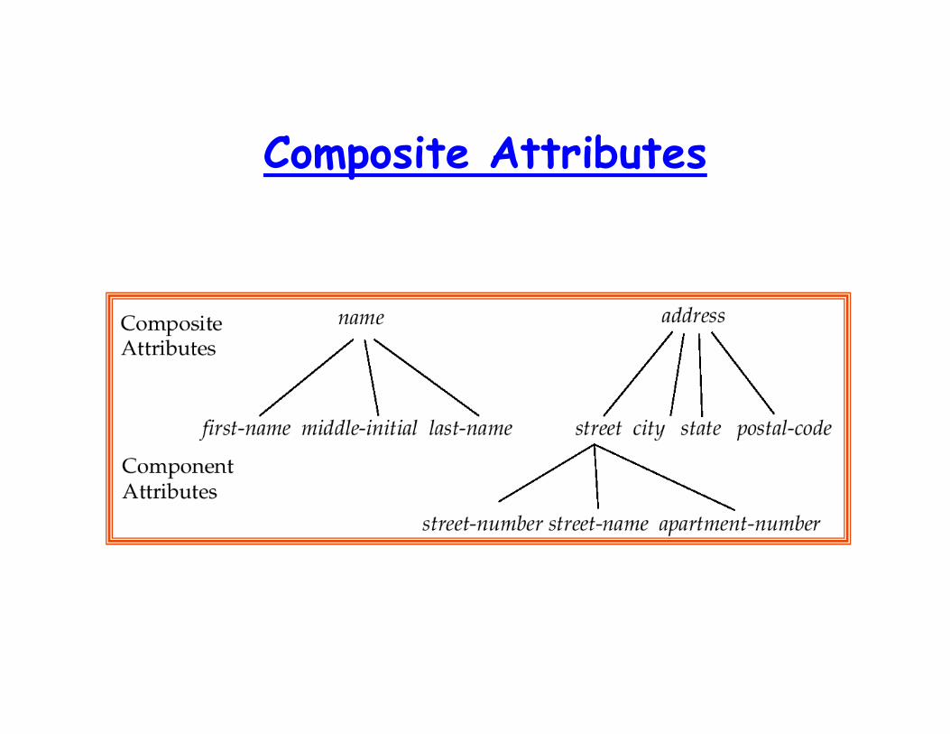
Composite Attributes

Three Ways in Transforming Composite Attribute
1. Flatten the Structure to One Attribute
eg: Address of Employee Table
2. Flatten the Structure to Multiple Attributes
eg: Name �
Lname, MI, Fname of Employee Table
3. Making the Composite attribute to
a Separate Table
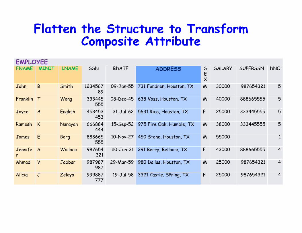
Flatten the Structure to TransformComposite Attribute
EMPLOYEEFNAME MINIT LNAME SSN BDATE ADDRESS S
EX
SALARY SUPERSSN DNO
John B Smith 123456789
09-Jan-55 731 Fondren, Houston, TX M 30000 987654321 5
Franklin T Wong 333445555
08-Dec-45 638 Voss, Houston, TX M 40000 888665555 5
Joyce A English 453453453
31-Jul-62 5631 Rice, Houston, TX F 25000 333445555 5
Ramesh K Narayan 666884444
15-Sep-52 975 Fire Oak, Humble, TX M 38000 333445555 5
James E Borg 888665555
10-Nov-27 450 Stone, Houston, TX M 55000 1
Jennifer
S Wallace 987654321
20-Jun-31 291 Berry, Bellaire, TX F 43000 888665555 4
Ahmad V Jabbar 987987987
29-Mar-59 980 Dallas, Houston, TX M 25000 987654321 4
Alicia J Zelaya 999887777
19-Jul-58 3321 Castle, SPring, TX F 25000 987654321 4
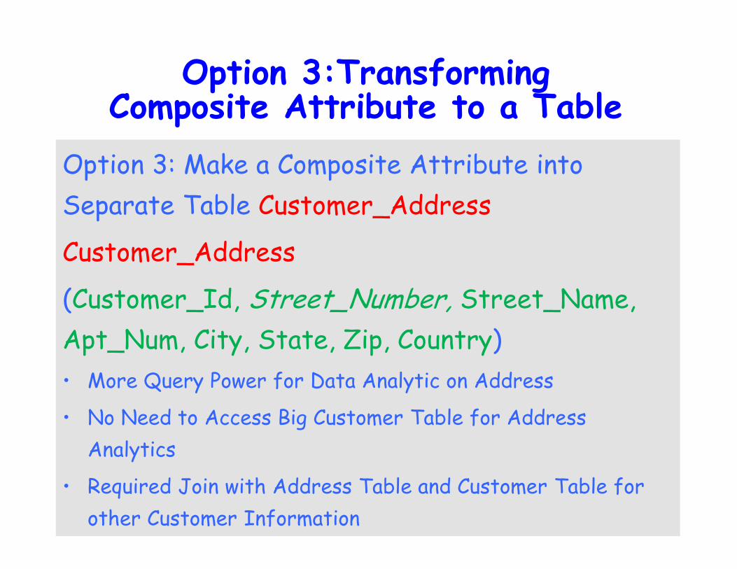
Option 3:Transforming Composite Attribute to a Table
Option 3: Make a Composite Attribute into
Separate Table Customer_Address
Customer_Address
(Customer_Id, Street_Number, Street_Name,
Apt_Num, City, State, Zip, Country)
• More Query Power for Data Analytic on Address
• No Need to Access Big Customer Table for Address
Analytics
• Required Join with Address Table and Customer Table for
other Customer Information
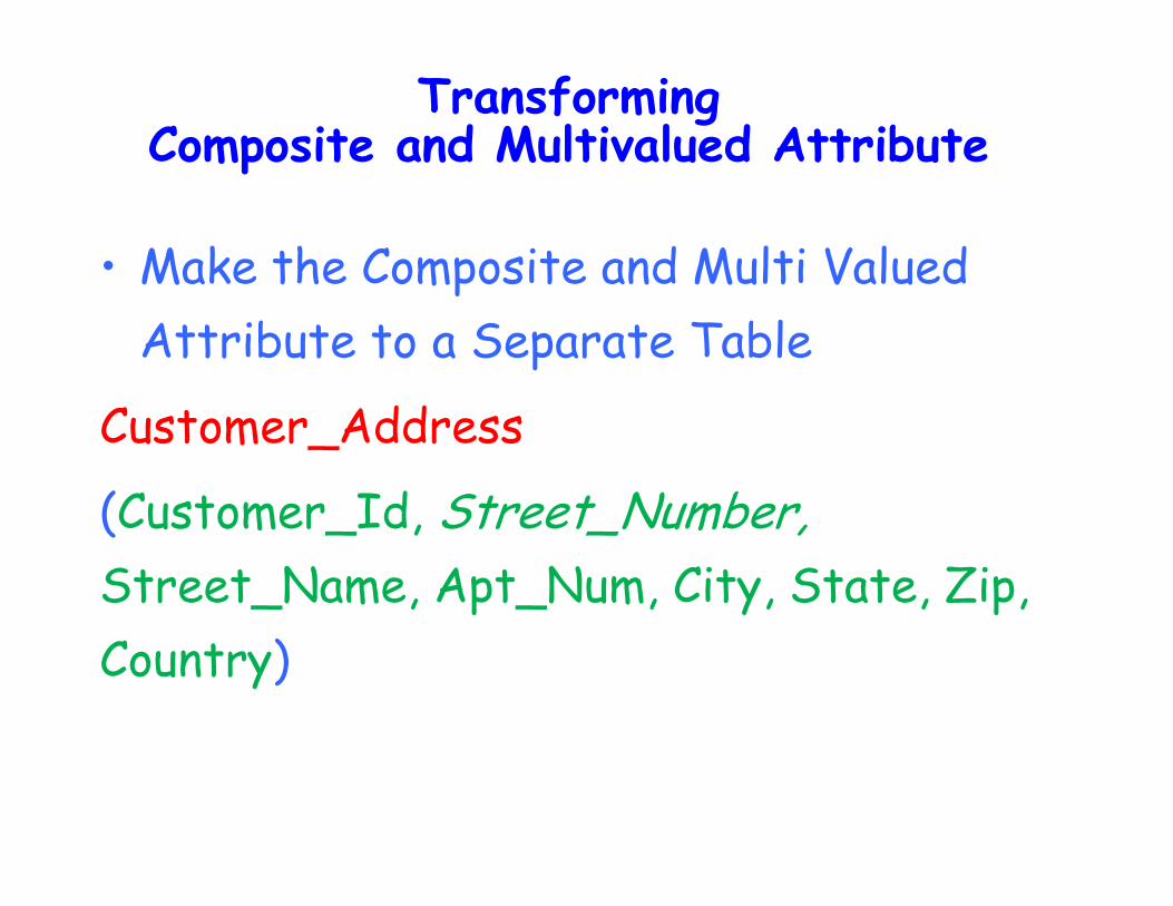
Transforming Composite and Multivalued Attribute
• Make the Composite and Multi Valued
Attribute to a Separate Table
Customer_Address
(Customer_Id, Street_Number,
Street_Name, Apt_Num, City, State, Zip,
Country)
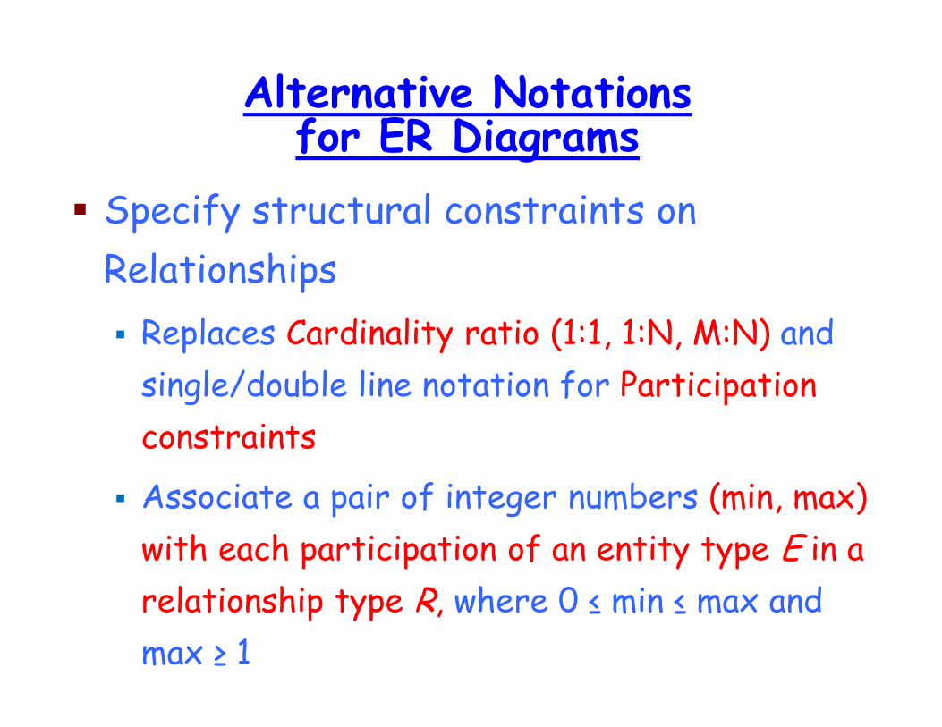
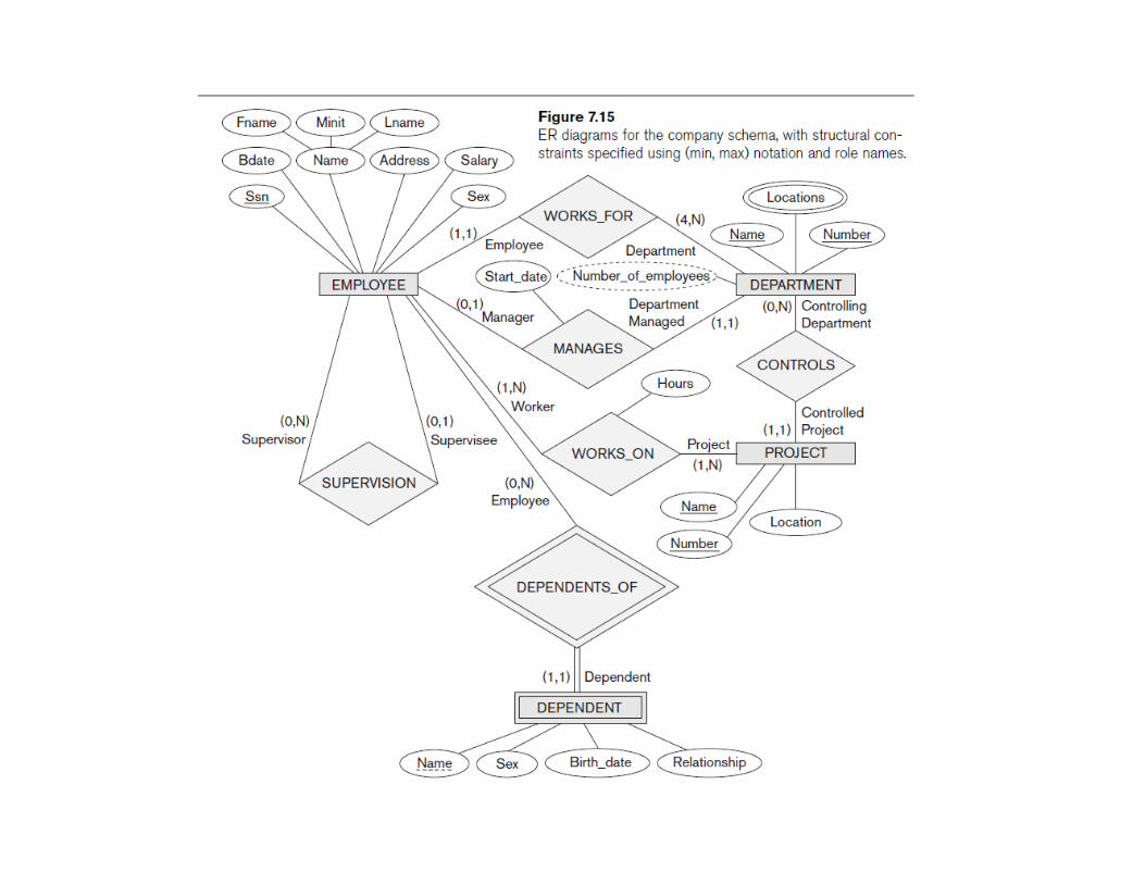
Alternative Notations for ER Diagrams
� Specify structural constraints on
Relationships
� Replaces Cardinality ratio (1:1, 1:N, M:N) and
single/double line notation for Participation
constraints
� Associate a pair of integer numbers (min, max)
with each participation of an entity type E in a
relationship type R, where 0 ≤ min ≤ max and
max ≥ 1
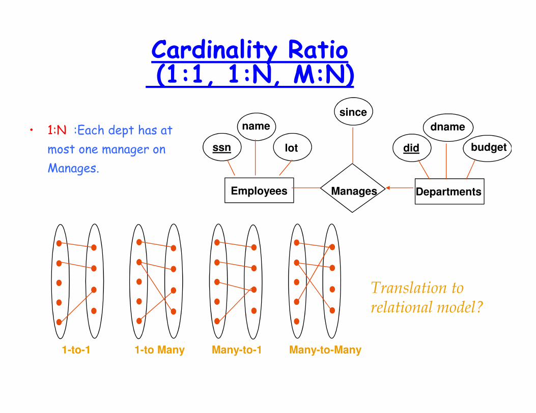
Cardinality Ratio(1:1, 1:N, M:N)
• 1:N :Each dept has at
most one manager on
Manages.
Translation to
relational model?
Many-to-Many1-to-1 1-to Many Many-to-1
dname
budgetdid
since
lot
name
ssn
ManagesEmployees Departments
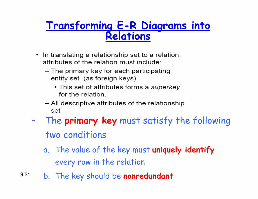
Transforming E-R Diagrams into Relations
– The primary key must satisfy the following
two conditions
a. The value of the key must uniquely identify
every row in the relation
b. The key should be nonredundant9.319.31
9.329.32
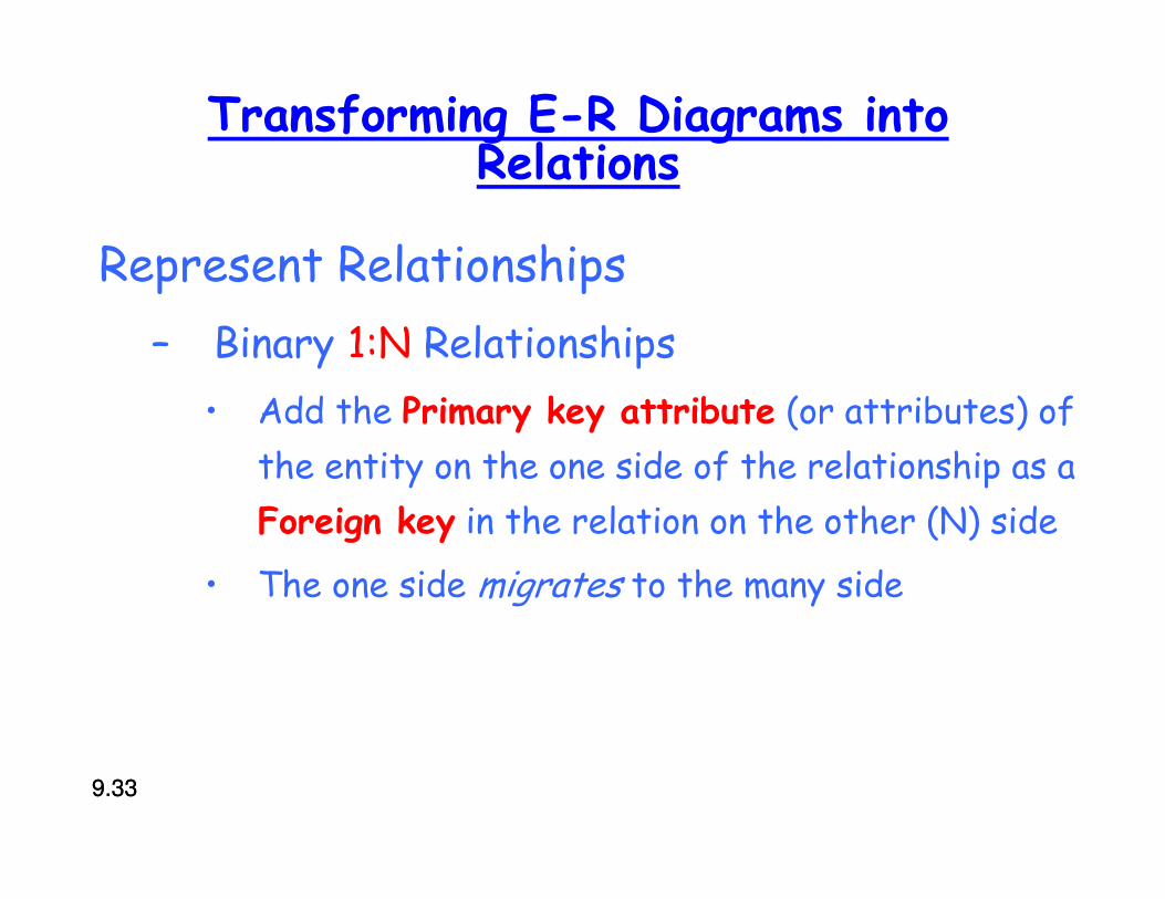
Transforming E-R Diagrams into Relations
Represent Relationships
– Binary 1:N Relationships
• Add the Primary key attribute (or attributes) of
the entity on the one side of the relationship as a
Foreign key in the relation on the other (N) side
• The one side migrates to the many side
9.339.33
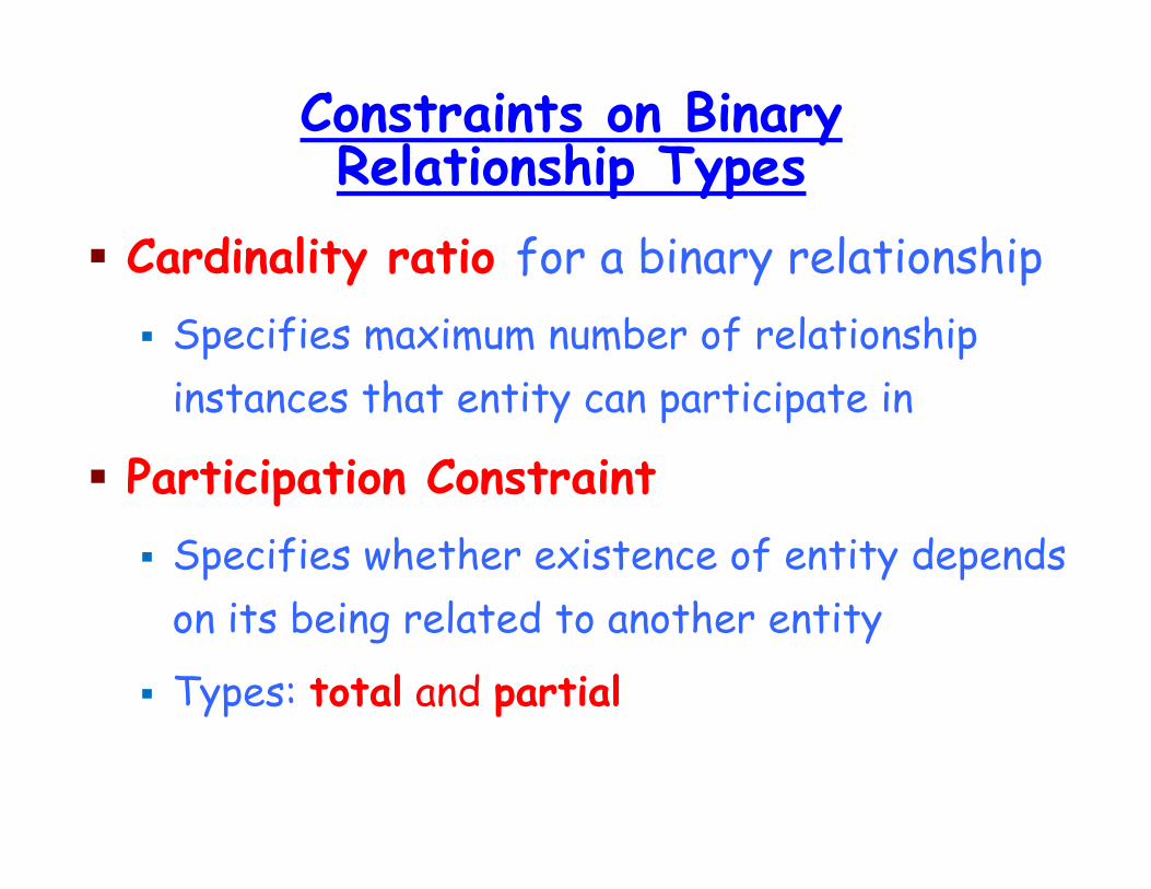
Constraints on Binary Relationship Types
� Cardinality ratio for a binary relationship
� Specifies maximum number of relationship
instances that entity can participate in
� Participation Constraint
� Specifies whether existence of entity depends
on its being related to another entity
� Types: total and partial
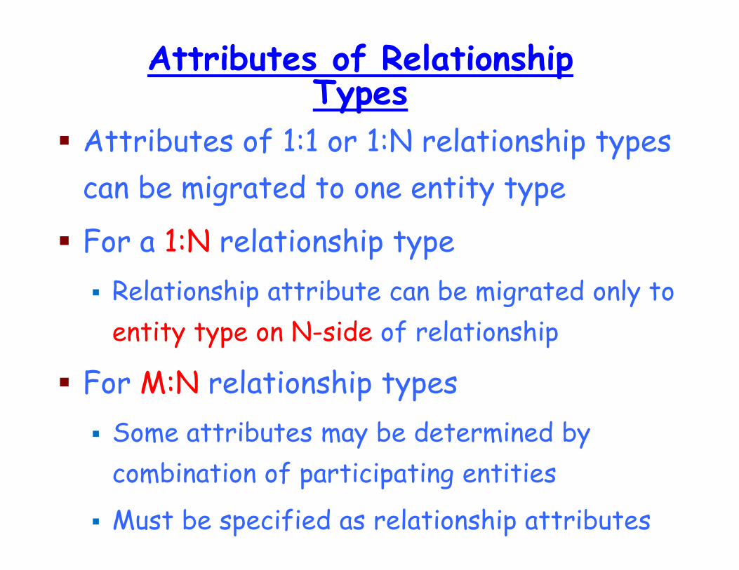
Attributes of Relationship Types
� Attributes of 1:1 or 1:N relationship types
can be migrated to one entity type
� For a 1:N relationship type
� Relationship attribute can be migrated only to
entity type on N-side of relationship
� For M:N relationship types
� Some attributes may be determined by
combination of participating entities
� Must be specified as relationship attributes
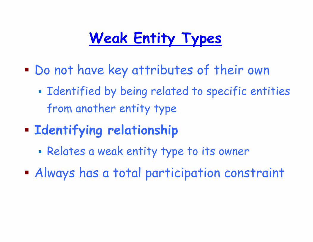
Weak Entity Types
� Do not have key attributes of their own
� Identified by being related to specific entities
from another entity type
� Identifying relationship
� Relates a weak entity type to its owner
� Always has a total participation constraint
9.379.37
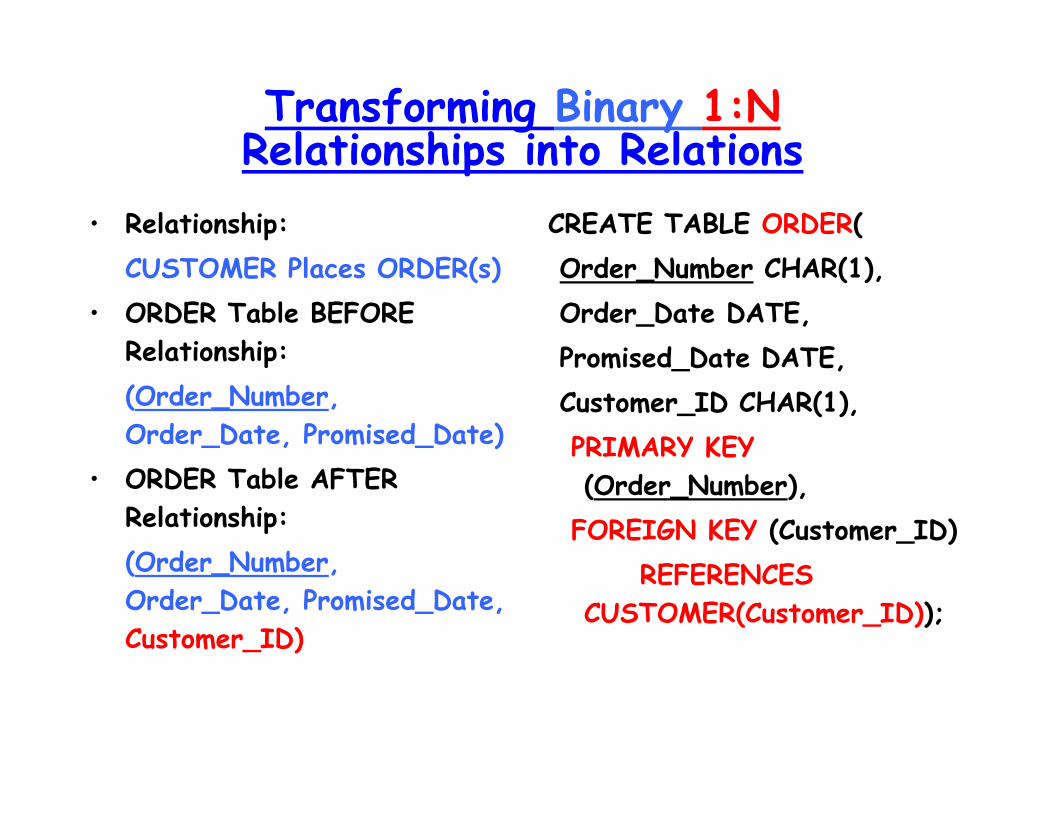
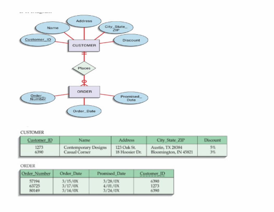
Transforming Binary 1:NRelationships into Relations
• Relationship:
CUSTOMER Places ORDER(s)
• ORDER Table BEFORE
Relationship:
(Order_Number,
Order_Date, Promised_Date)
• ORDER Table AFTER
Relationship:
(Order_Number,
Order_Date, Promised_Date,
Customer_ID)
CREATE TABLE ORDER(
Order_Number CHAR(1),
Order_Date DATE,
Promised_Date DATE,
Customer_ID CHAR(1),
PRIMARY KEY
(Order_Number),
FOREIGN KEY (Customer_ID)
REFERENCES
CUSTOMER(Customer_ID));
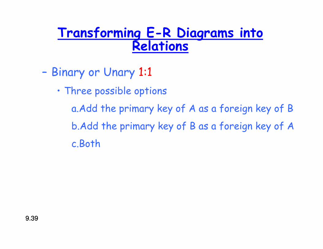
Transforming E-R Diagrams into Relations
– Binary or Unary 1:1
• Three possible options
a.Add the primary key of A as a foreign key of B
b.Add the primary key of B as a foreign key of A
c.Both
9.399.39
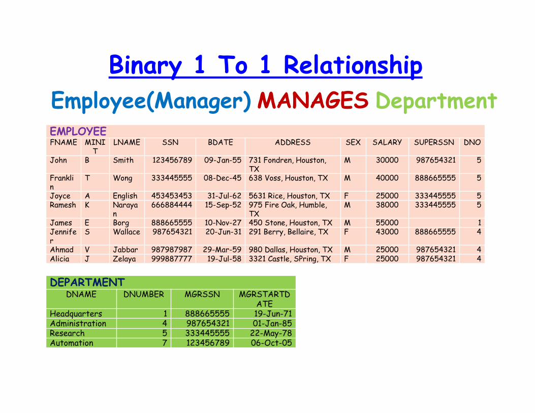
Binary 1 To 1 Relationship
Employee(Manager) MANAGES DepartmentEMPLOYEEFNAME MINI
TLNAME SSN BDATE ADDRESS SEX SALARY SUPERSSN DNO
John B Smith 123456789 09-Jan-55 731 Fondren, Houston, TX
M 30000 987654321 5
Franklin
T Wong 333445555 08-Dec-45 638 Voss, Houston, TX M 40000 888665555 5
Joyce A English 453453453 31-Jul-62 5631 Rice, Houston, TX F 25000 333445555 5Ramesh K Naraya
n666884444 15-Sep-52 975 Fire Oak, Humble,
TXM 38000 333445555 5
James E Borg 888665555 10-Nov-27 450 Stone, Houston, TX M 55000 1Jennifer
S Wallace 987654321 20-Jun-31 291 Berry, Bellaire, TX F 43000 888665555 4
Ahmad V Jabbar 987987987 29-Mar-59 980 Dallas, Houston, TX M 25000 987654321 4Alicia J Zelaya 999887777 19-Jul-58 3321 Castle, SPring, TX F 25000 987654321 4
DEPARTMENTDNAME DNUMBER MGRSSN MGRSTARTD
ATEHeadquarters 1 888665555 19-Jun-71Administration 4 987654321 01-Jan-85Research 5 333445555 22-May-78Automation 7 123456789 06-Oct-05
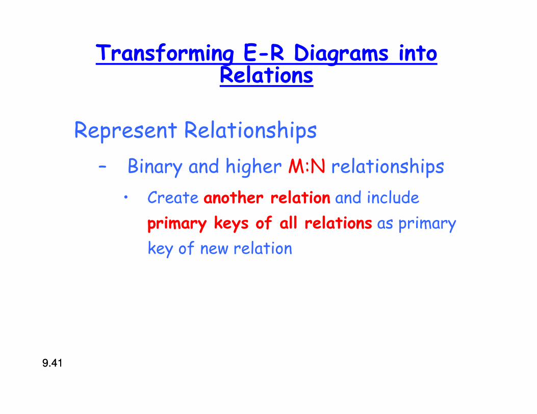
Transforming E-R Diagrams into Relations
Represent Relationships
– Binary and higher M:N relationships
• Create another relation and include
primary keys of all relations as primary
key of new relation
9.419.41
9.429.42
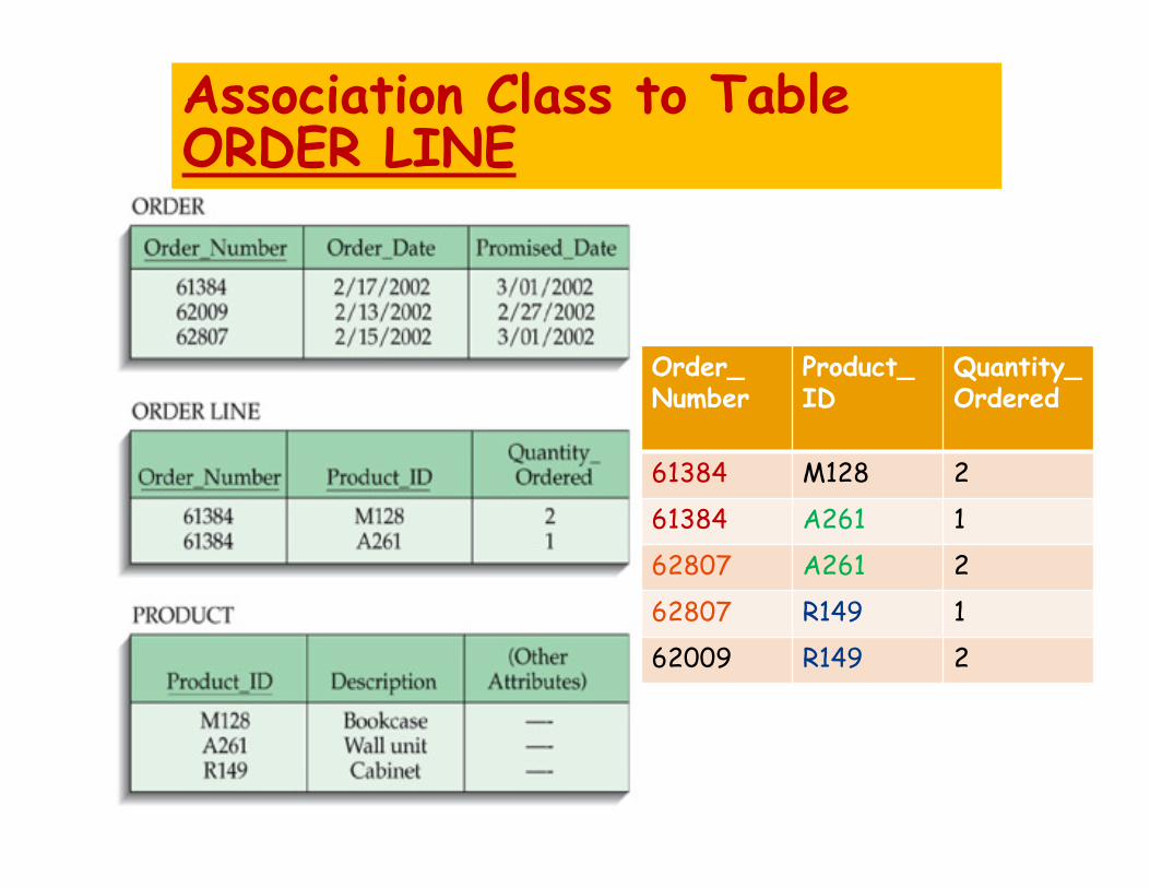
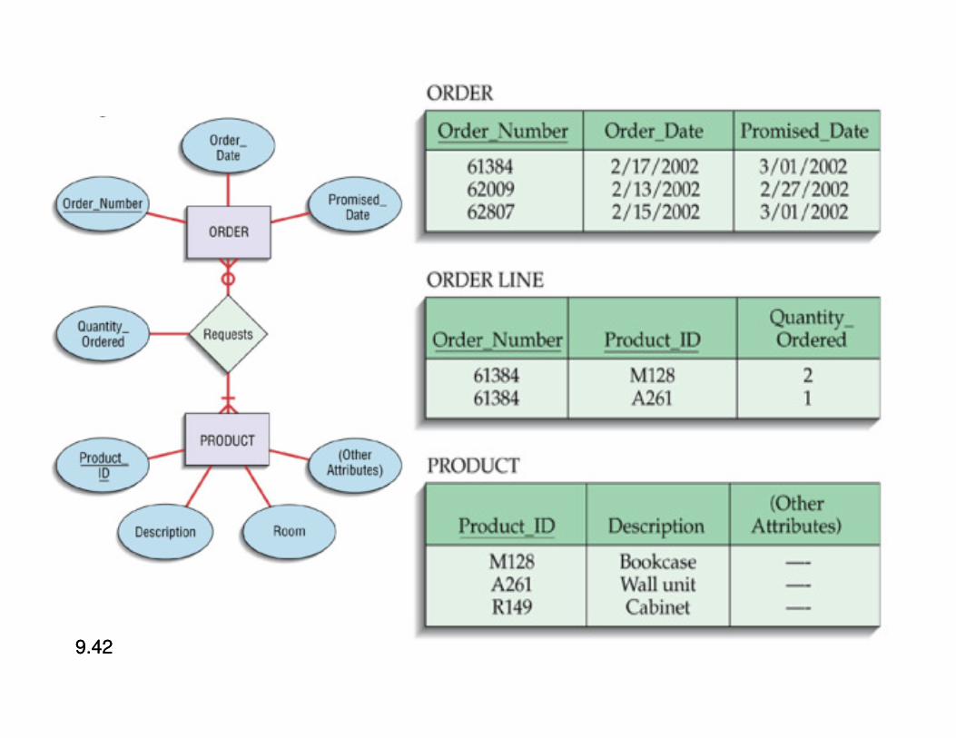
Association Class to TableORDER LINE
Order_Number
Product_ID
Quantity_Ordered
61384 M128 2
61384 A261 1
62807 A261 2
62807 R149 1
62009 R149 2
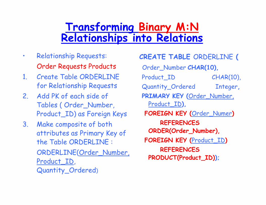
Transforming Binary M:NRelationships into Relations
• Relationship Requests:
Order Requests Products
1. Create Table ORDERLINE for Relationship Requests
2. Add PK of each side of Tables ( Order_Number, Product_ID) as Foreign Keys
3. Make composite of both attributes as Primary Key of the Table ORDERLINE :
ORDERLINE(Order_Number, Product_ID, Quantity_Ordered)
CREATE TABLE ORDERLINE (
Order_Number CHAR(10),
Product_ID CHAR(10),
Quantity_Ordered Integer,
PRIMARY KEY (Order_Number, Product_ID),
FOREIGN KEY (Order_Numer)
REFERENCES ORDER(Order_Number),
FOREIGN KEY (Product_ID)
REFERENCES PRODUCT(Product_ID));
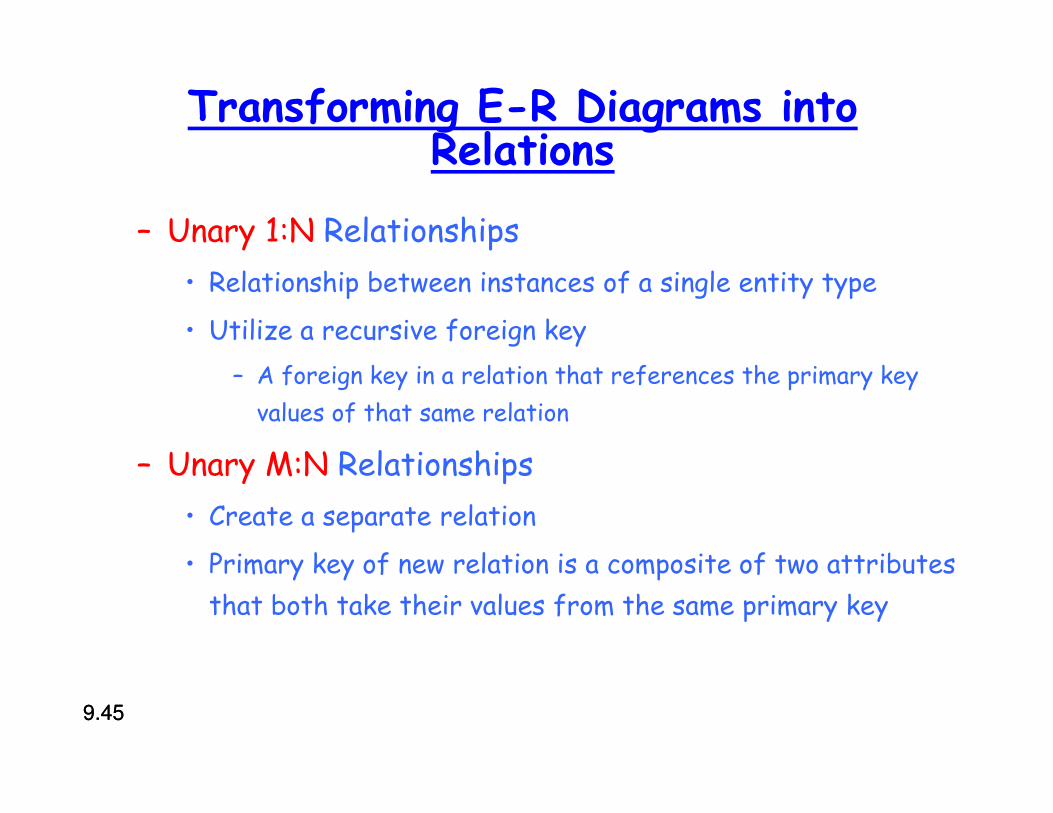
Transforming E-R Diagrams into Relations
– Unary 1:N Relationships
• Relationship between instances of a single entity type
• Utilize a recursive foreign key
– A foreign key in a relation that references the primary key
values of that same relation
– Unary M:N Relationships
• Create a separate relation
• Primary key of new relation is a composite of two attributes
that both take their values from the same primary key
9.459.45
9.469.46
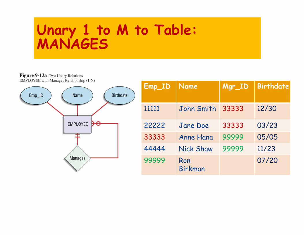
Unary 1 to M to Table:MANAGES
Emp_ID Name Mgr_ID Birthdate
11111 John Smith 33333 12/30
22222 Jane Doe 33333 03/23
33333 Anne Hana 99999 05/05
44444 Nick Shaw 99999 11/23
99999 RonBirkman
07/20
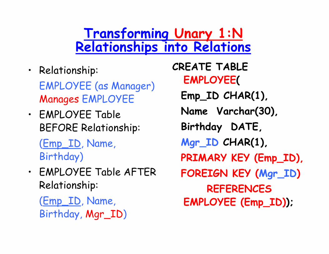
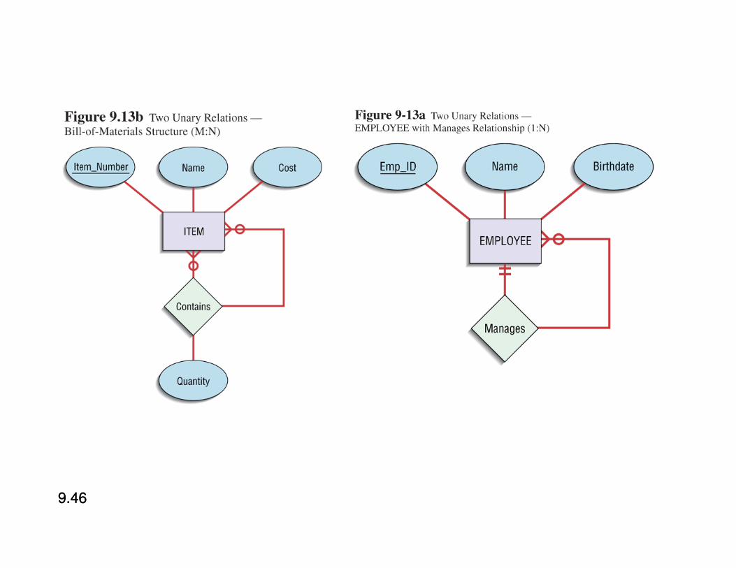
Transforming Unary 1:NRelationships into Relations
• Relationship:
EMPLOYEE (as Manager) Manages EMPLOYEE
• EMPLOYEE Table BEFORE Relationship:
(Emp_ID, Name, Birthday)
• EMPLOYEE Table AFTER Relationship:
(Emp_ID, Name, Birthday, Mgr_ID)
CREATE TABLE EMPLOYEE(
Emp_ID CHAR(1),
Name Varchar(30),
Birthday DATE,
Mgr_ID CHAR(1),
PRIMARY KEY (Emp_ID),
FOREIGN KEY (Mgr_ID)
REFERENCESEMPLOYEE (Emp_ID));

Unary Association Class to Table:CONTAINS
ContainigItem_Number
ContainedItem_Number
Quantity
61384 M128 2
61384 A261 1
62807 A261 2
62807 R149 1
62009 R149 2
Item_Number
Name Cost
A261 Nail 0.99
61384 AAA 21.11
M128 Screw 2.99
62807 BBB 200.11
62009 CCC 99.00
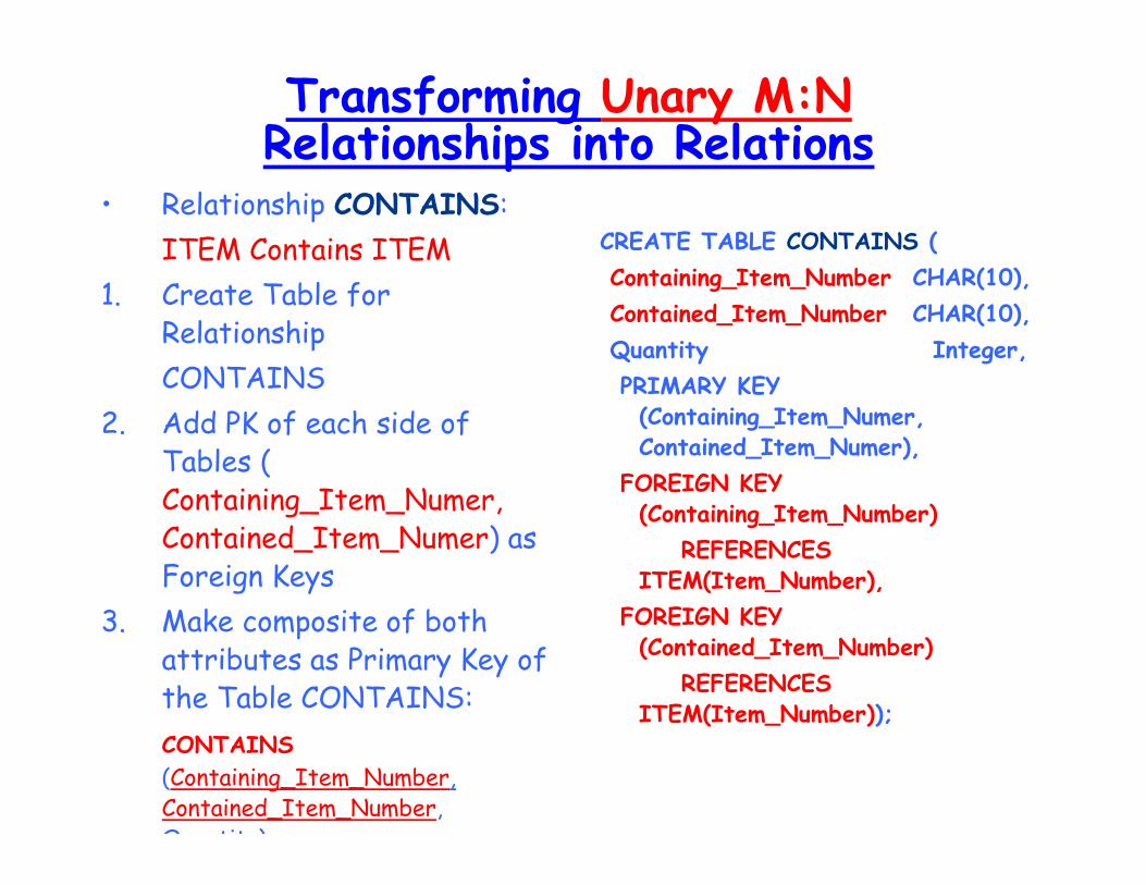
Transforming Unary M:NRelationships into Relations
• Relationship CONTAINS:
ITEM Contains ITEM
1. Create Table for Relationship
CONTAINS
2. Add PK of each side of Tables ( Containing_Item_Numer, Contained_Item_Numer) as Foreign Keys
3. Make composite of both attributes as Primary Key of the Table CONTAINS:
CONTAINS
(Containing_Item_Number, Contained_Item_Number, Quantity)
CREATE TABLE CONTAINS (
Containing_Item_Number CHAR(10),
Contained_Item_Number CHAR(10),
Quantity Integer,
PRIMARY KEY (Containing_Item_Numer, Contained_Item_Numer),
FOREIGN KEY (Containing_Item_Number)
REFERENCES ITEM(Item_Number),
FOREIGN KEY (Contained_Item_Number)
REFERENCES ITEM(Item_Number));
9.519.51
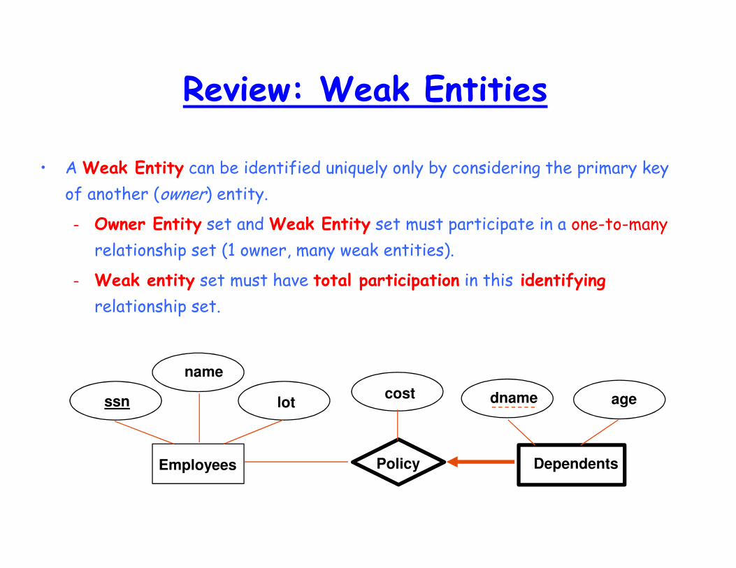
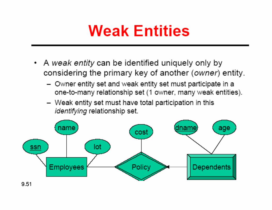
Review: Weak Entities
• A Weak Entity can be identified uniquely only by considering the primary key
of another (owner) entity.
– Owner Entity set and Weak Entity set must participate in a one-to-many
relationship set (1 owner, many weak entities).
– Weak entity set must have total participation in this identifying
relationship set.
lot
name
agedname
DependentsEmployees
ssn
Policy
cost
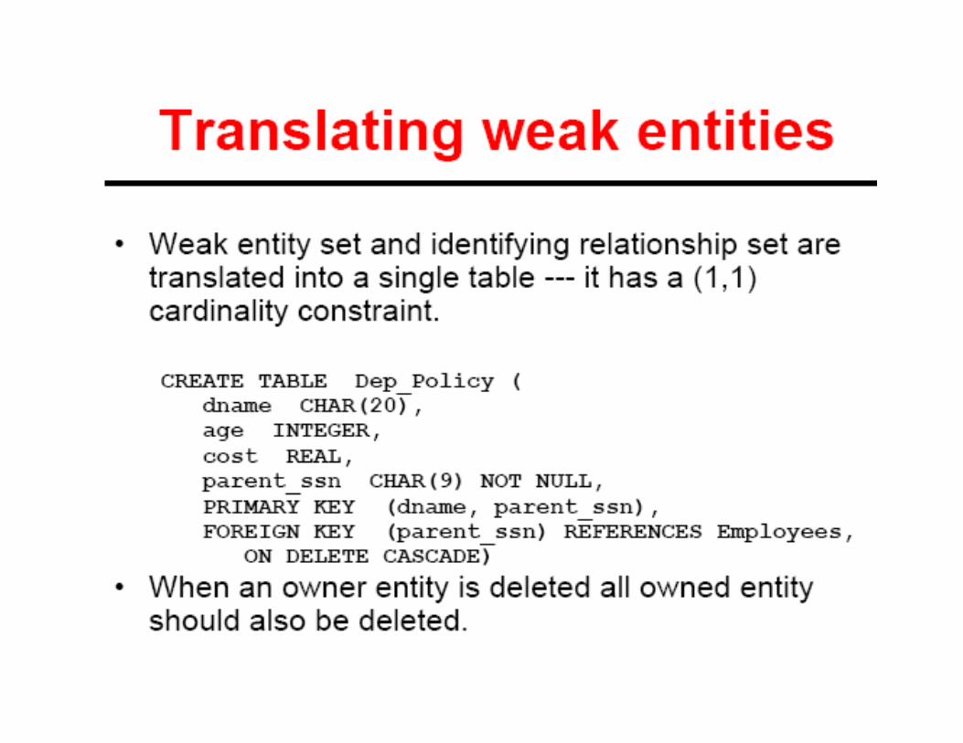
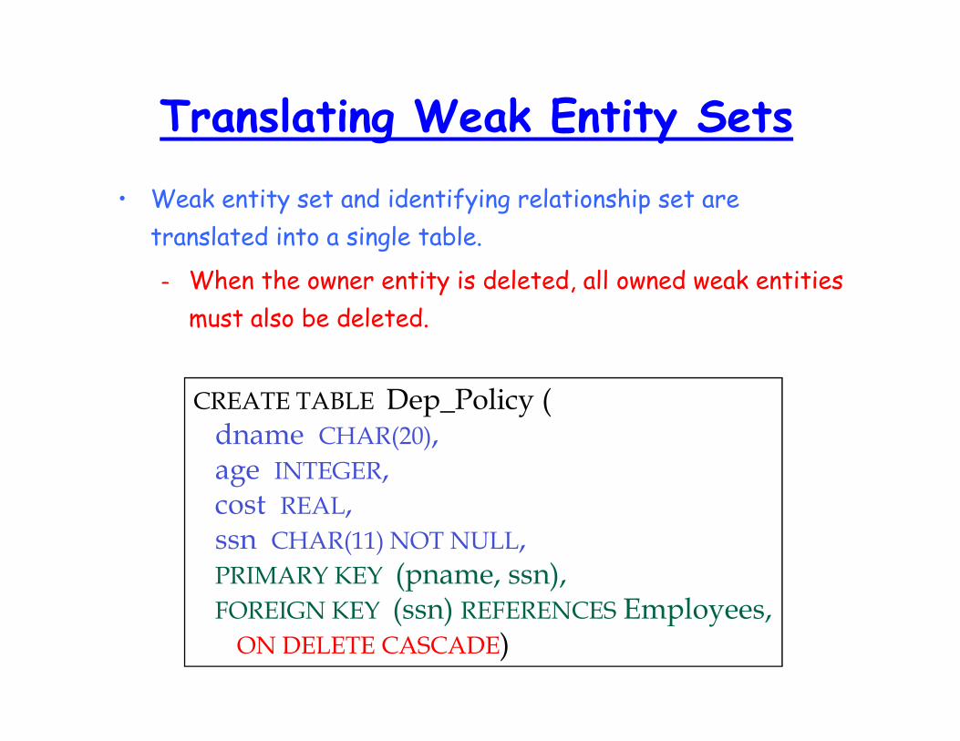
Translating Weak Entity Sets
• Weak entity set and identifying relationship set are
translated into a single table.
– When the owner entity is deleted, all owned weak entities
must also be deleted.
CREATE TABLE Dep_Policy (dname CHAR(20),age INTEGER,cost REAL,ssn CHAR(11) NOT NULL,PRIMARY KEY (pname, ssn),FOREIGN KEY (ssn) REFERENCES Employees,ON DELETE CASCADE)
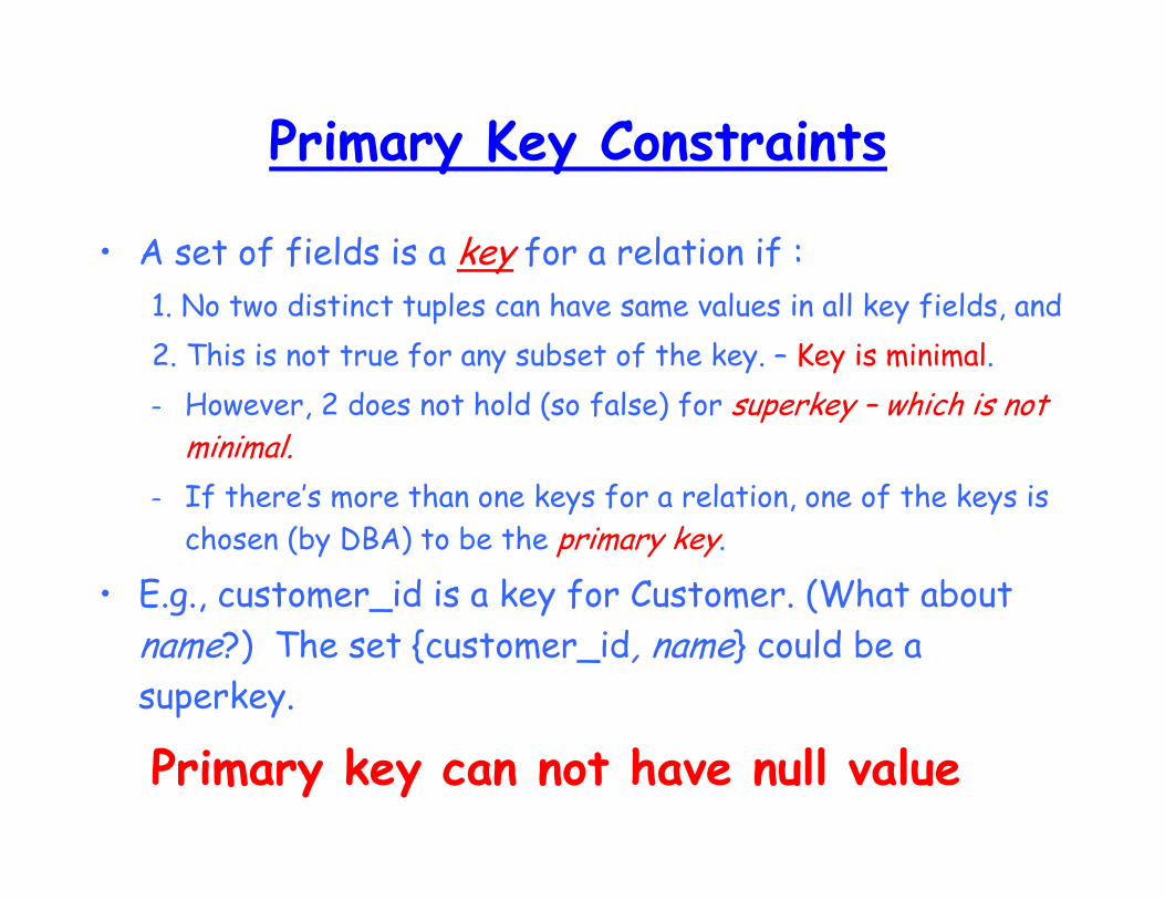
Primary Key Constraints
• A set of fields is a key for a relation if :
1. No two distinct tuples can have same values in all key fields, and
2. This is not true for any subset of the key. – Key is minimal.
– However, 2 does not hold (so false) for superkey – which is not minimal.
– If there’s more than one keys for a relation, one of the keys is
chosen (by DBA) to be the primary key.
• E.g., customer_id is a key for Customer. (What about
name?) The set {customer_id, name} could be a
superkey.
Primary key can not have null value
Domain Constraint
• The value of each Attribute A with
Domain Type D(Ai) must be a atomic value
from the domain type D(Ai).
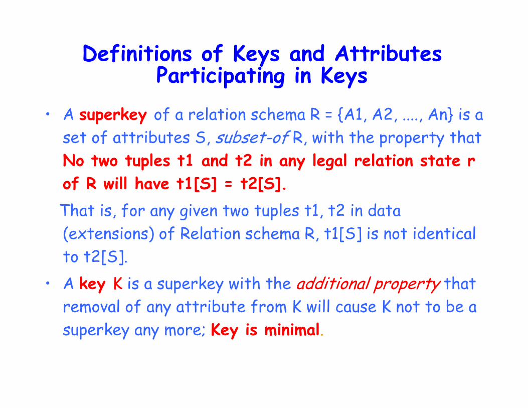
Definitions of Keys and Attributes Participating in Keys
• A superkey of a relation schema R = {A1, A2, ...., An} is a
set of attributes S, subset-of R, with the property that
No two tuples t1 and t2 in any legal relation state r
of R will have t1[S] = t2[S].
That is, for any given two tuples t1, t2 in data
(extensions) of Relation schema R, t1[S] is not identical
to t2[S].
• A key K is a superkey with the additional property that
removal of any attribute from K will cause K not to be a
superkey any more; Key is minimal.
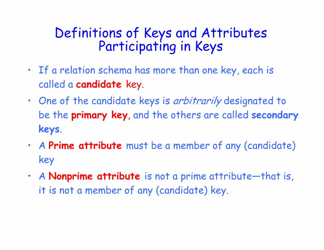
Definitions of Keys and Attributes Participating in Keys
• If a relation schema has more than one key, each is
called a candidate key.
• One of the candidate keys is arbitrarily designated to
be the primary key, and the others are called secondary
keys.
• A Prime attribute must be a member of any (candidate)
key
• A Nonprime attribute is not a prime attribute—that is,
it is not a member of any (candidate) key.
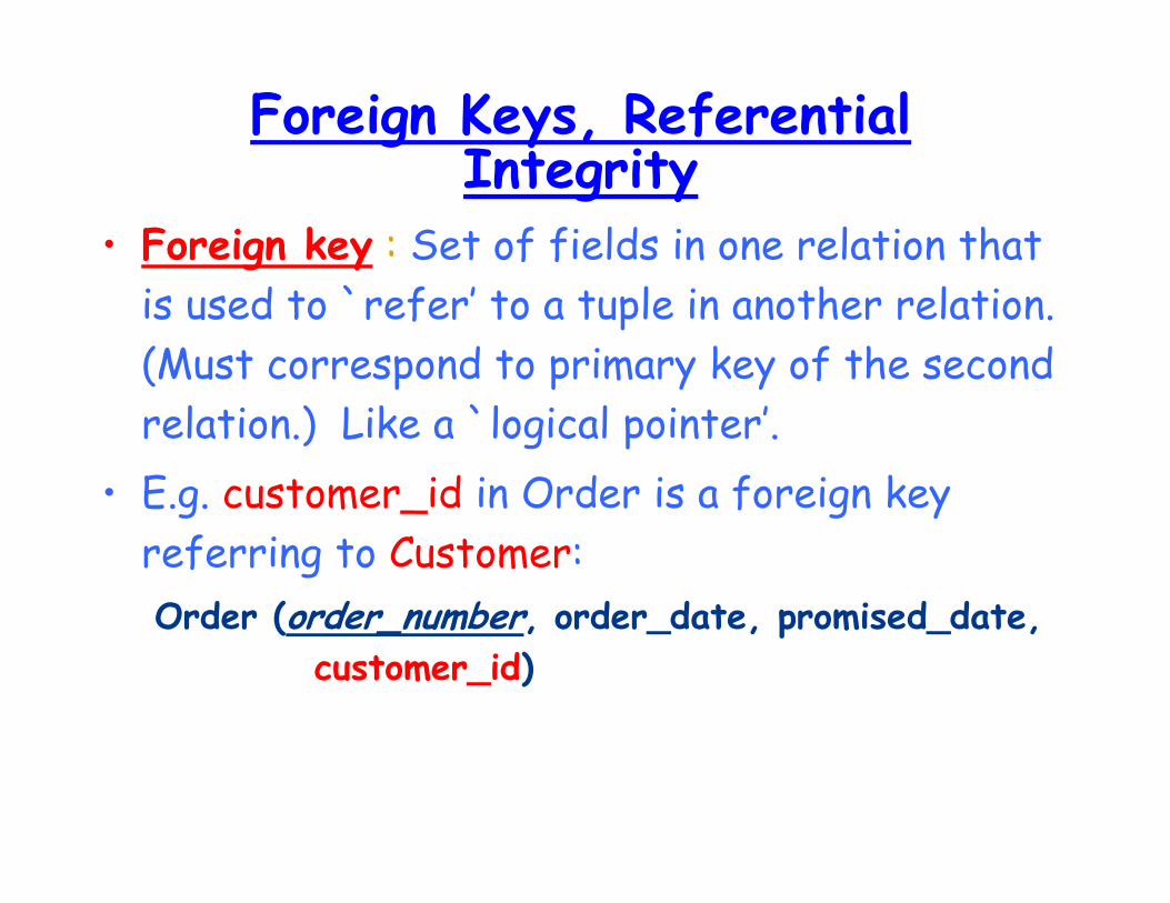
Foreign Keys, Referential Integrity
• Foreign key : Set of fields in one relation that
is used to `refer’ to a tuple in another relation.
(Must correspond to primary key of the second
relation.) Like a `logical pointer’.
• E.g. customer_id in Order is a foreign key
referring to Customer:
Order (order_number, order_date, promised_date, customer_id)
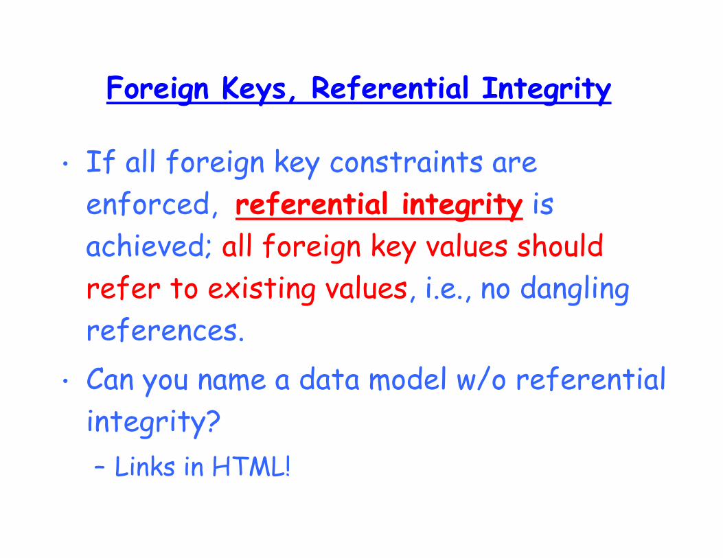
Foreign Keys, Referential Integrity
• If all foreign key constraints are
enforced, referential integrity is
achieved; all foreign key values should
refer to existing values, i.e., no dangling
references.
• Can you name a data model w/o referential
integrity?
– Links in HTML!
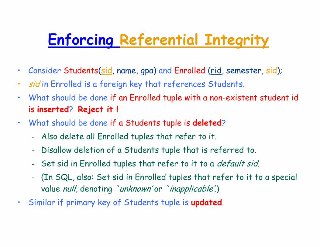
Enforcing Referential Integrity
• Consider Students(sid, name, gpa) and Enrolled (rid, semester, sid);
• sid in Enrolled is a foreign key that references Students.
• What should be done if an Enrolled tuple with a non-existent student id
is inserted? Reject it !
• What should be done if a Students tuple is deleted?
– Also delete all Enrolled tuples that refer to it.
– Disallow deletion of a Students tuple that is referred to.
– Set sid in Enrolled tuples that refer to it to a default sid.
– (In SQL, also: Set sid in Enrolled tuples that refer to it to a special
value null, denoting `unknown’ or `inapplicable’.)
• Similar if primary key of Students tuple is updated.
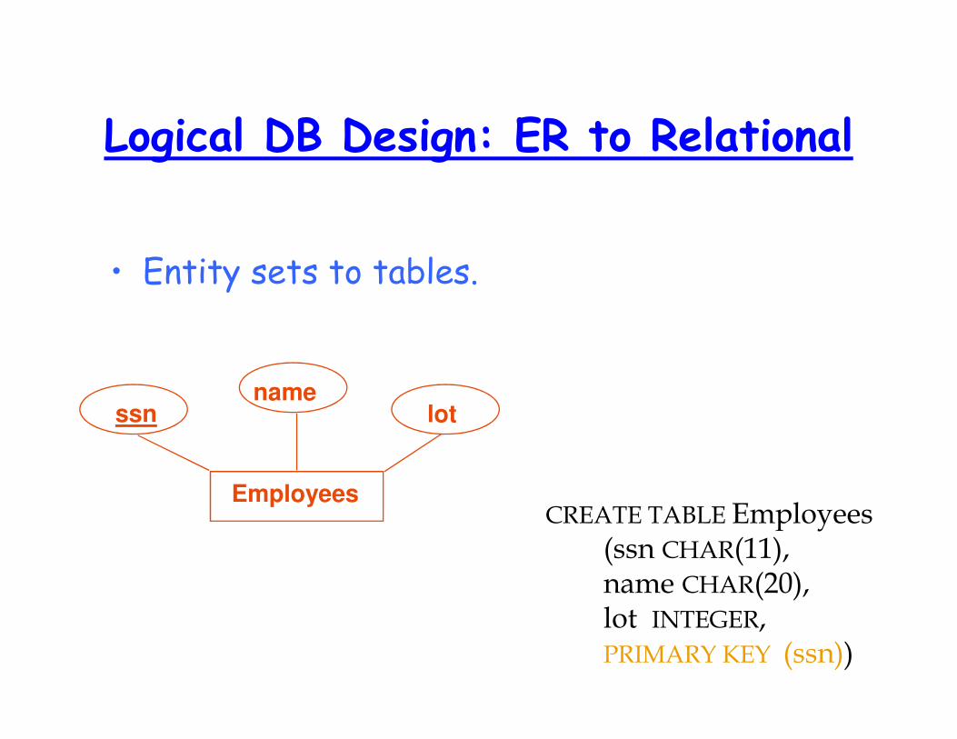
Logical DB Design: ER to Relational
• Entity sets to tables.
CREATE TABLE Employees (ssn CHAR(11),name CHAR(20),lot INTEGER,PRIMARY KEY (ssn))
Employees
ssnname
lot
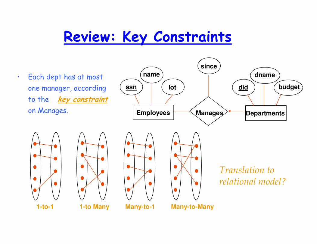
Review: Key Constraints
• Each dept has at most
one manager, according
to the key constraint
on Manages.
Translation to
relational model?
Many-to-Many1-to-1 1-to Many Many-to-1
dname
budgetdid
since
lot
name
ssn
ManagesEmployees Departments
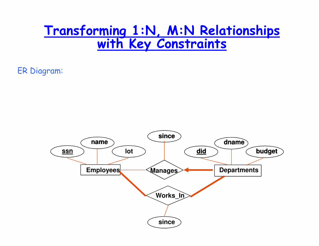
Transforming 1:N, M:N Relationships with Key Constraints
ER Diagram:
lot
name dname
budgetdid
sincename dname
budgetdid
since
Manages
since
DepartmentsEmployees
ssn
Works_In

Translating ER Diagrams with Key Constraints
• Map relationship to a
table:
– Note that did is the
key here!
– Separate tables for
Employees and
Departments.
• Since each department
has a unique manager,
we could instead
combine Manages and
Departments.
CREATE TABLE Manages(ssn CHAR(11),did INTEGER,since DATE,PRIMARY KEY (did),FOREIGN KEY (ssn) REFERENCES Employees,FOREIGN KEY (did) REFERENCES Departments)
CREATE TABLE Dept_Mgr(did INTEGER,dname CHAR(20),budget REAL,ssn CHAR(11),since DATE,PRIMARY KEY (did),FOREIGN KEY (ssn) REFERENCES Employees)
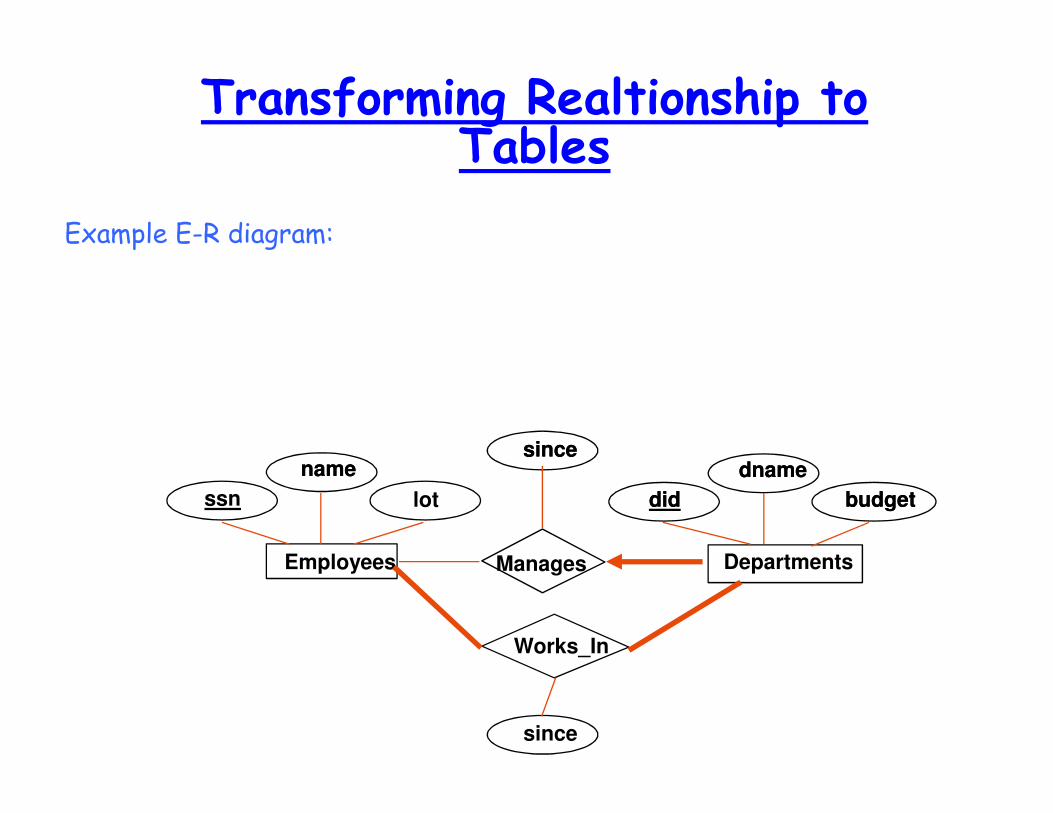
Transforming Realtionship to Tables
Example E-R diagram:
lot
name dname
budgetdid
sincename dname
budgetdid
since
Manages
since
DepartmentsEmployees
ssn
Works_In
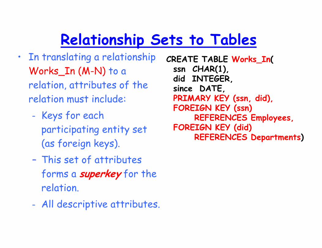
Relationship Sets to Tables• In translating a relationship
Works_In (M-N) to a
relation, attributes of the
relation must include:
– Keys for each
participating entity set
(as foreign keys).
– This set of attributes
forms a superkey for the
relation.
– All descriptive attributes.
CREATE TABLE Works_In(ssn CHAR(1),did INTEGER,since DATE,PRIMARY KEY (ssn, did),FOREIGN KEY (ssn)
REFERENCES Employees,FOREIGN KEY (did)
REFERENCES Departments)
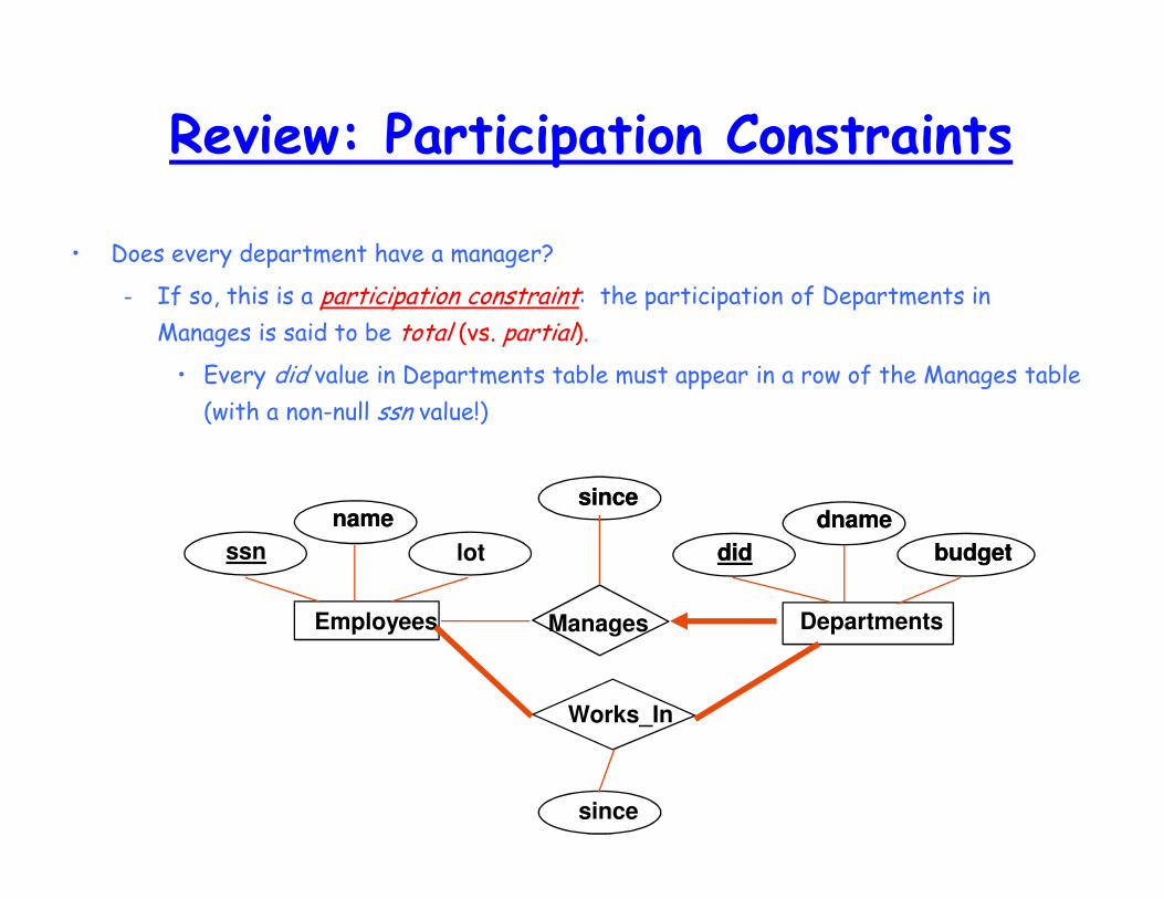
Review: Participation Constraints
• Does every department have a manager?
– If so, this is a participation constraint: the participation of Departments in
Manages is said to be total (vs. partial).
• Every did value in Departments table must appear in a row of the Manages table
(with a non-null ssn value!)
lot
name dname
budgetdid
sincename dname
budgetdid
since
Manages
since
DepartmentsEmployees
ssn
Works_In
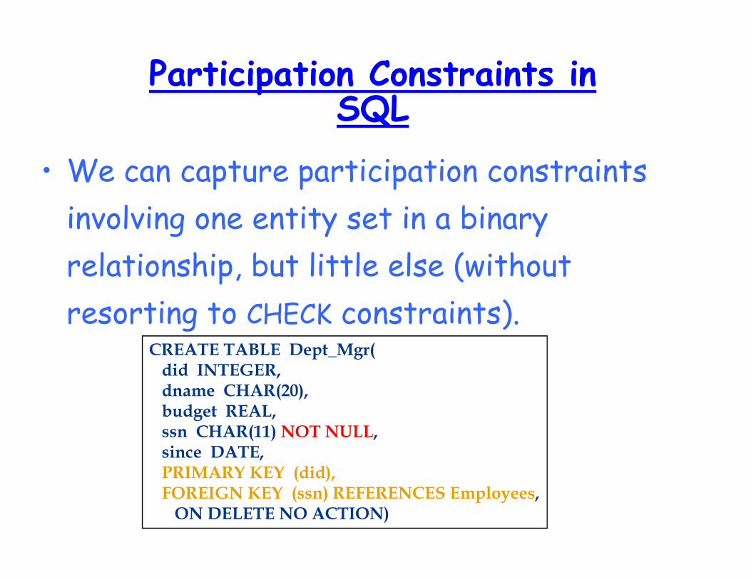
Participation Constraints in SQL
• We can capture participation constraints
involving one entity set in a binary
relationship, but little else (without
resorting to CHECK constraints).CREATE TABLE Dept_Mgr(did INTEGER,dname CHAR(20),budget REAL,ssn CHAR(11) NOT NULL,since DATE,PRIMARY KEY (did),FOREIGN KEY (ssn) REFERENCES Employees,ON DELETE NO ACTION)
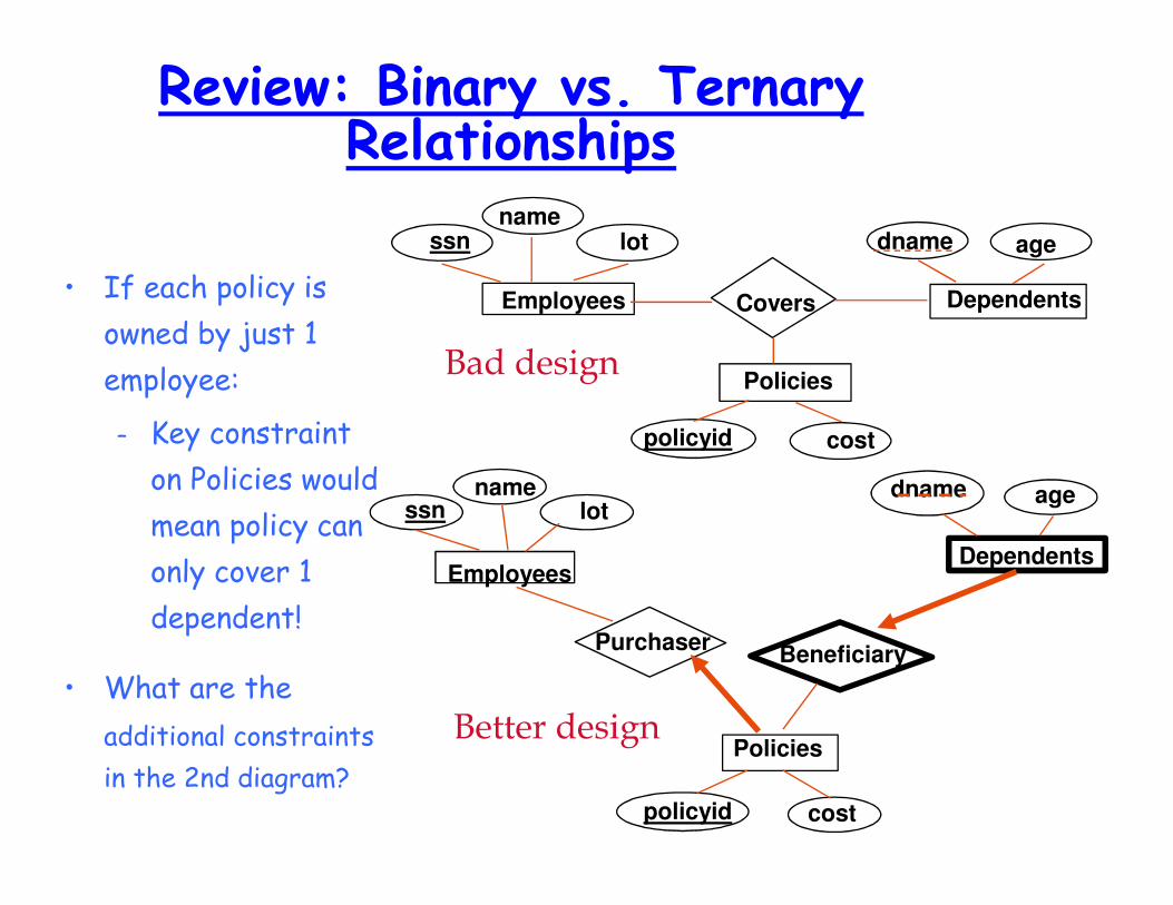
Review: Binary vs. Ternary Relationships
• If each policy is
owned by just 1
employee:
– Key constraint
on Policies would
mean policy can
only cover 1
dependent!
• What are the
additional constraints
in the 2nd diagram?
agedname
DependentsCovers
name
Employees
ssn lot
Policies
policyid cost
Beneficiary
agedname
Dependents
policyid cost
Policies
Purchaser
name
Employees
ssn lot
Bad design
Better design
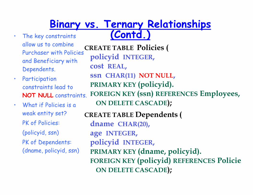
Binary vs. Ternary Relationships (Contd.)• The key constraints
allow us to combine
Purchaser with Policies
and Beneficiary with
Dependents.
• Participation
constraints lead to
NOT NULL constraints.
• What if Policies is a
weak entity set?
PK of Policies:
(policyid, ssn)
PK of Dependents:
(dname, policyid, ssn)
CREATE TABLE Policies (policyid INTEGER,cost REAL,ssn CHAR(11) NOT NULL,PRIMARY KEY (policyid).FOREIGN KEY (ssn) REFERENCES Employees,ON DELETE CASCADE);
CREATE TABLE Dependents (dname CHAR(20),age INTEGER,policyid INTEGER,PRIMARY KEY (dname, policyid).FOREIGN KEY (policyid) REFERENCES PoliciesON DELETE CASCADE);
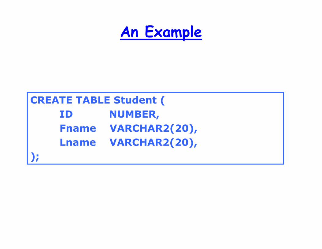
An Example
CREATE TABLE Student (
ID NUMBER,
Fname VARCHAR2(20),
Lname VARCHAR2(20),
);
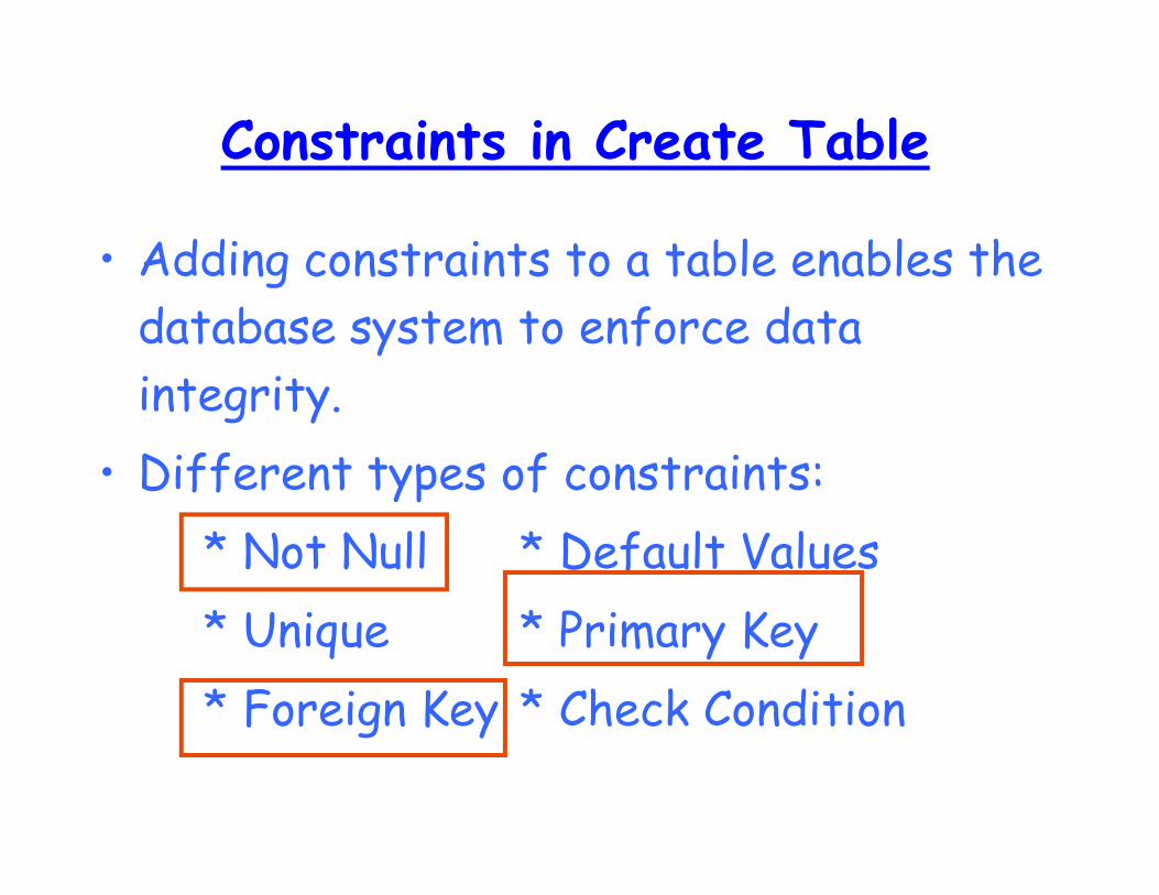
Constraints in Create Table
• Adding constraints to a table enables the
database system to enforce data
integrity.
• Different types of constraints:
* Not Null * Default Values
* Unique * Primary Key
* Foreign Key * Check Condition
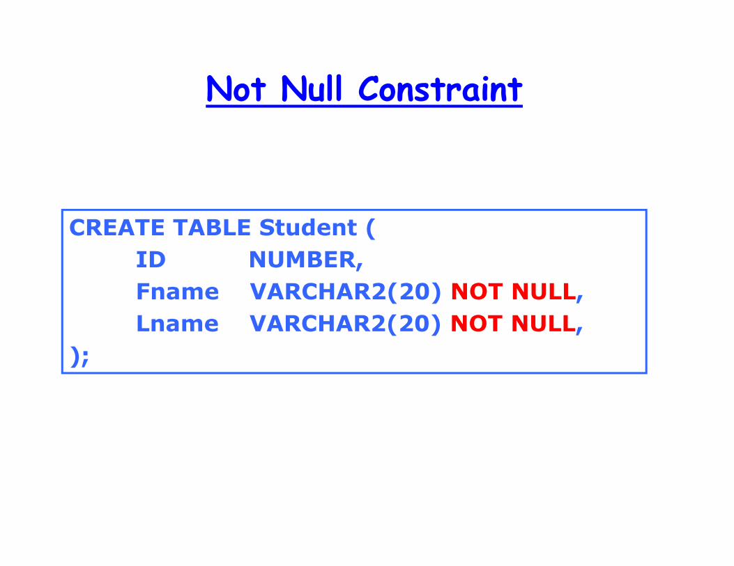
Not Null Constraint
CREATE TABLE Student (
ID NUMBER,
Fname VARCHAR2(20) NOT NULL,
Lname VARCHAR2(20) NOT NULL,
);
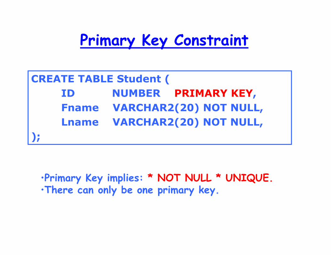
Primary Key Constraint
•Primary Key implies: * NOT NULL * UNIQUE. •There can only be one primary key.
CREATE TABLE Student (
ID NUMBER PRIMARY KEY,
Fname VARCHAR2(20) NOT NULL,
Lname VARCHAR2(20) NOT NULL,
);
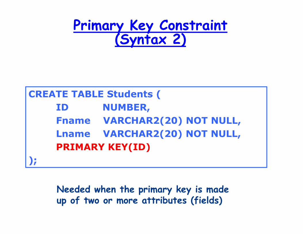
Primary Key Constraint (Syntax 2)
CREATE TABLE Students (
ID NUMBER,
Fname VARCHAR2(20) NOT NULL,
Lname VARCHAR2(20) NOT NULL,
PRIMARY KEY(ID)
);
Needed when the primary key is made up of two or more attributes (fields)
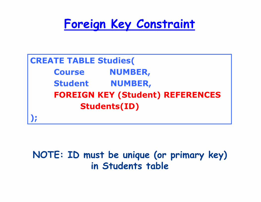
Foreign Key Constraint
NOTE: ID must be unique (or primary key) in Students table
CREATE TABLE Studies(
Course NUMBER,
Student NUMBER,
FOREIGN KEY (Student) REFERENCES
Students(ID)
);


![Extension to SQL: View, Triggers, Transactioncis.csuohio.edu/~sschung/cis430/LectureNote_CIS430_ViewTriggers... · How a view definition is dropped: DROP VIEW ATL-FLT [RESTRICT |CASCADE];](https://img.dokumen.tips/doc/110x75/5f74d6a2468159120007b189/extension-to-sql-view-triggers-sschungcis430lecturenotecis430viewtriggers.jpg)


![Examples o Database Integrity Constraintscis.csuohio.edu/~sschung/cis430/ExampleTest_DatabaseIntegrityConstraints.pdfSsn CHAR (9) NOT NULL, Bdate DATE , [Address] VARCHAR (30 ), Sex](https://img.dokumen.tips/doc/110x75/5f0c08187e708231d433699a/examples-o-database-integrity-sschungcis430exampletestdatabaseintegrityconstraintspdf.jpg)