Embed Size (px)
Citation preview

8/9/2019 Transformer Questions
http://slidepdf.com/reader/full/transformer-questions 1/21
TRANSFORMER QUESTIONS
What Is A Transformer?
A transformer is an electrical device that by electromagnetic induction transforms electric
energy from one or more circuits to one or more other circuits at the same frequency. Byvarying magnetic relationships or values of the input versus the output, a transformer
produces changed values of voltage and current. A transformer works by having the inputwindings made around a core of special steel that conveys the pulses of AC current to
output windings around a core of special steel that conveys the pulses of AC Current to
output windings around the same or connected portions of the steel core.
What is A DC Power Supply?
A DC power supply is a device that will deliver DC voltages and currents to your system.
Most DC power supplies used in the industrial environment will convert the AC power
generated by the utilities to DC power. his is achieved through various rectifierconfigurations.
How Many Types of DC Power Supplies Are Available?
DC power supplies come in many si!es and configurations, but will generally fall into
one of four categories" battery, switch#mode, linear, and regulating. $ach of these devices
has their own unique application benefits and pitfalls. o determine which type of DC power supply is suitable for your application, please contact MA%$&C'(s $ngineering
Department for application service.
What Is An Isolating Transformer?
An isolating transformer is one which insulates the input )primary* from the output)secondary* winding. his can be done by several means, including separating the
windings and for more isolation and shielding.
What Is A Step!own Transformer?
A step#down transformer is one in which the input )primary* windings e+ceed in number
the output )secondary* windings, thus the ratio of voltage is from the high voltagewinding to a low voltage winding or windings. he offset is current, which is higher in
the secondary than it is in the primary.
What Is A Stepup Transformer?
A step#up transformer is one in which the voltage change is from the low voltage windingto a high voltage winding or windings. igh current is used in the primary to produce a
relatively lower current in the secondary.
8/9/2019 Transformer Questions
http://slidepdf.com/reader/full/transformer-questions 2/21
What Is An Auto Transformer?
An auto transformer has its primary and secondary connected to each other electrically. A
portion of the energy in an auto transformer comes from this connection while the balance comes directly from the supply. Building inspectors often ob-ect to auto
transformers because they do not isolate one circuit from the other. 'ne ground may be ata considerably higher voltage than the ground in another section of the same circuit.
&ocal inspectors and utility companies should be consulted before installing autotransformers. here the use of auto transformers is not ob-ectionable, they do represent a
considerable saving in price over that of a regular separate winding transformer. his
saving varies as the ratio of windings changes. After the ratio of windings reachesappro+imately /"0 or 1"0, there is very little economy in using an auto transformer. Auto
transformers are most practical where a small percentage of voltage raising or lowering is
required and isolation between the two circuits is not required. Auto transformers can besingle phase or three phase. 2n neither case is any isolation provided.
What Is "#$iting Current?
$+citing current, when used in connection with transformers, is the current or amperes
required to get the transformer to the point where it will operate. A certain amount of
energy is required to overcome the internal resistance of the steel core. he e+citingcurrent on most transformers varies from appro+imately 034 on small si!es of about 0
56A and smaller to appro+imately .14 to /4 on larger si!es up to 0333 56A. he
e+citing current is made up of two components, one of which is a real component and isin the form of losses or referred to as no#load watts7 the other is in the form of reactive
power and is referred to as 56A%.
What Is %oltage &egulation?
6oltage regulation in transformers is the difference between the no#load voltage and thefull#load voltage. his is usually e+pressed in the terms of percentage" for e+ample, with
a transformer that delivers 033 volts at no#load and 81 volts at full#load, the regulation
would be 14. 9ower and lighting transformers generally have regulation from :4 to /4,
depending on the si!e and the application for which they are used. ;or specialrequirements such as instruments or computers, see the paragraph describing %egulating
ransformers.
What Is Impe!an$e?
2mpedance is the resistance found in all circuits where alternating current is used.$lectrically, impedance is made up of three components# DC resistance, inductance and
capacitance. he inductance and capacitance can be added directly when converted to
like units. 'ne is positive and the other negative. he result of the quantity is then addedvectorally to the resistance. )6ectoral addition is done the same way that sides are added
to a triangle when trying to obtain the hypotenuse.* he impedance of most ordinary
transformers runs between <4 and =4. 6ery low impedance transformers tend to give
8/9/2019 Transformer Questions
http://slidepdf.com/reader/full/transformer-questions 3/21
better regulation. 2f the secondary of the transformer should be accidentally short#
circuited and the impedance of the transformer is low, there would be a very high current
flow on both the primary and secondary windings. his may cause mechanicaldisplacement of the windings and a short circuit between ad-acent turns. ith a
transformer that had an impedance of 14 and the secondary short circuited, the primary
and secondary current would automatically limited to :3+ normal current. 2f theimpedance was 034 the primary and secondary current would be limited to 03+ normal
current, and so on within certain limits that need not be e+plained here.
How Mu$h Power Does A Transformer Consume When I!le?
All transformers consume power when they are connected to a line and there is no#loadconnected to the secondary. his amount of power is very small in comparison to the
56A rating of the transformer. his power consumed is commonly referred to as the no#
load losses. hese losses run on the order of 04 or less for most small and medium si!e
transformers7 for e+ample, a :1 56A, single phase, =3 cycle, />3 volts to 0:3?:/3 volts
transformer would have a no#load loss of about 013 watts or .=4 of the name plate ratingof the transformer. his loss appears in the form of heat and is confined to the iron or
lamination of the transformer. @uch loss relates to the level of e+citing current necessaryto make the transformer operative.
What Is The "ffi$ien$y 'f A Transformer When (ully )oa!e!?
ransformers are among the most efficient electrical apparatus commercially
manufactured. Most transformers of si!es form 0 56A through 0333 56A will have afull#load efficiency of from 814 to 8>.14. he items which lower the efficiency of a
transformer are losses which appear in the iron and those which appear in the windings.
he iron losses are e+plained in the above question. he losses in the windings are due tothe resistance of the wire. hen current flows through a wire, losses appear in the formof heat -ust the same as when an ordinary electric hot plate is turned on.. he wire used in
quality transformers is generally made of copper. Aluminum is sometimes used in low
quality transformers where life e+pectancy is not important or transformers which onlyhave a constant load. hese metals are among the best commercial metals for conducting
electricity. hey offer the least amount of resistance. herefore, little energy is lost in the
form of heat through the windings. hese losses run on the order of 04 to :4 of the full#load rating. hey vary inversely as the square of the load.
What Is The Soun! )evel of A Dry Type Transformer? What Causes Su$h Soun!?
he sound level of a dry type transformer is the result of the variations of flu+ in the iron
core. his can be due to physical movement of pieces of core or lamination and the
elongation and contraction of iron during each cycle of the alternating current used. he ational $lectrical Manufacturers Association )$MA* has set up the following audible
sound level limits for dry type transformers"
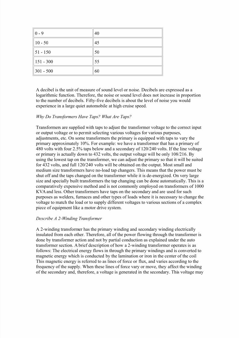
Transformer Rating (KVA) Average Sound eve!s ("e#i$e!s)
8/9/2019 Transformer Questions
http://slidepdf.com/reader/full/transformer-questions 4/21
3 # 8 /3
03 # 13 /1
10 # 013 13
010 # <33 11
<30 # 133 =3
A decibel is the unit of measure of sound level or noise. Decibels are e+pressed as alogarithmic function. herefore, the noise or sound level does not increase in proportion
to the number of decibels. ;ifty#five decibels is about the level of noise you would
e+perience in a large quiet automobile at high cruise speed.
Why Do Transformers Have Taps? What Are Taps?
ransformers are supplied with taps to ad-ust the transformer voltage to the correct input
or output voltage or to permit selecting various voltages for various purposes,
ad-ustments, etc. 'n some transformers the primary is equipped with taps to vary the primary appro+imately 034. ;or e+ample" we have a transformer that has a primary of
/>3 volts with four :.14 taps below and a secondary of 0:3?:/3 volts. 2f the line voltage
or primary is actually down to /<: volts, the output voltage will be only 03>?:0=. By
using the lowest tap on the transformer, we can ad-ust the primary so that it will be suitedfor /<: volts, and full 0:3?:/3 volts will be obtained on the output. Most small and
medium si!e transformers have no#load tap changers. his means that the power must be
shut off and the taps changed on the transformer while it is de#energi!ed. 'n very largesi!e and specially built transformers the tap changing can be done automatically. his is a
comparatively e+pensive method and is not commonly employed on transformers of 0333
56A and less. 'ther transformers have taps on the secondary and are used for such purposes as welders, furnaces and other types of loads where it is necessary to change the
voltage to match the load or to supply different voltages to various sections of a comple+
piece of equipment like a motor drive system.
Des$ribe A *Win!ing Transformer
A :#winding transformer has the primary winding and secondary winding electrically
insulated from each other. herefore, all of the power flowing through the transformer isdone by transformer action and not by partial conduction as e+plained under the auto
transformer section. A brief description of how a :#winding transformer operates is asfollows" he electrical energy flows in through the primary windings and is converted to
magnetic energy which is conducted by the lamination or iron in the center of the coil
his magnetic energy is referred to as lines of force or flu+, and varies according to thefrequency of the supply. hen these lines of force vary or move, they affect the winding
of the secondary and, therefore, a voltage is generated in the secondary. his voltage may
8/9/2019 Transformer Questions
http://slidepdf.com/reader/full/transformer-questions 5/21
be larger or smaller or equal to the input of primary voltage, and is determined by the
ratio of turns between primary and secondary. ;or e+ample, the primary of a transformer
has 033 turns and is connected to 033 volt supply, the secondary has 13 turns, therefore,the secondary voltage will be 13 volts.
Des$ribe A +Win!ing Transformer
A <#winding transformer is identical to a :#winding transformer e+cept that the secondary
has two sections and is quite often suitable for series or parallel. A typical e+ample would be a />3 volt primary with a secondary of 0:3?:/3 volts. indings can be effected by
putting taps at various places on one large winding or by making separate coils )either
primary or secondary*.
Des$ribe A ,Win!ing Transformer
A /#winding transformer is the same as a :#winding transformer e+cept that generally the
primary and secondary are split up into two sections usually suited for series parallelconnection. An e+ample would be a transformer with a primary of :/3?/>3 volts and a
secondary of 0:3?:/3 volts. he voltages indicated are such that the primary can beconnected in series for a />3 volt supply or paralleled for a :/3 volt supply. he
secondary can be in series for :/3 volts or paralleled for 0:3 volts, or connected in series
with the mid tap brought out for 0:3?:/3 volts, < wire operation. his is the mostcommon connection and is found on industrial lighting panels as well as in most
residences.
What Is A Combination Transformer?
2n broad terms, a Combination ransformer is a single device that will take the place oftwo or more transformers or power supplies. A Combination ransformer may be asimple as a single phase single primary voltage )i.e., />3 volt, =3 !. input* with a dual
secondary voltage output )i.e., secondary 0" 0:3 volts 133 6A7 secondary :" :/3
volts 0 56A*, or as comple+ as a three phase multiple primary voltage device withmultiple three phase isolation and auto#transformer outputs, multiple single phase
outputs, and multiple DC voltage outputs.
When Can A Combination Transformer -e .se!?
Enfortunately, there is no cut#and#dried answer to this question. Esually, if you are using
more than one transformer or power supply, a combination transformer may be suitablefor your application. here the combination transformer approach works, the end result
is a smaller, more energy efficient, easier to procure and install, and a less e+pensive
device as compared with a series of single purpose transformers. 9lease consult withMA%$&C'(s $ngineering Department to assist in determining the possible use of
combination transformers in your applications.
What Is The "ffe$t 'f 'ver %oltage or .n!er %oltage 'n The &atings 'f Transformers?
8/9/2019 Transformer Questions
http://slidepdf.com/reader/full/transformer-questions 6/21
ransformers are rated by their 56A capacity. 5 represents kilo or 03337 6 represents
volts7 A represents amperes. he ampere ratings of a transformer are predetermined by
the si!e of 56A. herefore, if the voltage is raised or lowered, the ampere rating mustremain constant, otherwise an e+cess of amperes will cause a higher than planned
temperature rise. An e+ample would be as follows" a 0 56A transformer primary 033
volts7 the primary current would be 03 amps. 2f you apply 83 volts on this transformer,you could not draw more than 03 amperes through the windings without causing
e+cessive heating. ote" when you did so you would cause the 56A to be down to .8
56A. 2f over voltage is used on the transformer, it results in e+cessive core loses and inturn causes the transformer to operate at higher than normal temperature. igh
temperatures tend to shorten the life of a transformer and an appro+imate rule for
estimating the life shortening effect of high temperatures is appro+imately 0?: life for
each 0: degrees centigrade of continuous operation above normal rated temperature.
When A Transformer Is 'perate! At 'ne Half /ormal %oltage0 How Does This Affe$t Its
1%A &ating?
he 56A rating is reduced to one half, or in the same proportion as the voltage, the
secondary voltage is also lowered proportionally.
What "ffe$t Will 23 Cy$le %oltage Have 'n A Transformer &ate! (or 43 Cy$les 'f )i5e%oltage?
he effect will be higher no#load losses or iron losses, which in turn will tend to raise the
temperature of the transformer. Many small types of transformers are rated for 13?=3cycles. his can be done quite successfully, as the amount of heat can be dissipated from
small transformers without too much difficulty. Fenerally speaking, larger si!es of
transformers that are designed in any si!e to operate satisfactorily on both 13 cycles and=3 cycles supplied with like voltages by simply designing the iron core to accept thehigher no#load losses of 13 cycle current. ;ifty cycle transformers will operate very
satisfactorily on a =3 cycle supply with a like voltage. A 13?=3 cycle transformer will cost
between 14 and 034 more than the corresponding =3 cycle transformer.
What "ffe$t Will A 23 Cy$le Supply %oltage Whi$h Is 264 'f The /ormal $y$le %oltage Have .pon The &ating 'f A Transformer?
he 56A rating of the transformer will be lowered in the same proportion as the supply
voltage. 2n this case the 56A rating would be 1?=? of the normal =3 cycle nameplate
rating. %efer back to A 2@ $ $;;$C '; '6$% 6'&AF$ '% ED$%6'&AF$ ' $ %A2F@ '; %A@;'%M$%@ and remember the importance of
ampere load in transformer heating.
How Can 7ou Tell The "#a$t )oa! 'f A Single Phase Transformer Whi$h Is Supplying a+ Wire Cir$uit -y .se of An Ammeter?
8/9/2019 Transformer Questions
http://slidepdf.com/reader/full/transformer-questions 7/21
hen checking the loading of a transformer with an ammeter, all that needs to be known
is the amount of amperes flowing in each of the outside legs or hot wires. Gou do not
have to measure the amount of amperes flowing in the neutral or grounded wire, but youhave to know the voltage from each of the hot wires or outside wires to neutral. An
e+ample of this is a < wire lighting panel 0:3?:/3 volts. he ammeter readings for each
of the outside wires are 13 amps and <3 amps. &et us assume that the transformersupplying this < wire power is a 03 56A 0:3?:/3, < wire secondary. o check the load,
multiply the ampere reading by the voltage from the line to neutral and divide by 0333.
he first reading of 0:3 + 13 amps divided by 0333 equals = 56A. he second reading of 0:3 + <3 amps divided by 0333 equals <.= 56A. he total of these two equals 8.= 56A.
he transformer is :34 over#loaded even though the total load is within the transformer(s
rating. he ma+imum current that can be drawn from each hotline is equal to :/3 volts
divided into the 03 56A, or appro+imately /: amps. Gou find that the 0:3 volt windingsupplying the 13 amp load is working much above its rated capacity and will result in
short life of the transformer. 2t is important to check the secondary loading of a
transformer. 2t is important to check the secondary loading of a transformer in addition to
checking the primary loading. ;or this reason MA%$&C' always rates its transformers by the lower of the secondary or the primary 56A capacity rating.
When Can Transformers -e .se! In Parallel?
ransformers can be paralleled when their voltages are equal. 2f the voltages are notequal, the difference between the voltages will result in a net voltage which will cause
current to circulate on the closed network between the two transformers. his will cause
false loading and, if there is enough difference between the two voltages, the transformers
may actually burn out without any useful load being connected to them. 2n order to havetransformers with like voltages share the load proportionately, their impedance(s must be
similar. 2n most commercial installations a tolerance of 034 impedance is permissiblewhen transformers are paralleled. hree phase transformers must have similar angulardisplacement, meaning the phasing must be the same on each transformer.
Des$ribe A + Phase0 , Wire 8roun!e! /eutral System
Many < phase, / wire, grounded neutral systems are :3>G?0:3. he :3> volts is
measured from line to line and is generally used to supply < phase loads such as motors,ovens or other types of loads requiring a fair si!e block of power as well as balanced
loading. he 0:3 volts is obtained from the neutral to any one of the < line leads. his
0:3 volts is a single phase when taken from the neutral to any one line lead. his is an
economical method for obtaining 0:3 volts for lighting, hand tools and other types ofequipment. 2ndustrial installations commonly also use < phase, / wire, />3G?:HH volts.
his is similar to the :3>G?0:3 volts -ust described, the />3 volts being from line to line
and the :HH volts from line to neutral.
When Is A + Phase0 , Wire 8roun!e! /eutral System Superior To A + Phase0 + WireSystem?
8/9/2019 Transformer Questions
http://slidepdf.com/reader/full/transformer-questions 8/21
he / wire approach is considered to be the safer and more utilitarian. hen standard
0:3 volt lights and other 0:3 volt equipment are used, the fourth wire on the :3> volt, /
wire system offers a convenient method for obtaining this 0:3 volts. he :3>G, < phase, /wire system offers a safety advantage over the < wire, :/3 volt system. 2n the / wire
system, the ma+imum for good safety precautions. 'n the < phase, < wire, :/3 volt
system, generally one corner of the delta is grounded, which leaves the other : line leads:/3 volts above ground. hat(s a helluva lot more -uice than 0:3 volts.
What Is A Delta Conne$tion?
A delta connection is a term used for describing the connections used on < phase
transformers, or < single phase transformers when connected to a < phase supply)sometimes referred to as closed delta connections*. he connection used is very similar
to an equilateral triangle or the symbol delta. each single phase transformer is represented
by one side of the delta or equilateral triangle. he three transformers are connected
together at the corners of the delta. he supply lines or load lines are also connected at
the same -unctions from each corner. his results in a < wire, < phase system.
What Is An 'pen Delta Conne$tion?
his is a term used for describing the connection of two single phase transformers for use
in a < phase power supply for transforming a < phase voltage. he open delta is the sameas the closed delta described above e+cept that one transformer is removed from the
closed delta circuit. 'pen delta is less e+pensive but it presents certain limitations as
compared with normal < phase connections.
What Per$entage 'f Total Transformer Capa$ity Is Available In An 'pen Delta System?
he < phase capacity of an open delta system is >H4 of the total transformers in thecircuit. An e+ample would be" two 13 56A single phase transformers connected in open
delta. he < phase capacity would be the sum of the two units multiplied by .>H or 033
56A + .>H which would equal >H 56A. 2n the event the third transformer of 13 56A wasadded to this open delta bank to form a closed delta, the < phase capacity would then be
the sum of the three transformers in the bank or 013 56A.
What Is The &elationship 'f 979 To Delta?
he terms G and delta are used to describe the connections on transformers when used
on < phase. A G connection is made by connecting the finishes of the primaries orsecondaries of three single phase transformers into a common bank. he starts or other
end of the windings will then connect to the < line leads of the < phase supply. @hould the
fourth wire be available on the < phase system, this would be connected to the common -unction or their center of the G. hen the connections drawn out schematically, it
resembles the capital G. ransformers connected in G will operate at a higher < phase
voltage than their single phase rating. ;or e+ample, transformers with 0:3 volts, single phase windings may be connected in G for :3> volts, < phase. he delta connection is

8/9/2019 Transformer Questions
http://slidepdf.com/reader/full/transformer-questions 9/21
used for connecting < single phase transformers for < phase operation. $ach side of the
delta would represent one winding of each transformer. he < corners of the delta are
then connected to the < phase supply or load. A delta connection does not offer a way tomake a fourth wire connection. Also, the single phase voltages and < phase voltages of a
transformer are alike when the are used on the delta connection. hese delta and G
connections are not necessarily limited to single phase transformers, but apply equallywell on connections of coils on a < phase transformer.
Why Can:t Transformers Conne$te! To Different Phases 'f A + Phase System -e
'perate! in Parallel?
9arallel operation of transformers of different phases, even if they are of like voltages, isnot possible due to the fact that there would be a large circulating current flowing within
the parallel circuit. his is because the instantaneous phase voltages occur at different
times.
Why Is It /e$essary To .se A + Phase Transformer When 8oing (rom + Phase To Single Phase?
@ingle phase is obtained from a < phase system by simply connecting to any two wires in
the < phase system. his applies to a < phase system whether it is < phase?< wire or <
phase?/ wire. 'nce single phase is obtained as e+plained above, then only a single phasetransformer is required. ransformers cannot be used to even out a single phase load so
that it will be distributed equally on all < phases of a < phase system. ransformers may
be used to change any number of phases to any other number of phases other than one.
Are Some + Phase Transformers 9T9 Conne$te!?
connection of < phase transformers is commonly used on small si!es up through 856A )or 01 56A < phase*. A connection is made up of two single phase transformers
connected in a manner resembling the capital . his system usually results in a smaller
and lighter package than if < coils and cores are used in the above#mentioned 56Aratings.
What Does 9S$ott T Conne$tion9 Mean?
@cott connection of transformers is a method used for changing < phase to : phase or
vice versa. he name originates from the man who developed it. his connection consists
of two transformers" one with a center tap called the main and one with an >=.=4 tapcalled the teaser. he teaser is connected to the center tap of the main, and the start and
finish of the main and >=.=4 tap are all connected to the < wires of a < phase supply. he
secondary on the teaser and the secondary on the main each produce a voltage which is83 degrees electrically from each other. hese two voltages make up the : phase. here
are other connections used to obtain : phase from < phase and vice versa, but the @cott
connection is the most economical. 9hase changing transformers can be built in autotypes as well as isolating types.
8/9/2019 Transformer Questions
http://slidepdf.com/reader/full/transformer-questions 10/21
Des$ribe A 4 Phase Star Transformer?
A = phase star system produces a much lower ripple or wave effect than a < phase
transformer. here a < phase transformer has the starts or finishes of each coil connected,with the opposite end to the load, a = phase star each coil is center tapped and the center
taps are connected. his leaves double the number of ends )i.e., =* to be connected to theload. $ach end is thus 0>3 degrees out of phase with its corresponding end on the same
coil. As a consequence there is more overlap of phases, hence less ripple. 2n both < phaseand = phase, obviously, the neutral is brought out for the other side of the load. @i+ phase
star coils must have double the number of turns of a < phase with same line# volts, so
the = phase transformer will be more costly. But this higher cost often can be offset bysavings in the drive motor and controls. 2t is also a good way to optimi!e overall system
cost in many cases where a very high quality rectified current is required.
What Is A ;ig<ag Transformer?
A !ig!ag transformer is used in connection with < phase and is made up of = coilsconnected in a G manner. $ach leg of the G is made up of a coil on a different phase
leg of the transformer. he neutral formed by the !ig!ag connection is very stable.
herefore, this type of transformer, or in some cases an auto transformer, lends itself very
well for establishing a neutral for an ungrounded < phase system. Many times this type of transformer or auto transformer, lends itself very well for establishing a neutral for an
ungrounded < phase system. Many times this type of transformer or auto transformer will
carry a fairly large rating, yet physically be relatively small. his particularly applies inconnection with grounding applications. he reason for this small si!e in relation to the
nameplate 56A rating is due to the fact that many types of grounding auto transformers
are rated for : seconds. his is based on the time to operate an overcurrent protection
device such as a breaker. Iig!ag transformers used to be employed to enable si!ereductions in drive motor systems due to the stable wave form they present. 'ther means
are now more common, such as = phase star.
Can + Phase Power -e 'btaine! (rom A Single Phase Sour$e?
2t is not possible to obtain < phase power from a single phase source by the use oftransformer. ransformers can be used for changing : phase power or any other number
of phases greater than one to any other number of phases including one. ;or e+ample,
you can use a transformer to change : phase to < phase, or even = phase, or 0: phase.'nce power is down to single phase, it can no longer be changed back to multi#phase by
use of transformers. here are limited methods for changing single phase to < phase. he
more common are as follows" operate a < phase motor from a single phase power supplyand take off < phase from the motor terminals. he power obtained by this method is
about :34 of the nameplate rating on the motor. Also, the output voltages are
appro+imately 034 to :34 unbalanced. owever, this is a very economical way ofobtaining < phase power from single phase. 'ther methods commonly employed are
phase shifting devices such as reactors and capacitors. hese devices work quite well
where the load remains nearly constant.
8/9/2019 Transformer Questions
http://slidepdf.com/reader/full/transformer-questions 11/21
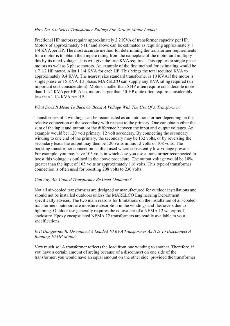
How Do 7ou Sele$t Transformer &atings (or %arious Motor )oa!s?
;ractional 9 motors require appro+imately :.: 56A of transformer capacity per 9.
Motors of appro+imately 1 9 and above can be estimated as requiring appro+imately 00?/ 56A per 9. he most accurate method for determining the transformer requirements
for a motor is to obtain the ampere rating from the nameplate of the motor and multiplythis by its rated voltage. his will give the true 56A required. his applies to single phase
motors as well as < phase motors. An e+ample of the first method for estimating would bea H 0?: 9 motor. Allot 0 0?/ 56A for each 9. his brings the total required 56A to
appro+imately 8./ 56A. he nearest si!e standard transformer is 03 56A if the motor is
single phase or 01 56A if < phase. MA%$&C' can supply any 56A rating required )animportant cost consideration*. Motors smaller than 1 9 often require considerable more
than 0 0?/ 56A per 9. Also, motors larger than 13 9 quite often require considerably
less than 0 0?/ 56A per 9.
What Does It Mean To -u$5 'r -oost A %oltage With The .se 'f A Transformer?
ransformers of : windings can be reconnected as an auto transformer depending on the
relative connection of the secondary with respect to the primary. 'ne can obtain ether the
sum of the input and output, or the difference between the input and output voltages. An
e+ample would be" 0:3 volt primary, 0: volt secondary. By connecting the secondarywinding to one end of the primary, the secondary may be 0<: volts, or by reversing the
secondary leads the output may then be 0:3 volts minus 0: volts or 03> volts. he
boosting transformer connection is often used where consistently low voltage prevails.;or e+ample, you may have 031 volts in which case you use a transformer reconnected to
boost this voltage as outlined in the above procedure. he output voltage would be 034
greater than the input of 031 volts or appro+imately 00= volts. his type of transformer
connection is often used for boosting :3> volts to :<3 volts.
Can Any AirCoole! Transformer -e .se! 'ut!oors?
ot all air#cooled transformers are designed or manufactured for outdoor installations and
should not be installed outdoors unless the MA%$&C' $ngineering Department
specifically advises. he two main reasons for limitations on the installation of air#cooledtransformers outdoors are moisture absorption in the windings and flashovers due to
lightning. 'utdoor use generally requires the equivalent of a $MA 0: waterproof
enclosure. $po+y encapsulated $MA 0: transformers are readily available to yourspecifications.
Is It Dangerous To Dis$onne$t A )oa!e! =3 1%A Transformer As It Is To Dis$onne$t A
&unning =3 HP Motor?
6ery much soJ A transformer reflects the load from one winding to another. herefore, ifyou have a certain amount of arcing because of a disconnect on one side of the
transformer, you would have an equal amount on the other side, provided the transformer

8/9/2019 Transformer Questions
http://slidepdf.com/reader/full/transformer-questions 12/21
was a 0"0 ratio. As the voltages increase, energy transfer becomes more of a problem and
the ha!ards to you and your equipment mount accordingly.
How Does A &egulating (erroresonant Transformer Wor5?
%egulating transformers operate on a resonant principle. he resonant network added tothe transformer consists of a capacitor and inductor connected in parallel, which in turn is
connected in series to the load. his type of transformer is generally / or 1 times larger
physically than an equal si!e : winding transformer. he price also, is more than anominal type transformer. ;erroresonant transformers are used in locations where it is
important that there be practically no voltage variation. A typical e+ample of the
regulation of this type of transformer is 04 variation in output against plus?minus :34variation in input. ;erroresonant transformers are commonly used in filaments on
oscillator tubes in radio or similar type circuit, and lamps used for picture development
work where light output is very critical. 'ne of the common ob-ections to this type of
transformer is that the output voltage wave is distorted and resembles a wave with a
square top. here a harmonic free sine wave is required, specify MA%$&C'(s 9&C9rotector C6@ type transformer. hese transformers provide e+cellent regulation and a
harmonic free wave form and are made in a range of si!es for all computer and solid stateapplications.
Why Are (erroresonant Transformers 'versi<e! when Prote$ting Computers0 P)C:s or
C/C:s?
2nherent in the design of ferroresonant transformers is a current limiting characteristic.Current limiting means that the output current will be limited to a predetermined value
regardless of the load demands. his predetermined value is typically 0134 of the full
rated running current. 'ften the power supplies of the computers, 9&C(s and CC(s willdemand a high current surge. his current surge )often termed inrush 6A or inrush Amps*will typically be :334 of the continuous running current. 'bviously, if the ;erroresonant
ransformer has a current limiting value of 0134 of its rated output current, it will not be
able to deliver a :334 current surge if si!ed right at the continuous power level rating.herefore, ferroresonant transformers typically are si!ed with a 6A rating 134 greater
than the loads continuous 6A rating. MA%$&C'(s 9&C 9%'$C'% ferroresonant
transformers are designed to be able to deliver the high current demands mentionedabove so that no 6A oversi!ing needs to be considered upon ordering.
What:s The Problem &egar!ing Current Inrush Prote$tion In P)C:s?
Conventional surge and noise protection for industrial 9&C(s are not designed for the
current inrush specifications of switch#mode power supplies commonly used in 9&C
applications. Accordingly, when the 9&C is turned on and it operates over its internalcycle, current up to one and one#half times rated levels flow into the system. his can
cause memory losses, data transposition and other problems. MA%$&C' has solved this
problem with its patented 9&C 9%'$C'% system. his is a high quality constantvoltage transformer )specifically designed for current inrush of switch#mode power
8/9/2019 Transformer Questions
http://slidepdf.com/reader/full/transformer-questions 13/21
supplies* and packaged in an industrial quality enclosure. Additionally, M'6(s and !ener
diodes may be added for e+tra protection at a nominal e+tra cost. A wide variety of
optional switches, receptacles, wiring and cabinet choices are also available. he key tothe system is the capacity of the transformer which is designed to be 0 0?: times the rated
capacity, to provide ample reserve for current inrush.
Why Are &esistan$e Wel!ing Transformers Smaller Than &egular AirCoole!
Transformers?
Most resistance welder transformers are smaller than conventional transformers due to
the duty cycle and the method of cooling. 2f a transformer is used less than continuous
duty, the si!e will become appreciably smaller. An e+ample would be using a 0 56Atransformer for < 56A intermittent load. he transformer will operate very satisfactorily
as well as have a long life e+pectancy even though it may be operated at several times its
normal continuous rating. he principal precaution which must be taken into
consideration is temperature rise. he hotter a transformer operates, the shorter the life
e+pectancy of the insulation. @ometimes resistance welding transformers have theappearance of being dry type, yet there are small copper tubes intermingled with the
windings in which water is flowing. ater is a very e+cellent material to absorb heatrapidly, therefore, the heat is dissipated much faster through the water than if air spaces
with fins were used. Development of welding transformers has reached a new high in the
M22#MAK series of transformers designed for placement at the end of a robotic arm dueto their e+tremely light weight for their 56A ratings.
"#plain Why A &e$tifier Transformer May Have Different 1%A &ating 'n The Primary
An! Se$on!ary0 Whereas It Is The .sual A$$epte! (a$t That A Conventional
Transformer Has ">ual &ating 'n The Primary An! Se$on!ary?
he difference in 56A rating on the secondary of rectifier transformers varies dependingon the rectifier circuit used. @ome e+amples are as follows" single phase full wave# the
transformer secondary 56A is appro+imately /34 greater than the primary7 single phase
bridge circuit# the primary and secondary 56A are equal7 < phase half wave# thesecondary is appro+imately ::4 greater than the primary 56A7 < phase full wave
rectifier circuit# the transformer primary and secondary 56A are equal. he reason for
the difference in 56A rating on the secondary compared to the primary of the transformer is due to the irregular wave shape occurring on the secondary. Different types of wave
shapes will cause different amounts of heating. herefore, the windings of the
transformer must be increased to make allowance for this heating effect depending on the
type of rectifier circuit used.
Why Are Some Transformers Woun! With Aluminum Instea! 'f Copper?
his is mostly a matter of economics in which some manufacturers try to cut cost by
reducing quality. An aluminum wire of the same diameter or cross sectional area has only
about =34 of the conducting properties of an equivalent si!e copper wire. owever,aluminum weighs considerably less than copper and if you treat the two metals on a
8/9/2019 Transformer Questions
http://slidepdf.com/reader/full/transformer-questions 14/21
pound versus cubic inch basis, there are about < cubic inches of aluminum for each cubic
inch of copper. @ince both metals are purchased on a cost per pound basis some
manufacturers use aluminum, even though the resulting transformer is substantially larger than a quality copper transformer. ot all types of windings nor all si!es of transformers
lend themselves to be adapted to both aluminum and copper windings. ransformers with
aluminum windings must be oversi!ed to the load and generally have about one fourththe life of a quality copper wound transformer. Aluminum wound transformers perform
best in constant load applications and should not be used for intermittent or varying
loads.
What Is The Signifi$an$e 'f )isting The Primary %oltage 'f A Single Phase Transformeras *,336,=437 %olts?
he :/33 volt indicates the voltage for which the primary is designed7 /0=3G volts
indicates that the insulation is sufficient to permit < of these transformers to be operated
in G on a < phase :/33?/0=3G system.
How Do 7ou Sele$t the Proper Si<e 'f Control Transformer (or .se 'n Control
Devi$es?
he si!e or volt ampere rating of the control transformer is determined by the sum of the
6A requirements for each of the devices to be operated. ;or e+ample, you have a holdingcoil which draws / amperes when the holding coil is in the closed or sealed position. he
voltage on this coil is 0:3 volts. he 6A required would be />3. owever, the inrush
current before the solenoid is closed may be < or / times value, depending on the designof the particular holding device. 'ne must know or determine the inrush current and the
minimum voltage at which the holding device will draw into normal position. As you can
readily see, the 6A requirements or amperes will tend to cause the secondary voltage ofthe transformer to drop below the normal open circuit voltage. 2n order to determine ifthere will be enough voltage present, one should refer to the equipment manufacturer(s
specifications. $nough 56A capacity must be provided to cope with the current inrush of
all devices on the transformer(s secondary circuit.
How Does A Saturable &ea$tor Wor5?
A saturable reactor consists of a coil or winding connected to a DC circuit which is used
to energi!e a core which has an AC coil or winding. As the DC current increases it
reduces the impedance of the core and allows the AC current to pass at a particular point
on the wave. By increasing or decreasing the DC current the AC current can be made toaverage at a desired value. hus, reactors are used to control AC for heavy loads, current
limiting or where great precision is required in an analog mode. %eactors can also be used
in reverse to measure AC current. MA%$&C' has long made a wide range of saturablereactors.
Does The %oltage a$ross The )oa! Whi$h Is Controlle! -y A Saturable &ea$tor %ary
With Different )oa! Power (a$tors?
8/9/2019 Transformer Questions
http://slidepdf.com/reader/full/transformer-questions 15/21
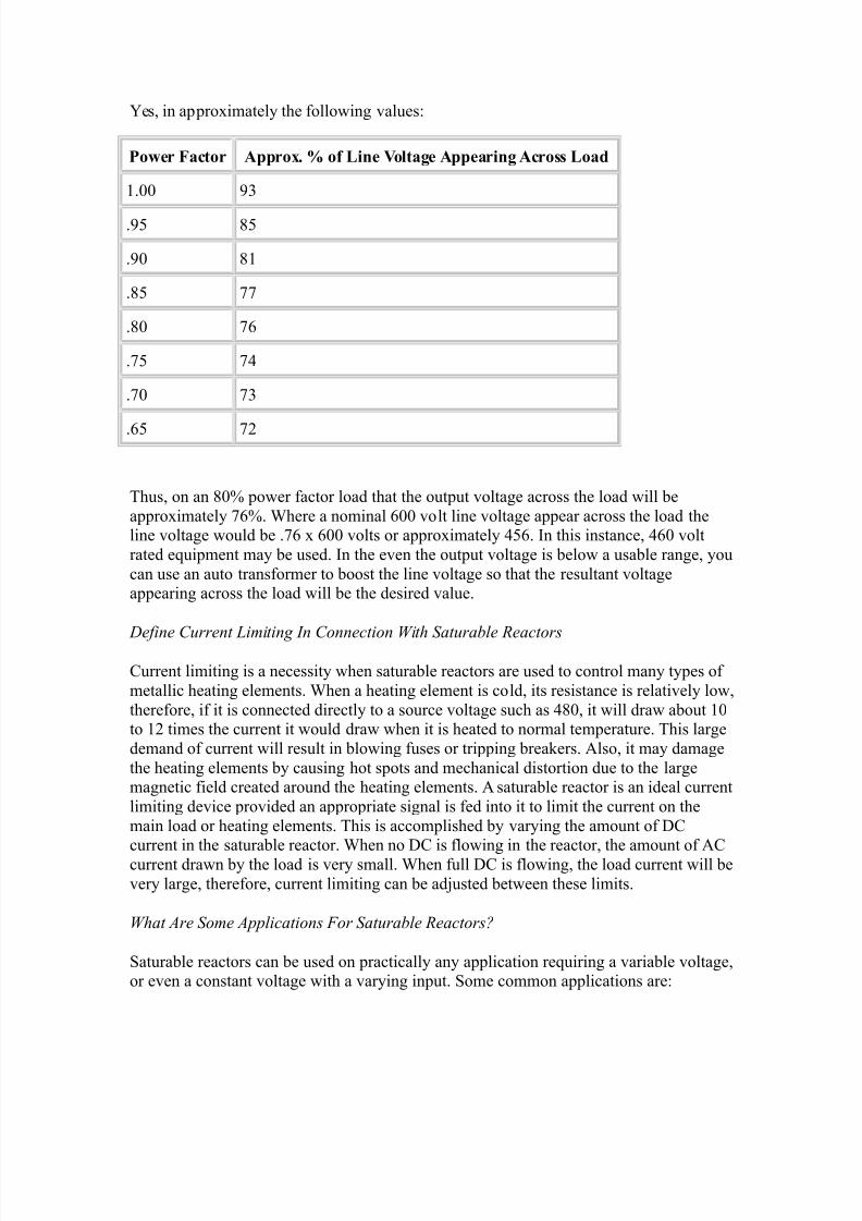
Ges, in appro+imately the following values"
%o&er Fa#tor A''ro * of ine Vo!tage A''earing A#ross oad
0.33 8<
.81 >1
.83 >0
.>1 HH
.>3 H=
.H1 H/
.H3 H<
.=1 H:
hus, on an >34 power factor load that the output voltage across the load will be
appro+imately H=4. here a nominal =33 volt line voltage appear across the load theline voltage would be .H= + =33 volts or appro+imately /1=. 2n this instance, /=3 volt
rated equipment may be used. 2n the even the output voltage is below a usable range, you
can use an auto transformer to boost the line voltage so that the resultant voltageappearing across the load will be the desired value.
Define Current )imiting In Conne$tion With Saturable &ea$tors
Current limiting is a necessity when saturable reactors are used to control many types of
metallic heating elements. hen a heating element is cold, its resistance is relatively low,
therefore, if it is connected directly to a source voltage such as />3, it will draw about 03to 0: times the current it would draw when it is heated to normal temperature. his large
demand of current will result in blowing fuses or tripping breakers. Also, it may damage
the heating elements by causing hot spots and mechanical distortion due to the largemagnetic field created around the heating elements. A saturable reactor is an ideal current
limiting device provided an appropriate signal is fed into it to limit the current on the
main load or heating elements. his is accomplished by varying the amount of DCcurrent in the saturable reactor. hen no DC is flowing in the reactor, the amount of AC
current drawn by the load is very small. hen full DC is flowing, the load current will be
very large, therefore, current limiting can be ad-usted between these limits.
What Are Some Appli$ations (or Saturable &ea$tors?
@aturable reactors can be used on practically any application requiring a variable voltage,or even a constant voltage with a varying input. @ome common applications are"

8/9/2019 Transformer Questions
http://slidepdf.com/reader/full/transformer-questions 16/21
0. Control temperature of ovens or other heating devices
:. Control temperature of molten glass
<. %educe 56A demand of equipment requiring high starting current/. %eversing < phase motors without requiring heavy switches or contactors
1. Motor starting and speed control
=. Maintain a constant current in a loadH. 9roduce variable direct current voltages when used in con-unction with a rectifier
What Is A Motor Drive Transformer?
All of the above descriptions of various rectified output transformers, e.g. < phase, =
phase, etc., describe various types of motor drive transformers. Although they are likedistribution transformers in appearance, motor drive transformers are intended for use in
a rectifying circuit.
What Is A Ma$hine Tool Transformer?
Any piece of equipment having a high current inrush for starting needs some form ofcontrol. his commonly supplied by what is variously called a machine tool transformer
or control transformer )generally those having a 6A rating of :13 or less*. By increasing
the transformers impedance, by design, the current inrush is accommodated while
maintaining a stable secondary voltage.
How Is Duty Cy$le Ta5en Into Consi!eration?
2n many applications, a transformer will not be called upon to provide the ma+imumamount of current required by a system on a continuous basis. Lust like motors which are
rated by a duty cycle calculation, a transformer rated for continuous duty will be biggerand more e+pensive than one rated for partial duty. 2n typical machine tool application,
for e+ample, a duty cycle of 134 is assumed. By calculating the percentage of full#load
use required you can properly si!e both the transformer and motor in a system. hesquare root of the duty cycle times the full#load 56A requirement gives the effective
56A rating required for the transformer. ;or e+ample, take a 134 duty cycle for which
the square root is .H0. hus, the transformer will have to be H04 of the full#load rating.
What Is A Cho5e?
A choke or inductor is a magnetic device which acts as a buffer or pool into which a power surge can be introduced and from which a predetermined flow will be produced. A
choke is basically a single winding transformer. he choke is measured principally by its
current handling capability )like /3 amps*, its inductance )such as : Mhy* and itslinearity )e+pressed as linear up to + times rated capacity*. Chokes permit reducing line
voltage to a given load without substantial power loss. hey are typically used in @C%
drives to modulate the current fed by the drive control system to the motor. Many
8/9/2019 Transformer Questions
http://slidepdf.com/reader/full/transformer-questions 17/21
manufacturers make chokes for use as filters to eliminate stray harmonics. 2n such cases,
current inrush and linearity are not important. But do not simply pick a filter inductor
from a catalog and e+pect it to perform well in a drive system because it has the rightamperage and impedance. 2t may not have the linearity required for smooth performance
at high load. MA%$&C' chokes are specifically designed and tested for linearity and
charts thereof can be produced for your engineering files if you need them.
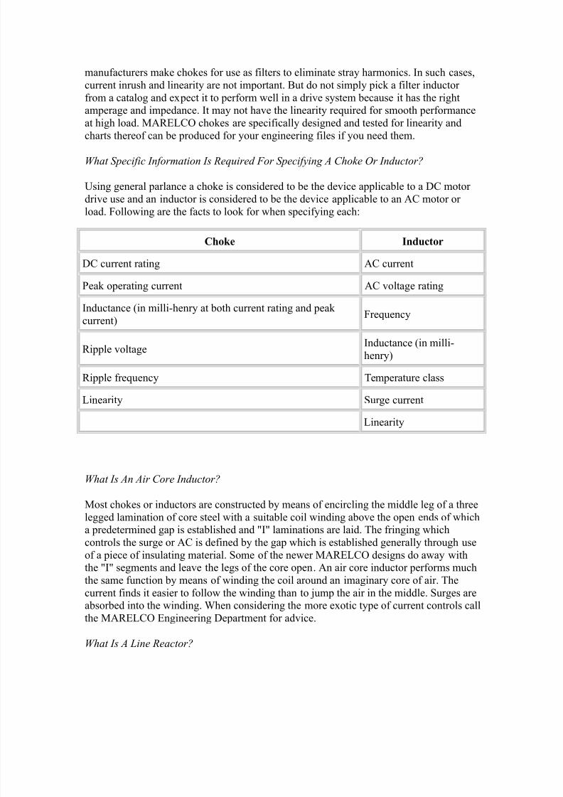
What Spe$ifi$ Information Is &e>uire! (or Spe$ifying A Cho5e 'r In!u$tor?
Esing general parlance a choke is considered to be the device applicable to a DC motor
drive use and an inductor is considered to be the device applicable to an AC motor or
load. ;ollowing are the facts to look for when specifying each"
+,o-e Indu#tor
DC current rating AC current
9eak operating current AC voltage rating
2nductance )in milli#henry at both current rating and peak
current*;requency
%ipple voltage2nductance )in milli#
henry*
%ipple frequency emperature class
&inearity @urge current
&inearity
What Is An Air Core In!u$tor?
Most chokes or inductors are constructed by means of encircling the middle leg of a three
legged lamination of core steel with a suitable coil winding above the open ends of whicha predetermined gap is established and 2 laminations are laid. he fringing which
controls the surge or AC is defined by the gap which is established generally through use
of a piece of insulating material. @ome of the newer MA%$&C' designs do away withthe 2 segments and leave the legs of the core open. An air core inductor performs much
the same function by means of winding the coil around an imaginary core of air. he
current finds it easier to follow the winding than to -ump the air in the middle. @urges areabsorbed into the winding. hen considering the more e+otic type of current controls call
the MA%$&C' $ngineering Department for advice.
What Is A )ine &ea$tor?
8/9/2019 Transformer Questions
http://slidepdf.com/reader/full/transformer-questions 18/21
A line reactor is a special form of inductor that is typically used between the line and the
load to smooth current inrush, reduce harmonics and noise, and buffer the systems
connected to it. @pecifically it is an inductor that adds inductive impedance to a circuit.hese devices are available in either single phase or three phase configuration, with three
phase units being the most common, and are connected in series to the load which they
are protecting. line reactors are typically specified as a percent impedance at a certainvoltage and current level. ;or e+ample, a />3 volt, 14, :1 amp, line reactor is a typical
specification. his specification means that a :1 amp load current the line reactor will
have a 14 inductance impedance voltage drop on a />3 volt system. 2f the load is aninductive impedance load, the voltage to the load will be 14 lower than the voltage to the
line reactor. 2f the load is a capacitance impedance load, the voltage to the load will be
14 greater than the line voltage input to the line reactor. 2f the load is a resistance
impedance load, the load voltage will be less than 04 lower than the voltage input to theline reactor. 'ften line reactors are used in circuits to replace considerably larger and
more e+pensive drive isolation transformers.
When Can A )ine &ea$tor repla$e A Drive Isolation Transformer?
A line reactor can usually replace a drive isolation transformer when the intended purposeof the drive transformer is noise attenuation on the load or line circuit. &ine reactors and
drive isolation transformers are two#way devices" high frequency spikes or notched
generated on either the line input or by the load output will be attenuated before reachingthe load output or line input, respectively. 2n fact, a line reactor will typically do a better
-ob of noise attenuation than a drive isolation transformer because it is a nearly pure
inductive impedance device. he impedance of the drive isolation transformer is a
function of the resistive and inductive impedance components. 2t is the inductivecomponent of the impedance that plays the role in noise attenuation. A 14 impedance
line reactor will typically have a greater inductive impedance component than a 14impedance drive isolation transformer. An iron core line reactor may not be an acceptablesubstitute for a drive isolation transformer if the purpose of the device is to limit fault
currents to the output circuit. An iron core line reactor will have a much higher fault
current pass through characteristic than the comparable drive isolation transformer.owever, for most systems =33 volts or less, this is typically a non#issue. 2f fault currents
are an issue, air core line reactors may be utili!ed in the system. Air core line reactors
will be larger and more e+pensive than iron core equivalents, but will still be lesse+pensive and smaller than a drive isolation transformer. Air core line reactors are mostly
used in systems that have line voltages higher than 01 56.
Can A )ine &ea$tor -e .se! To Convert %oltage? i@e@ from a ??? %olt Input To A *+3
%olt 'utput?
A line reactor is not a voltage converting device. %emember, the line reactor outputvoltage will be nearly equal to the line reactor input voltage. owever, a line reactor may
by packaged with an auto#transformer to achieve the same voltage conversion and
impedance characteristics as a drive isolation transformer. he line reactor ? auto#
8/9/2019 Transformer Questions
http://slidepdf.com/reader/full/transformer-questions 19/21
transformer package will be about :1#<34 smaller and maybe less e+pensive than the
comparable drive isolation transformer.
What Is A Harmoni$ (ilter In!u$tor?
A harmonic filter inductor is a speciali!ed inductor that is used in con-unction with power factor correcting capacitors. he harmonic filter inductor, when connected in series with
the power factor correcting capacitors, will make a tuned &C filter at a specified
frequency. his &C filter network can then be used to either filter out unwanted damagingharmonic currents, or set up as a de#tuned system to prevent parallel resonance between
the power factor correcting capacitors and the inductive impedances on the power
system.
How Do Harmoni$ (ilter In!u$tors Differ (rom 9Stan!ar!9 In!u$tors An! &ea$tors?
here are three ma-or differences between harmonic filter inductors and standard
inductors or line reactors. hese differences are"
0. ighter 2nductance olerance
hen the harmonic filter inductor is used in a detuned circuit, or a filter circuit,the inductance value is very critical to the correct operation of the system.
armonic filter inductors need inductance tolerances no great than ?# 14, and
under some instances as tight as ?#:4 or less. @tandard inductors will have
inductance tolerances of ?# 034.:. Multiple ;requency Current @pectrum %atings
ypically, harmonic filter inductors have multiple frequencies of current flowing
through them simultaneously. $ach of these currents, at their respective frequency,
contribute to the heating effects on the inductor. A standard inductor such as a linereactor, has a current rating assigned to it that is determined at a single frequency
only. More often than not, the heating effect of the multiple frequency currents, ismuch greater than the heating effect of a single frequency current. he harmonic
current responsible for heating )i.e., thermal current* is calculated by using the
square root of the sum of the squares. hese currents are determined from the
harmonic current spectrum. ypically harmonic currents can be 134 or more thana single frequency current seen be a standard line reactor. A single frequency
thermal current rating, even though equal to a thermal current rating by the sum of
the squares method has significantly less heating characteristics.<. &onger Designed &ife $+pectancy
&onger life e+pectancy is both a system characteristic and a customer requirement
in harmonics suppression. Due to the heating characteristics of harmonic currents,it is necessary to be able to design and manufacture equipment targeted at the
specific application and harmonic current frequencies generated. Because of our
wide e+perience in the field, MA%$&C' has developed unique knowledge ofharmonic filter inductor design. his permits us to design and manufacture
harmonic filter inductors with a life e+pectancy of :1 years or more.
8/9/2019 Transformer Questions
http://slidepdf.com/reader/full/transformer-questions 20/21
What Is A Motor Starting &ea$tor?
A motor starting reactor is basically a form of inductor specifically designed for a
particular motor situation to eliminate torque damage, reduce voltage drop and cushionthe start of an AC motor. @ince the < phase induction motors can draw up to =334 of
rated line current when starting, the use of a proper reactor adds to the life of the motor
and usually everything connected to it. MA%$&C' motor starting reactors are made withsi+ taps in line permitting selection of a range of starting voltages from 134 to >14 of
full line voltage. A time set relay is used to delay the application of full voltage. his, the
reactor is on line during the startup period only and consumes no power under continuousoperation when the motor is at normal speed. Motors with severe service such as inching
and -ogging require larger capacity reactors depending on the equivalent of the reactor(s
duty rating.
What:s So Spe$ial About A Miniature Power Dis$onne$t?
Actually, there is nothing special about au+iliary power disconnects in themselves.Disconnect bo+es have been around for many year to provide a supply of current when
the main power supply has been turned off so that maintenance or other procedures can
be performed in a control panel or system. he disconnect on the main panel is principally an interlock to prevent inadvertent danger to humans when the door is opened.
hat(s special about MA%$&C' mini#disconnect bo+es is the e+tremely small si!e,
about one#third of standard disconnect bo+es. his was accomplished by designing ane+tremely small class A step#down transformer, selecting components with care about
reliability and compactness and cleverly intermeshing all components so they fit into the
minimum possible space. MA%$&C' also manufactures a complete line of full si!ecompact 9A& disconnect which packs all the features typically specified in a newsmaller configuration.
)ist Some Buality In!i$ators To Wat$h (or
• 5raft paper# indicates low temperature insulation
• Black paint# to hide defects
• Faps in stack# lead to high e+citing current
• ;our by four )or more* stack# cheap to make, costly to use
• 6ariations in dimensions# warning of poor NC in the things you cannot see
•
Aluminum windings# low cost, short life• Class insulation system# longer life whatever the heat rise of the design
• E% label# available Enderwriter(s recognition
• wo by wo )or better* stack# low e+citing current
• @quare and gap free stack# low e+citing current
• Clear varnish# you can see the quality
• All copper windings# longer life, less si!e
• NC label# individual responsibility inspection
8/9/2019 Transformer Questions
http://slidepdf.com/reader/full/transformer-questions 21/21
• Eniformity# care you can see and rely on
• @uperior packaging# reduced claims and delays
• 2ndividual part numbers# your assurance of continuity and consistency
What Data Shoul! I 8ive In Spe$ifying A Transformer?
• @ingle or three phase
• 9rimary voltage)s* and connection )e.g., delta*
• @econdary voltage)s* and connection )e.g., wye*
• 56A rating )if known*
• ;requency )e.g., =3 ! or 13?=3 !*
• Duty cycle )if known*
• eat rise )limitations, if any, are important*
• 2nsulation class )e.g. class *
• 9rimary)ies* amperage )if known*• @econdary)ies* amperage )a must*
• ransformer use and type )application description*
• o#load voltage
• 9ercent regulation
• 9ercent impedance
• Dimensional restrictions )if any*
• atts loss )if known* and limitations )if any*
• erminal style )e.g., &ugs, board, Allen#Bradley, etc.*
• $nclosure type )if needed*
• &ead positioning )if needed*
• Mounting dimensions )if applicable*


![Important Diploma Electrical Questions 4 [Transformer]](https://img.dokumen.tips/doc/110x75/577cce061a28ab9e788d1c63/important-diploma-electrical-questions-4-transformer.jpg)