Embed Size (px)
Citation preview

— 1ZSE 2750 -111 EN, RE V. 11
Transformer bushings type GSA-OATechnical guide

— Original instructionThe information provided in this document is intended to be general and does not cover all possible applications. Any specific application not covered should be referred directly to ABB, or its authorized representative.
We reserve the right to make technical changes or modify the contents of this document without prior notice. With regard to purchase orders, the agreed particulars shall prevail. ABB does not accept any responsibility whatsoever for potential errors or possible lack of information in this document.
We reserve all rights in this document and in the subject matter and illustrations contained therein. Any reproduction, disclosure to third parties or utilization of its contents – in whole or in parts – is forbidden without prior written consent of ABB.

— Table of contents
Design 5Standards 5Features and benefits 5Transportation and long term storage 6
Testing 7Routine testing 7Type tests 7Seismic qualification 7Special tests 7Test tap 7Test tap adapter 7
Electrical data 8
Dimensions 9
Connection details 12Outer terminal 12Inner terminal 12Solid rod conductor 12Conductor insulation 14Separate terminal plate with bolts 14Arcing horns 14
Conductor loading 15Overloading of bushings 15Short-time current 15
Recommendations for positioning 16
Ordering particulars 17


TR A N S FO R M E R B U S H I N G S T Y PE G S A - OA TEC H N I C A L G U ID E 5
GSA-OA is a Resin Impregnated Paper (RIP) bushing with Silicone Rubber (SiR) insulator. The condenser core is bonded directly to the silicone rubber to give a compact and lightweight bushing, containing no gas, oil or other liquids.
The GSA bushings are produced by winding a crêped paper web onto a mandrel, with aluminium foil inserts for electrical stress control. The core is impregnated and cured under vacuum, giving a partial discharge free bushing with low tan d (dissipation factor). After curing, the core is machined and the flange is fitted.
The inner terminal is fixed to the top piece with a divided ring (patented by ABB) and can be connected to leads by brazing. For maximum current rating, a solid copper rod is used.
Outer terminals are available in a number of standard configurations in aluminium and copper, but can also be modified to suit any connection need.
The flange and the top piece are protected from corrosion. The standard colour of the mounting flange and of the insulator is ANSI 70, light grey. Flange painting withstands corrosivity category C5 (very high) of ISO 9223.
StandardsThe GSA bushing is designed and tested according to IEC 60137, IEEE C57.19.00/01 and CENELEC in applicable parts.
Features and benefits• Solid – Reduced risk for fire, any mounting angle
possible, oil leakage from the bushing eliminated, no monitoring of pressure and oil level.
• Seals the transformer – Reduced risk for fire, risk for oil leakage from the transformer reduced.
• Non-shattering materials – Protection of personnell and equipment, easy handling, safe transport - also when mounted on the transformer, high seismic withstand
• Light weight, compact – Easy handling, small requirements on space inside transformer, low life cycle environmental impact.
• Silicone rubber insulator – Superior electrical performance, cleaning normally not needed.
• Seismic qualified by shake table test.
—Design
—01 Transformer bushing type GSA-OA.
1. Outer terminal2. Silicone rubber
insulator3. Test tap4. Mounting flange5. RIP core6. Solid conductor
1
2
3
4
6
5

6 TR A N S FO R M E R B U S H I N G S T Y PE G S A - OA TEC H N I C A L G U ID E
—Table 1. General specificationsFor conditions exceeding the standard specification, please consult the supplier.
Application: Transformers
Classification: Resin impregnated paper, capacitance graded, outdoor immersed bushing
Ambient temperature: +40 to -40 °C, minimum value as per temperature class 3 of IEC 60137.
Altitude of site: < 1 000 m
Level of rain and humidity: 1-2 mm rain/min horizontally and vertically, as per IEC 60060-1,and 5 mm/min as per IEEE.
Pollution level: According to specified creepage distance and IEC 60815
Immersion medium: Transformer oil. Maximum daily mean oil temperature +90 °C. Maximum temporary oil temperature +115 °C.
Oil level in transformer: Not lower than 25 mm from the bushing flange
Max pressure of medium: 100 kPa (over pressure)
Angle of mounting: Horizontal to vertical
Test tap: Test tap with 4 mm male contact pin
Capacitance C2 of test tap: < 5 000 pF
Arcing horns: Optional equipment
Conductor: Solid or flexible draw lead conductor
Markings: Conforming to IEC/ IEEE
Transportation and long term storageThe bushing is surrounded by a sealed moisture-proof wrapping material together with a drying agent upon delivery. The supplied protective wrapping shall not be opened if the bushings are intended to be stored. After transformer test, it is also important to reseal the bushing with the supplied protective wrapping or a similar moisture-proof wrapping, together with a drying agent. The wrapping works as protection for transportation and storage (≤ 6 months). Note that bushings with standard wrapping shall be stored protected from precipitation.
For longer storage times (>6 months) a container have to be ordered separately.

TR A N S FO R M E R B U S H I N G S T Y PE G S A - OA TEC H N I C A L G U ID E 7
—Testing
—02 Test tap.
—03 Test tap adapter, 1ZSC003881-AAC.
Routine testingThe bushing is routine tested according to applicable standards. The tests include measurement of partial discharge quantity, tan δ, capacitance, dry power frequency voltage withstand test. The flange is separately tightness tested with helium. A visual inspection is performed.
An individual routine test protocol is delivered with each bushing from ABB.
Type testsComplete type tests have been performed and reports are available on request.
Seismic qualificationGSA-OA 170 has been qualified in shake table tests for High Performance Level IEEE 693-2005. Executed tests also satifies seismic requirements for AG5 (0.5g) of IEC TS 61463.
Special testsA number of tests not specified by international standards have also been performed and reports are available on request.
Test tapThe outer conducting layer of the condenser core is connected to an insulated test tap on the flange. During operation the protective cap must be fitted to earth the outer layer to the flange. The maximum test voltage is 2 kV, 50 Hz for 1 minute. The maximum service voltage is 600 V.
Test tap adapterFor testing, a special test adapter is required for permanent connection of the test tap to the measuring circuits.

8 TR A N S FO R M E R B U S H I N G S T Y PE G S A - OA TEC H N I C A L G U ID E
—Electrical data
—04 Nameplate with marking example.
—Table 2. Electrical data
Ratings GSA-OA 52 73 100 123 145 170
Rated voltage IEC (kV) 52 72.5 100 123-170 145-170 170
Rated phase-to-ground voltage IEC (kV) 30 42 71 98 98 98
Insulation class IEEE (kV) 46 69 - 115 138 161
Rated line-to-ground voltage IEEE (kV) 29 44 - 88 88 102
Basic Insulation Level (kV)(Equal to dry lightning impulse withstand voltage.) 250 350 450 550 650 750
Rated current (A) 2000 2000 1600 1600 1600 1600
Draw lead current (A) 1250 1250 1250 1250 1250 1250
Rated frequency (Hz) 50/60 50/60 50/60 50/60 50/60 50/60
Temporary over voltage (kV) 52 73 100 170 170 170
Wet power frequency AC (kV) 95 140 185 230 275 325
Dry power frequency. Routine test 1 minute (kV) 120 160 205 260 310 365
ABB Ludvika, Sweden
GSA52-OA/2000/0.3 LF 130 052-BB
No.Um 52 kVBIL kV kV kV
HzASL
lr
MC1C2
pFpF
TanTan
δδ
ACkg L mm
%
%
50/602000
0-90°16 445
120250 -

TR A N S FO R M E R B U S H I N G S T Y PE G S A - OA TEC H N I C A L G U ID E 9
—Dimensions
—05 Dimensions.
D9
D8
L4L7L2
L5
L8
D5
D6
D7
L1
L
90°
T2
M12 for earthing
Shed profileTo inner terminal
R8 (2x)
55
38
R2,3 (2x)
R5 (2x)
21,5Ø15 x n1
Hole design forGSA 100-170
8° (
2x)
15°
(2x)55
D1
D217.5
15
Hole design forGSA 52-73

10 TR A N S FO R M E R B U S H I N G S T Y PE G S A - OA TEC H N I C A L G U ID E
—Table 3. Dimensions.Dimensions are subject to modification without notice.
TypeGSA-OA Cat. No.
Cenelec CLC/TS 50458:2006 denomination
Dimensions in mm
Space for current transformer (mm)
Net mass (kg)
Number of holesn1
Flange thicknessT
Creepage distance
Cantilever loadMax. permitted loading perpendicular to the terminal
Capacitance C1
(pF)TotalL
Oil sideL1
Air sideL2
Draw leadL4
Top partL5
Arcing distanceL7
Flange heightL8
Cond.core(outer)D1
Center holeD2
Min. gasket surface(inner)D5
Hole circleD6
FlangeD7
Insulator shedsD8
Top pieceD9
minimum(mm)
protected, at 90°(mm) (N) Test (N)
52 LF 130 052-BA 52/250/1250-E0 734 145 589 583 56 467 101 96 51 110 185 225 218 120 0 13 6 15 1642 700 2000 1) 4000 215
-BB 52/250/1250-E300 1034 445 300 16 417
-BC 52/250/1250-E500 1234 645 500 17 543
73 LF 130 073-BA - 1029 260 769 763 56 647 101 96 51 110 185 225 218 120 0 18 6 15 2323 1000 2000 1) 4000 325
-BB - 1329 560 300 20 512
-BC - 1529 760 500 21 636
-DA 72.5/325/1250-E0 964 195 200 0 16 303
-DB 72.5/325/1250-E300 1264 495 200 300 18 460
100 LF 130 100-BA - 1334 345 989 983 56 867 101 112 51 136 185 225 238 137 0 24 6 15 3150 2600 2000 1) 4000 294
-BB - 1574 585 300 25 397
-BC - 1774 785 500 26 488
123 LF 130 123-BA - 1444 255 1189 1183 56 1067 101 136 51 150 250 290 258 160 0 45 8 15 3913 1700 2000 2) 4000 216
-BB - 1744 555 300 50 319
-BC - 1944 755 500 53 369
-CA 123/550/1250-E0 1529 340 0 42 3919 200
-CB 123/550/1250-E300 1829 640 300 46 3919 260
-CC 123/550/1250-E500 2029 840 500 49 3919 356
145 LF 130 145-BA - 1731 362 1369 1363 56 1247 101 136 51 150 250 290 258 160 0 52 8 15 4595 2000 2000 2) 4000 233
-BB - 2031 662 300 57 326
-BC - 2231 862 500 60 386
-CA 145/650/1250-E0 1739 370 290 0 48 12 254
-CB 145/650/1250-E300 2039 670 290 300 52 12 417
-CC 145/650/1250-E500 2231 862 290 500 55 12 400
170 LF 130 170-BA - 2019 410 1609 1603 56 1487 101 136 51 150 250 290 258 160 0 61 8 15 5504 2400 2000 2) 4000 311
-BB - 2319 710 300 66 404
-BC - 2519 910 500 69 467
-CA 170/750/1250-E0 2039 430 290 0 56 12 312
-CB 170/750/1250-E300 2339 730 290 300 60 12 404
-CC 170/750/1250-E500 2559 950 290 500 64 12 467
1) Exceeding IEC 60137 Cantilever load Level II.
2) Conforming to IEC 60137 Cantilever load Level II.
TR A N S FO R M E R B U S H I N G S T Y PE G S A - OA TEC H N I C A L G U ID E 11
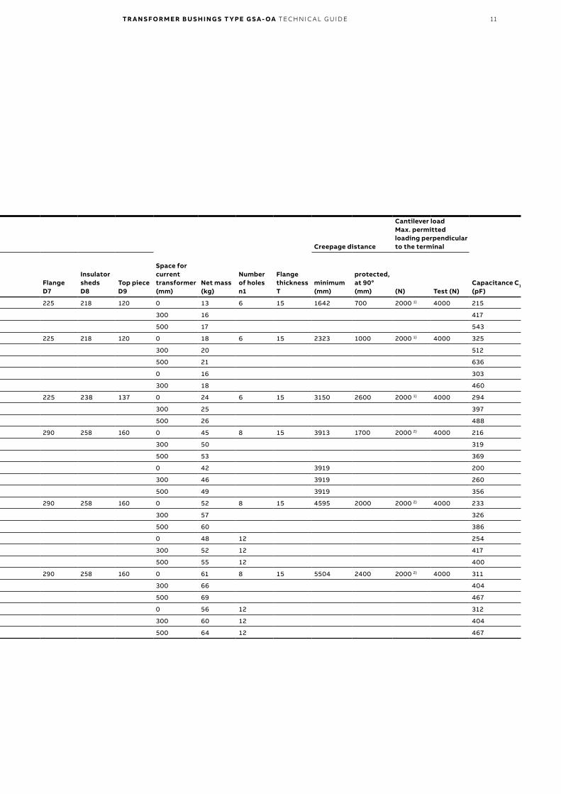
—Table 3. Dimensions.Dimensions are subject to modification without notice.
TypeGSA-OA Cat. No.
Cenelec CLC/TS 50458:2006 denomination
Dimensions in mm
Space for current transformer (mm)
Net mass (kg)
Number of holesn1
Flange thicknessT
Creepage distance
Cantilever loadMax. permitted loading perpendicular to the terminal
Capacitance C1
(pF)TotalL
Oil sideL1
Air sideL2
Draw leadL4
Top partL5
Arcing distanceL7
Flange heightL8
Cond.core(outer)D1
Center holeD2
Min. gasket surface(inner)D5
Hole circleD6
FlangeD7
Insulator shedsD8
Top pieceD9
minimum(mm)
protected, at 90°(mm) (N) Test (N)
52 LF 130 052-BA 52/250/1250-E0 734 145 589 583 56 467 101 96 51 110 185 225 218 120 0 13 6 15 1642 700 2000 1) 4000 215
-BB 52/250/1250-E300 1034 445 300 16 417
-BC 52/250/1250-E500 1234 645 500 17 543
73 LF 130 073-BA - 1029 260 769 763 56 647 101 96 51 110 185 225 218 120 0 18 6 15 2323 1000 2000 1) 4000 325
-BB - 1329 560 300 20 512
-BC - 1529 760 500 21 636
-DA 72.5/325/1250-E0 964 195 200 0 16 303
-DB 72.5/325/1250-E300 1264 495 200 300 18 460
100 LF 130 100-BA - 1334 345 989 983 56 867 101 112 51 136 185 225 238 137 0 24 6 15 3150 2600 2000 1) 4000 294
-BB - 1574 585 300 25 397
-BC - 1774 785 500 26 488
123 LF 130 123-BA - 1444 255 1189 1183 56 1067 101 136 51 150 250 290 258 160 0 45 8 15 3913 1700 2000 2) 4000 216
-BB - 1744 555 300 50 319
-BC - 1944 755 500 53 369
-CA 123/550/1250-E0 1529 340 0 42 3919 200
-CB 123/550/1250-E300 1829 640 300 46 3919 260
-CC 123/550/1250-E500 2029 840 500 49 3919 356
145 LF 130 145-BA - 1731 362 1369 1363 56 1247 101 136 51 150 250 290 258 160 0 52 8 15 4595 2000 2000 2) 4000 233
-BB - 2031 662 300 57 326
-BC - 2231 862 500 60 386
-CA 145/650/1250-E0 1739 370 290 0 48 12 254
-CB 145/650/1250-E300 2039 670 290 300 52 12 417
-CC 145/650/1250-E500 2231 862 290 500 55 12 400
170 LF 130 170-BA - 2019 410 1609 1603 56 1487 101 136 51 150 250 290 258 160 0 61 8 15 5504 2400 2000 2) 4000 311
-BB - 2319 710 300 66 404
-BC - 2519 910 500 69 467
-CA 170/750/1250-E0 2039 430 290 0 56 12 312
-CB 170/750/1250-E300 2339 730 290 300 60 12 404
-CC 170/750/1250-E500 2559 950 290 500 64 12 467
1) Exceeding IEC 60137 Cantilever load Level II.
2) Conforming to IEC 60137 Cantilever load Level II.

12 TR A N S FO R M E R B U S H I N G S T Y PE G S A - OA TEC H N I C A L G U ID E
—Connection details
Terminal stud
Conductor diameter
To flange
Ø 49
M8
13
35L4
Divided ringO-ring
Tightening ring
125
DOuter terminalThe outer terminal needs to be specified in each case. The outer terminal is then used together with either a solid rod, for maximum current capacity, or a flexible lead for greater ease of assembly, when the required current capacity is lower.
The outer terminal is available in a number of standard configurations. Other configurations can be supplied on request.
—Table 4.
Material PlatingStud diameter(mm)
Cat. No.LF 170 079
Mass(kg)
Aluminium - 60 -A (standard) 2.3
- 30 -B (standard) 1.6
Copper - 60 -C (standard) 6.2
- 30 -D (standard) 3.6
Tin 60 -E 6.2
Tin 30 -F 3.6
Silver 60 -G 6.2
Silver 30 -H 3.6
Inner terminalThe inner terminal is made of copper for connection of a draw lead.
—Table 5.
Material and designConductor diameter (mm)
Cat. No.LF 170 080
Mass(kg)
Copper for brazing 5 (pilot hole) -A 1
11 -B 1
13 -C 1
15 -D 1
18 -E 1
30 -F 1
42 -G 1
45 -H 1
Solid rod conductorThe rod is produced from electrolytical copper and divided into two parts for ease of assembly. The parts are joined with a screw joint with undroppable screws. The lower part of the solid rod is designed to enable connection by brazing. The solid rod is available with two alternative dividing points, 20 mm below the bushing flange or 20 mm below the space for current transformer. The solid rod is delivered without paper insulation.
—09 Inner terminal.
—08 Outer terminal.

TR A N S FO R M E R B U S H I N G S T Y PE G S A - OA TEC H N I C A L G U ID E 13
D2D1
D2D1
35476035
Ø 49
Ø 43 Ø 56
Ø 62
Insulate up to here
Dividing point
Insulate up to here
1600 A 2000 A
—Table 6. Ordering particulars for solid rod conductor.
BushingCat. No.
Division at flange Division at current transformer Mass (kg)
Upper partLF 170 081
1600 ALower partLF 170 082
2000 ALower partLF 170 082
Upper partLF 170 081
1600 ALower partLF 170 082
2000 ALower partLF 170 082 1600 A 2000 A
LF 130 052 -BA -ABA -DABA -ABA - - - 13 13.5
-BB -BABA -DABB -ABB -ABB -DBABA -BABA 18 18.5
-BC -CABA -DABC -ABC -ABC -DCABA -CABA 21.5 22
LF 130 073 -BA -BBA -DBBA -BBA - - - 18 18.5
-BB -BBBA -DBBB -BBB -BBB -DBBBA -BBBA 23 23.5
-BC -CBBA -DBBC -BBC -BBC -DCBBA -CBBA 26 26.5
-DA -BBA - -BDA - - - - 18
-DB -BBBA - -BDC - - - - 23
LF 130 100 -BA -HAA -EAA - - - - 23 -
-BB -HAA -EAB - - - - 27 -
-BC -HAA -EAC - - - - 31 -
LF 130 123 -BA -DBA -DADBA - - - - 25 -
-BB -BDBA -DDBB - -DBB -DBDBA - 30 -
-BC -CDBA -DDBC - -DBC -DDBA - 33 -
-CA -DBA -DEBA - - - - 27 -
-CB -DBA -DABC - - - - 32 -
-CC -DBA -DEBC - - - - 36 -
LF 130 145 -BA -EBA -DEBA - - - - 29.5 -
-BB -BEBA -DEBB - -EBB -DBEBA - 33.7 -
-BC -CEBA -DEBC - -EBC -DCEBA - 37.1 -
-CA -EBA -ECA - - - - 30 -
-CB -BEBA -DEBB - - - - 35 -
-CC -CEBA -DEBC - -EBC -DCEBA - 39 -
LF 130 170 -BA -FBA -DAFBA - - - - 34.5 -
-BB -BFBA -DFBB - -FBB -DBFBA - 39.5 -
-BC -CFBA -DFBC - -FBC -DFBA - 42.5 -
-CA -FBA -FCA - - - - 35 -
-CB -BFBA -DFBB - -FBB -DBFBA - 40 -
-CC -CFBA -DFCC - -FBC -DFCB - 44 -
—10 Solid rod conductor.

14 TR A N S FO R M E R B U S H I N G S T Y PE G S A - OA TEC H N I C A L G U ID E
Conductor insulationDraw leads and solid rods must be insulated with vacuum oil-impregnated insulating paper or equivalent, to give sufficient insulation integrity. The paper insulation must be min. 2 mm.
Draw lead: The paper insulation must be brought min. 50 mm inside the bushing centre hole.
Solid rod: The paper must fill the recess and cover the whole solid rod end downwards.
Separate terminal plate with boltsThe separate terminal plate is available for stud with ø 30 mm, and used for connecting the bushing to the line conductor.
—Table 7.
Material Cat. No.
Aluminium LF 170 014-A
Nickel plated copper LF 170 021-A
Arcing hornsArcing horns made of galvanised steel can be mounted on the bushing. The arcing horns are available for stud with ø 30 mm.
The lower rod is fastened onto the flange with one of the fixing screws and the upper rod by means of a bracket on the outer terminal.
The gap distances for standard arcing horns are shown in the table. Other gap distances on request.
—Table 8.
Type GSA-OA Cat. No. K (mm) C (mm) H (mm)
52 LF 170 004-A 230–440 315 112
73 LF 170 004-A 400–620 315 112
100 LF 170 004-G 400–780 315 112
123 LF 170 004-G 620–960 315 114
145 LF 170 005-A 700–1080 380 224
170 LF 170 005-B 820–1290 380 224
C
K
H
—11 Separate terminal plate with bolts.
—12 Arcing horns.
145107
7540 17,5
D=30,5
17,5
M12
<32
13
40 75

TR A N S FO R M E R B U S H I N G S T Y PE G S A - OA TEC H N I C A L G U ID E 15
—Conductor loading
The GSA bushings fulfil the temperature rise test requirements according to IEC and IEEE for the currents in Table 10.
—Table 9.
Type GSA-OA Conductor
Permissible current
IEC (A) IEEE (A)
52-73 kV Solid rod 2000 2000
100-170 kV Solid rod 1600 1600
All types Stranded cable
185 mm2 400 400
740 mm2 1250 1250
—Table 10. Calculated permissible current.
Type GSA-OA Stranded cable (mm2) Permissible current (A)
All types 90 200
150 310
240 480
300 570
400 700
500 820
630 1000
Overloading of bushingsIf the conductor for the bushing is selected with 120 % of the rated current of the transformer, the bushing is considered to be able to withstand the overload conditions stated in IEC 60076-7 without further clarifications or tests, according to IEC 60137.
Short-time currentThe rated thermal short-time current (Ith) is calculated according to IEC 60137.
—Table 11.
ConductorRated current (A)
Area(mm2)
Short-time current (Ith)kA, rms
Dynamic current (Id)kA, peak1 s 2 s
Solid rodØ 49 mm Cu 2000.. 1600 1886 100 96 240
Stranded draw-lead 1250 740 61 43 107

16 TR A N S FO R M E R B U S H I N G S T Y PE G S A - OA TEC H N I C A L G U ID E
—Recommendations for positioning
—14 Recommendations for positioning.
The maximum stresses in the oil at the surface of the conductor insulation must be limited to those values normal for insulated conductors and similar components in the same transformer.
The adjacent recommendations are intended as guide lines when complete calculations are not carried out.
—Table 12.
Type GSAInternal insulation level of transformer (kV)
Distance to earthed parts R (mm)
52 250-95 75
73 350-140 90
100 450-205 140
123 550-230 145
145 650-275 165
170 750-325 190
R min 2
60°
Distance to flat surface e.g. tank or core clamp
Space for current transformers
45°
R min 5
R
Earthed layer

TR A N S FO R M E R B U S H I N G S T Y PE G S A - OA TEC H N I C A L G U ID E 17
—Ordering particulars
When ordering, please state:• Type and catalogue number for bushing.• Catalogue number for inner terminal or
conductor, lower and upper part.• Catalogue number for outer terminal.• Additional accessories or modifications.• Test required, in addition to the normal routine
tests.


—ABB AB, ComponentsSE-771 80 LudvikaSwedenE-mail: [email protected]
www.abb.com/transformercomponents
1ZS
E 2
750
-111
en
, Rev
. 11,
20
19-0
5-1
5
© Copyright 2019 ABB. All rights reserved. Specifications subject to change without notice.