Embed Size (px)
Citation preview
.
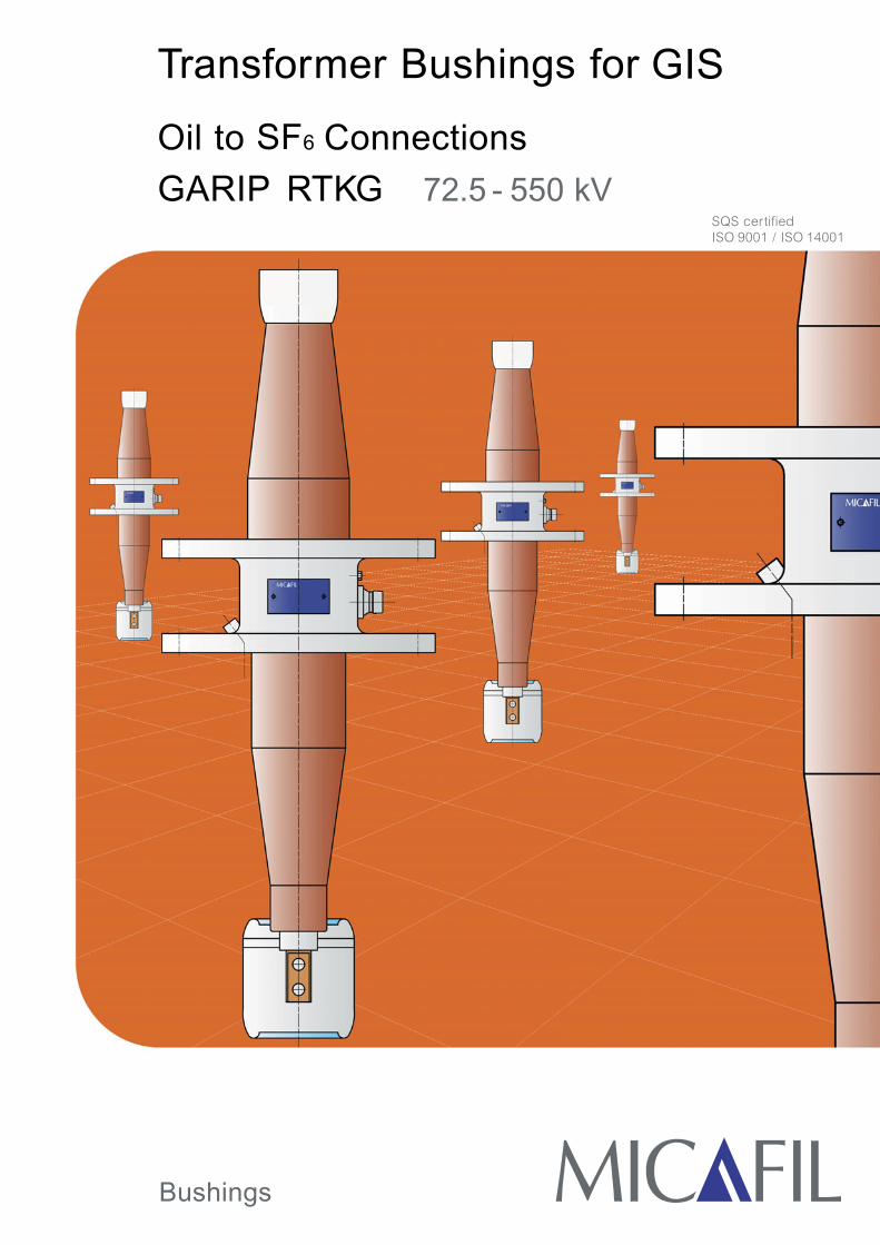
Transformer Bushings for GIS
Oil to SF6 Connections
GARIP RTKG 72.5 - 550 kV
Bushings
SQS certifiedISO 9001 / ISO 14001

In modern metal enclosed switchgear SF6 - gas is usedas an extinguishing and insulating medium, ensuringhighest security standard for operating staff and resi-dents, especially in most confined and dense populatedareas.As a result, today’s space saving design requires excel-lent mechanical and electrical performance of all com-ponents involved.Micafil’s contribution to this world -wide development isit’s new product range of GARIP bushings. These havebeen designed for the direct single phase connectionbetween power transformers and gas insulated switch-gear (GIS) for rated voltages of 72.5 kV up to 550 kV.
Since more than 40 years Micafil AG produces high vol-tage bushings made with Vacuum Resin ImpregnatedPaper Technology (RIP).We are proud of our leading position in this field, makingavailable to our customers profound expertise in thelatest state of the art technology, which is based uponmore than 50000 RIP - bushings successful in operation.
The insulation body of the GARIP condenser bushingseries consists of a robust and solid core, made ofwound crepe paper and inserted aluminium foils for fieldcontrol, carefully vacuum dried and subsequentlyimpregnated with special epoxy resin.
The basic procedure for this new kind of manufacturewas originally developed by Micafil AG in Switzerlandalready in 1958 and continuously improved in the courseof four decades.
Advanced standardisation, highly skilled craftsmanshipand computer-aided engineering guarantee today’smost reliable and advanced insulation system for everyvoltage level.
Main advantages of Micafil’sRIP- technology
• Short delivery times
• Low dielectric losses (tan δ ~ 0.35%)
• Partial discharge free up to double service voltage
• Fully dry, maintenance free
• Oil - free and environmental friendly
• Highest mechanical and thermal properties
• Robust design and vandalism resistant
• Option for any operating position
• Gas and oil tight
• Easy handling
RIP - Technology for SF6 /Oil - Bushings
2

.
Design and Accessories
3
Manufacturing of the main RIP - insulating body includesthe solid and non- removable conductor, resulting in aperfect reliable structure, matching today’s stringentelectrical, thermal and mechanical requirements.
Main features of the SF6 interfaceDimensions and physical properties of GARIP type bu-shings fully comply with all standard aspects accordingto IEC publication 61639.This enables complete compatibility of the interface forboth, producers of transformers and GIS manufacturers.The specifically shaped head both acts as silver-coatedterminal with tapped holes as well as epoxy - coated highvoltage electrode. Therefore additional shields are notnecessary. Only adjacent conductor parts should be welladapted to the bushing terminal.
Intended for the whole range of rated voltages from 72.5to 550 kV, Micafil’s GARIP bushings are specified up to750 kPa working pressure SF6 in the GIS.Our new series of GARIP bushings require minimumfunctional SF6 - gas pressures of 350 kPa (72.5 - 420 kV)and 390 kPa (525 kV) respectively.
Flange designAll flanges are made of corrosion proof aluminiumalloys. Standard equipment encompasses a test tap, fourthreads at the transformer side flange plate either forgrounding or as forcing threads and a de - aeration onthe transformer side.A set of most advanced seals between the main insula-ting RIP - body and the flange systems guarantees per-manent gas and oil tightness during operation.
Test tapAll GARIP bushings include a self - grounded test tapconnecting the outer control layer of the RIP - body forcapacitance and tang measurement on site.
Main features of the transformer interfaceThe scope of new GARIP bushings offers CT spaces of0, 300, and 600 mm as a standard equipment (note:L6min = 100 mm for 170 kV types).Special shields, which are dismountable for betterhandling, are supplied for all bushings with rated voltagegreater than 72.5 kV.
Customised design for every Oil / SF6 application is avai-lable on request.

Technical Data and Dimensions
4
RTKG 362-1300 / 2000RTKG 420-1550 / 2000RTKG 525-1800 / 2000
RTKG 72.5 -350 / 2000RTKG 72.5 -350 / 2500RTKG 123-550 / 2000RTKG 123-550 / 2500RTKG 145-650 / 2000RTKG 170-750 / 2000
RTKG 245-1050 / 2000RTKG 245-1050 / 2500
View A:SF6 side
View A:SF6 side
View B:Oil side
View B:Oil side
RTKG 170-750 / 2500
Flange dimensions for:D13D14
D10D9
D8
D2D5
Test tap
n11 x Øw
n11 x Øwn11 x Øwn11 x Øw
n3 x Øv
n3 x Øvn3 x Øvn3 x Øv
M12 (2 x180°)
M12 (2 x180°)M12 (2 x180°)M12 (2 x180°)M12 (2 x180°)M12 (2 x180°)M12 (2 x180°)
M12 (2 x180°)
Groundedlength
Copper,thickness 30 mm
De-aeration of transformeropposite to test tap
De-aeration of transformeropposite to test tap
Sealing areaRa =1.6 (N7)
Aluminium,silver plated
4 x M1225 deep
Sealing areaRa = 3.2 (N8)
22.5°
15° 30°15° 30°
22.5°11.5° 22.5°11.5°
22.5°11.5°
45°
22.5°45°
22.5°45°
D7
Ø18
d4d5d6
D1
40
s1s2
20L6
2011
5
c6D
4
D3 D4
D3
D4
D3
D4
D3
D12
D11
D12
D11D12
D11
D12
D11
L16
LFL2
L
20
85
80A
B
Dimensiondrawing
Flangedimensions for:
Types 123kV - 245 kV
Types 362kV - 525 kV
Shields removable
prospectus No. D 4352 E

.
5prospectus No. D 4352 E
Technical Data and Dimensions1
23
45
67
89
1011
1213
1415
1617
1819
2021
2223
2425
2627
2829
3031
3233
3435
3637
3839
4041
4243
44
Die
lect
ric d
ata
Dim
ensi
ons
of th
e bu
shin
gT
ype
IEC
601
37IE
EE
C57
.19.
01-2
000
Con
duct
orlo
adin
gM
echa
nica
lde
sign
Adj
acen
tG
ISC
ore,
oil s
ide
Oil
side
term
inal
and
shie
ldF
lang
eF
lang
e,oi
l sid
eF
lang
e,S
F6 s
ide
Cor
e,S
F6 s
ide
Ter
min
alS
F6 s
ide
Rated voltage Ur
Ur / √3
AC test voltage
BIL 1,2/50µs
SIL 250/2500µs
System voltage
to-ground voltage
AC test voltage
BIL 1,2/50µs
SIL 250/2500µs
current
short time
Weight
load, 1 Min.
bending momenton the flange
operating
DG
IS
min
.L
L6L1
6D
1D
7c6
d4d5
d6LF
s1s2
D2
D3
D4
D5
n3 x
Øv
D9
D10
D11
D12
n11
x Ø
wL2
D8
D13
D14
Con
dens
er b
ushi
ng,
oil t
o S
F6,
for
tran
sfor
mer
s
GA
RIP
RT
KG
kVkV
kVkV
kVkV
kVkV
kVkV
AkA
kgkN
kNm
kPa
(abs
)m
mm
mm
mm
mm
mm
mm
mm
mm
mm
mm
mm
mm
mm
mm
mm
mm
mn
x m
mm
mm
mm
mm
mn
x m
mm
m
RT
KG
72.
5-35
0/20
0072
.542
140
325
-69
4416
035
0-
2400
2200
2000
6037 48 58
45
350
250
770
1070
1370
0 300
600
175
475
775
130
90-
52-
-15
020
2016
525
029
022
08
x Ø
1620
026
028
531
58
x Ø
1633
013
099
70
RT
KG
72.
5-35
0/25
0072
.542
140
325
-69
4416
035
0-
3000
2700
2450
7545 60 75
45
350
250
770
1070
1370
0 300
600
175
475
775
130
110
-52
--
150
2020
165
250
290
220
8 x
Ø16
200
260
285
315
8 x
Ø16
330
130
9970
RT
KG
123
-550
/200
012
371
230
550
-92
7318
545
0-
2200
2040
1900
5549 59 69
410
350
300
1180
1480
1780
0 300
600
310
610
910
130
9022
052
107
160
150
2020
165
250
290
220
8 x
Ø16
220
280
305
335
8 x
Ø16
520
130
9970
RT
KG
123
-550
/250
012
371
230
550
-92
7318
545
0-
2850
2650
2500
7165 80 95
410
350
300
1180
1480
1780
0 300
600
310
610
910
130
110
220
5214
018
015
020
2016
525
029
022
08
x Ø
1622
028
030
533
58
x Ø
1652
013
099
70
RT
KG
145
-650
/200
014
584
275
650
-13
888
310
650
-21
0020
0019
0053
51 61 714
1035
030
012
3015
3018
30
0 300
600
360
660
960
130
9022
052
107
160
150
2020
165
250
290
220
8 x
Ø16
220
280
305
335
8 x
Ø16
520
130
9970
RT
KG
170
-750
/200
017
098
325
750
-16
110
236
575
0-
2100
2000
1900
5355 62 72
410
350
300
1390
1590
1890
100
300
600
520
720
1020
130
9022
052
Var
1:10
7/16
0
Var
2:14
0/18
015
020
2016
525
029
022
08
x Ø
1622
028
030
533
58
x Ø
1652
013
099
70
RT
KG
170
-750
/250
017
098
325
750
-16
110
236
575
0-
2600
2500
2400
6575 85 10
04
1035
030
013
9015
9018
90
100
300
600
520
720
1020
152
110
220
5214
018
015
020
2019
029
033
526
012
x Ø
1622
028
030
533
58
x Ø
1652
015
299
70
RT
KG
245
-105
0/20
0024
514
146
010
5085
023
014
642
590
0-
2000
1900
1750
5095 11
012
34
2035
045
017
4020
4023
40
0 300
600
590
890
1190
172
9022
052
Var
1:10
7/16
0
Var
2:14
0/18
018
025
2521
029
033
526
012
x Ø
1645
051
053
556
516
x Ø
1677
017
213
911
0
RT
KG
245
-105
0/25
0024
514
146
010
5085
023
014
642
590
0-
2600
2500
2400
6513
215
417
34
2035
045
017
4020
4023
40
0 300
600
590
890
1190
200
110
220
5214
018
018
025
2524
040
045
037
012
x Ø
1645
051
053
556
516
x Ø
1677
020
013
911
0
RT
KG
362
-130
0/20
0036
220
957
013
0010
5034
522
052
011
7582
521
0020
0019
0053
230
260
290
440
350
540
2110
2410
2710
0 300
600
650
950
1250
282
140
250
5217
629
218
030
3034
062
068
058
016
x Ø
2054
060
064
069
016
x Ø
2010
5028
213
911
0
RT
KG
420
-155
0/20
0042
024
268
015
5011
75-
--
--
2100
2000
1900
5324
027
030
04
4035
054
021
8024
8027
80
0 300
600
720
1020
1320
282
140
250
5217
629
218
030
3034
062
068
058
016
x Ø
2054
060
064
069
016
x Ø
2010
5028
213
911
0
RT
KG
525
-180
0/20
0052
530
379
018
0013
0050
031
875
016
7511
7520
0019
0018
0050
300
335
375
440
390
540
2310
2610
2910
0 300
600
850
1150
1450
342
150
250
5217
629
218
030
3040
062
068
058
016
x Ø
2054
060
064
069
016
x Ø
2010
5034
213
911
0
Rated max. line-
Max. operating
Rated thermal
Cantilever test
Max. operating
SF6: Min.
mm
mm
mm
current, 2s
pressure at 20°C
5L
igh
tnin
g im
pu
lse
with
sta
nd
vo
ltag
e a
cc
ord
ing
to
IE
C 6
01
37
6S
witc
hin
g im
pu
lse
with
sta
nd
vo
ltag
e a
cc
ord
ing
to
IE
C 6
01
37
10
Lig
htn
ing
imp
uls
e w
ithst
an
d v
olta
ge
ac
co
rdin
g t
o I
EE
E C
57
.19
.01
11
Sw
itch
ing
imp
uls
e w
ithst
an
d v
olta
ge
ac
co
rdin
g t
o I
EE
E C
57
.19
.01
exp
lan
atio
ns
of
the
co
lum
ns:
12
Co
nd
uc
tor
loa
din
g a
cc
ord
ing
to
IE
C 6
01
37
& I
EE
E C
57
.19
.00
(ma
x.d
aily
me
an
s:o
il 9
5°C
,S
F6
-ga
s 7
5°C
)
13
Sh
ort
tim
e c
urr
en
t a
fte
r o
pe
ratio
n w
ith r
ate
d c
urr
en
t
20
CT
sp
ac
es
L6
as
sta
nd
ard
,o
the
r le
ng
ths
on
re
qu
est
.N
ote
:L
6m
in=
10
0m
m f
or
17
0kV
typ
es
25
The
co
pp
er
term
ina
l is
flat
with
tw
o h
ole
s Ø
18
mm
26
Bu
shin
gs
Ur
> 7
2.5
kV a
re e
qu
ipp
ed
with
an
oil
en
d s
hie
ld.
The
sh
ield
is e
pox
y c
oat
ed
27
For
be
tte
r h
an
dlin
g t
he
sh
ield
is d
ism
ou
nta
ble
.N
ote
:Fo
r th
e 1
70
kV/2
00
0A
an
d 2
45
kV/2
00
0A
typ
es,
two
dif
fere
nt
shie
ld s
ize
s a
re
ava
ilab
le d
ep
en
din
g o
n t
he
tra
nsf
orm
er
cu
rre
nt

R = RIP InsulationT = Transformer applicationK = Short oil side partG= SF6 -gas application
Nominal current (A)
General Informations
6
Conductor loadingRated current dependent on the bushing lower length(see "Technical Data" page 5 & 6, column 12).Bushings selected with Ir not less than 120% of the ratedcurrent of the transformer are considered to be able towithstand the overload conditions according to IECPublication 60354 (Loading guide).
Recommendations for bushing installationTransformerThe field strength in the oil on the surface of the shieldinsulation must be limited to values normal for insulatedcomponents. As a guideline minimum distances A togrounded transformer parts are given below:
Bushing type
GARIP RTKG 72.5 -350 / 2000
GARIP RTKG 72.5 -350 / 2500
GARIP RTKG 123-550 / 2000
GARIP RTKG 123-550 / 2500
GARIP RTKG 145-650 / 2000
GARIP RTKG 170-750 / 2000
GARIP RTKG 170-750 / 2500
GARIP RTKG 245-1050 / 2000
GARIP RTKG 245-1050 / 2500
GARIP RTKG 362-1300 / 2000
GARIP RTKG 420-1550 / 2000
GARIP RTKG 525-1800 / 2000
Catalogue no.
HLJM 154484
HLJM 154964
HLJM 154504
HLJM 154514
HLJM 154524
HLJM 154534
HLJM 154544
HLJM 154554
HLJM 154564
HLJM 154574
HLJM 154584
HLJM 154594
TypeRTKG
123
145
170
245
362
420
525
A(mm)
130145
170200
210230
300
400
450500
550600
A
AC testvoltage (kV)
185230
275310
325365
460
570
630680
750790
Type designationThe type designation is included in an overall system. Anexample of nomenclature used to designate our GARIPbushings:
GARIP RTKG 245-1050 / 2000
Testing of the bushingEach bushing undergoes routine testing before leavingthe factory, either according to IEC 60137 or IEEEC57.19.00.
The standard tests include:
• Tan δ, capacitance and partial discharge measure-ment
• Power frequency test• Lightning impulse test (if applicable)• Leakage test
Ordering particularsWhen ordering please state:
• Type and catalogue no. see the table below• CT space L6, see "Technical Data" page 5 & 6, column
20• For 170 kV / 2000 A respective 245 kV / 2000 A only:
choose the size of oil side shield depending on thetransformer current; see "Technical Data" page 5 & 6,columns 26 &27
Lightning impulsevoltage (kV)
Rated voltage (kV)
Bushing series
GISObserve the minimum enclosurediameter DGIS as well as the minimumoperating SF6 - gas pressure (see"Technical Data" page 5 & 6, columns17 & 18). Adjacent conductor parts shouldbe well adapted to the bushing terminal.
GeneralBecause the bushing is completely dry it can beoperated vertically or horizontally or in any position.

.
Continuity over the last 75 Years
Micafil AGBadenerstrasse 780CH- 8048 ZurichSwitzerland
Phone +41 (0)58 586 03 33Fax +41 (0)58 586 04 44E-mail [email protected] www.micafil.chG
AR
IP2
00
3e
n/S
OP
rosp
ec
tus
no
. D4
35
2E
Pri
nte
d in
Sw
itze
rla
nd
Alte
rna
tion
s re
serv
ed
-
P
ho
tog
rap
hy
& la
you
t by
RG
B P
ho
to G
mb
H, Z
uri
ch