Embed Size (px)
Citation preview

Page | 1
Transformer: 4 Legged Multi
Terrain Robot
Presented By:
Ayush Poddar (13186)
Harshit Lathi (13295)
Anirban Manna (13113)
Yugesh Kumar (13816)
Page | 2
Acknowledgement
This project has been done under Robotics Club, IIT Kanpur by 4 1st Year
undergraduate students namely Ayush Poddar, Harshit Lathi, Anirban Manna
and Yugesh Kumar. This project would not have been possible without the help
and mentorship of some senior members of Robotics Club namely Shubham
Patel, Rishi Gupta, Akshay Masare, Deep Goel, Hardik Soni and Pranav Vyas.

Page | 3
Abstract
All-terrain vehicles are generally based on either rolling or walking mechanism.
The idea behind this project is to build an All-Terrain Vehicle which combines
rolling and walking mechanism.
The 4 Legged multi terrain robot consists of four leg-wheel hybrid units which
can transform between the two mentioned mechanisms. Servos and motors are
used to actuate these units. Each unit has 4 degrees of freedom. The robot is
programmed to transform according to the terrain automatically. All
programming has been done on Arduino Mega
Page | 4
Content
1. INTRODUCTION 5
2. MECHANICAL 6
2.1. DESIGN 6
2.2. SERVOS 7
2.3. SERVO BRACKETS 8
2.4. CHASIS 10
3. ELECTRONICS 11
3.1. MOTOR DRIVER 11
3.2. ARDUINO 12
3.3. LM7806 12
3.4. BLUETOOTH MODULE 13
4. PROGRAMMING & COMMUNICATION 14
5. CONCLUSION 15
5.1. FUTURE SCOPE 15
5.2. VIDEO LINK 15
5.3. REFERENCE 15

Page | 5
Introduction Transformer: 4 LEGGED MULTI TERRAIN ROBOT is a project completed in Summer Camp'14 under Robotics Club, IIT Kanpur. This project justifies its name "Transformer" as the robot can change its orientation according to its environment such as traversing through narrow passage, crawling on a rough surface, climbing a slope and changing its height. The robot has 4 legs and each leg consists of 4 servos and 1 DC motor. Each leg has 4 degrees of freedom making it capable of transforming so as to perform the afore-mentioned tasks. The robot is controlled via Arduino Mega and it is driven using a Bluetooth module.

Page | 6
Mechanical
Design:
Designing is the most important aspect of a robot. Hence, a 3-D design of
the robot was initially worked out on Autodesk Inventor. The robot has 4 leg-
wheel hybrid each consisting of 4 servos, 1 motor and 1 wheel resulting in 4
degrees of freedom. The following images shows the final design of the arm and
robot.
Fig: Design of the leg wheel hybrid
Fig: Design of the robot

Page | 7
Servo:
A servomotor is a rotary actuator that allows for precise control of
angular position, velocity and acceleration. It consists of a suitable motor
coupled to a sensor for position feedback. It also requires a relatively
sophisticated controller, often a dedicated module designed specifically for use
with servomotors.
Servomotors are not a specific class of motor although the term servomotor is
often used to refer to a motor suitable for use in a closed-loop control system.
Servomotors are used in applications such as robotics, CNC machinery
or automated manufacturing.
The following diagram is of the servo that is used in the project.

Page | 8
Specifications:
Dimensions: 40.8 × 20.1 × 38 mm
Weight: 56 g
Operating Speed: 0.18sec/60degree (4.8V)0.16sec/60degree (6V)
Stall Torque: 14kg.cm/194.8 oz.in (4.8V) 15.5kg.cm/215.6oz.in (6V)
Operating Voltage: 4.8V~6V
Control System: Analog
Direction: CCW
Operating Angle: 180degree
Required Pulse: 500us-2500us
Gear Type: Metal
Motor Type: Carbon
Connector Wire Length: 30 cm
Servo Brackets:
Aluminum servo brackets were used to mount the servos. The various
types of servo brackets that were used are shown below.
1. C Bracket: It is connected to the end of the servo motor. It is compatible
with all standard size servo motors.
Material: Aluminum
Thickness: 1.5 mm
Weight: 12 g

Page | 9
2. Universal Servo Bracket: It is used for holding standard sized servo
motor. It is used with other brackets to create interesting links. It is one of
the most popular servo bracket in use. It is compatible with all standard
size servo motors.
Material: Aluminum
Thickness: 1.5 mm
Weight: 13 g
3. Universal Inline Dual Servo Bracket: Used for holding two servo motors straight line. It can be used for creating pretty interesting link designs.
Material: Aluminum
Thickness: 1.5 mm
Weight: 32 g

Page | 10
Chassis:
The chassis is made of plywood coated with glass fiber. Glass fiber was used to
make the robot as light and strong as possible.
Dimensions: 30cm x 25cm x 0.2cm
Type of fiber glass: Polyester resin (Not reinforced)
Specific gravity: 1.28
Tensile strength MPa (ksi): 55 (7.98)
Compressive strength MPa (ksi): 140 (20.3)

Page | 11
Electronics
The following electrical components were used in the robot:
Motor Driver:
A motor driver is a device or group of devices that serves to govern in
some predetermined manner the performance of an electric motor. A motor
controller might include a manual or automatic means for starting and stopping
the motor, selecting forward or reverse rotation, selecting and regulating the
speed, regulating or limiting the torque, and protecting against overloads and
faults. 8V-28V, 5Amp Dual DC Motor Driver with Current Sense can drive 2
DC motors with current up to 5Amps. It can work between 8 to 28V DC and
gives current sense output for each motor. Motor driver has built-in protection
from over temperature, over current, short circuit. It also gives out fault
indications for the over/under voltage, over temperature, over current / short
circuit. Motor driver has 6-pin removable XY connector on the power side and
separate 6 pin 2510 replicate connectors for logic connections of each motor
driver section. Motor driver can drive 2 motors with peak load of 5Amps. If
temperature of the motor driver goes beyond 1500C motor driver will restrict
maximum output current to 4Amps. When temperature of the motor driver
reaches above 1700C motor driver will shut down. You need to restart motor
driver to resume operation. If output current exceeds 6.5Amps the motor driver
will turn off the motor driver output to protect it against short circuit.
Page | 12
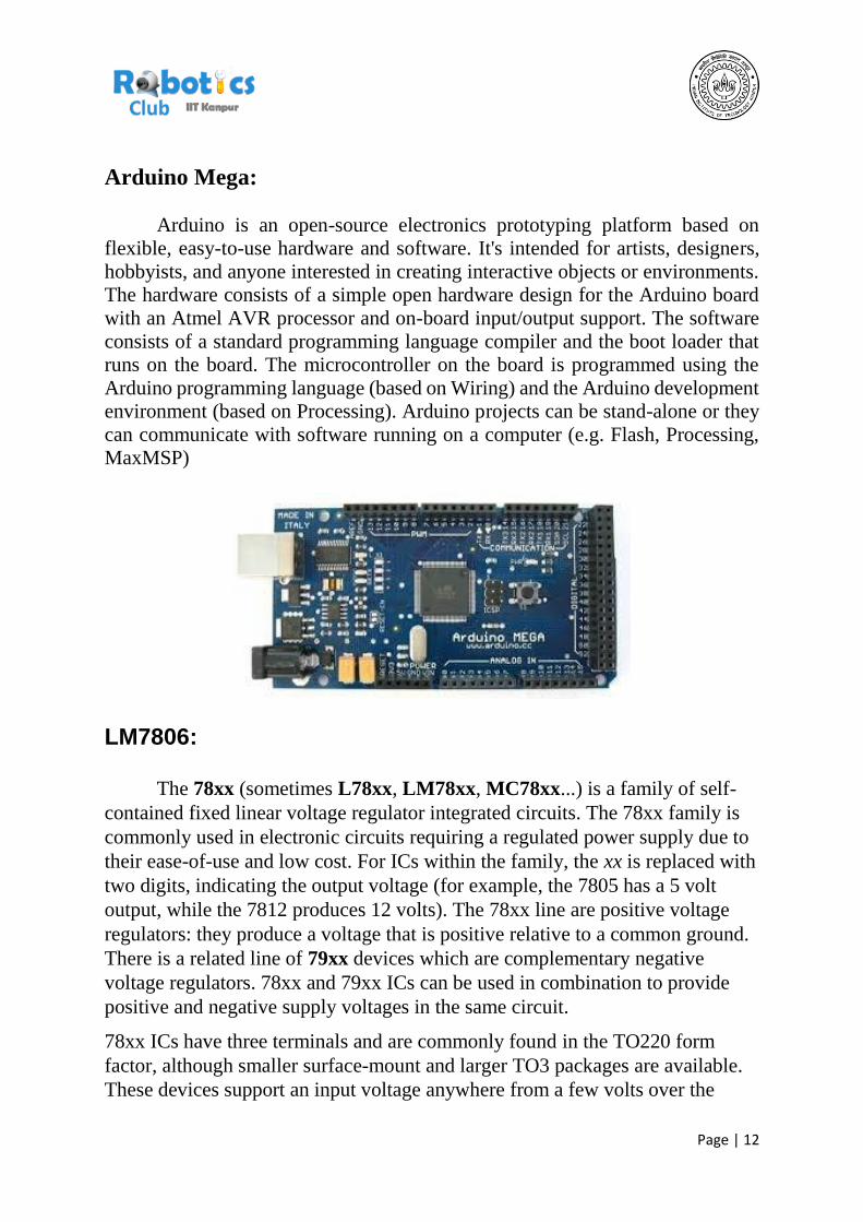
Arduino Mega:
Arduino is an open-source electronics prototyping platform based on
flexible, easy-to-use hardware and software. It's intended for artists, designers,
hobbyists, and anyone interested in creating interactive objects or environments.
The hardware consists of a simple open hardware design for the Arduino board
with an Atmel AVR processor and on-board input/output support. The software
consists of a standard programming language compiler and the boot loader that
runs on the board. The microcontroller on the board is programmed using the
Arduino programming language (based on Wiring) and the Arduino development
environment (based on Processing). Arduino projects can be stand-alone or they
can communicate with software running on a computer (e.g. Flash, Processing,
MaxMSP)
LM7806: The 78xx (sometimes L78xx, LM78xx, MC78xx...) is a family of self-
contained fixed linear voltage regulator integrated circuits. The 78xx family is
commonly used in electronic circuits requiring a regulated power supply due to
their ease-of-use and low cost. For ICs within the family, the xx is replaced with
two digits, indicating the output voltage (for example, the 7805 has a 5 volt
output, while the 7812 produces 12 volts). The 78xx line are positive voltage
regulators: they produce a voltage that is positive relative to a common ground.
There is a related line of 79xx devices which are complementary negative
voltage regulators. 78xx and 79xx ICs can be used in combination to provide
positive and negative supply voltages in the same circuit. 78xx ICs have three terminals and are commonly found in the TO220 form
factor, although smaller surface-mount and larger TO3 packages are available.
These devices support an input voltage anywhere from a few volts over the

Page | 13
intended output voltage, up to a maximum of 35 to 40 volts depending on the
make, and typically provide 1 or 1.5 amperes of current (though smaller or
larger packages may have a lower or higher current rating). In this project we
have used 7806 to convert 7.4 volts to 6 volts. Four 7806 has been used in this
project and each 7806 provide power to 4 servos.
Bluetooth Module: Bluetooth is a wireless technology standard for exchanging data
over short distances (using short-wavelength UHF radio waves in the
ISM band from 2.4 to 2.485 GHz from fixed and mobile devices, and
building personal area networks (PANs). Invented by telecom vendor
Ericsson in 1994, it was originally conceived as a wireless alternative to
RS-232 data cables. It can connect several devices, overcoming
problems of synchronization. Bluetooth is managed by the Bluetooth Special Interest Group (SIG), which has more than 20,000 member companies in the areas of telecommunication, computing, networking, and consumer electronics. Bluetooth was standardized as IEEE 802.15.1, but the standard is no longer maintained. The SIG oversees the development of the specification, manages the qualification program, and protects the trademarks. To be marketed as a Bluetooth device, it must be qualified to standards defined by the SIG. A network of patents is required to implement the technology, which is licensed only for that qualifying device.

Page | 14
Programming & Communication
Arduino Mega was programmed using the software Arduino 1.0.5. The
programming language that was mostly C++ while few inbuilt syntax of the
software has been used. The communication between computer and Arduino
was done at a Baud Rate of 9600 Bd. Putty was used to establish the serial
communication.
The code can be found in the following link:
https://drive.google.com/folderview?id=0B86ufPFYJVAUQVVjX25UQUdhW
Wc&usp=sharing

Page | 15
Conclusion
Future Scope:
The next phase of the project will be to make this robot fully autonomous by installing sensors so that it can detect terrain and transform accordingly.
Video Link:
https://www.youtube.com/watch?v=6tD3dsDzbeg
References:
1. https://www.youtube.com/watch?v=6tD3dsDzbeg
2. http://www.electrical4u.com/servo-motor-servo-mechanism-theory-and-
working-principle/
3. https://www.arduino.cc/


![Steering of an Underactuated Legged Robot through Terrain ...ronf/PAPERS/casarez...[5], adjusting foot placement by iSprawl [6], and differ-ential drive of motors driving multiple](https://img.dokumen.tips/doc/110x75/5f82edcfa3c93513b0643db2/steering-of-an-underactuated-legged-robot-through-terrain-ronfpaperscasarez.jpg)