Embed Size (px)
Citation preview


Transformations and OSGM02 user guide preface v2.1 9/2002 © crown copyright
Page 1
Preface This grid transformation software and user guide has been commissioned by a consortium comprising Ordnance Survey Great Britain, Ordnance Survey Ireland (OSi), and Ordnance Survey of Northern Ireland (OSNI). These organisations are responsible for the official, definitive topographic mapping of their respective countries.
This user guide contains all the information you need to make effective use of the Ordnance Survey Grid Transformations in the UK and Ireland, and the Ordnance Survey Geoid model (OSGM02™). Within Great Britain coordinates are transformed using the Ordnance Survey National Grid Transformation (OSTN02™). Within the Republic of Ireland and Northern Ireland, the OSi/OSNI Polynomial Transformation is used. OSGM02 is used to transform heights throughout the UK and Ireland.
Users wishing to incorporate the pre-prepared .dll should refer to the Grid InQuest 6.0 user guide.
The intention of this guide is to help you understand the information contained in the data, as well as providing detailed technical information and the data format specification; however it is assumed that users have some appreciation of coordinate systems and datums. This user guide has been checked and validated before issue and every endeavour made to ensure that the contents are accurate. If you find an error, omission, or otherwise wish to make a suggestion as to how this user guide can be improved, please contact us at the address shown under Contact details.
Contact details For users in Great Britain and the Isle of Man:
The Geospatial Development Team will be pleased to deal with your enquiries:
Email: [email protected]
or write to:
The Geospatial Development Team Ordnance Survey Romsey Road SOUTHAMPTON United Kingdom SO16 4GU
Web site: www.gps.gov.uk

Transformations and OSGM02 user guide preface v2.1 9/2002 © crown copyright
Page 2
For users in Northern Ireland:
Ordnance Survey of Northern Ireland Colby House Stranmillis Court Belfast Northern Ireland BT9 5BJ
Web site: www.osni.gov.uk
For users in the Republic of Ireland:
Ordnance Survey Ireland Phoenix Park Dublin 8 Ireland
Web site: www.osi.ie
Liability OSTN02™ and OSGM02™ are provided free of charge by Ordnance Survey® and (where relevant) Ordnance Survey Northern Ireland™ and Ordnance Survey Ireland™ on an as is and as and when available basis to users. A user of either OSTN02, the OSi/OSNI™ polynomial transformation, or OSGM02 does so at their own risk. Downloading of any dynamic link library (.dll) files from this site is made without any representation or warranty or condition, whether expressed or implied; in particular it is without representation, warranty or condition that OSTN02, the OSi/OSNI polynomial transformation, and OSGM02 are error free, free from viruses or other harmful components or as to the accuracy, content, completeness, legality, reliability, quality or suitability of them other than those implied by statute.
Ordnance Survey and (where relevant) Ordnance Survey Northern Ireland and Ordnance Survey Ireland shall not be liable to a user or any third party for any losses, costs, claims or indirect, special, incidental, punitive, or consequential damages arising out of access, downloading or use of OSTN02, the OSi/OSNI polynomial transformation, or OSGM02.

Transformations and OSGM02 user guide preface v2.1 9/2002 © crown copyright
Page 3
Data copyright Copyright and any database right or other intellectual property right in the OSTN02 data available from this site, however it is made available, belongs to Ordnance Survey (and is therefore Crown copyright). Copyright and any database right or other intellectual property right in OSGM02 data available from this site, however it is made available, belongs jointly to Ordnance Survey, Ordnance Survey Northern Ireland (and is protected by Crown copyright) and Ordnance Survey Ireland.
Ordnance Survey and (where relevant) Ordnance Survey Northern Ireland and Ordnance Survey Ireland permit users to copy or incorporate copyrighted material from both OSTN02, the OSi/OSNI polynomial transformation, or OSGM02 either onto their own PCs or into their software. However, this is dependant on the appropriate copyright notice being displayed in the software. The appropriate notices are '© Ordnance Survey Ireland, 2002' or '© Crown copyright 2002. All rights reserved.' as applicable. The appropriate mapping agency logo must also appear next to the copyright notice. Details of mapping agency logos are found in the style guides available on the web site.
User guide copyright This user guide is © Crown copyright 2002. All rights reserved. It accompanies OSTN02 and OSGM02 data to allow you to make effective use of the data. Any part of this guide may be copied for business use. Business use is defined as actions related to business decision making or as part of day-to-day operations associated with the running of the business. No part of the guide may be copied or incorporated in products, services or publications a user generates for onward sale or as free promotional support material, without the prior written permission of Ordnance Survey.
Trademarks Ordnance Survey, the OS Symbol and OSGB36 are registered trademarks and OSTN02 is a trademark of Ordnance Survey, the national mapping agency of Great Britain. OSGM02 is a trademark of Ordnance Survey, Ordnance Survey Northern Ireland and Ordnance Survey Ireland. Ordnance Survey Northern Ireland, OSNI and the OSNI Symbol are trademarks of Ordnance Survey Northern Ireland. The OSi Symbol is a registered trademark of Ordnance Survey Ireland. Ordnance Survey Ireland and OSi are trademarks of Ordnance Survey Ireland.

Transformations and OSGM02 user guide contents v2.1 9/2002 © crown copyright
Page 4
Contents Chapter 1 Introduction ..........................................................................................................................................................................................6
Coordinate transformations and the Geoid model ...............................................................................................................................6 OSTN02 ................................................................................................................................................................................................7 OSi/OSNI polynomial transformation ....................................................................................................................................................7 Ordnance Survey Geoid model: OSGM02 ...........................................................................................................................................8 ETRS89 explained ................................................................................................................................................................................9 Benefits.................................................................................................................................................................................................9 Applications........................................................................................................................................................................................10
Chapter 2 Data overview.....................................................................................................................................................................................11 Basic principles..................................................................................................................................................................................11 Data structure.....................................................................................................................................................................................12
OSTN02/OSGM02 within Great Britain – format and layout of the data........................................................................................12 OSGM02 within Northern Ireland – format and layout of the data ................................................................................................13 OSGM02 within the Republic of Ireland – format and layout of the data ......................................................................................15
Chapter 3 Ordnance Survey transformations and OSGM02 explained ..............................................................................................................18 OSTN02 ..............................................................................................................................................................................................18
Transforming ETRS89 coordinates to OSGB36 National Grid: overview ......................................................................................18 Calculating which data record to use ...........................................................................................................................................18 Procedure for transforming ETRS89 to OSGB36 coordinates ......................................................................................................19 Inverse transformation (OSGB36 to ETRS89) ...............................................................................................................................22
The OSi/OSNI polynomial transformation ...........................................................................................................................................23 Table of coefficients for OSi/OSNI polynomial transformation ......................................................................................................24
The Ordnance Survey Geoid model: OSGM02 ..................................................................................................................................25 Chapter 4 Quality statement................................................................................................................................................................................27
Coverage............................................................................................................................................................................................27 Accuracy of Ordnance Survey transformations..................................................................................................................................27 Accuracy of OSGM02.........................................................................................................................................................................28
Transformations and OSGM02 user guide contents v2.1 9/2002 © crown copyright
Page 5
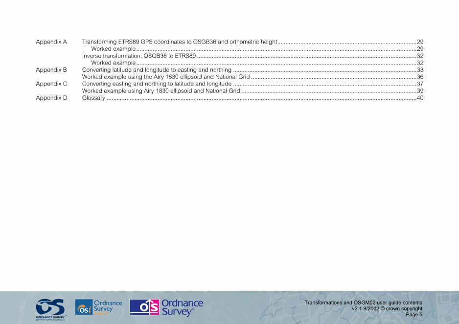
Appendix A Transforming ETRS89 GPS coordinates to OSGB36 and orthometric height.....................................................................................29 Worked example...........................................................................................................................................................................29
Inverse transformation: OSGB36 to ETRS89 ......................................................................................................................................32 Worked example...........................................................................................................................................................................32
Appendix B Converting latitude and longitude to easting and northing ................................................................................................................33 Worked example using the Airy 1830 ellipsoid and National Grid .....................................................................................................36
Appendix C Converting easting and northing to latitude and longitude ................................................................................................................37 Worked example using Airy 1830 ellipsoid and National Grid ...........................................................................................................39
Appendix D Glossary .............................................................................................................................................................................................40

Transformations and OSGM02 user guide chapter 1 v2.1 9/2002 © crown copyright
Page 6
Chapter 1 Introduction
Coordinate transformations and the Geoid model All Ordnance Survey mapping relates to a coordinate reference system. In Great Britain Ordnance Survey coordinates relate to OSGB36® (the National Grid); within Northern Ireland and the Republic of Ireland the coordinate reference system is the Irish Grid. These reference systems are traditionally realised on the earth's surface by monumented triangulation stations. The users of mapping products, in both the public and private sectors, have invested in geographical information systems (GIS) and asset management systems based on these grid systems, which have been accepted as de facto national standards.
The National Grid and the Irish Grid are capable of supporting surveying and mapping in UK and Ireland to meet all the requirements of users both now and in the future; however, an increasing number of spatial datasets are available in GPS (Global Positioning System) coordinate systems. When two or more coordinate datasets are to be integrated, it is essential that each relates to the same coordinate reference system, irrespective of accuracy issues.
In order to relate GPS-derived positions to Ordnance Survey's mapping, GPS coordinates need to be converted to Irish Grid or to National Grid, which requires a specialised datum transformation. For this reason the Ordnance Survey of Northern Ireland and Ordnance Survey Ireland have developed a polynomial transformation, which is the standard datum transformation for use throughout Ireland. The Ordnance Survey of Great Britain has developed OSTN02, the standard datum transformation for Great Britain.
Ordnance Survey mapping also includes height information that relates to a regional vertical datum. Height information in Great Britain refers to Ordnance Datum Newlyn (ODN), which is established from mean sea level. Although ODN is the national height datum used across mainland Great Britain there are a number of additional datums that are used on the surrounding islands, for example: Lerwick on the Shetland Islands; Stornoway on the Outer Hebrides; St Kilda; Douglas02 on the Isle of Man and St Marys on the Scilly Isles. The Ordnance Survey of Northern Ireland relates heights within Northern Ireland to Belfast Lough datum, and Ordnance Survey Ireland relates heights within the Republic of Ireland to the Malin Head datum.

Transformations and OSGM02 user guide chapter 1 v2.1 9/2002 © crown copyright
Page 7
Orthometric heights in these systems have in the past been realised via a network of Ordnance Survey bench marks (BMs). These traditional levelling networks cover the whole of Great Britain, Northern Ireland and the Republic of Ireland. However, heights from precise GPS surveying are relative to a reference ellipsoid that approximates to the shape of the earth but does not coincide with mean sea level. To enable GPS to be used to determine orthometric heights, the Ordnance Surveys have jointly developed a model to establish the precise relationship between the two vertical reference surfaces. The resulting Ordnance Survey Geoid model (OSGM02) incorporates all the above vertical datums.
OSTN02 The Ordnance Survey of Great Britain has developed the horizontal transformation OSTN02. This transformation consists of a 700 km by 1 250 km grid of translation vectors at 1 km resolution. This provides a fit between the GPS coordinate system ETRS89 (European Terrestrial Reference System 1989) and the OSGB36 National Grid. OSTN02 is in agreement with major triangulation stations at the level of 0.1 m root mean square error (RMSE).
OSTN02 has been developed from the national primary, secondary and tertiary triangulation station network. It contains over 3 200 points directly observed by GPS and more than 1 000 from the original retriangulation observations adjusted on the ETRS89 datum.
Within Great Britain OSTN02 (the Ordnance Survey National Grid Transformation), in conjunction with the ETRS89 positions of the active GPS network stations, is now the official definition of OSGB36 National Grid coordinate system. This means that using OSTN02 with the National GPS Network, surveyors using GPS have no need to occupy triangulation stations in order to relate GPS coordinates to National Grid coordinates.
OSi/OSNI polynomial transformation Ordnance Survey Ireland and Ordnance Survey of Northern Ireland recommend the OSi/OSNI polynomial transformation for all horizontal transformations in the Republic of Ireland and Northern Ireland. This transformation has been developed in association with the Institute of Engineering Surveying and Space Geodesy, University of Nottingham.
Transformations and OSGM02 user guide chapter 1 v2.1 9/2002 © crown copyright
Page 8
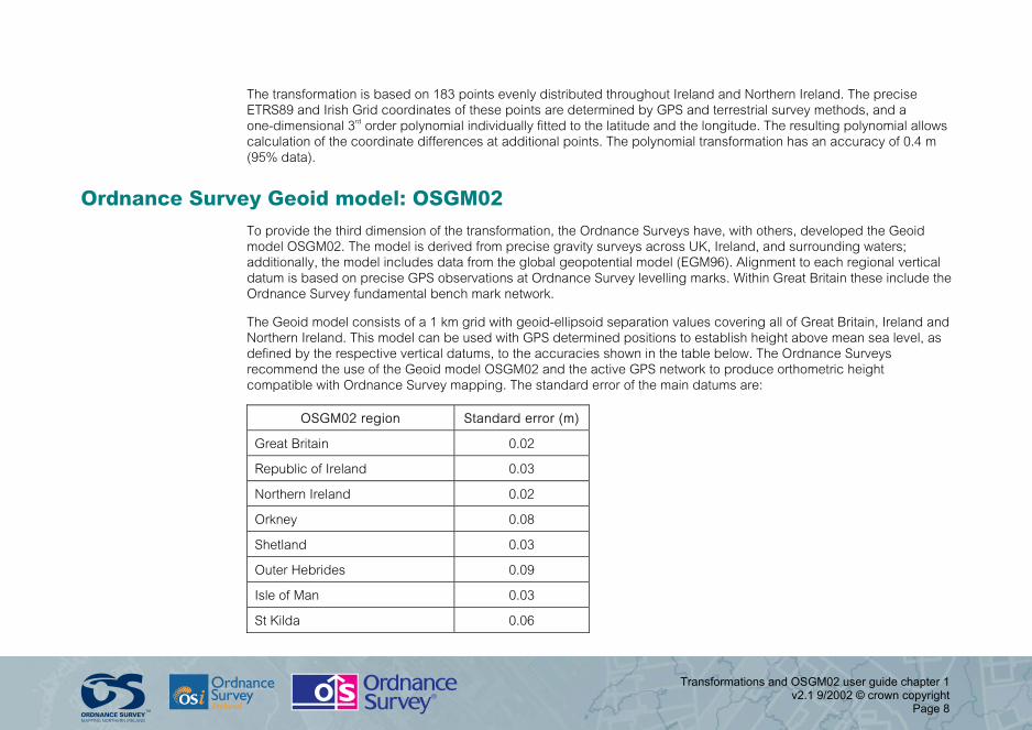
The transformation is based on 183 points evenly distributed throughout Ireland and Northern Ireland. The precise ETRS89 and Irish Grid coordinates of these points are determined by GPS and terrestrial survey methods, and a one-dimensional 3rd order polynomial individually fitted to the latitude and the longitude. The resulting polynomial allows calculation of the coordinate differences at additional points. The polynomial transformation has an accuracy of 0.4 m (95% data).
Ordnance Survey Geoid model: OSGM02 To provide the third dimension of the transformation, the Ordnance Surveys have, with others, developed the Geoid model OSGM02. The model is derived from precise gravity surveys across UK, Ireland, and surrounding waters; additionally, the model includes data from the global geopotential model (EGM96). Alignment to each regional vertical datum is based on precise GPS observations at Ordnance Survey levelling marks. Within Great Britain these include the Ordnance Survey fundamental bench mark network.
The Geoid model consists of a 1 km grid with geoid-ellipsoid separation values covering all of Great Britain, Ireland and Northern Ireland. This model can be used with GPS determined positions to establish height above mean sea level, as defined by the respective vertical datums, to the accuracies shown in the table below. The Ordnance Surveys recommend the use of the Geoid model OSGM02 and the active GPS network to produce orthometric height compatible with Ordnance Survey mapping. The standard error of the main datums are:
OSGM02 region Standard error (m)
Great Britain 0.02
Republic of Ireland 0.03
Northern Ireland 0.02
Orkney 0.08
Shetland 0.03
Outer Hebrides 0.09
Isle of Man 0.03
St Kilda 0.06

Transformations and OSGM02 user guide chapter 1 v2.1 9/2002 © crown copyright
Page 9
Ordnance Survey Great Britain intend that OSGM02 is the official definition of the relationship between GPS ellipsoid heights and orthometric height in Great Britain. In the way that GPS and the transformation model OSTN02 define the horizontal coordinate system, precise GPS surveying using the Ordnance Survey Great Britain active GPS Network in conjunction with the Geoid model will become the standard method of determining orthometric height.
ETRS89 explained The Ordnance Survey transformations and OSGM02 link the Ordnance Survey coordinate reference systems and vertical datums to the GPS-compatible coordinate system ETRS89. In Europe, ETRS89 is a precise version of the better known WGS84 reference system optimised for use in Europe; however, for most purposes it can be considered equivalent to WGS84.
Specifically, the motion of the European continental plate is not apparent in ETRS89, which allows a fixed relationship to be established between this system and Ordnance Survey mapping coordinate systems.
Additional precise versions of WGS84 are currently in use, notably ITRS; these are not equivalent to ETRS89. The difference between ITRS and ETRS89 is in the order of 0.25 m (in 1999), and growing by 0.025 m per year in UK and Ireland. This effect is only relevant in international scientific applications. For all navigation, mapping, GIS, and engineering applications within the tectonically stable parts of Europe (including UK and Ireland), the term ETRS89 should be taken as synonymous with WGS84.
Benefits Together, the Ordnance Survey transformations and OSGM02 provide the complete solution to relating GPS (WGS84) datasets to Ordnance Survey mapping in three dimensions. Used with the active GPS network, they allow GPS surveying within the National Grid or the Irish Grid, and to the appropriate vertical datum, without the need to visit any Ordnance Survey traditional control points. These new standards bring the benefits of simplicity and uniformity.

Transformations and OSGM02 user guide chapter 1 v2.1 9/2002 © crown copyright
Page 10
Applications The Ordnance Survey transformations and OSGM02 are of interest to:
• GPS surveyors who need to relate their survey to the National Grid or the Irish Grid and/or OD orthometric heights – used with the active GPS Network, these products remove the need to visit traditional Ordnance Survey horizontal and vertical control points; and
• GIS, GPS, CAD and navigation system developers who need to integrate GPS (WGS84) datasets with Ordnance Survey mapping – these products provide the complete solution to these users at all Ordnance Survey mapping scales.
Transformations and OSGM02 user guide chapter 2 v2.1 9/2002 © crown copyright
Page 11
Chapter 2 Data overview
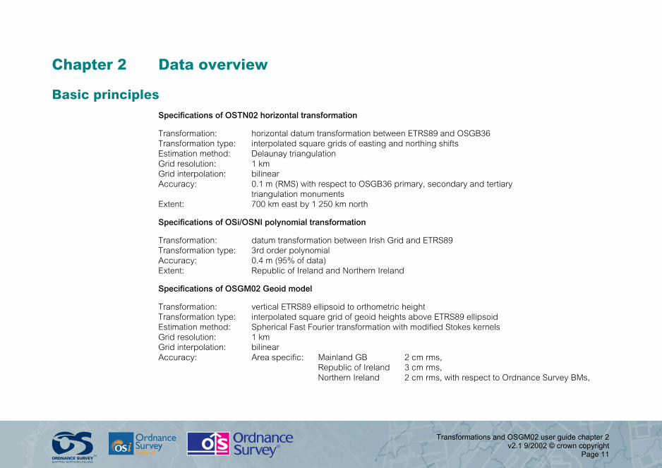
Basic principles Specifications of OSTN02 horizontal transformation
Transformation: horizontal datum transformation between ETRS89 and OSGB36 Transformation type: interpolated square grids of easting and northing shifts Estimation method: Delaunay triangulation Grid resolution: 1 km Grid interpolation: bilinear Accuracy: 0.1 m (RMS) with respect to OSGB36 primary, secondary and tertiary triangulation monuments Extent: 700 km east by 1 250 km north
Specifications of OSi/OSNI polynomial transformation
Transformation: datum transformation between Irish Grid and ETRS89 Transformation type: 3rd order polynomial Accuracy: 0.4 m (95% of data) Extent: Republic of Ireland and Northern Ireland
Specifications of OSGM02 Geoid model
Transformation: vertical ETRS89 ellipsoid to orthometric height Transformation type: interpolated square grid of geoid heights above ETRS89 ellipsoid Estimation method: Spherical Fast Fourier transformation with modified Stokes kernels Grid resolution: 1 km Grid interpolation: bilinear Accuracy: Area specific: Mainland GB 2 cm rms, Republic of Ireland 3 cm rms, Northern Ireland 2 cm rms, with respect to Ordnance Survey BMs,

Transformations and OSGM02 user guide chapter 2 v2.1 9/2002 © crown copyright
Page 12
Data structure
OSTN02/OSGM02 within Great Britain – format and layout of the data
Within Great Britain OSTN02 and OSGM02 are released as a combined data file using the same 1 km grid. This grid covers an area 700 km east–west and 1 250 km north–south, the origin being the origin of the projected ETRS89 coordinates (see appendix B). However, the area to which the models are valid has been cookie cut to a 10 km polygon beyond the coastline. This means that any position more than 10 km offshore will have fields 4, 5, 6 and 7 (see below) all set to zero.
It is strongly recommended that the transformation software be written to return an outside transformation boundary type error when a point outside this area is encountered.
Each record occupies a separate line with the south-west corner of the grid being the first record in the file. The format of each record is indicated by the following table:
Record no1 ETRS89 easting2 (m)
ETRS89 northing3 (m)
OSTN02 east shift4(m)
OSTN02 north shift5(m)
OSGM02
Geoid Ht6 (m)
Geoid datum flag7
1 0 0
2 1 000 0
3 2 000 0
and so on and so on and so on
701 700 000 0
702 0 1 000
703 1 000 1 000
704 2 000 1 000
and so on and so on and so on
876 948 697 000 1 250 000
876 949 698 000 1 250 000
876 950 699 000 1 250 000
876 951 700 000 1 250 000

Transformations and OSGM02 user guide chapter 2 v2.1 9/2002 © crown copyright
Page 13
Where:
1 the record number is a sequential number starting at 1 for the origin point (0,0) and finishing at 876 951 for the north-east corner (700 000, 1 250 000).
2 ETRS89, National Grid projection, grid intersection easting coordinate in metres.
3 ETRS89, National Grid projection, grid intersection northing coordinate in metres.
4 the shift in eastings, at the intersection, between ETRS89 and OSGB36 National Grid, that is ETRS89 east + OSTN02 east shift = OSGB36 National Grid easting.
5 the shift in northings, at the intersection, between ETRS89 and OSGB36 National Grid, that is ETRS89 north + OSTN02 north shift = OSGB36 National Grid northing.
6 the height of the Geoid above the ETRS89 ellipsoid, in metres, at the intersection, that is ETRS89 height – OSGM02 Geoid height = orthometric height above mean sea level.
7 the Geoid datum flag is a number from 1 to 14, representing the geoid datum to which OSGM02 Geoid height relates, for example, this flag is 1 for Ordnance Datum Newlyn, the orthometric height datum used on the British mainland. See table 1 (page 17), for details of other datum flag references.
OSGM02 within Northern Ireland – format and layout of the data Within Northern Ireland OSGM02 is released as a single data file using a 1 km grid. This grid covers an area 250 km east–west and 200 km north–south, the origin is offset by (550 000, 800 000) from the origin of the projected ETRS89 coordinates (see appendix B). As with the data for Great Britain, the area to which the models are valid has been cookie cut to a polygon around the coastline and the border with the Republic of Ireland. This means that any position more than 10 km offshore or 2 km over the border with the Republic of Ireland will have fields 4 and 5 (see below) set to zero.
It is strongly recommended that the transformation software be written to return an outside transformation boundary type error when a point outside this area is encountered.

Transformations and OSGM02 user guide chapter 2 v2.1 9/2002 © crown copyright
Page 14
Each record occupies a separate line with the south-west corner being the first record in the file. The format of each record is indicated by the following table:
Record no1 ETRS89
easting2 (m) ETRS89 northing3
(m) OSGM02 Geoid
Ht4 (m) Geoid datum
flag5
1 550 000 800 000
2 551 000 800 000
3 552 000 800 000
and so on and so on and so on
251 800 000 800 000
252 550 000 801 000
253 551 000 801 000
254 552 000 801 000
255 553 000 801 000
and so on and so on and so on
50 448 797 000 1 000 000
50 449 798 000 1 000 000
50 450 799 000 1 000 000
50 451 800 000 1 000 000

Transformations and OSGM02 user guide chapter 2 v2.1 9/2002 © crown copyright
Page 15
Where:
1 the record number is a sequential number starting at 1 for the origin point (550 000, 800 000) and finishing at 50451 for the north-east corner (800 000, 1 000 000).
2 ETRS89, ITM projection, grid intersection easting coordinate in metres.
3 ETRS89, ITM projection, grid intersection northing coordinate in metres.
4 the height of the Geoid above the ETRS89 ellipsoid, in metres, at the intersection, that is ETRS89 height – OSGM02 Geoid height = orthometric height above mean sea level.
5 the Geoid datum flag is a number from 1 to 14, representing the geoid datum to which OSGM02 Geoid height relates, for example, this flag is 14 for Belfast, the orthometric height datum used in Northern Ireland. See table 1 (page 17), for details of other datum flag references.
OSGM02 within the Republic of Ireland – format and layout of the data Within the Republic of Ireland OSGM02 is released as a single data file using a 1 km grid. This grid covers an area 350 km east–west and 500 km north–south, the origin is offset by (400 000, 500 000) from the origin of the projected ETRS89 coordinates (see appendix B). As with the data for Great Britain and Northern Ireland, the area to which the models are valid has been cookie cut to a polygon around the coastline and the border with Northern Ireland. This means that any position more than 10 km offshore or 2 km over the border with Northern Ireland will have fields 4 and 5 (see below) set to zero.
It is strongly recommended that the transformation software be written to return an outside transformation boundary type error when a point outside this area is encountered.

Transformations and OSGM02 user guide chapter 2 v2.1 9/2002 © crown copyright
Page 16
Each record occupies a separate line with the south-west corner being the first record in the file. The format of each record is indicated by the following table:
Record no1 Easting2 (m) Northing3 (m) OSGM02 Geoid Ht4 (m)
Geoid datum flag5
1 400 000 500 000
2 401 000 500 000
3 402 000 500 000
and so on and so on and so on
351 750 000 500 000
352 400 000 501 000
353 401 000 501 000
354 402 000 501 000
355 403 000 501 000
and so on and so on and so on
175 848 747 000 1 000 000
175 849 748 000 1 000 000
175 850 749 000 1 000 000
175 851 750 000 1 000 000
Where:
1 the record number is a sequential number starting at 1 for the origin point (0,0) and finishing at 175 851 for the north-east corner (750 000, 1 000 000).
2 ETRS89, ITM projection, grid intersection easting coordinate in metres.
3 ETRS89, ITM projection, grid intersection northing coordinate in metres.

Transformations and OSGM02 user guide chapter 2 v2.1 9/2002 © crown copyright
Page 17
4 the height of the Geoid above the ETRS89 ellipsoid, in metres, at the intersection, that is ETRS89 height – OSGM02 Geoid height = orthometric height above mean sea level.
5 the Geoid datum flag is a number from 1 to 14, representing the geoid datum to which OSGM02 Geoid height relates, for example, this flag is 13 for Malin Head, the orthometric height datum used in the Republic of Ireland. See table 1 below for details of other datum flag references.
Table 1
Geoid datum flag Datum name Region
0 N/A Outside model boundary
1 Newlyn UK mainland
2 St Marys Scilly Isles
3 Douglas02 Isle of Man
4 Stornoway Outer Hebrides
5 St Kilda St Kilda
6 Lerwick Shetland Isles
7 Newlyn Orkney Isles
8 Fair Isle Fair Isle
9 Flannan Isles Flannan Isles
10 North Rona North Rona
11 Sule Skerry Sule Skerry
12 Foula Foula
13 Malin Head Republic of Ireland
14 Belfast Northern Ireland
NOTE: If the datum flag indicates a zero (0) then the coordinate falls more than 10 km offshore or 2 km beyond the Northern Ireland/Republic of Ireland border and is not covered by the model.
Transformations and OSGM02 user guide chapter 3 v2.1 9/2002 © crown copyright
Page 18
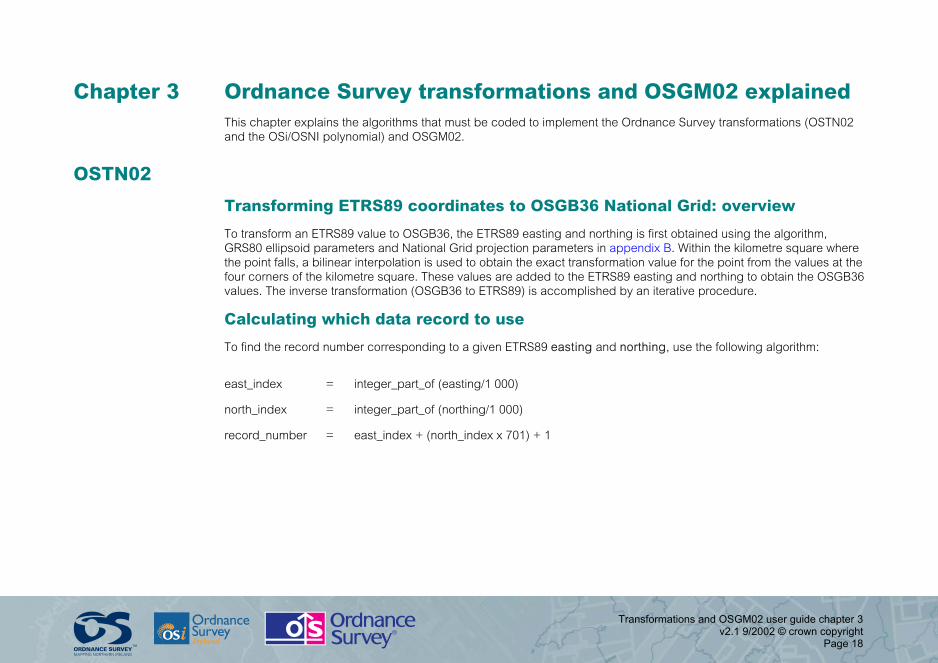
Chapter 3 Ordnance Survey transformations and OSGM02 explained This chapter explains the algorithms that must be coded to implement the Ordnance Survey transformations (OSTN02 and the OSi/OSNI polynomial) and OSGM02.
OSTN02
Transforming ETRS89 coordinates to OSGB36 National Grid: overview
To transform an ETRS89 value to OSGB36, the ETRS89 easting and northing is first obtained using the algorithm, GRS80 ellipsoid parameters and National Grid projection parameters in appendix B. Within the kilometre square where the point falls, a bilinear interpolation is used to obtain the exact transformation value for the point from the values at the four corners of the kilometre square. These values are added to the ETRS89 easting and northing to obtain the OSGB36 values. The inverse transformation (OSGB36 to ETRS89) is accomplished by an iterative procedure.
Calculating which data record to use
To find the record number corresponding to a given ETRS89 easting and northing, use the following algorithm:
east_index = integer_part_of (easting/1 000)
north_index = integer_part_of (northing/1 000)
record_number = east_index + (north_index x 701) + 1

Transformations and OSGM02 user guide chapter 3 v2.1 9/2002 © crown copyright
Page 19
For example, to find the record for (2 000E, 1 000N):
east_index = integer_part_of (2 000/1 000)
= 2
north_index = integer_part_of (1 000/1 000)
= 1
record_number = east_index + (north_index x 701) + 1
= 2 + 1 x 701 + 1
= 704
Procedure for transforming ETRS89 to OSGB36 coordinates
To convert an ETRS89 easting and northing (x, y) obtained using appendix B to a National Grid easting and northing (e, n), the easting and northing shifts from the data file should be added to the x and y coordinates, respectively.
The point to be transformed is unlikely to lie exactly on one of the nodes of the grid, so to calculate the shifts at any other points an interpolation is required.
The first stage in the transformation is to identify in which grid cell the ETRS89 point lies. This simply requires an integer division of the (x, y) coordinates, where x and y are in metres:
east_index = integer_part_of (x/1 000)
north_index = integer_part_of (y/1 000)
Having located the correct cell, find the values of the shifts at the four corners of the cell ( se0 se1, se2, se3 for the shifts in eastings, and sn0, sn1, sn2, sn3 for the shifts in northings) and the offsets of the point x, y from the bottom left corner of the cell (x0, y0) – shown in figure 1 below (the sg values in the figure are used to find the vertical shift values from OSGM02 later on).

Transformations and OSGM02 user guide chapter 3 v2.1 9/2002 © crown copyright
Page 20
Figure 1: Calculating the OSTN02 se and sn horizontal shifts and the sg vertical shifts for OSGM02.
x,y
dx
dy
y0
x0
se0, sn0, sg0 se1, sn1, sg1
se3, sn3, sg3 se2, sn2, sg2

Transformations and OSGM02 user guide chapter 3 v2.1 9/2002 © crown copyright
Page 21
Shifts for x, y are: se0 = east_shift(east_index, north_index)
NOTE: recall that the record number in the data file will be (east_index+(north_index x 701) + 1)
se1 = east_shift(east_index + 1, north_index) se2 = east_shift(east_index + 1, north_index + 1) se3 = east_shift(east_index, north_index + 1)
sn0 = north_shift(east_index, north_index) sn1 = north_shift(east_index + 1, north_index) sn2 = north_shift(east_index + 1, north_index + 1) sn3 = north_shift(east_index, north_index + 1)
Offsets are:
dx = x – x0 dy = y – y0
The value of the east shift (se), north shift (sn) at the point x, y is given by the following formulae:
t =dx /1 000 u =dy /1 000
se =(1 – t)(1 – u) se0 + ( t)(1 – u) se1 + ( t) ( u)se2 + (1 – t)( u) se3 sn =(1 – t)(1 – u) sn0 + ( t)(1 – u) sn1 + ( t) ( u)sn2 + (1 – t)( u) sn3
These shifts must then be added to the point x, y to give the National Grid position (e, n):
e = x + se n = y + sn

Transformations and OSGM02 user guide chapter 3 v2.1 9/2002 © crown copyright
Page 22
Inverse transformation (OSGB36 to ETRS89)
To compute ETRS89 eastings and northings from OSGB36 coordinates, an iterative procedure is required:
Step 1
To start the iteration, compute the ETRS89–OSGB36 easting and northing shifts at the OSGB36 point, using the OSGB36 easting and northing and the method described in procedure for transforming coordinates (page 20).
Subtract these shifts from the OSGB36 coordinates to obtain the first estimate of the ETRS89 easting and northing.
Step 2
Use this estimate of the ETRS89 easting and northing to obtain improved values for the easting and northing shifts, and subtract these from the OSGB36 coordinates to obtain improved values of the ETRS89 easting and northing.
Step 3
If the difference between the first shift value and second shift value is more than 0.0001 metres in either easting or northing, repeat step 2 until this is not the case.
Step 4
If ETRS89 latitude and longitude coordinates are required, obtain these from the ETRS89 easting and northing by the procedure described in appendix C.

Transformations and OSGM02 user guide chapter 3 v2.1 9/2002 © crown copyright
Page 23
The OSi/OSNI polynomial transformation To some extent distortions within traditional triangulation networks are inevitable. Within the triangulation network of the Republic of Ireland and Northern Ireland these distortions are not generally significant; however, regional distortions do occur. A 3rd order polynomial transformation has been developed to model these distortions.
A polynomial expression was fitted to the coordinate differences of a number of points in the different coordinate reference systems. This is a one-dimensional fitting method that is applied to the geographical coordinate, requiring independent parameters to be computed for both latitude and longitude.
In general, the polynomial model can be expressed as:
∆φ =∑∑ Α i j (φ−φ m) i (λ−λ m) j ∆ λ=∑∑ Β i j (φ−φ m) i(λ−λ m) j
The fully expanded forms of the 3rd order polynomial are as follows:
∆φ = [A00 + A10U + A01V + A11UV + A20U2 + A02V2 + A21U2V + A12UV2 + A22U2V2 + A30U3 + A03V3 + A31U3V + A13UV3 + A32U3V2 + A23U2V3 + A33U3V3] / 3600
∆λ = [B00 + B10U + B01V + B11UV + B20U2 + B02V2 + B21U2V + B12UV2 + B22U2V2+ A30U3 + B03V3 + B31U3V + B13UV3 + B32U3V2 + B23U2V3 + B33U3V3] / 3600
Where Aij and Bij are the computed parameters, and U and V are the normalised coordinates calculated as follows:
U = k0 (φ - φm) and V = k0 (λ - λm)
Where φm and λm are the coordinates of the approximate centre of the region. The parameters Aij, Bij,K0 , φ m and λm are given in table 2 below. The transformed geographical coordinates are then obtained as follows:
λETRS = λIG + ∆λ and φETRS = φIG + ∆φ
The reverse transformation from ETRS89 to Irish Grid cannot be calculated directly and requires iteration.
Conversions between geographical and grid coordinates are computed using standard Transverse Mercator projection formulae in association with the published Irish Grid parameters.

Transformations and OSGM02 user guide chapter 3 v2.1 9/2002 © crown copyright
Page 24
Table of coefficients for OSi/OSNI polynomial transformation
Coefficient i, j Latitude (Ai, j) Longitude (Bi, j)
0, 0 0.763 -2.810
0, 1 0.123 -4.680
0, 2 0.183 0.170
0, 3 -0.374 2.163
1, 0 -4.487 -0.341
1, 1 -0.515 -0.119
1, 2 0.414 3.913
1, 3 13.110 18.867
2, 0 0.215 1.196
2, 1 -0.570 4.877
2, 2 5.703 -27.795
2, 3 113.743 -284.294
3, 0 -0.265 -0.887
3, 1 2.852 -46.666
3, 2 -61.678 -95.377
3, 3 -265.898 -853.950
Other parameters φ m = 53.5 λm = -7.7 K0 = 0.1

Transformations and OSGM02 user guide chapter 3 v2.1 9/2002 © crown copyright
Page 25
The Ordnance Survey Geoid model: OSGM02 Orthometric height (h) in the UK and Ireland can be found by the formula:
h = H - N
Where H is the GRS80 ellipsoidal height, and N is the geoid undulation (geoid-ellipsoid separation). Please note: some publications use the notations of h and H the other way round.
OSGM02 uses a grid look-up method, with geoid undulation interpolated from a 1 km grid covering the UK and the Republic of Ireland.
Similar to the Ordnance Survey (Great Britain) OSTN02 transformation, the first stage in calculating the geoid undulation is to identify in which grid cell the ETRS89 point lies. To identify the appropriate grid cell and record numbers in the GB data set follow the procedure given earlier in 'Transforming ETRS89 coordinates to OSGB36 National Grid'.
To identify the appropriate grid cell and record numbers in the Northern Ireland dataset, use the following formulae:
east_index = (integer_part_of (x/1000)) -550 north_index = (integer_part_of (y/1000)) -800 record_number = east_index + (north_index x 251) +1
To identify the appropriate grid cell and record numbers in the Republic of Ireland dataset, use:
east_index = (integer_part_of (x/1000)) -400 north_index = (integer_part_of (y/1000)) -500 record_number = east_index + (north_index x 351) +1
For both Irish datasets the ETRS89 eastings (x) and ETRS89 northings (y) must be computed using the GRS80 ellipsoid and ITM projection (see appendix B).
Having located the correct cell, find the values of the geoid undulations at the four corners of the cell (sg0, sg1, sg2, sg3) and the offsets of the point (dx, dy) from the bottom left corner of the cell (x0, y0) – as shown in figure 1 above (the se and sn values are used to find the OSTN02 eastings and northings shifts).

Transformations and OSGM02 user guide chapter 3 v2.1 9/2002 © crown copyright
Page 26
The value of the geoid undulation at point x, y is given as follows:
N =(1 – t)(1 – u) sg0 + ( t)(1 – u) sg1 + ( t) ( u)sg2 + (1 – t)( u) sg3
Where: t =dx /1 000 and u =dy /1 000
The resulting geoid undulation is subtracted from the ellipsoidal height (H) to give orthometric height (h).

Transformations and OSGM02 user guide chapter 4 v2.1 9/2002 © crown copyright
Page 27
Chapter 4 Quality statement
Coverage OSTN02 covers Great Britain and the Isle of Man. The OSi/OSNI polynomial transformation covers the Republic of Ireland and Northern Ireland. It should be noted that the Irish Grid and the National Grid are two independent coordinate reference systems, and that Irish Grid coordinates are not directly compatible with OSGB36 coordinates.
OSGM02 covers all of Great Britain, Isle of Man, Republic of Ireland, and Northern Ireland. The Geoid model comprises 14 patches in order to relate to mean sea level as defined by the specific vertical datum for each region. The datum flag that forms part of each data record specifies to which datum the geoid-ellipsoid separation value relates.
Both models have been cookie cut to a boundary that extends 10 km offshore and 2 km beyond the Northern Ireland/Republic of Ireland border. Any point outside this boundary will return null values in the shift and datum flag records. It is strongly suggested that any software written to incorporate this data be capable of recognising a null value and to return an outside of model boundary error message.
Within Ireland and Northern Ireland, OSGM02 returns orthometric heights relative to the Malin Head and Belfast Lough datums respectively. OSGM02 will return orthometric height relative to either the Malin Head or the Belfast Lough datums for points within 2 km of the border between the Republic of Ireland and Northern Ireland.
Accuracy of Ordnance Survey transformations Within Great Britain, OSTN02 is the definitive OSGB36/ETRS89 transformation. OSTN02 in combination with the ETRS89 coordinates of the active GPS network stations, rather than the fixed triangulation network, now define the National Grid. This means that, for example, the National Grid coordinates of an existing OSGB36 point, refixed using GPS from the National GPS Network and OSTN02, will be the correct ones. The original archived OSGB36 National Grid coordinates of the point (if different) will no longer be true OSGB36, by definition, but the two coordinates (new and archived) will agree on average to better than 0.1 m, (68% probability).
Within the Republic of Ireland and Northern Ireland the OSi/OSNI polynomial transformation is recommended for coordinate transformations between Irish Grid and ETRS89. Transformed ETRS89 coordinates will agree with Irish Grid coordinates derived from traditional survey control to within 0.4 m (95% data).

Transformations and OSGM02 user guide chapter 4 v2.1 9/2002 © crown copyright
Page 28
Accuracy of OSGM02 The heights output by precise GPS positioning in the ETRS89 coordinate system are geometric distance above the WGS84 (GRS80) reference ellipsoid. Note that GPS heights are typically two to three times less precise than horizontal positions. OSGM02 converts GPS ellipsoid heights to orthometric heights above mean sea level.
In mainland Great Britain, the datum (origin point) representing mean sea level is Ordnance Datum Newlyn, defined at Newlyn in Cornwall. In the Republic of Ireland, Northern Ireland, and the islands surrounding Great Britain, mean sea level is defined by specific independent vertical datums that are all incorporated in OSGM02 and hence OSGM02 is compatible with the products from each of the Ordnance Surveys. Other geoid models may give mean sea level heights that are incompatible with the Ordnance Surveys' products.
The estimated accuracies of OSGM02 for each regional vertical datum are included in the table below. The figures quoted assume precise ellipsoidal heights are used; for lower quality GPS observations additional error budget must be included.
Regional datum Standard error (m)
Great Britain 0.02
Republic of Ireland 0.03
Northern Ireland 0.02
Orkney 0.08
Shetland 0.03
Outer Hebrides 0.09
Isle of Man 0.03
St Kilda 0.06
Any discrepancy found between an Ordnance Survey levelled bench mark and a OSGM02 computed orthometric height is likely to be due to bench mark subsidence or uplift and, assuming precise GPS survey has been carefully carried out, the orthometric height given by OSGM02 should be considered correct in preference to archive bench mark heights.

Transformations and OSGM02 user guide appendix A v2.1 9/2002 © crown copyright
Page 29
Appendix A Transforming ETRS89 GPS coordinates to OSGB36 and orthometric height Worked example
To convert the coordinates of Caister Water Tower (at position given by ETRS89 geographical coordinates 52° 39' 28.8282" N, 1° 42' 57.8663" E, 108.05 m) to OSGB36 and orthometric height.
Step 1: Compute ETRS89 eastings and northings – see appendix B
Latitude = 52° 39' 28.8282" N = 52.658007833° N
Longitude = 1° 42' 57.8663" E = 1.716073973° E
The parameters for the GRS80 ellipsoid are:
a = 6 378 137.000 b = 6 356 752.314
Following the procedure in appendix B, the calculation steps yield the following:
e2 = 6.69437999e–03 ν = 6.38912542e+06 ρ = 6.37332179e+06 η2 = 2.47965408e-03 M = 4.06772557e+05 P = 6.48577261e–02 I = 3.06772557e+05 II = 1.54055171e+06 III = 1.56081387e+05 IIIA = –2.06739447e+04 IV = 3.87545974e+06 V = –1.70023086e+05 VI = –1.01356325e+05 eastings = 651 307.0031 northings = 313 255.6859

Transformations and OSGM02 user guide appendix A v2.1 9/2002 © crown copyright
Page 30
The ETRS89 eastings and northings (to the nearest mm) are therefore:
x = 651 307.003 y = 313 255.686
Step 2: Convert ETRS89 eastings and northings to OSGB36 and ETRS89 height to orthometric height
First calculate the grid cell in which the point lies:
east_index = integer_part_of (x/1 000) = 651
north_index = integer_part_of (y/1 000) = 313
The eastings and northings of the south-west corner of the cell are therefore:
x0, y0 = (651 000, 313 000)
The easting, northing and geoid shifts for the four corners of the cell are given by:
( se0, sn0, sg0) = shifts (east_index, north_index) = shifts (651,313) = record (651 + (313 x 701) +1) = record (220 065) = (102.775, – 78.244, 44.252)
( se1, sn1, sg1) = shifts (652, 313) = record (220 066) = (102.813, –78.246, 44.236)
( se2, sn2, sg2) = shifts (652, 314) = record (220 767) = (102.822, –78.227, 44.224)
( se3, sn3, sg3) = shifts (651, 314) = record (220 766) = (102.783, –78.216, 44.240)

Transformations and OSGM02 user guide appendix A v2.1 9/2002 © crown copyright
Page 31
The offset values are given by:
dx = x – x0
= 307.0032
dy = y – y0
= 255.6860
t = dx/1 000 = 0.3070032
u = dy/1 000 = 0.2556860
The shifts are therefore:
se = (1 – t)(1 – u) se0 + ( t)(1 – u) se1 + ( t)( u) se2 + ( 1 – t)( u) se3
= 102.789
sn = (1 – t)(1 – u) sn0 + ( t)(1 – u) sn1 + ( t)( u) sn2 + (1 – t)( u) sn3
= -78.238
sg = (1 – t)(1 – u) sg0 + ( t)(1 – u) sg1 + ( t)( u) sg2 + (1 – t)( u) sg3
= 44.244
And finally, the National Grid (OSGB36) eastings and northings coordinates are given by:
e = x + se = 651 409.792
n = y + sn = 313 177.448
The orthometric height h is given by
h = 108.05 - sg = 108.05 – 44.244 = 63.806

Transformations and OSGM02 user guide appendix A v2.1 9/2002 © crown copyright
Page 32
So Caister Water Tower has National Grid (OSGB36) coordinates (651 409.792, 313 177.448) and orthometric height 63.806 m relative to the vertical datum as indicated by the datum flag field – which in this case = 1, indicating Ordnance Survey Datum Newlyn.
Using the procedure in appendix C, these coordinates can be converted to latitude and longitude. A worked example of this step is given in appendix C.
Inverse transformation: OSGB36 to ETRS89
Worked example
Taking the OSGB36 coordinates from the example above, that is 651 409.792, 313 177.448, the procedure for the inverse transformation (OSGB36 to ETRS89) gives the following iterative solution:
First values of OSGB36 to ETRS89 shifts: -102.792064 east, 78.240505 north.
First values of ETRS89 easting and northing: 651 306.999936 east, 313 255.688505 north.
Second values of OSGB36 to ETRS89 shifts: -102.788790 east, 78.238161 north.
Second values of ETRS89 easting and northing: 651 307.003210 east, 313 255.686161 north.
Third values of OSGB36 to ETRS89 shifts: -102.788790 east, 78.238161 north.
Third values of ETRS89 easting and northing: 651 307.003210 east, 313 255.686161 north.
Since the second and third iterations show convergence at the required level, the calculation is stopped.
Feeding the ETRS89 coordinates (651 307.003210, 313 255.686161) back into the procedure for transforming coordinates gives the OSGB36 coordinates (651 409.792000, 313 177.448000), showing that, for this example, applying the algorithm in both directions gives the values that were started with.
To calculate the GRS80 ellipsoidal height from the orthometric height simply add the geoid-ellipsoid separation.

Transformations and OSGM02 user guide appendix B v2.1 9/2002 © crown copyright
Page 33
Appendix B Converting latitude and longitude to easting and northing The formulae in this appendix and appendix C require ellipsoid constants and projection constants, given in the tables below.
Important note: When converting OSGB36 coordinates between (easting, northing) and (latitude, longitude) in either direction, use the Airy 1830 ellipsoid constants. When converting ETRS89 coordinates between (easting, northing) and (latitude, longitude) in either direction, use the GRS80 ellipsoid constants. Use the same National Grid projection constants for both ETRS89 and OSGB36 coordinates.
The ITM (Irish Transverse Mercator) projection is required to obtain ETRS89 eastings and ETRS89 northings for use with the OSGM02 Geoid model data files for Northern Ireland and the Republic of Ireland. The ITM projection should only be used with the GRS80 ellipsoid.
Ellipsoid constants
Ellipsoid Semi-major axis a (metres)
Semi-minor axis b (metres)
Used for the following coordinate
system
Airy 1830 6 377 563.396 6 356 256.910 OSGB36 National Grid
GRS80‡ 6 378 137.000 6 356 752.3141 ETRS89 (WGS84)
‡ Also known as the WGS84 ellipsoid.
The ellipsoid squared eccentricity constant e2 is computed from a and b by:
2
222 �
abae = (B1)

Transformations and OSGM02 user guide appendix B v2.1 9/2002 © crown copyright
Page 34
Projection constants
Projection Scale factor on central
meridian (F0)
True origin (φ0 and λ0)
Map coordinates of true origin (m)
(E0 and N0)
National Grid
0.9996012717 lat 49° N long 2° W
E 400 000 N 100 000
ITM
0.99982 Lat 53° 30' N long 8° W
E 600 000 N 750 000
To convert a position from the graticule of latitude and longitude coordinates (λ, φ) to a grid of easting and northing coordinates (E, N) using a transverse mercator projection, for example OSGB36 National Grid, ITM or UTM (Universal Transverse Mercator), compute the following formulae. Remember to express all angles in radians. You will need the ellipsoid constants a, b and e2 and the projection constants listed below:
N0 – northing of true origin;
E0 – easting of true origin;
F0 – scale factor on central meridian;
φ0 – latitude of true origin; and
λ0 – longitude of true origin and central meridian.
baban
+−= (B2)
)sin(1 0.5220
−−= φeaFν (B3)
51222
0 sin11 .φ) e)(e(aFρ −−−= (B4)
12 −=ρν η (B5)

Transformations and OSGM02 user guide appendix B v2.1 9/2002 © crown copyright
Page 35
+−−+−
++
+−
++−−
+++
=))(3cos())(3sin(
2435))(2cos())(2sin(
815
815
)cos()sin(82133)(
45
451
003
0032
0032
032
0
φφφφφφφφ
φφφφφφ
nnn
nnnnnnFbM (B6)
0I NM +=
φφν cossin2
II =
)9tan5(cossin24
III 223 ηφφφν +−=
)tantan5861(cossin720
IIIA 425 φφφφν +−=
φν cosIV =
−= φ
ρνφν 23 tancos
6V
( )222425 tan5814tantan185cos120
VI ηφηφφφν −++−=
6
04
02
0 )(IIIA)III()(III λλλλλλ −+−+−+=N (B7)
5
03
000 )(VI)(V)(IV λλλλλλ −+−+−+= EE (B8)

Transformations and OSGM02 user guide appendix B v2.1 9/2002 © crown copyright
Page 36
Worked example using the Airy 1830 ellipsoid and National Grid Intermediate values are shown here to 10 decimal places. Compute all values using double-precision arithmetic.
φ 52° 39' 27.2531" N λ 1° 43' 4.5177" E
ν 6.3885023333e+06 ρ 6.3727564399e+06 η2 2.4708136169e–03 M 4.0668829596e+05 I 3.0668829596e+05 II 1.5404079092e+06 III 1.5606875424e+05 IIIA –2.0671123011e+04 IV 3.8751205749e+06 V –1.7000078208e+05 VI –1.0134470432e+05
E 651 409.903 m N 313 177.270 m

Transformations and OSGM02 user guide appendix C v2.1 9/2002 © crown copyright
Page 37
Appendix C Converting easting and northing to latitude and longitude Obtaining (λ, φ) from (E, N) is an iterative procedure. You need values for the ellipsoid and projection constants a, b, e2, N0, E0, F0, φ0 and λ0 given in appendix B. Remember to express all angles in radians.
First compute:
00
0 φφ +
−=′
aFNN
(C1)
and M from equation (B6) in appendix B, substituting φ′ for φ .
If the absolute value of (N – N0 – M) ≥ 0.01 mm, obtain a new value for φ′ using:
φφ ′+
−−=′
0
0
aFMNN
new (C2)
and recompute M substituting φ′ for φ .
Iterate until the absolute value of (N – N0 – M) < 0.01 mm, then compute ρ, ν and η2 using equations (B3, B4 and B5) in
appendix B and compute:
ρν
φ2tan
VII′
=
( )22223
tan9tan3524tanVIII ηφηφ
ρνφ ′−+′+
′=

Transformations and OSGM02 user guide appendix C v2.1 9/2002 © crown copyright
Page 38
( )φφρνφ ′+′+
′= 42
5 tan45tan9061720
tanIX
ν
φ ′= secX
′+′
φν
φ 23 tan2
6sec=XI
pv
( )φφνφ ′+′+
′ 425 tan24tan285
120sec=XII
( )φφφνφ ′+′+′+
′ 6427 tan720tan1320tan66261
5040sec=XIIA
6
04
02
0 )(IX)(VIII)(VII EEEEEE −−−+−−′= φφ (C3)
7
05
03
000 )(XIIA)(XII)()( EEEEEEXIEEX −−−+−−−+= λλ (C4)

Transformations and OSGM02 user guide appendix C v2.1 9/2002 © crown copyright
Page 39
Worked example using Airy 1830 ellipsoid and National Grid Intermediate values are shown here to 10 decimal places. Compute all values using double precision arithmetic.
E 651 409.903 m N 313 177.270 m
φ′ 9.2002324604e–01 rad
M 4.1290347144e+05
2nd φ′ 9.2006619470e–01 rad
M 4.1317717541e+05
3rd φ ′ 9.2006620953e-01 rad
M 4.1317726997e+05
final φ′ 9.2006620954e–01 rad
ν 6.3885233415e+06 m ρ 6.3728193094e+06 m η2 2.4642205195e–03 VII 1.6130562490e–14 VIII 3.3395547442e–28 IX 9.4198561719e–42 X 2.5840062509e–07 XI 4.6985969968e–21 XII 1.6124316622e–34 XIIA 6.6577316330e–48 φ 52° 39' 27.2531" N λ 1° 43' 4.5177" E

Transformations and OSGM02 user guide appendix D v2.1 9/2002 © crown copyright
Page 40
Appendix D Glossary The following is a list of technical terms used in this user guide, together with a fuller definition.
datum
A point, line, surface or set of these, with respect to which positions of objects can be stated as unique sets of coordinates.
de facto national standard
A national standard by adoption rather than legally enforced.
ellipsoid (biaxial)
The 3-D geometric figure obtained by rotating an ellipse about its minor axis. Used in geodesy to approximate the shape of the earth.
ETRF89
European Terrestrial Reference Frame 1989 – the Europe-fixed realisation of WGS84. Governed by EUREF as a standard reference frame for Europe.
ETRS89
European Terrestrial Reference System 1989 – a coordinate system that is the Europe-fixed precise version of WGS84. Governed by EUREF as the standard fixed reference system for Europe. ETRS89 is related to the state-of-the-art WGS84-consistent system ITRS2000 by a six-parameter kinematic transformation published by IERS.
EUREF
EUREF (European Reference Frame): a sub-commission of the International Association of Geodesy, Commission X.
geocentric datum
A reference system that uses the centre of mass of the earth as its origin; the popularity of these systems today derives from their usefulness in describing satellite orbits.

Transformations and OSGM02 user guide appendix D v2.1 9/2002 © crown copyright
Page 41
Geoid model
A model of the level surface which is closest to mean sea level over the oceans. This surface is continued under land as the fundamental reference surface for height measurement.
GPS
Global Positioning System – an outdoor positioning technique using a constellation of US Department of Defense satellites and a portable receiver to dynamically determine coordinates. For high precision, several receivers are used and their relative positions are determined.
GRS80
A global reference ellipsoid used in the WGS84 coordinate system. Also known as the WGS84 ellipsoid.
IERS
International Earth Rotation Service.
ITRF
International Terrestrial Reference Frame – the state-of-the-art global realisation of the WGS84 reference system, using observations from worldwide networks of active geodetic stations of the VLBI, SLR, GPS and DORIS techniques.
ODN
Ordnance Datum Newlyn – the levelling-based vertical reference frame for most of the British Isles, with a single tide gauge constraint in Newlyn in Cornwall.
OSGB36
Ordnance Survey Great Britain 1936 – the British horizontal mapping datum, observed by triangulation from 1936 and traditionally realised on the ground by triangulation stations. With the release of the definitive transformation, OSTN02, OSGB36 is now realised by the ETRS89 coordinates of the National GPS Network in conjunction with the OSTN02 transformation.

Transformations and OSGM02 user guide appendix D v2.1 9/2002 © crown copyright
Page 42
OSGM02
Ordnance Survey National Geoid Model 2002 – a gravimetric Geoid model that is aligned with the national height datums of Great Britain, Northern Ireland and Ireland.
OSTN02
Ordnance Survey National Grid Transformation 2002 – a grid shift type horizontal transformation between the ETRS89 datum and OSGB36 National Grid.
realisation
A spatial reference system made real on the ground by monumented points with estimated coordinates and errors.
transformation
A procedure to change from one coordinate system to another.
WGS84
World Geodetic System 1984 – the global geodetic reference system used to describe the position of GPS satellites and ground stations.