Embed Size (px)
Citation preview

Register your instrument! www.eppendorf.com/myeppendorf
TransferMan® 4m
Operating manual

Copyright© 2019 Eppendorf AG, Germany. All rights reserved, including graphics and images. No part of this publication may be reproduced without the prior permission of the copyright owner.
Leica® is a registered trademark of Leica Microsystems®, Germany.
Nikon® and Eclipse® are registered trademarks of Nikon Corporation, Japan.
Olympus® is a registered trademark of Olympus Corporation, Japan.
Zeiss® and Axiovert® are registered trademarks of CARL ZEISS AG, Germany.
Eppendorf® and the Eppendorf Brand Design are registered trademarks of Eppendorf AG, Germany.
TransferMan® 4m, FemtoJet® and Eppendorf PiezoXpert® are registered trademarks of Eppendorf AG, Germany.
Registered trademarks and protected trademarks are not marked in all cases with ® or ™ in this manual.
Prescription statementCaution: Federal law restricts the sale of this device by the order of a physician (see 21 CFR 801.109 (b)(1)).Operating manual TransferMan® 4mseeon p.Fig.Tab.p.English (EN)Operating manual
5191 900.016-05/022019

Table of contentsTransferMan® 4m
English (EN)3
Table of contents
1 Operating instructions. . . . . . . . . . . . . . . . . . . . . . . . . . . . . . . . . . . . . . . . . . . . . . . . 91.1 Using this manual . . . . . . . . . . . . . . . . . . . . . . . . . . . . . . . . . . . . . . . . . . . . . . 91.2 Danger symbols and danger levels . . . . . . . . . . . . . . . . . . . . . . . . . . . . . . . . . 9
1.2.1 Danger symbols . . . . . . . . . . . . . . . . . . . . . . . . . . . . . . . . . . . . . . . . 91.2.2 Danger levels . . . . . . . . . . . . . . . . . . . . . . . . . . . . . . . . . . . . . . . . . . 9
1.3 Symbols used . . . . . . . . . . . . . . . . . . . . . . . . . . . . . . . . . . . . . . . . . . . . . . . . . 9
2 Safety . . . . . . . . . . . . . . . . . . . . . . . . . . . . . . . . . . . . . . . . . . . . . . . . . . . . . . . . . . . . 102.1 Indications for use – U.S.A.. . . . . . . . . . . . . . . . . . . . . . . . . . . . . . . . . . . . . . 102.2 Intended use – European Union . . . . . . . . . . . . . . . . . . . . . . . . . . . . . . . . . . 102.3 Warnings for intended use . . . . . . . . . . . . . . . . . . . . . . . . . . . . . . . . . . . . . . 102.4 Warning signs on the device. . . . . . . . . . . . . . . . . . . . . . . . . . . . . . . . . . . . . 112.5 User profile . . . . . . . . . . . . . . . . . . . . . . . . . . . . . . . . . . . . . . . . . . . . . . . . . . 122.6 Information on product liability . . . . . . . . . . . . . . . . . . . . . . . . . . . . . . . . . . 12
3 Product description . . . . . . . . . . . . . . . . . . . . . . . . . . . . . . . . . . . . . . . . . . . . . . . . . 133.1 Delivery package . . . . . . . . . . . . . . . . . . . . . . . . . . . . . . . . . . . . . . . . . . . . . . 13
3.1.1 Tools . . . . . . . . . . . . . . . . . . . . . . . . . . . . . . . . . . . . . . . . . . . . . . . 133.1.2 Accessories . . . . . . . . . . . . . . . . . . . . . . . . . . . . . . . . . . . . . . . . . . 13
3.2 Features. . . . . . . . . . . . . . . . . . . . . . . . . . . . . . . . . . . . . . . . . . . . . . . . . . . . . 143.3 Product overview. . . . . . . . . . . . . . . . . . . . . . . . . . . . . . . . . . . . . . . . . . . . . . 15
3.3.1 Motor module . . . . . . . . . . . . . . . . . . . . . . . . . . . . . . . . . . . . . . . . 163.3.2 Microscope adapter . . . . . . . . . . . . . . . . . . . . . . . . . . . . . . . . . . . . 173.3.3 Control board. . . . . . . . . . . . . . . . . . . . . . . . . . . . . . . . . . . . . . . . . 193.3.4 Tools . . . . . . . . . . . . . . . . . . . . . . . . . . . . . . . . . . . . . . . . . . . . . . . 21
3.4 Control panel. . . . . . . . . . . . . . . . . . . . . . . . . . . . . . . . . . . . . . . . . . . . . . . . . 223.5 Joystick . . . . . . . . . . . . . . . . . . . . . . . . . . . . . . . . . . . . . . . . . . . . . . . . . . . . . 23
3.5.1 Proportional range. . . . . . . . . . . . . . . . . . . . . . . . . . . . . . . . . . . . . 243.5.2 Dynamic range. . . . . . . . . . . . . . . . . . . . . . . . . . . . . . . . . . . . . . . . 243.5.3 Direction of movement of the joystick. . . . . . . . . . . . . . . . . . . . . . 243.5.4 Direction of movement of the rotating wheel . . . . . . . . . . . . . . . . 253.5.5 Joystick key functions . . . . . . . . . . . . . . . . . . . . . . . . . . . . . . . . . . 25
3.6 Working range. . . . . . . . . . . . . . . . . . . . . . . . . . . . . . . . . . . . . . . . . . . . . . . . 253.7 Resulting speed. . . . . . . . . . . . . . . . . . . . . . . . . . . . . . . . . . . . . . . . . . . . . . . 27
4 Installation . . . . . . . . . . . . . . . . . . . . . . . . . . . . . . . . . . . . . . . . . . . . . . . . . . . . . . . . 284.1 Preparing installation . . . . . . . . . . . . . . . . . . . . . . . . . . . . . . . . . . . . . . . . . . 28
4.1.1 Complaints about damages . . . . . . . . . . . . . . . . . . . . . . . . . . . . . . 284.1.2 Incomplete delivery . . . . . . . . . . . . . . . . . . . . . . . . . . . . . . . . . . . . 284.1.3 Microscope adapter assembly . . . . . . . . . . . . . . . . . . . . . . . . . . . . 28
4.2 Selecting the location . . . . . . . . . . . . . . . . . . . . . . . . . . . . . . . . . . . . . . . . . . 29

4Table of contentsTransferMan® 4mEnglish (EN)
4.3 Mounting overview . . . . . . . . . . . . . . . . . . . . . . . . . . . . . . . . . . . . . . . . . . . . 294.3.1 Mounting with horizontal microscope adapter . . . . . . . . . . . . . . . 294.3.2 Mounting with vertical microscope adapter . . . . . . . . . . . . . . . . . 304.3.3 Module (X, Y, Z). . . . . . . . . . . . . . . . . . . . . . . . . . . . . . . . . . . . . . . 314.3.4 Z-module holder – horizontal microscope adapter . . . . . . . . . . . . 324.3.5 Slider . . . . . . . . . . . . . . . . . . . . . . . . . . . . . . . . . . . . . . . . . . . . . . . 324.3.6 Z-slider – vertical microscope adapter . . . . . . . . . . . . . . . . . . . . . 334.3.7 Angle head. . . . . . . . . . . . . . . . . . . . . . . . . . . . . . . . . . . . . . . . . . . 344.3.8 Swivel joint . . . . . . . . . . . . . . . . . . . . . . . . . . . . . . . . . . . . . . . . . . 35
4.4 Mounting the motor module . . . . . . . . . . . . . . . . . . . . . . . . . . . . . . . . . . . . . 354.4.1 Mounting the Z-module – horizontal microscope adapter . . . . . . 364.4.2 Mounting the Z-module – vertical microscope adapter . . . . . . . . 374.4.3 Mounting the Y-module. . . . . . . . . . . . . . . . . . . . . . . . . . . . . . . . . 374.4.4 Mounting the X-module . . . . . . . . . . . . . . . . . . . . . . . . . . . . . . . . 384.4.5 Mounting the angle head . . . . . . . . . . . . . . . . . . . . . . . . . . . . . . . 39
4.5 Inserting o-rings in the grip head . . . . . . . . . . . . . . . . . . . . . . . . . . . . . . . . . 404.6 Inserting the capillary holder into the angle head . . . . . . . . . . . . . . . . . . . . 41
4.6.1 Attaching the positioning aid . . . . . . . . . . . . . . . . . . . . . . . . . . . . 414.7 Inserting the capillary . . . . . . . . . . . . . . . . . . . . . . . . . . . . . . . . . . . . . . . . . . 424.8 Inserting Femtotips . . . . . . . . . . . . . . . . . . . . . . . . . . . . . . . . . . . . . . . . . . . . 434.9 Setting the injection angle . . . . . . . . . . . . . . . . . . . . . . . . . . . . . . . . . . . . . . 434.10 Aligning the motor module . . . . . . . . . . . . . . . . . . . . . . . . . . . . . . . . . . . . . . 43
4.10.1 Aligning the height . . . . . . . . . . . . . . . . . . . . . . . . . . . . . . . . . . . . 444.10.2 Aligning the depth . . . . . . . . . . . . . . . . . . . . . . . . . . . . . . . . . . . . . 444.10.3 Aligning the width . . . . . . . . . . . . . . . . . . . . . . . . . . . . . . . . . . . . . 444.10.4 Aligning the angle head. . . . . . . . . . . . . . . . . . . . . . . . . . . . . . . . . 45
4.11 Entering mounting parameters . . . . . . . . . . . . . . . . . . . . . . . . . . . . . . . . . . . 454.11.1 Microscope and adapter . . . . . . . . . . . . . . . . . . . . . . . . . . . . . . . . 454.11.2 Motor module – horizontal microscope adapter . . . . . . . . . . . . . . 464.11.3 Motor module – vertical microscope adapter . . . . . . . . . . . . . . . . 474.11.4 Angle head. . . . . . . . . . . . . . . . . . . . . . . . . . . . . . . . . . . . . . . . . . . 47
4.12 Converting the swivel joint for left side mounting . . . . . . . . . . . . . . . . . . . . 484.13 Converting the angle head for left side mounting . . . . . . . . . . . . . . . . . . . . 514.14 Connect the motor module to the control board. . . . . . . . . . . . . . . . . . . . . . 524.15 Setting installation parameters . . . . . . . . . . . . . . . . . . . . . . . . . . . . . . . . . . . 53
4.15.1 First set-up wizard. . . . . . . . . . . . . . . . . . . . . . . . . . . . . . . . . . . . . 54
5 Software . . . . . . . . . . . . . . . . . . . . . . . . . . . . . . . . . . . . . . . . . . . . . . . . . . . . . . . . . . 575.1 Display. . . . . . . . . . . . . . . . . . . . . . . . . . . . . . . . . . . . . . . . . . . . . . . . . . . . . . 57
5.1.1 Application display . . . . . . . . . . . . . . . . . . . . . . . . . . . . . . . . . . . . 575.1.2 Display of coordinates . . . . . . . . . . . . . . . . . . . . . . . . . . . . . . . . . . 585.1.3 Menu display . . . . . . . . . . . . . . . . . . . . . . . . . . . . . . . . . . . . . . . . . 59

Table of contentsTransferMan® 4m
English (EN)5
5.2 Applications. . . . . . . . . . . . . . . . . . . . . . . . . . . . . . . . . . . . . . . . . . . . . . . . . . 605.2.1 Application parameters . . . . . . . . . . . . . . . . . . . . . . . . . . . . . . . . . 605.2.2 Application – Cell transfer . . . . . . . . . . . . . . . . . . . . . . . . . . . . . . . 615.2.3 Application – ICSI . . . . . . . . . . . . . . . . . . . . . . . . . . . . . . . . . . . . . 615.2.4 Application – DNA injection . . . . . . . . . . . . . . . . . . . . . . . . . . . . . 625.2.5 Application – Basic . . . . . . . . . . . . . . . . . . . . . . . . . . . . . . . . . . . . 625.2.6 Application – My application. . . . . . . . . . . . . . . . . . . . . . . . . . . . . 63
5.3 Main menu . . . . . . . . . . . . . . . . . . . . . . . . . . . . . . . . . . . . . . . . . . . . . . . . . . 635.4 Navigating the menu. . . . . . . . . . . . . . . . . . . . . . . . . . . . . . . . . . . . . . . . . . . 64
5.4.1 Entering or changing parameters . . . . . . . . . . . . . . . . . . . . . . . . . 64
6 Operation . . . . . . . . . . . . . . . . . . . . . . . . . . . . . . . . . . . . . . . . . . . . . . . . . . . . . . . . . 656.1 Switching the device on or off . . . . . . . . . . . . . . . . . . . . . . . . . . . . . . . . . . . 65
6.1.1 Switching the device on . . . . . . . . . . . . . . . . . . . . . . . . . . . . . . . . 656.1.2 Switching off the device . . . . . . . . . . . . . . . . . . . . . . . . . . . . . . . . 65
6.2 Activating or deactivating the control board. . . . . . . . . . . . . . . . . . . . . . . . . 656.2.1 Activating the control board . . . . . . . . . . . . . . . . . . . . . . . . . . . . . 656.2.2 Deactivating the control board . . . . . . . . . . . . . . . . . . . . . . . . . . . 65
6.3 Defining the start screen. . . . . . . . . . . . . . . . . . . . . . . . . . . . . . . . . . . . . . . . 666.3.1 Defining the application . . . . . . . . . . . . . . . . . . . . . . . . . . . . . . . . 666.3.2 Defining the selected application . . . . . . . . . . . . . . . . . . . . . . . . . 66
6.4 Replacing the capillary . . . . . . . . . . . . . . . . . . . . . . . . . . . . . . . . . . . . . . . . . 666.4.1 Manually positioning the capillary . . . . . . . . . . . . . . . . . . . . . . . . 676.4.2 Automatically positioning the capillary . . . . . . . . . . . . . . . . . . . . . 67
6.5 Changing the sample . . . . . . . . . . . . . . . . . . . . . . . . . . . . . . . . . . . . . . . . . . 686.6 Changing the size of the working range . . . . . . . . . . . . . . . . . . . . . . . . . . . . 68
6.6.1 Change parameters using the selection dial . . . . . . . . . . . . . . . . . 686.6.2 Changing parameters in the menu . . . . . . . . . . . . . . . . . . . . . . . . 69
6.7 Shifting the movement range of the capillary. . . . . . . . . . . . . . . . . . . . . . . . 696.7.1 Extending the movement range into the dynamic range . . . . . . . 696.7.2 Uncoupling and resetting the joystick. . . . . . . . . . . . . . . . . . . . . . 69
6.8 Capillary positions. . . . . . . . . . . . . . . . . . . . . . . . . . . . . . . . . . . . . . . . . . . . . 706.8.1 Saving a position . . . . . . . . . . . . . . . . . . . . . . . . . . . . . . . . . . . . . . 706.8.2 Moving to the position using the softkey . . . . . . . . . . . . . . . . . . . 716.8.3 Moving to the position using the joystick key . . . . . . . . . . . . . . . . 716.8.4 Overwriting a stored position . . . . . . . . . . . . . . . . . . . . . . . . . . . . 716.8.5 Deleting a stored position . . . . . . . . . . . . . . . . . . . . . . . . . . . . . . . 72
6.9 Using the advanced storage function . . . . . . . . . . . . . . . . . . . . . . . . . . . . . . 726.10 Vertical limits . . . . . . . . . . . . . . . . . . . . . . . . . . . . . . . . . . . . . . . . . . . . . . . . 72
6.10.1 Defining the lower limit. . . . . . . . . . . . . . . . . . . . . . . . . . . . . . . . . 736.10.2 Deleting the lower limit . . . . . . . . . . . . . . . . . . . . . . . . . . . . . . . . . 736.10.3 Defining the upper limit . . . . . . . . . . . . . . . . . . . . . . . . . . . . . . . . 736.10.4 Deleting the upper limit. . . . . . . . . . . . . . . . . . . . . . . . . . . . . . . . . 73
6.11 Horizontal limit . . . . . . . . . . . . . . . . . . . . . . . . . . . . . . . . . . . . . . . . . . . . . . . 746.11.1 Defining the horizontal limit . . . . . . . . . . . . . . . . . . . . . . . . . . . . . 746.11.2 Deleting the horizontal limit . . . . . . . . . . . . . . . . . . . . . . . . . . . . . 74

6Table of contentsTransferMan® 4mEnglish (EN)
6.12 Speed function . . . . . . . . . . . . . . . . . . . . . . . . . . . . . . . . . . . . . . . . . . . . . . . 756.12.1 Speed menu and parameters. . . . . . . . . . . . . . . . . . . . . . . . . . . . . 756.12.2 Setting the parameter for Speed . . . . . . . . . . . . . . . . . . . . . . . . . . 75
6.13 Step injection function . . . . . . . . . . . . . . . . . . . . . . . . . . . . . . . . . . . . . . . . . 766.13.1 Step injection menu and parameters. . . . . . . . . . . . . . . . . . . . . . . 766.13.2 Executing the Step injection function . . . . . . . . . . . . . . . . . . . . . . 77
6.14 Home function. . . . . . . . . . . . . . . . . . . . . . . . . . . . . . . . . . . . . . . . . . . . . . . . 776.14.1 Home menu and parameters . . . . . . . . . . . . . . . . . . . . . . . . . . . . . 776.14.2 Setting the parameter for Home . . . . . . . . . . . . . . . . . . . . . . . . . . 786.14.3 Move the capillary out with the home key . . . . . . . . . . . . . . . . . . 786.14.4 Move the capillary back with the home key . . . . . . . . . . . . . . . . . 786.14.5 Setting the offset. . . . . . . . . . . . . . . . . . . . . . . . . . . . . . . . . . . . . . 786.14.6 Terminate the home function. . . . . . . . . . . . . . . . . . . . . . . . . . . . . 79
6.15 Clean function . . . . . . . . . . . . . . . . . . . . . . . . . . . . . . . . . . . . . . . . . . . . . . . . 796.15.1 Clean menu and parameters . . . . . . . . . . . . . . . . . . . . . . . . . . . . . 796.15.2 Setting the parameter for Clean . . . . . . . . . . . . . . . . . . . . . . . . . . 806.15.3 Execute the Clean function . . . . . . . . . . . . . . . . . . . . . . . . . . . . . . 806.15.4 Terminate the Clean function. . . . . . . . . . . . . . . . . . . . . . . . . . . . . 80
6.16 PiezoXpert function. . . . . . . . . . . . . . . . . . . . . . . . . . . . . . . . . . . . . . . . . . . . 816.16.1 PiezoXpert menu and parameters . . . . . . . . . . . . . . . . . . . . . . . . . 816.16.2 Execute the PiezoXpert function . . . . . . . . . . . . . . . . . . . . . . . . . . 82
6.17 Installation function . . . . . . . . . . . . . . . . . . . . . . . . . . . . . . . . . . . . . . . . . . . 826.17.1 Installation menu and parameters. . . . . . . . . . . . . . . . . . . . . . . . . 826.17.2 Installation parameters . . . . . . . . . . . . . . . . . . . . . . . . . . . . . . . . . 826.17.3 Control board parameters . . . . . . . . . . . . . . . . . . . . . . . . . . . . . . . 836.17.4 Joystick parameters . . . . . . . . . . . . . . . . . . . . . . . . . . . . . . . . . . . . 836.17.5 Module parameters . . . . . . . . . . . . . . . . . . . . . . . . . . . . . . . . . . . . 83
6.18 Function function . . . . . . . . . . . . . . . . . . . . . . . . . . . . . . . . . . . . . . . . . . . . . 846.18.1 Function menu and parameters. . . . . . . . . . . . . . . . . . . . . . . . . . . 846.18.2 Executing Zero coordin . . . . . . . . . . . . . . . . . . . . . . . . . . . . . . . . . 846.18.3 Executing Center motors. . . . . . . . . . . . . . . . . . . . . . . . . . . . . . . . 846.18.4 Executing User default . . . . . . . . . . . . . . . . . . . . . . . . . . . . . . . . . 85
6.19 Softkeys function. . . . . . . . . . . . . . . . . . . . . . . . . . . . . . . . . . . . . . . . . . . . . . 856.19.1 Softkeys menu and parameters . . . . . . . . . . . . . . . . . . . . . . . . . . . 856.19.2 Execute Softkeys . . . . . . . . . . . . . . . . . . . . . . . . . . . . . . . . . . . . . . 876.19.3 Execute Joystick key . . . . . . . . . . . . . . . . . . . . . . . . . . . . . . . . . . . 87
6.20 Change appl function . . . . . . . . . . . . . . . . . . . . . . . . . . . . . . . . . . . . . . . . . . 876.20.1 Change appl menu and parameters. . . . . . . . . . . . . . . . . . . . . . . . 876.20.2 Defining the application selection as the start screen. . . . . . . . . . 886.20.3 Defining an application as the start screen . . . . . . . . . . . . . . . . . . 88
6.21 Service function . . . . . . . . . . . . . . . . . . . . . . . . . . . . . . . . . . . . . . . . . . . . . . 886.21.1 Service menu and parameters . . . . . . . . . . . . . . . . . . . . . . . . . . . . 886.21.2 Executing the Selftest function . . . . . . . . . . . . . . . . . . . . . . . . . . . 89
6.22 Resetting parameters to the factory settings . . . . . . . . . . . . . . . . . . . . . . . . 896.22.1 Perform reset . . . . . . . . . . . . . . . . . . . . . . . . . . . . . . . . . . . . . . . . . 896.22.2 Carrying out a reset in the menu. . . . . . . . . . . . . . . . . . . . . . . . . . 89

Table of contentsTransferMan® 4m
English (EN)7
7 Troubleshooting . . . . . . . . . . . . . . . . . . . . . . . . . . . . . . . . . . . . . . . . . . . . . . . . . . . . 907.1 General errors . . . . . . . . . . . . . . . . . . . . . . . . . . . . . . . . . . . . . . . . . . . . . . . . 90
7.1.1 Motor module . . . . . . . . . . . . . . . . . . . . . . . . . . . . . . . . . . . . . . . . 907.1.2 Capillary. . . . . . . . . . . . . . . . . . . . . . . . . . . . . . . . . . . . . . . . . . . . . 907.1.3 Control board and display . . . . . . . . . . . . . . . . . . . . . . . . . . . . . . . 917.1.4 Joystick . . . . . . . . . . . . . . . . . . . . . . . . . . . . . . . . . . . . . . . . . . . . . 917.1.5 Software and parameters. . . . . . . . . . . . . . . . . . . . . . . . . . . . . . . . 91
7.2 Error messages . . . . . . . . . . . . . . . . . . . . . . . . . . . . . . . . . . . . . . . . . . . . . . . 927.2.1 Warnings . . . . . . . . . . . . . . . . . . . . . . . . . . . . . . . . . . . . . . . . . . . . 927.2.2 Error. . . . . . . . . . . . . . . . . . . . . . . . . . . . . . . . . . . . . . . . . . . . . . . . 92
8 Maintenance. . . . . . . . . . . . . . . . . . . . . . . . . . . . . . . . . . . . . . . . . . . . . . . . . . . . . . . 938.1 Replacing fuses . . . . . . . . . . . . . . . . . . . . . . . . . . . . . . . . . . . . . . . . . . . . . . . 938.2 Cleaning . . . . . . . . . . . . . . . . . . . . . . . . . . . . . . . . . . . . . . . . . . . . . . . . . . . . 938.3 Disinfection/decontamination . . . . . . . . . . . . . . . . . . . . . . . . . . . . . . . . . . . . 948.4 Service and maintenance . . . . . . . . . . . . . . . . . . . . . . . . . . . . . . . . . . . . . . . 94
9 Technical data . . . . . . . . . . . . . . . . . . . . . . . . . . . . . . . . . . . . . . . . . . . . . . . . . . . . . 959.1 Power supply. . . . . . . . . . . . . . . . . . . . . . . . . . . . . . . . . . . . . . . . . . . . . . . . . 969.2 Interfaces. . . . . . . . . . . . . . . . . . . . . . . . . . . . . . . . . . . . . . . . . . . . . . . . . . . . 969.3 Ambient conditions . . . . . . . . . . . . . . . . . . . . . . . . . . . . . . . . . . . . . . . . . . . . 96
10 Transport, storage and disposal . . . . . . . . . . . . . . . . . . . . . . . . . . . . . . . . . . . . . . . 9710.1 Disassembling and packing the micromanipulator. . . . . . . . . . . . . . . . . . . . 9710.2 Storage . . . . . . . . . . . . . . . . . . . . . . . . . . . . . . . . . . . . . . . . . . . . . . . . . . . . . 9910.3 Decontamination before shipment . . . . . . . . . . . . . . . . . . . . . . . . . . . . . . . . 9910.4 Transport . . . . . . . . . . . . . . . . . . . . . . . . . . . . . . . . . . . . . . . . . . . . . . . . . . . 10010.5 Disposal. . . . . . . . . . . . . . . . . . . . . . . . . . . . . . . . . . . . . . . . . . . . . . . . . . . . 100
11 Ordering information. . . . . . . . . . . . . . . . . . . . . . . . . . . . . . . . . . . . . . . . . . . . . . . 10111.1 Accessories for TransferMan 4m . . . . . . . . . . . . . . . . . . . . . . . . . . . . . . . . 10111.2 Microscope adapter . . . . . . . . . . . . . . . . . . . . . . . . . . . . . . . . . . . . . . . . . . 10111.3 CellTram 4m and accessories . . . . . . . . . . . . . . . . . . . . . . . . . . . . . . . . . . . 102
Index . . . . . . . . . . . . . . . . . . . . . . . . . . . . . . . . . . . . . . . . . . . . . . . . . . . . . . . . . . . . 103

8Table of contentsTransferMan® 4mEnglish (EN)

Operating instructionsTransferMan® 4m
English (EN)9
1 Operating instructions1.1 Using this manual
Read this operating manual thoroughly before using the device for the first time. Also observe the instructions for use of the accessories.
This operating manual is part of the product. It must always be kept easily accessible.Enclose this operating manual when transferring the device to third parties.You will find the current version of the operating manual for all available languages on
our website at www.eppendorf.com/manuals.
1.2 Danger symbols and danger levels1.2.1 Danger symbols
The safety instructions in this manual have the following danger symbols and danger levels:
1.2.2 Danger levels
1.3 Symbols used
Cuts Electric shock
Hazard point Material damage
DANGER Will lead to severe injuries or death.
WARNING May lead to severe injuries or death.
CAUTION May lead to light to moderate injuries.
NOTICE May lead to material damage.
Depiction Meaning
1.2.
Actions in the specified order
Actions without a specified order
• List
Text Display text or software text
Additional information

10SafetyTransferMan® 4mEnglish (EN)
2 Safety2.1 Indications for use – U.S.A.
The TransferMan 4m Micromanipulator is intended for use in assisted reproduction procedures requiring coarse and fine positioning of a microtool under the microscope.
2.2 Intended use – European Union
The TransferMan 4m was designed and manufactured for the purpose of intracytoplasmic sperm injection (ICSI) within the context of human reproductive medicine. Therefore the TransferMan 4m is a medical product in accordance with the guideline 93/42/EEC of the European Union. It shall only be used indoors and only by sufficiently trained specialists.
2.3 Warnings for intended use
WARNING! Risk of injury due to flying capillaries and glass splinters.If exposed to high pressures, capillaries may detach themselves from the grip heads and become projectiles.Capillaries can crack as a result of incorrect handling.
Wear protective goggles.Never aim capillaries at people.Use capillaries with an outer diameter that matches the grip head
specifications.Always mount / dismount capillaries when they are depressurized.Mount the capillary correctly in the grip head.Do not touch the capillary with the Petri dish or other objects.
CAUTION! Risk of cuts from broken capillaries.Capillaries are made of glass. They are very sharp and fragile.
Wear your personal protective equipment (PPE).Always mount capillaries depressurized.Never aim capillaries at people.Handle the capillaries very carefully.
NOTICE! Mechanical damage to the motor modules.Excessive load leads to increment errors or destruction of the drive.
Do not drive the modules against mechanical obstructions.Do not hold any objects near the modules.Load the motor module with a maximum of 200 g.

SafetyTransferMan® 4m
English (EN)11
2.4 Warning signs on the device
NOTICE! Device malfunctionDo not use mobile phones or other mobile communication equipment during operation.
Keep at least a distance of 2 meters.
WARNING! Damage to health due to infectious liquids and pathogenic germs.
When handling infectious liquids and pathogenic germs, observe the national regulations, the biosafety level of your laboratory, the Material Safety Data Sheets, and the manufacturer's application notes.
Wear your personal protective equipment.Consult the "Laboratory Biosafety Manual" (source: World Health
Organization, Laboratory Biosafety Manual, in its respectively current valid version).
Warning symbol Meaning
Warns of the risk of injury caused by capillary tips
Warns of the danger of crushing on the motor module
Warns of magnetic fields
Read the operating manual

12SafetyTransferMan® 4mEnglish (EN)
2.5 User profile
The device and accessories may only be operated by trained and skilled personnel.
Before using the device, read the operating manual carefully and familiarize yourself with the device's mode of operation.
2.6 Information on product liability
In the following cases, the designated protection of the device may be compromised. Liability for any resulting property damage or personal injury is then transferred to the operator:
• The device is not used in accordance with the operating manual.• The device is used outside of its intended use.• The device is used with accessories or consumables which are not recommended by
Eppendorf.• The device is maintained or repaired by individuals not authorized by Eppendorf.• The user makes unauthorized changes to the device.

Product descriptionTransferMan® 4m
English (EN)13
3 Product description3.1 Delivery package
3.1.1 Tools
3.1.2 Accessories
Quantity Description
1 X-module
1 Y-module
1 Z-module
1 YZ connector
1 Swivel joint
1 Angle head
1 Control board
1 Mains/power cord
1 Cable sheathing
1 Operating manual
1 Short instructions
1 Unpacking instructions
Quantity Description
7 Allen key, 1.5 mm, 2 mm, 2.5 mm, 3 mm, 4 mm, 5 mm, 6 mm
1 Allen torque screwdriver, 3 mm
1 Allen screwdriver, 1.3 mm
1 Tool bag
Quantity Description
2 Positioning aid for capillary holder
1 Spare parts kit
1 Label

14Product descriptionTransferMan® 4mEnglish (EN)
3.2 Features
The micromanipulator TransferMan 4m has been especially developed for work processes that require intuitive movement of the capillary.
The TransferMan 4m combines the classical benefits of a mechanical system with the benefits of an accurate electrically driven system.
The capillary is controlled by a joystick. The joystick has an inner (proportional) and an outer (dynamic) movement range. In the inner range, the joystick movement is transferred directly to the capillary. In the outer range, a greater forwards or backwards movement of the joystick results in an acceleration of the capillary movement. The movement ranges enable moving to any position in the working range of the micromanipulator.
Proportional movement is suitable for all working techniques that require intuitive, sensitive handling, e.g., intracytoplasmic sperm injection (ICSI) and the transfer of stem cells into blastocysts.
The software control provides predefined applications, freely programmable softkey functions, a freely programmable application and the storage of different positions in all space coordinates.
Product descriptionTransferMan® 4m
English (EN)15
3.3 Product overview
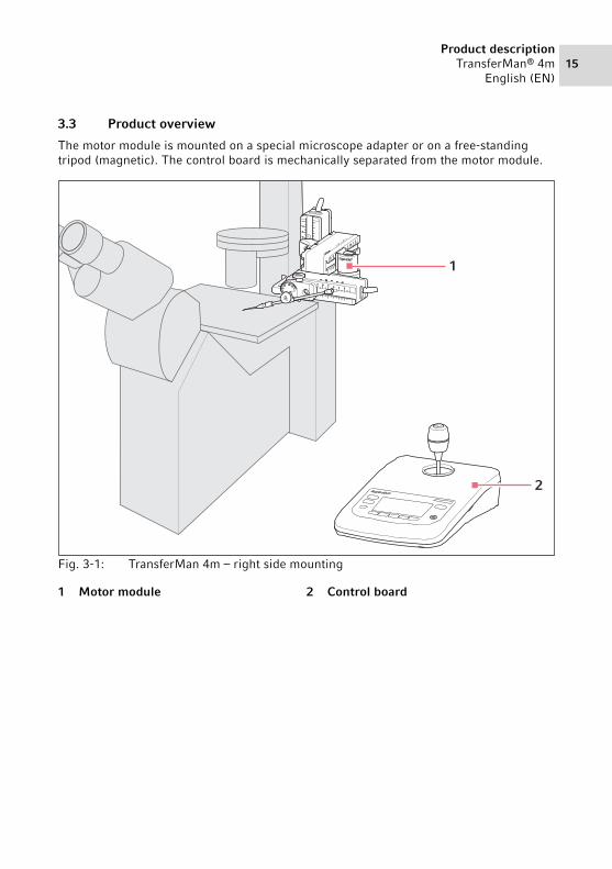
The motor module is mounted on a special microscope adapter or on a free-standing tripod (magnetic). The control board is mechanically separated from the motor module.Abb. 3-1:TransferMan 4m – right side mounting
Fig. 3-1: TransferMan 4m – right side mounting
1 Motor module 2 Control board
1
2
16Product descriptionTransferMan® 4mEnglish (EN)
3.3.1 Motor module
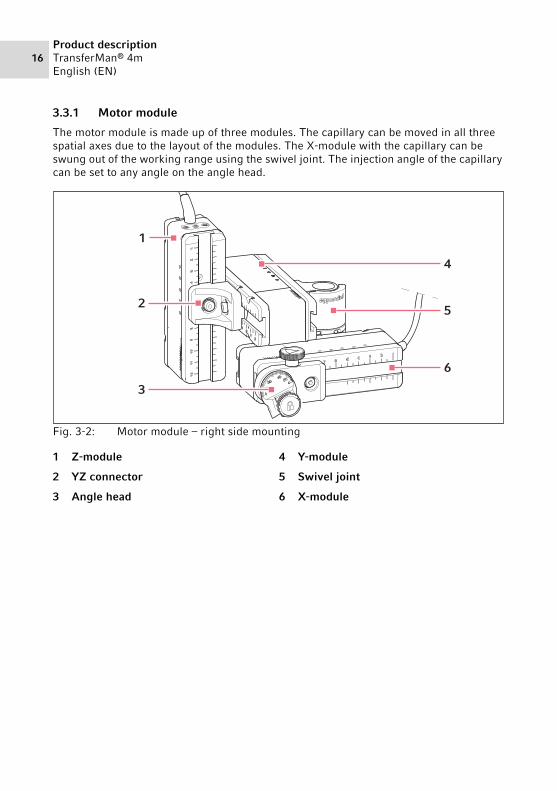
The motor module is made up of three modules. The capillary can be moved in all three spatial axes due to the layout of the modules. The X-module with the capillary can be swung out of the working range using the swivel joint. The injection angle of the capillary can be set to any angle on the angle head.Abb. 3-2:Motor module – right side mounting
Fig. 3-2: Motor module – right side mounting
1 Z-module
2 YZ connector
3 Angle head
4 Y-module
5 Swivel joint
6 X-module
1
2
3
4
5
6

Product descriptionTransferMan® 4m
English (EN)17
3.3.2 Microscope adapter
The motor module is mounted to a microscope adapter. A special microscope adapter is available for each microscope type. The microscope adapters are either mounted horizontally or vertically.
Abb. 3-3:Microscope adapter for horizontal mounting – example: Olympus 1
Fig. 3-3: Microscope adapter for horizontal mounting – example: Olympus 1
The microscope adapter is not included in the delivery package.
1 Designation with identification of the microscope type
2 Cable conduit
3 Z-module holderFor horizontally mounted microscope adapters
2
1 3
18Product descriptionTransferMan® 4mEnglish (EN)
Abb. 3-4:Microscope adapter for vertical mounting – example: Nikon 1
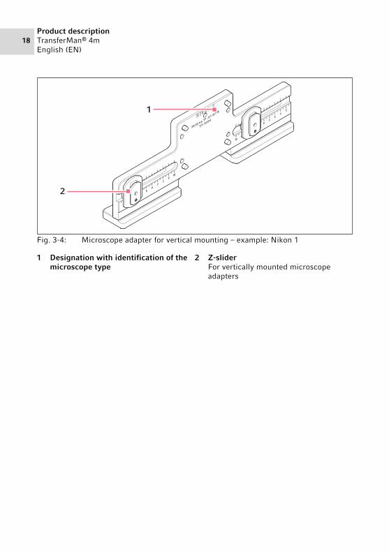
Fig. 3-4: Microscope adapter for vertical mounting – example: Nikon 1
1 Designation with identification of the microscope type
2 Z-sliderFor vertically mounted microscope adapters
1
2
Product descriptionTransferMan® 4m
English (EN)19
3.3.3 Control board
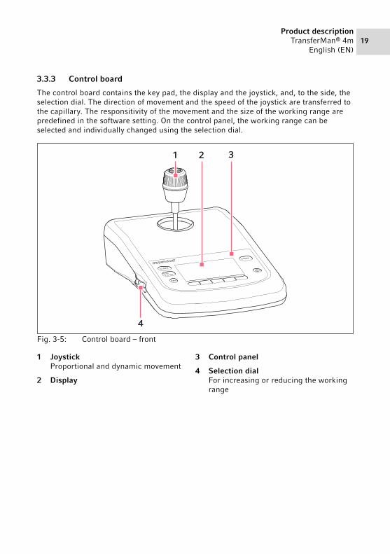
The control board contains the key pad, the display and the joystick, and, to the side, the selection dial. The direction of movement and the speed of the joystick are transferred to the capillary. The responsitivity of the movement and the size of the working range are predefined in the software setting. On the control panel, the working range can be selected and individually changed using the selection dial.Abb. 3-5:Control board – front
Fig. 3-5: Control board – front
1 JoystickProportional and dynamic movement
2 Display
3 Control panel
4 Selection dialFor increasing or reducing the working range
home
menu
finefine
coarse
4
1 2 3

20Product descriptionTransferMan® 4mEnglish (EN)
Abb. 3-6:Control board – rear
Fig. 3-6: Control board – rear
1 Mains/power switch On/Off
2 Micro fuse
3 Mains/power connection
4 Service connection
5 Connection for a Z-module
6 Connection for an X-module
7 Connection for a Y-module
8 Connection for an external deviceFoot control, FemtoJet, FemtoJet express or PiezoXpert
X-Axis
Y-Axis
ext. Device
Z-Axis
SERVICE
65432
17
8

Product descriptionTransferMan® 4m
English (EN)21
3.3.4 ToolsAbb. 3-7:Tools
Fig. 3-7: Tools
1 Allen torque screwdriver3 mm
2 Allen screwdriver 1.3 mm
3 Allen key1.5 mm, 2 mm, 2.5 mm, 3 mm, 4 mm, 5 mm, 6 mm
1
2
3

22Product descriptionTransferMan® 4mEnglish (EN)
3.4 Control panel
With the keys on the control panel you can switch on the control board and select the size of the working range. The softkeys are used to open applications, execute functions, navigate the menu and set parameters.Abb. 3-8:Control panel
Fig. 3-8: Control panel
1 coarse keySets the large working range
2 fine/x-fine keySets the medium or small working range
3 menu keyOpens the menu
4 Softkeys 1 – 5Select an application, trigger a function, navigate or set parameter values
5 standby keySwitches the control board on or off or cancels automatic movements
6 DisplayDisplays the software
7 home keyMoves the capillary out of the working range to a defined position
homecoarse
fine
x–fine
menu
7
6
5
1
2
3
4

Product descriptionTransferMan® 4m
English (EN)23
3.5 Joystick
The joystick moves the capillary in all three spatial axes. The joystick movement is transferred directly to the capillary in the proportional range. In the dynamic range, the movement of the capillary is accelerated the further the joystick is moved forwards and backwards.Abb. 3-9:Joystick
Fig. 3-9: Joystick
Abb. 3-10:Movement ranges of the joystick
Fig. 3-10: Movement ranges of the joystick
1 Joystick key
2 SwivelControls movements in the Z-axis
3 Lower partControls movements in the X and Y-axis
1 Proportional range 2 Dynamic range
12
3
1
2
24Product descriptionTransferMan® 4mEnglish (EN)
3.5.1 Proportional range
In the proportional range, the capillary will move as quickly or slowly as the joystick is moved. The travel of the capillary is also proportional to the distance that the joystick has been moved forwards and backwards. The movement of the capillary will stop as soon as the joystick is no longer moved or when the position is reached at which the joystick was stopped. There is a noticeable stop on the outer limit of the proportional range. This stop is in a narrow zone in which moving the joystick sideways does not result in any further movement of the capillary.
The size of the proportional range depends on the working range selected.
3.5.2 Dynamic range
After the stop, the dynamic range of the joystick begins: When the joystick is moved against the spring-loaded stop, the capillary starts moving in the direction of the joystick movement. The movement stops when the joystick is released and it drops back into the zone due to the spring force of the stop. The speed of the capillary in the dynamic range is increased dynamically by a stronger pressure against the stop.
The size of the dynamic range is limited by the movement range of the modules (X and Y).
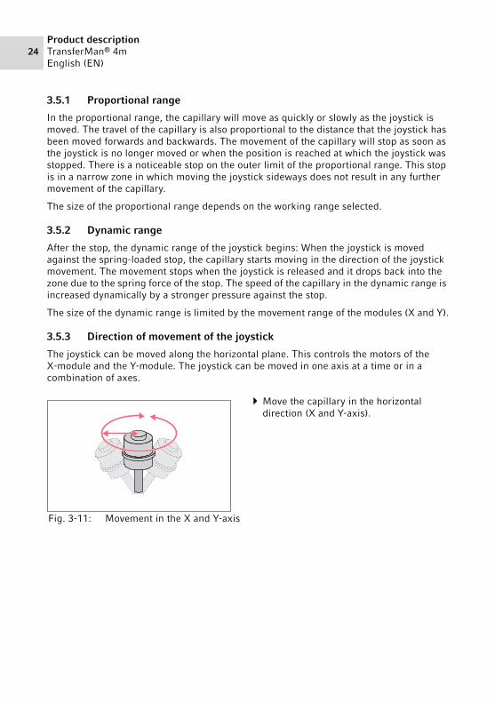
3.5.3 Direction of movement of the joystick
The joystick can be moved along the horizontal plane. This controls the motors of the X-module and the Y-module. The joystick can be moved in one axis at a time or in a combination of axes.
Abb. 3-11:Movement in the X and Y-axis
Fig. 3-11: Movement in the X and Y-axis
Move the capillary in the horizontal direction (X and Y-axis).

Product descriptionTransferMan® 4m
English (EN)25
3.5.4 Direction of movement of the rotating wheel
The rotating wheel on the joystick moves the motor module in the vertical axis. This activates the motor of the Z-module.
3.5.5 Joystick key functions
3.6 Working range
There are three working ranges within the movement range of the joystick. For each working range, a radius with a resulting speed ratio is preset. The radius can be set using the selection dial on the control board and in the Speed menu.
Working ranges:• coarse – for a large working range• fine – for a medium working range• x-fine – for a small working range
Abb. 3-12:Movement in the Z-axis
Fig. 3-12: Movement in the Z-axis
Move the capillary in the vertical direction (Z-axis).
Abb. 3-13:No movement of the capillary
Fig. 3-13: No movement of the capillary
Uncouple the joystick from the motor module.
Trigger functions (e.g., switch between saved positions).

26Product descriptionTransferMan® 4mEnglish (EN)
Abb. 3-14:Large working range – coarse
Fig. 3-14: Large working range – coarse
Move capillary over a large distance.Position capillary roughly and quickly.
Abb. 3-15:Medium working range – fine
Fig. 3-15: Medium working range – fine
Move capillary over a medium distance.Position capillary precisely.
Abb. 3-16:Small working range – x-fine
Fig. 3-16: Small working range – x-fine
Move capillary over a very short distance.
Position capillary very precisely and slowly.
Active for x-fine working range larger than 0.

Product descriptionTransferMan® 4m
English (EN)27
3.7 Resulting speed
In the inner (proportional) range, the speed of the capillary is dependent on the speed at which the joystick is moved forwards and backwards and the size of the set working range. If the joystick is moved forwards and backwards at the same speed with, e.g., the setting fine or coarse, the resulting speed with the smaller fine working range is less than with the larger coarse range.
The speed of the outer (dynamic) range is coupled to the selected working range. The coupling factor (Dyn-factor) can be changed and adjusted in the Installation menu. Since the speed results from the working range, the settings for Coarse fine and x-fine can be adjusted in the Speed menu.

28InstallationTransferMan® 4mEnglish (EN)
4 Installation4.1 Preparing installation
1. Check the packaging for damage.2. Carefully remove the motor module and the control board from the packaging.3. Check that everything is included in the delivery.4. Check the modules, the control board and the accessories for damage.
4.1.1 Complaints about damages
1. Contact customer service.
4.1.2 Incomplete delivery
1. Contact customer service.
4.1.3 Microscope adapter assembly
The microscope adapter is not included in the scope of delivery and must be ordered separately.
1. Assemble the microscope adapter in accordance with the assembly instructions for the microscope adapter.
NOTICE! Damage to the control board as a result of incorrect handling.
Grasp the control board on the housing.Do not lift the control board using the joystick.Never place the control board on the joystick.
Keep the packaging and the transport securing devices for later transport or storage.
Do not operate the device if there is visible damage to the device itself and/or to its packaging.
U.S.Phone: 800-645-3050, E-Mail: [email protected]
U.S.Phone: 800-645-3050, E-Mail: [email protected]

InstallationTransferMan® 4m
English (EN)29
4.2 Selecting the location
Select the device location according to the following criteria:
• Suitable mains/power connection in accordance with the name plate.• A bench with a horizontal and even work surface which is designed to support the
weight of the devices.• A mat or table that is cushioned against vibrations.• The location is protected from direct sunlight and drafts.
4.3 Mounting overview4.3.1 Mounting with horizontal microscope adapterAbb. 4-1:Overview for right side mounting
Fig. 4-1: Overview for right side mounting
The mains/power switch and the cutting unit of the mains/power line must be easily accessible during operation (e.g., residual current circuit breaker).
1 Z-module holderPosition for left side mounting
2 Designation of the microscope adapter
3 Z-module holderPosition for right side mounting
4 Z-module
5 Y-module
6 Swivel joint
7 X-module
8 YZ connector
9 Angle head
10 Capillary holder 4(not included in the delivery package)
1 2 3 5 6 74
8 9 10

30InstallationTransferMan® 4mEnglish (EN)
4.3.2 Mounting with vertical microscope adapterAbb. 4-2:Overview for right side mounting
Fig. 4-2: Overview for right side mounting
1 Z-slider
2 Designation of the microscope adapter
3 Z-module
4 Y-module
5 Swivel joint
6 X-module
7 YZ connector
8 Angle head
9 Capillary holder 4(not included in the delivery package)
1 32 5 64
7 8 9

InstallationTransferMan® 4m
English (EN)31
4.3.3 Module (X, Y, Z)Abb. 4-3:Y-module (example)
Fig. 4-3: Y-module (example)
1 Cable
2 Module identification
3 Movable rail
4 ScaleMovement range of the rail
5 Fixed rail
Y
1 2 3 4
5

32InstallationTransferMan® 4mEnglish (EN)
4.3.4 Z-module holder – horizontal microscope adapterAbb. 4-4:Z-module holder, front and back
Fig. 4-4: Z-module holder, front and back
4.3.5 SliderAbb. 4-5:Slider – position of the washers on the Z-module holder as an example
Fig. 4-5: Slider – position of the washers on the Z-module holder as an example
1 Slider
2 Stop angle
3 ScrewAttach Z-module
4 ScrewAttach Z-module holder to the adapter
1 Slider
2 Lock washer
3 Flat washer
4 Screw
3
4
1
2
1 2 3 4

InstallationTransferMan® 4m
English (EN)33
4.3.6 Z-slider – vertical microscope adapterAbb. 4-6:Z-slider – position of the washers on the vertical adapter as an example
Fig. 4-6: Z-slider – position of the washers on the vertical adapter as an example
1 Slider
2 Lock washer
3 Z-slider
4 Flat washer
5 Screw
1
4 5
2 3
34InstallationTransferMan® 4mEnglish (EN)
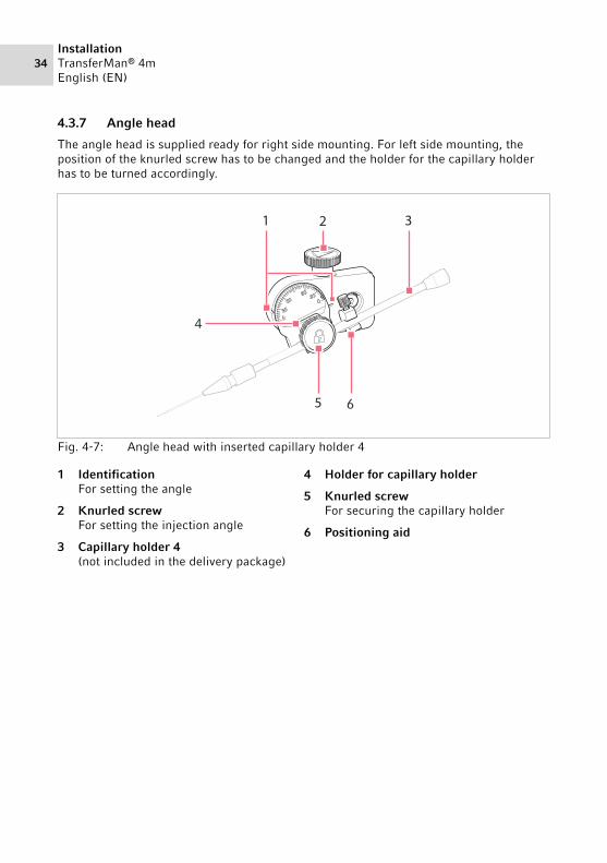
4.3.7 Angle head
The angle head is supplied ready for right side mounting. For left side mounting, the position of the knurled screw has to be changed and the holder for the capillary holder has to be turned accordingly.Abb. 4-7:Angle head with inserted capillary holder 4
Fig. 4-7: Angle head with inserted capillary holder 4
1 IdentificationFor setting the angle
2 Knurled screwFor setting the injection angle
3 Capillary holder 4(not included in the delivery package)
4 Holder for capillary holder
5 Knurled screwFor securing the capillary holder
6 Positioning aid
2 31
5 6
4

InstallationTransferMan® 4m
English (EN)35
4.3.8 Swivel joint
The swivel is supplied ready for right side mounting. For mounting on the left-hand side, the swivel joint must be modified.Abb. 4-8:Swivel joint for right side mounting of the motor module
Fig. 4-8: Swivel joint for right side mounting of the motor module
4.4 Mounting the motor module
The motor module can be mounted on the right-hand or left-hand side of the microscope adapter. The following describes mounting on the right-hand side. For mounting on the left-hand side, the swivel joint and the angle head must be modified.
1 SliderY-module
2 Turntable
3 Allen screws
4 SliderX-module
5 Stop plate
6 Upper joint
7 Mounting mark| stands for left side mounting|| stands for right side mounting
8 Lower joint
The motor module is mounted as standard on an inverse microscope. It can also be mounted on a universal stand. Mounting on a universal stand is described in the corresponding manual.
5
67
8
2
3
4
1

36InstallationTransferMan® 4mEnglish (EN)
4.4.1 Mounting the Z-module – horizontal microscope adapter
Prerequisites• Horizontally mounted microscope adapter• Installation manual for the microscope adapter• Allen torque screwdriver, 3 mm
1. Slide the Z-module holder onto the microscope adapter.
2. Push the fixed rail onto the Z-module holder until it reaches the stop angle and tighten the screw.The connecting cable must point to the rear.
3. Take the setting position for the Z-module holder from table column 1 (installation manual for the microscope adapter).
4. Slide the Z-module holder with the Z-module into its setting position and tighten the screw.

InstallationTransferMan® 4m
English (EN)37
4.4.2 Mounting the Z-module – vertical microscope adapter
Prerequisites• Vertically mounted microscope adapter• Installation manual for the microscope adapter• Allen torque screwdriver, 3 mm
4.4.3 Mounting the Y-module
Prerequisites• Installation manual for the microscope adapter• Allen torque screwdriver, 3 mm
1. Slide the Z-module onto the Z-slider and tighten the screw slightly.
2. Take the setting position for the Z-module from table column 1 (installation manual for the microscope adapter).
3. Slide the Z-module into its setting position and tighten the screw.
1. Undo the screw on the YZ connector.2. Take the setting position from table
column 3 (installation manual for the microscope adapter).
3. Set the position on the front edge of the YZ connector.
4. Tighten the screw on the YZ connector.
38InstallationTransferMan® 4mEnglish (EN)
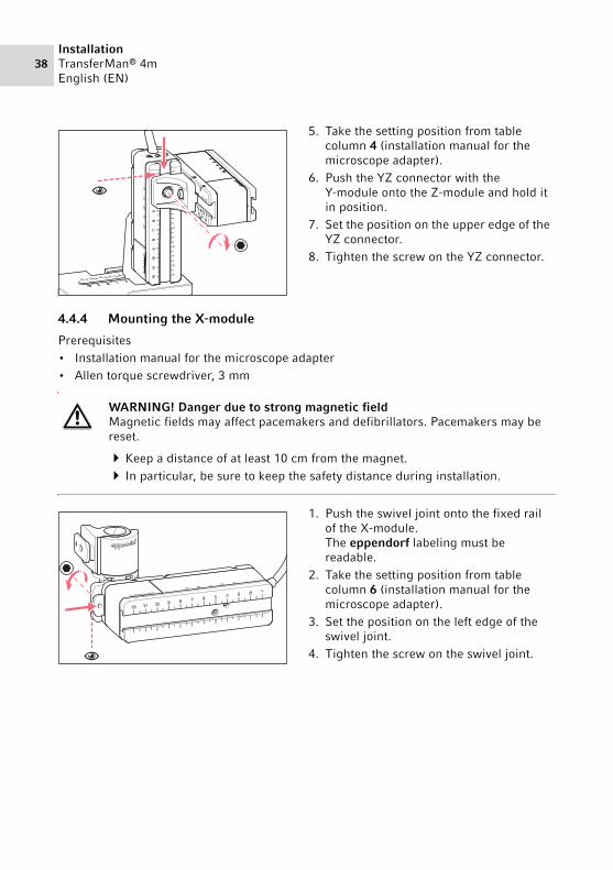
4.4.4 Mounting the X-module
Prerequisites• Installation manual for the microscope adapter• Allen torque screwdriver, 3 mm
5. Take the setting position from table column 4 (installation manual for the microscope adapter).
6. Push the YZ connector with the Y-module onto the Z-module and hold it in position.
7. Set the position on the upper edge of the YZ connector.
8. Tighten the screw on the YZ connector.
WARNING! Danger due to strong magnetic fieldMagnetic fields may affect pacemakers and defibrillators. Pacemakers may be reset.
Keep a distance of at least 10 cm from the magnet. In particular, be sure to keep the safety distance during installation.
1. Push the swivel joint onto the fixed rail of the X-module.The eppendorf labeling must be readable.
2. Take the setting position from table column 6 (installation manual for the microscope adapter).
3. Set the position on the left edge of the swivel joint.
4. Tighten the screw on the swivel joint.
InstallationTransferMan® 4m
English (EN)39
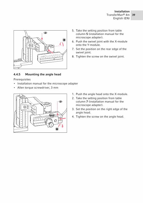
4.4.5 Mounting the angle head
Prerequisites• Installation manual for the microscope adapter• Allen torque screwdriver, 3 mm
5. Take the setting position from table column 5 (installation manual for the microscope adapter).
6. Push the swivel joint with the X-module onto the Y-module.
7. Set the position on the rear edge of the swivel joint.
8. Tighten the screw on the swivel joint.
1. Push the angle head onto the X-module.2. Take the setting position from table
column 7 (installation manual for the microscope adapter).
3. Set the position on the right edge of the angle head.
4. Tighten the screw on the angle head.

40InstallationTransferMan® 4mEnglish (EN)
4.5 Inserting o-rings in the grip headAbb. 4-9:Cross-section of the grip head with correctly inserted o-rings and distancing sleeve
Fig. 4-9: Cross-section of the grip head with correctly inserted o-rings and distancing sleeve
Prerequisites• The o-rings and the distancing sleeve are clean and free of damage.• The grip head is clean and free of damage.• A flat and clean surface is available.
1. Place the o-rings and the distancing sleeve on a flat surface.
2. Press the grip head vertically onto the first o-ring and push it into the grip head with the capillary holder.
3. Press the grip head vertically onto the distancing sleeve and push it into the grip head with the capillary holder.
4. Press the grip head vertically onto the second o-ring and push it into the grip head with the capillary holder.

InstallationTransferMan® 4m
English (EN)41
4.6 Inserting the capillary holder into the angle head
Prerequisites• Capillary holder 4 from Eppendorf is prepared.• Capillary holder (diameter: 4 mm) from another manufacturer is prepared.• The O-rings are inserted in the grip head.
4.6.1 Attaching the positioning aid
Prerequisites• The positioning aid is prepared.• The capillary holder is inserted in the angle head.
The positioning aid can be attached to the capillary holder to quickly clamp it in the same position.
1. Loosen the knurled screw on the angle head.
2. Insert the capillary holder into the clamp.
3. Align the capillary holder in such a way that the capillary tip is located approx. 20 mm above and approx. 20 mm from the outside of the operating point.
1. Place the positioning aid on the capillary holder and tighten.
2. Tighten the knurled screw.

42InstallationTransferMan® 4mEnglish (EN)
4.7 Inserting the capillary
Prerequisites• The O-rings are inserted in the grip head.
WARNING! Risk of injury due to flying capillaries and glass splinters.If exposed to high pressures, capillaries may detach themselves from the grip heads and become projectiles.Capillaries can crack as a result of incorrect handling.
Wear protective goggles.Never aim capillaries at people.Use capillaries with an outer diameter that matches the grip head
specifications.Always mount / dismount capillaries when they are depressurized.Mount the capillary correctly in the grip head.Do not touch the capillary with the Petri dish or other objects.
NOTICE! Mechanical damage to the motor modules.Excessive load leads to increment errors or destruction of the drive.
Do not drive the modules against mechanical obstructions.Do not hold any objects near the modules.Load the motor module with a maximum of 200 g.
Standard capillary: Only use the grip head 4, size 0, with capillaries with an outer diameter of 1.0 mm to 1.1 mm. If you would like to use other capillaries, order the matching gear head.
1. Push the capillary into the grip head until it reaches the stop and tighten the grip head.
InstallationTransferMan® 4m
English (EN)43
4.8 Inserting Femtotips
Prerequisites• Capillary holder 4 is prepared.• Adapter for Femtotips is prepared.
1. Remove the grip head.2. Screw the adapter for Femtotips into the capillary holder.3. Screw the Femtotip into the adapter and tighten.
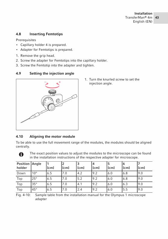
4.9 Setting the injection angle
4.10 Aligning the motor module
To be able to use the full movement range of the modules, the modules should be aligned centrally.
Abb. 4-10:Sample table from the installation manual for the Olympus 1 microscope adapter
Fig. 4-10: Sample table from the installation manual for the Olympus 1 microscope adapter
1. Turn the knurled screw to set the injection angle.
The exact position values to adjust the modules to the microscope can be found in the installation instructions of the respective adapter for microscope.
+
Position holder
Angle 1[cm]
2[cm]
3[cm]
4[cm]
5[cm]
6[cm]
7[cm]
Down 10° 6.5 7.0 4.2 9.2 6.0 6.8 9.0
Top 25° 6.5 7.0 5.2 9.2 6.0 6.8 9.0
Top 35° 6.5 7.0 4.1 9.2 6.0 6.3 9.0
Top 45° 6.5 7.0 2.4 9.2 6.0 5.5 9.0

44InstallationTransferMan® 4mEnglish (EN)
4.10.1 Aligning the height
4.10.2 Aligning the depth
4.10.3 Aligning the width
1. Undo the screw on the YZ connector. 2. Align the Y-module on the scale of the
Z-module.3. Tighten the screw to the set torque.
1. Undo the screw on the swivel joint. 2. Align the X-module on the scale of the
Y-module.3. Tighten the screw to the set torque.
1. Undo the screw on the Z-module holder. 2. Align the Z-module on the scale of the
microscope adapter.3. Tighten the screw to the set torque.

InstallationTransferMan® 4m
English (EN)45
4.10.4 Aligning the angle head
4.11 Entering mounting parameters
To facilitate easy remounting, the mounting parameters can be recorded.
Enter the mounting parameters in the tables.
4.11.1 Microscope and adapter
1. Undo the screw on the angle head. 2. Align the angle head on the scale of the
X-module.3. Tighten the screw to the set torque.
Name Type
Microscope
Adapter
Attachment side of the motor module
46InstallationTransferMan® 4mEnglish (EN)
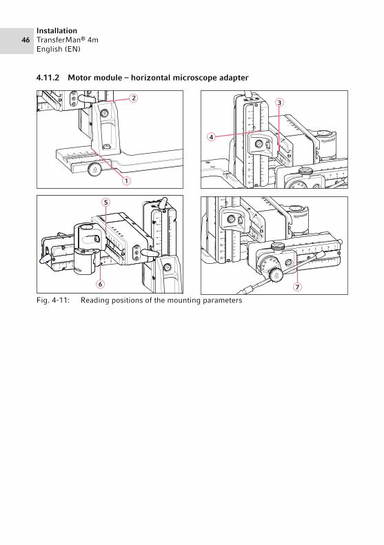
4.11.2 Motor module – horizontal microscope adapter Abb. 4-11:Reading positions of the mounting parameters
Fig. 4-11: Reading positions of the mounting parameters
3
4
5
6 7
2
1

InstallationTransferMan® 4m
English (EN)47
4.11.3 Motor module – vertical microscope adapter Abb. 4-12:Reading positions of the mounting parameters
Fig. 4-12: Reading positions of the mounting parameters
4.11.4 Angle head
Reading position Position [cm]
1
2
3
4
5
6
7
Name Position [cm] Degrees
Capillary holder
Injection angle
2
4
1
6
3
5 7

48InstallationTransferMan® 4mEnglish (EN)
4.12 Converting the swivel joint for left side mounting
Prerequisites• 2 mm Allen key• Right side mounting marks (||) are aligned above each other
WARNING! Danger due to strong magnetic fieldMagnetic fields may affect pacemakers and defibrillators. Pacemakers may be reset.
Keep a distance of at least 10 cm from the magnet. In particular, be sure to keep the safety distance during installation.
1. Rotate the lower joint until both Allen screws are accessible.
2. Unscrew the Allen screws.

InstallationTransferMan® 4m
English (EN)49
3. Open the upper joint a little bit.The magnets are not in contact with the stop plate.The stop plate can be removed more easily.
4. Remove the stop plate.
5. Rotate the lower joint back.6. Rotate the upper joint by 180°.
The sliders must be at a 90° angle to each other.
50InstallationTransferMan® 4mEnglish (EN)
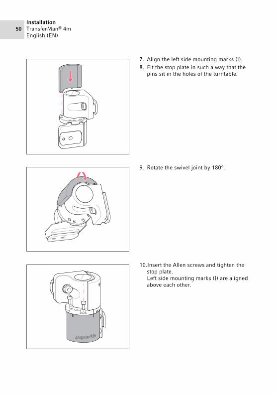
7. Align the left side mounting marks (I).8. Fit the stop plate in such a way that the
pins sit in the holes of the turntable.
9. Rotate the swivel joint by 180°.
10.Insert the Allen screws and tighten the stop plate.Left side mounting marks (|) are aligned above each other.

InstallationTransferMan® 4m
English (EN)51
4.13 Converting the angle head for left side mounting
Prerequisites• 1.3 mm Allen key.
11.Check the position of the joints.The sliders must be at a 90° angle to each other.The eppendorf labeling must be readable.
1. Undo the set screw and pull the knurled screw off the spindle.
90°

52InstallationTransferMan® 4mEnglish (EN)
4.14 Connect the motor module to the control board
2. Rotate the angle head by 180°.3. Push the knurled screw onto the spindle
end and fasten it with the set screw.
4. Turn the knurled screw until the desired angle is set.
WARNING! Danger due to incorrect voltage supply.
Only connect the device to voltage sources which correspond with the electrical requirements on the name plate.
Only use earth/grounded sockets with a protective earth (PE) conductor.Use the supplied mains/power cord only.
NOTICE! Damage to the control board as a result of incorrect handling.
Grasp the control board on the housing.Do not lift the control board using the joystick.Never place the control board on the joystick.
+
InstallationTransferMan® 4m
English (EN)53
Prerequisites• TransferMan 4m is switched off.• The power cable is disconnected.
1. Connect the module (X,Y,Z) plug with the ports on the control board.2. Tighten the fixing screws on the plug manually.3. Connect the mains/power cord.4. Switch on the mains switch.5. Set the installation parameters. You can use the software wizard First set-up or the
Installation menu to set the Side and Angle parameters.
4.15 Setting installation parameters
Installation parameters must be set: • During first set-up• After a reset
The following settings are defined:• Mounting side of the motor module• Center motors• Adjust motors• Set date• Dynamic movement range of the joystick
NOTICE! Material damage from incorrect connections.
Only electrical connections may be made to devices described in the operating manual.
Other connections are permitted only with the agreement of Eppendorf AG.Only connect devices that meet the safety requirements defined in IEC
60950-1.
NOTICE! Short circuit caused by incorrect installation.
Failure to observe the order of steps may result in a short circuit.

54InstallationTransferMan® 4mEnglish (EN)
4.15.1 First set-up wizard
Prerequisites• The micromanipulator is switched on.• The capillary holder is not installed.
1. Select the First set-up application.
2. Select the mounting side.3. Select Next.
4. Select Next.

InstallationTransferMan® 4m
English (EN)55
5. Select Execute.The X-motor and the Y-motor are moved to the middle position.The Z-motor is set to a 20/80 position.
6. Select Next.
7. Insert the capillary holder into the angle head.
8. Select Next.
9. Align the modules manually with an Allen key.
10.Select Next.
11.Remove the capillary holder.12.Insert the capillary into the capillary
holder.13.Insert the capillary holder with the
capillary into the angle head.14.Finely adjust the position of the capillary
holder and the modules. Align the capillary tip so that it is approximately in the focus of the microscope.
15.Select Next.
56InstallationTransferMan® 4mEnglish (EN)
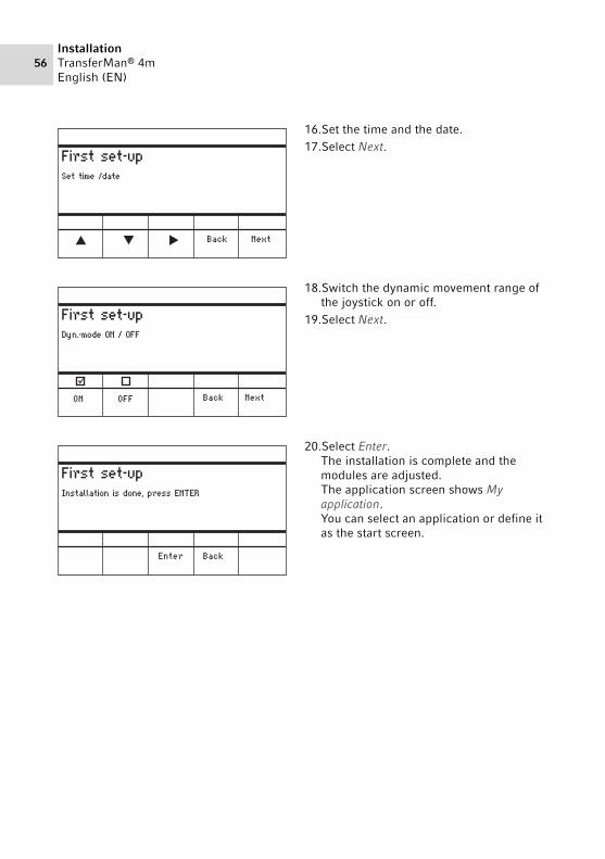
16.Set the time and the date.17.Select Next.
18.Switch the dynamic movement range of the joystick on or off.
19.Select Next.
20.Select Enter.The installation is complete and the modules are adjusted.The application screen shows My application.You can select an application or define it as the start screen.

SoftwareTransferMan® 4m
English (EN)57
5 Software5.1 Display
The display shows current settings, e.g., the selected working range, the position of the motors and the defined limits.
5.1.1 Application displayAbb. 5-1:Display layout - ICSI application example
Fig. 5-1: Display layout - ICSI application example
1 Status line with working range
2 Active application with speed bars
3 Connected device
4 Softkey status fields
5 Softkeys
6 Function of the joystick key
7 Display of coordinates
8 Display of defined limits
1
2
3
5
4
6
7
8
58SoftwareTransferMan® 4mEnglish (EN)
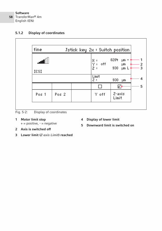
5.1.2 Display of coordinatesAbb. 5-2:Display of coordinates
Fig. 5-2: Display of coordinates
1 Motor limit stop+ = positive, - = negative
2 Axis is switched off
3 Lower limit (Z-axis Limit) reached
4 Display of lower limit
5 Downward limit is switched on
12
4
3
5

SoftwareTransferMan® 4m
English (EN)59
5.1.3 Menu displayAbb. 5-3:Menu and parameter display
Fig. 5-3: Menu and parameter display
1 Navigation path
2 Menu
3 Arrow up/down softkeyNavigation and changing parameters.
4 Enter softkeyFor confirming input, executing the function, saving parameters
5 Arrow left/right softkeyNavigation
6 Parameter
3
4
5
6
1
2

60SoftwareTransferMan® 4mEnglish (EN)
5.2 ApplicationsAbb. 5-4:Application screen
Fig. 5-4: Application screen
Application selection• Select an application• Store the main application
5.2.1 Application parameters
Predefined softkeys of the different applications.
Application parameter Description
Pos 1 Save the X, Y and Z values of the capillary position. Switch the position using the joystick key.
Pos 2 Save the X, Y and Z values of the capillary position. Switch the position using the joystick key.
Pos 3 Save the X, Y and Z values of the capillary position. Switch the position using the joystick key.
Y off Switch off the movement of the capillary in the Y-axis. Prevents moving sideways during injection.
Z-axis Limit Set the lower limit for vertical capillary movement.
Axial Switch on the capillary movement along the mounting bracket.
SoftwareTransferMan® 4m
English (EN)61
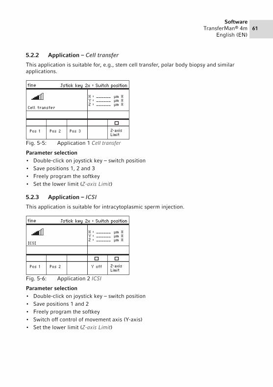
5.2.2 Application – Cell transfer
This application is suitable for, e.g., stem cell transfer, polar body biopsy and similar applications.Abb. 5-5:Application 1 Cell transfer
Fig. 5-5: Application 1 Cell transfer
Parameter selection• Double-click on joystick key – switch position• Save positions 1, 2 and 3• Freely program the softkey• Set the lower limit (Z-axis Limit)
5.2.3 Application – ICSI
This application is suitable for intracytoplasmic sperm injection.Abb. 5-6:Application 2 ICSI
Fig. 5-6: Application 2 ICSI
Parameter selection• Double-click on joystick key – switch position• Save positions 1 and 2• Freely program the softkey• Switch off control of movement axis (Y-axis)• Set the lower limit (Z-axis Limit)

62SoftwareTransferMan® 4mEnglish (EN)
5.2.4 Application – DNA injection
This application is suitable for injection movements along the horizontal plane (e.g., pronucleus injection).Abb. 5-7:Application 3 DNA injection
Fig. 5-7: Application 3 DNA injection
Parameter selection• Double-click on joystick key – switch position• Save positions 1 and 2• Freely program the softkey• Switch off control of movement axis (Y-axis)• Set the lower limit (Z-axis Limit)
5.2.5 Application – Basic
This application is suitable for injection movements into larger organisms (e.g., Drosophila embryos).Abb. 5-8:Application 4 Basic
Fig. 5-8: Application 4 Basic
Parameter selection• Double-click on joystick key – switch position• Save position 1• Freely program the softkey• Switch on the axial movement of the Z-axis• Freely program the softkey• Set the lower limit (Z-axis Limit)
SoftwareTransferMan® 4m
English (EN)63
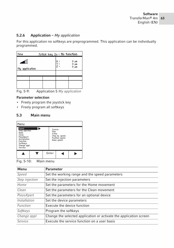
5.2.6 Application – My application
For this application no softkeys are preprogrammed. This application can be individually programmed.Abb. 5-9:Application 5 My application
Fig. 5-9: Application 5 My application
Parameter selection• Freely program the joystick key• Freely program all softkeys
5.3 Main menuAbb. 5-10:Main menu
Fig. 5-10: Main menu
Menu ParameterSpeed Set the working range and the speed parameters
Step injection Set the injection parameters
Home Set the parameters for the Home movement
Clean Set the parameters for the Clean movement
PiezoXpert Set the parameters for an optional device
Installation Set the device parameters
Function Execute the device function
Softkeys Program the softkeys
Change appl Change the selected application or activate the application screen
Service Execute the service function on a user basis

64SoftwareTransferMan® 4mEnglish (EN)
5.4 Navigating the menuAbb. 5-11:Software navigation
Fig. 5-11: Software navigation
Navigate the menu using the arrow keys. Pressing Enter will confirm the selection. You can switch between menus and submenus with the arrow keys to the left and to the right.
5.4.1 Entering or changing parameters
Parameters can be changed in the menu using the arrow keys, the selection dial or the rotating wheel on the joystick.
Abb. 5-12:Changing the parameters
Fig. 5-12: Changing the parameters
Change values with the upwards or downwards arrow keys.
Change values using the selection dial.Change values using the upper part of
the joystick.Save with Enter.

OperationTransferMan® 4m
English (EN)65
6 Operation
6.1 Switching the device on or off6.1.1 Switching the device on
1. Switch on the device at the mains/power switch.The motor module and the control board are switched on.The device runs through an initialization phase.The application screen appears.
6.1.2 Switching off the device
1. Switch off the device at the mains/power switch.The motor module and the control board are deenergized.
6.2 Activating or deactivating the control board6.2.1 Activating the control board
Prerequisites• The display shows STANDBY.
1. Press the standby key.The keys, joystick, selection dial, and softkeys are activated.The display shows the application screen.
6.2.2 Deactivating the control board
The step motors slowly move to the next parking position. This prevents the motors falling back to the parking position and the capillary jumping.
1. Press the standby key.The keys, joystick, and selection dial are deactivated.The display shows STANDBY.Current movements are stopped.The motor module remains switched on so that the step motors keep their current position.
WARNING! Electric shock due to damage to device or mains/power cord.
Only switch on the device if the device and the mains/power cord are undamaged.
Only operate devices which have been installed or repaired properly. In case of danger, disconnect the device from the mains/power supply
voltage. Disconnect the mains/power plug from the device or the earth/grounded socket. Use the isolating device intended for this purpose (e.g., the emergency switch in the laboratory).
Do not move the joystick immediately after power-on. Wait until the initialization is completed. The completion of initialization is indicated by the display switching to the operating state.

66OperationTransferMan® 4mEnglish (EN)
6.3 Defining the start screen
An application can be selected as the default application. The micromanipulator then starts with the defined application. The application screen with all the applications can be redefined in the Start display menu.
6.3.1 Defining the application
1. Press and hold the softkey of the desired application for 3 seconds.The micromanipulator always starts with the defined application.
6.3.2 Defining the selected application
1. In the Change appl menu, select the Start display submenu.2. Select Execute.3. Confirm with Enter.
The micromanipulator starts with the selected application.
6.4 Replacing the capillary
Prerequisites• The capillary is depressurized.
WARNING! Risk of injury due to flying capillaries and glass splinters.If exposed to high pressures, capillaries may detach themselves from the grip heads and become projectiles.Capillaries can crack as a result of incorrect handling.
Wear protective goggles.Never aim capillaries at people.Use capillaries with an outer diameter that matches the grip head
specifications.Always mount / dismount capillaries when they are depressurized.Mount the capillary correctly in the grip head.Do not touch the capillary with the Petri dish or other objects.
CAUTION! Risk of injury from capillariesCapillaries can easily penetrate your skin.
After changing a capillary, swivel it immediately back to the working range.
CAUTION! Risk of crushing between the modulesThe modules automatically move in all spatial axes.
Do not reach into the movement range of the modules.

OperationTransferMan® 4m
English (EN)67
6.4.1 Manually positioning the capillary
1. Press the Back manual key.2. Manually position the capillary in the working range.
6.4.2 Automatically positioning the capillary
1. Press the home key.The capillary automatically moves back into the working range.
1. Move the capillary out of the working range using the home key.
2. Swing the X-module forwards.3. Undo the grip head on the capillary
holder.4. Carefully pull the capillary out of the grip
head.5. Push the new capillary into the grip head
until it reaches the stop and tighten the grip head.
6. Swing the X-module back.
Suitable when using capillaries of different lengths (e.g., self-pulled capillary).
Suitable for industrial capillaries of exactly the same length.

68OperationTransferMan® 4mEnglish (EN)
6.5 Changing the sample
6.6 Changing the size of the working range 6.6.1 Change parameters using the selection dial
CAUTION! Risk of crushing between the modulesThe modules automatically move in all spatial axes.
Do not reach into the movement range of the modules.
1. Press the home key to move the capillary out of the working range.
2. Swing the X-module backwards.3. Change the sample.4. Swing the X-module back.5. Press the home key to move the capillary
back into the working range.
1. Press the key for the required working range on the control panel.
2. Turn the selection dial to change the value of the working range.
menu
finefine
coarse

OperationTransferMan® 4m
English (EN)69
6.6.2 Changing parameters in the menu
Prerequisites• An application has been selected.
6.7 Shifting the movement range of the capillary6.7.1 Extending the movement range into the dynamic range
When the movement range of the capillary is not sufficient, the joystick can be moved into the dynamic range. By doing that you can move the capillary further into the required direction.
1. Move the joystick into the dynamic range.2. Keep the joystick in the dynamic range until the capillary has reached the desired
position.The further you move the joystick forwards or backwards, the faster the capillary will move.
6.7.2 Uncoupling and resetting the joystick
When the current movement range of the capillary is not in the correct position, the joystick movement can be uncoupled from the capillary movement. By doing that you can reset the joystick and move the capillary further into the required direction.
1. Press the menu key.2. Select theSpeed menu.3. Select the desired parameter.4. Change the value.
1. Hold the joystick button.2. Move the joystick in the opposite
direction.3. Release the joystick.
The capillary can now be moved further into the required direction.
70OperationTransferMan® 4mEnglish (EN)
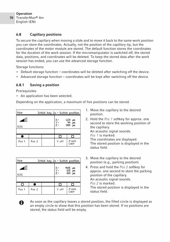
6.8 Capillary positions
To secure the capillary when moving a slide and to move it back to the same work position you can store the coordinates. Actually, not the position of the capillary tip, but the coordinates of the motor module are stored. The default function stores the coordinates for the duration of the work session. If the micromanipulator is switched off, the stored data, positions, and coordinates will be deleted. To keep the stored data after the work session has ended, you can use the advanced storage function.
Storage functions:• Default storage function – coordinates will be deleted after switching off the device.• Advanced storage function – coordinates will be kept after switching off the device.
6.8.1 Saving a position
Prerequisites• An application has been selected.
Depending on the application, a maximum of five positions can be stored.
1. Move the capillary to the desired position.
2. Hold the Pos 1 softkey for approx. one second to store the working position of the capillary.An acoustic signal sounds.Pos 1 is marked.The coordinates are displayed. The stored position is displayed in the status field.
3. Move the capillary to the desired position (e.g., parking position).
4. Press and hold the Pos 2 softkey for approx. one second to store the parking position of the capillary.An acoustic signal sounds.Pos 2 is marked.The stored position is displayed in the status field.
As soon as the capillary leaves a stored position, the filled circle is displayed as an empty circle to show that this position has been stored. If no positions are stored, the status field will be empty.

OperationTransferMan® 4m
English (EN)71
6.8.2 Moving to the position using the softkey
Prerequisites• At least one position is stored.
1. Press a softkey with a stored position.You will move to the selected position.The joystick is deactivated until the position has been reached.The LEDs flash.In the softkey status field a filled circle is displayed.
6.8.3 Moving to the position using the joystick key
Prerequisites• At least one position is stored.• The Joystick key parameter must be set to the Switch position value.
6.8.4 Overwriting a stored position
Prerequisites• A position is stored.
1. Press the softkey for a different position.You will move to the position.
2. When the position has been reached, press and hold the softkey for the position to be overwritten.The old position is overwritten with the current coordinates.
3. Press the softkey.An acoustic signal sounds.In the softkey status field a filled circle is displayed.The stored position is displayed in the coordinate field.
If a stored position is lower than the lower limit (Z-axis Limit), the position on the Z-axis will only be approached up to the defined limit.
Press the joystick key twice.You will move to the first position.
Press the joystick key twice.You will move to the next position.

72OperationTransferMan® 4mEnglish (EN)
6.8.5 Deleting a stored position
Prerequisites• A position is stored.
1. When the position has been reached, hold the softkey.An acoustic signal sounds.The position has been deleted.The status field is empty.
6.9 Using the advanced storage function
The following data is stored:• the current coordinates of the motor module.• the data of the Pos 1 to Pos 5 softkeys. • the defined vertical (Z-axis Limit and Upper limit) or horizontal (X-axis Limit) limits.
Prerequisites• An application has been defined as the default application.• At least one position or limit has been defined.
1. Press the standby key.The specified data of the work session will be stored.The current coordinates of the motor module will be stored.For technical reasons, the motors will still move a few micrometers after this to get into a defined end position.The micromanipulator can be switched off at the mains/power switch. The data will be available when the micromanipulator is started the next time.
6.10 Vertical limits
For the Z-axis, a lower and upper limit can be defined. This prevents the capillary coming into contact with the bottom of the Petri dish or moving against the condenser of the microscope adapter.
• Lower limit – Z-axis Limit• Upper limit – Upper limit

OperationTransferMan® 4m
English (EN)73
6.10.1 Defining the lower limit
Prerequisites• An application has been selected.
6.10.2 Deleting the lower limit
6.10.3 Defining the upper limit
6.10.4 Deleting the upper limit
1. In the Installation menu, select the Upper limit submenu.The Upper Limit window appears.
2. Save the position with Clear.The limit is deleted.
1. Position the capillary a little way above the slide.
2. Press Z-axis Limit.The Z-coordinate is marked with L.The value for the limit (Limit Z) is displayed.Z-axis Limit is selected.The capillary cannot be moved any lower.
1. Press Z-axis Limit.The limit is deleted.
1. In the Installation menu, select the Upper limit submenu.The Upper Limit window appears.
2. Move the capillary to the top position.3. Save the position with Set.
The Z-coordinate is marked with U.The value for the limit (Lim) is displayed.The capillary cannot be moved any higher.
Upper Limit
Menu / Installation / Upper Limit
BackSetClear
XYZ
Lim
===
00
2671
2671
µmµmµm U
µm

74OperationTransferMan® 4mEnglish (EN)
6.11 Horizontal limit
For the X-axis, a limit can be defined for a horizontal injection. This prevents the capillary from moving through the sample.
6.11.1 Defining the horizontal limit
1. In the Installation menu, select the Angle submenu.2. Set the injection angle to 0° and save with Enter.3. Close the menu.
The application screen now displays X-axis Limit.
4. Move the capillary to the desired final position for the X-axis.5. Save the lateral limit with X-axis Limit.
The X-coordinate is marked with L.The value for the limit (Limit X) is displayed.X-axis Limit is selected.The capillary cannot be moved any further to the side.
6.11.2 Deleting the horizontal limit
1. Press X-axis Limit.The limit is deactivated.
2. In the Installation menu, select the Angle submenu.3. Reset the injection angle to the operating angle and save with Enter.
The lateral limit is deleted.The application screen displays Back again.

OperationTransferMan® 4m
English (EN)75
6.12 Speed function
In the Speed menu you can set the size of the working range and the speed at which certain positions are approached or movements executed.
6.12.1 Speed menu and parametersAbb. 6-1:Menu – Speed
Fig. 6-1: Menu – Speed
6.12.2 Setting the parameter for Speed
1. Select the desired parameter.2. Set the value for the parameter.3. Close the menu.
Parameter Value Range of values
Increment Standard
Coarse Set size in μm 5 – 12500 5 6000
Fine Set size in μm 5 – 2000 5 250
X-fine Set size in μm 0 – 600 1 80
Step inj. speed Set speed in μm per second 5 – 10000 5 300
Position speed Set speed in μm per second 5 – 10000 5 1500
Home speed Set speed in μm per second 5 – 10000 5 7500
If a value of 0 is set for the parameter X-fine, then the option of changing between the Fine and X-fine working ranges is deactivated.

76OperationTransferMan® 4mEnglish (EN)
6.13 Step injection function
With this function you can execute a straight injection over a defined distance. Step injection can be executed with the foot control or with a connected FemtoJet.
6.13.1 Step injection menu and parametersAbb. 6-2:Menu – Step injection
Fig. 6-2: Menu – Step injection
This function is not authorized for medical use.
Parameter Value Range of values
Increment Standard
Step injection Switch the function on or off OFF/ON – OFF
Step inj. speed Set the injection speed in μm per second
5 – 10000 5 300
Step inj. dist Set the injection path in μm 1 – 2000 1 20
Step inj. axial Switch the axial movement of the capillary on or off
OFF/ON – On
Step inj. back Switch the backward movement of the capillary on or off
OFF/ON – On
Synchr. inject Set the time of injection MOVEIMMEDIATELIMITPRESSURE
– LIMIT
Parameter Range of values
Function
Synchr. inject MOVE Injection movement without injection pressure
IMMEDIATE Injection pressure starts with the injection movement
LIMIT Injection pressure at the end of the injection distance (Step inj. dist)
PRESSURE Injection pressure without injection movement

OperationTransferMan® 4m
English (EN)77
6.13.2 Executing the Step injection function
Prerequisites• A FemtoJet is connected.• Step injection is assigned to a free softkey.
1. Activate Step injection.2. Set Step inj. dist.3. Set the injection time on the FemtoJet.4. Select Step inj. dist.5. Close the menu.
The application screen displays Step injection.
6. Trigger the injection by selecting Inject on the FemtoJet.The function is executed.
6.14 Home function
The Home function quickly moves the capillary out of the work area and is suitable for a quick change of capillary.
6.14.1 Home menu and parametersAbb. 6-3:Menu – Home
Fig. 6-3: Menu – Home
Parameter Value Range of values
Increment Standard
Home speed Set the speed of the Home function in μm/s
5 – 10000 5 7500
Home offset Set vertical offset in μm 5 – 20000 5 0

78OperationTransferMan® 4mEnglish (EN)
6.14.2 Setting the parameter for Home
1. Set the speed.2. Set the offset.3. Close the menu.
6.14.3 Move the capillary out with the home key
Prerequisites• The parameters in the Home menu have been defined.
6.14.4 Move the capillary back with the home key
1. Press the home key.The home function is terminated.The capillary is moved back into the work area.
6.14.5 Setting the offset.
For capillaries of different lengths, an offset can be set. This defines a limit for the home function.
CAUTION! Risk of crushing between the modulesThe modules automatically move in all spatial axes.
Do not reach into the movement range of the modules.
1. Press the home key.The home key flashes.The capillary is moved out of the work area.The home key lights up.
CAUTION! Risk of crushing between the modulesThe modules automatically move in all spatial axes.
Do not reach into the movement range of the modules.

OperationTransferMan® 4m
English (EN)79
6.14.6 Terminate the home function.
6.15 Clean function
With this function you can move the capillary over a defined distance out of the medium. In the process, outside contamination is removed from the capillary at the medium boundary.
6.15.1 Clean menu and parametersAbb. 6-4:Menu – Clean
Fig. 6-4: Menu – Clean
1. Change the offset using the arrow keys.The value for the offset is displayed in the status field.
1. Press Back manual.The home function is terminated.
2. Move the capillary manually using the joystick.

80OperationTransferMan® 4mEnglish (EN)
6.15.2 Setting the parameter for Clean
1. Set Home speed.2. Set Clean distance.3. Close the menu.
6.15.3 Execute the Clean function
Prerequisites• Parameters are set for Clean. • Clean is assigned to a softkey.
6.15.4 Terminate the Clean function.
Parameter Value Range of values
Increment Standard
Home speed Set the speed of the Clean function in μm/s
5 – 10000 5 7500
Clean distance Set distance in μm 0 – 20000 5 10000
Set the Clean distance above the medium boundary
1. Press Clean.The screen for Clean appears.
2. Execute the function with Clean.The capillary is moved out of the medium with the set parameters.
1. Press Back manual.The function is terminated.The application screen appears.

OperationTransferMan® 4m
English (EN)81
6.16 PiezoXpert function
6.16.1 PiezoXpert menu and parametersAbb. 6-5:Menu – PiezoXpert
Fig. 6-5: Menu – PiezoXpert
This function is not authorized for medical use.
Parameter Value Range of values
Increment Standard
Synchr. PiezoXp
Switch synchronization between TransferMan 4m and PiezoXpert on or off
OFF/ON – –
PiezoXp. speed
Set the advance rate of the manipulator in μm/s while the PiezoXpert triggers a pulse.
5 – 10000 5 300
PiezoXp. dist Set the length of the movement step of the manipulator in μm while the PiezoXpert triggers a pulse.
1 – 2000 1 20
PiezoXp. axial Axial movement on or off (corresponds to the set injection angle) On = movement in the X and Y-axis Off = movement in the X-axis
ON/OFF – OFF

82OperationTransferMan® 4mEnglish (EN)
6.16.2 Execute the PiezoXpert function
Prerequisites• A PiezoXpert is connected.
1. Activate Synchr. PiezoXp.2. Set PiezoXp. speed.3. Set PiezoXp. dist.4. Select PiezoXp. axial.5. Close the menu.6. Trigger the function with Channel A on the PiezoXpert.
The function is executed.
6.17 Installation function
This function provides settings for the fine adjustment of the motor module and the control board. Parameters in the Installation menu override identical softkey functions.
6.17.1 Installation menu and parametersAbb. 6-6:Installation menu
Fig. 6-6: Installation menu
6.17.2 Installation parameters
Parameter Value Range of values
Increment Standard
Side Set the mounting side LEFT/RIGHT – RIGHT
Angle Set the capillary angle in degrees 0° – 90° 1 –

OperationTransferMan® 4m
English (EN)83
6.17.3 Control board parameters
6.17.4 Joystick parameters
6.17.5 Module parameters
Parameter Value Range of values
Increment Standard
LCD contrast Set the display contrast 65 % – 75 % 1 70 %
LCD light Set the brightness level of the display
0 % – 100 % 1 100 %
Beeper Setting the volume 0 – 100 % 1 50 %
Display coordin
Set the coordinate display OFF/ON – ON
Parameter Value Range of values
Increment Standard
Z Factor Acceleration factor for the Z-axis relative to the X and Y-axis
5 % – 400 % 5 100
Dyn-mode Switch the dynamic movement range on or off
OFF/ON – ON
Dyn-factor Set the dynamic factor 0 % – 1000 % 1 100 %
Parameter Value Range of values
Increment Standard
Invert X-axis Reverse the direction of movement of the motor
OFF/ON – OFF
Invert Y-axis Reverse the direction of movement of the motor
OFF/ON – OFF
Invert Z-axis Reverse the direction of movement of the motor
OFF/ON – OFF
X-axis off Switch the motor of the movement axis on or off
OFF/ON – OFF
Y-axis off Switch the motor of the movement axis on or off
OFF/ON – OFF
Z-axis off Switch the motor of the movement axis on or off
OFF/ON – OFF
Upper limit Define the upper limit Execute – –
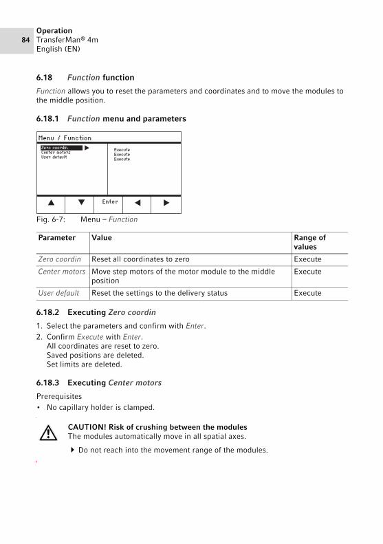
84OperationTransferMan® 4mEnglish (EN)
6.18 Function function
Function allows you to reset the parameters and coordinates and to move the modules to the middle position.
6.18.1 Function menu and parametersAbb. 6-7:Menu – Function
Fig. 6-7: Menu – Function
6.18.2 Executing Zero coordin
1. Select the parameters and confirm with Enter.2. Confirm Execute with Enter.
All coordinates are reset to zero.Saved positions are deleted.Set limits are deleted.
6.18.3 Executing Center motors
Prerequisites• No capillary holder is clamped.
Parameter Value Range of values
Zero coordin Reset all coordinates to zero Execute
Center motors Move step motors of the motor module to the middle position
Execute
User default Reset the settings to the delivery status Execute
CAUTION! Risk of crushing between the modulesThe modules automatically move in all spatial axes.
Do not reach into the movement range of the modules.

OperationTransferMan® 4m
English (EN)85
1. Select the parameters and confirm with Enter.2. Confirm Execute with Enter.
X-motor and Y-motor are moved to the middle position.Z-motor is moved to a 20/80 position.All coordinates are reset to zero.Saved positions are deleted.Set limits are deleted.
6.18.4 Executing User default
1. Select the parameters and confirm with Enter.2. Confirm Execute with Enter.
All parameters are reset to the factory settings.The application screen appears.
6.19 Softkeys function
With this function you can assign programs to free softkeys. Assigned softkeys are indicated with a lock symbol.
6.19.1 Softkeys menu and parametersAbb. 6-8:Menu – Softkeys
Fig. 6-8: Menu – Softkeys
Parameter Value Range of values
Softkey 1 Set the function
Softkey 2 Set the function
Softkey 3 Set the function
Softkey 4 Set the function
Softkey 5 Set the function
Joystick key Set the function for the joystick key No functionSwitch positionSwitch fine

86OperationTransferMan® 4mEnglish (EN)
Parameter Function
No function Softkey has no function
Pos 1 Save, overwrite or delete a position
Pos 2 Save, overwrite or delete a position
Pos 3 Save, overwrite or delete a position
Pos 4 Save, overwrite or delete a position
Pos 5 Save, overwrite or delete a position
Y-axis off Switch the control of the movement axis on or off
Axial Change vertical movement to axial movement
Limit Activate or deactivate the vertical or horizontal (X-axis) limit
Step injection Activate the Step injection function
Limit up Amend value for Z-axis Limit upwards
Limit down Amend value for Z-axis Limit downwards
Clean Axial movement out of the working range
Z-axis only Only control of movements in the Z-axis. The control of movements in the X and Y-axis is disabled
LCD light Set the brightness level of the display
Beeper Set the volume
Joystick off Deactivates all joystick movements
X-axis off Switch the control of the movement axis on or off
Z-axis off Switch the control of the movement axis on or off
X-axis only Only control of movements in the X-axis. The control of movements in the Y and Z-axis is deactivated
Y-axis only Only control of movements in the Y-axis. The control of movements in the X and Z-axis is deactivated
Dyn-mode Activate or deactivate dynamic movement range
Parameter Range of values
Function
Joystick key No function Deactivate the function of the joystick key
Switch position Double-click to go to the next saved position
Switch fine Double-click to go to the fine or x-fine working range

OperationTransferMan® 4m
English (EN)87
6.19.2 Execute Softkeys
1. Select the free softkey and confirm with Enter.2. Select the desired parameter and confirm with Enter.3. Close the menu.
The selected parameter is assigned to the free softkey.The parameter appears on the application screen.
6.19.3 Execute Joystick key
Prerequisites• The My application application has been selected.
1. Select Joystick key and confirm with Enter.2. Select the desired function and confirm with Enter.3. Close the menu.
The function is assigned to the joystick key.The selected function appears on the application screen.
6.20 Change appl function
With this function you can define each application as the start screen or reactivate the default screen.
6.20.1 Change appl menu and parametersAbb. 6-9:Menu – Change appl
Fig. 6-9: Menu – Change appl
Parameter Value Range of values
Start display Reactivate start screen to select an application Execute
Application Define the selected application as the start screen Cell transferICSIDNA injectionBasicMy application

88OperationTransferMan® 4mEnglish (EN)
6.20.2 Defining the application selection as the start screen
1. Select Start display.2. Confirm with Execute.3. Close the menu.
The micromanipulator starts with the selected application.
6.20.3 Defining an application as the start screen
1. Select an application.2. Confirm with Enter.3. Close the menu.
The micromanipulator always starts with the defined application.
6.21 Service function 6.21.1 Service menu and parametersAbb. 6-10:Service menu
Fig. 6-10: Service menu
Parameter Value Range of values
Selftest Move the motor module in all three axes and output error message
EXECUTE
Device info Display the software version EXECUTE
Set clock Set date and time YYYY-MM-DD 00:00
Movements Show movement routes of the modules (X, Y, Z) EXECUTE
Show errors Display the last 10 error messages EXECUTE
Demo run Save the position and move to it EXECUTE

OperationTransferMan® 4m
English (EN)89
6.21.2 Executing the Selftest function
1. Select Selftest and confirm with Enter.2. Confirm Execute with Enter.
The screen for the Selftest function appears.
3. Execute Selftest with Start.The motors move up to the limit stops.
4. Terminate Selftest with Stop.
6.22 Resetting parameters to the factory settings 6.22.1 Perform reset
Reset all parameters to the factory settings.
1. Keep the home key pressed.2. Switch on the device at the mains power switch.
The screen for GENERAL RESET appears.
3. Execute the function with Yes.All parameters are now reset to the factory settings.
6.22.2 Carrying out a reset in the menu
Prerequisites• An application has been selected.
1. Press the menu key.2. Select the Function menu.3. Press Enter.4. Select User default and confirm with Execute.
All parameters are now reset to the factory settings.
CAUTION! Risk of crushing between the modulesThe modules automatically move in all spatial axes.
Do not reach into the movement range of the modules.
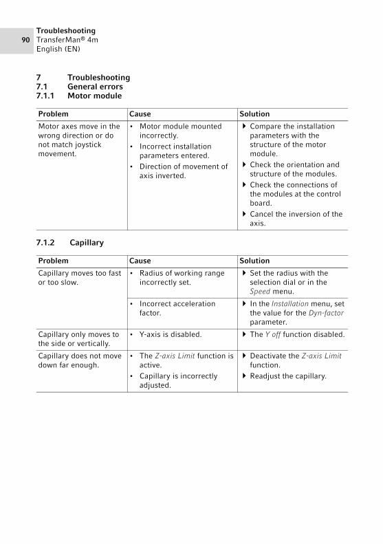
90TroubleshootingTransferMan® 4mEnglish (EN)
7 Troubleshooting7.1 General errors7.1.1 Motor module
7.1.2 Capillary
Problem Cause Solution
Motor axes move in the wrong direction or do not match joystick movement.
• Motor module mounted incorrectly.
• Incorrect installation parameters entered.
• Direction of movement of axis inverted.
Compare the installation parameters with the structure of the motor module.
Check the orientation and structure of the modules.
Check the connections of the modules at the control board.
Cancel the inversion of the axis.
Problem Cause Solution
Capillary moves too fast or too slow.
• Radius of working range incorrectly set.
Set the radius with the selection dial or in the Speed menu.
• Incorrect acceleration factor.
In the Installation menu, set the value for the Dyn-factor parameter.
Capillary only moves to the side or vertically.
• Y-axis is disabled. The Y off function disabled.
Capillary does not move down far enough.
• The Z-axis Limit function is active.
• Capillary is incorrectly adjusted.
Deactivate the Z-axis Limit function.
Readjust the capillary.

TroubleshootingTransferMan® 4m
English (EN)91
7.1.3 Control board and display
7.1.4 Joystick
7.1.5 Software and parameters
Problem Cause Solution
Device does not respond to keystroke when Home function is active.
• function is active. Press the home key again. The capillary moves down.
Press the Back manual softkey.
Move the joystick.
The display does not show anything or the device cannot be activated although the device is connected.
• The power cable or power plug is loose.
• The device is switched off.
Check the power cable or the power plug.
Switch on the device.
Problem Cause Solution
Outer movement range of the joystick does not work.
• Outer movement range is deactivated.
In the Installation menu, set the value for Dyn-mode to ON.
Problem Cause Solution
Parameters are not accessible for certain operations.
– Enter parameters again.Carry out a reset and reset
all parameters to the works settings.
Readjust device.

92TroubleshootingTransferMan® 4mEnglish (EN)
7.2 Error messages7.2.1 Warnings
7.2.2 Error
Problem Cause Solution
WARNING 1 • FemtoJet is not connected. Disconnect the data cable to the FemtoJet and connect it again.
Switch on the FemtoJet.
WARNING 3 • X-module is not connected. Switch off the device.Connect the plug of the
X-module to the control board and tighten.
Switch on the device.
WARNING 4 • Y-module is not connected. Switch off the device.Connect the plug of the
Y-module to the control board and tighten.
Switch on the device.
WARNING 5 • Z-module is not connected. Switch off the device.Connect the plug of the
Z-module to the control board and tighten.
Switch on the device.
WARNING 6 • Synchronization error with FemtoJet during an injection.
Set another synchronization for Synchr. inject.
Set the synchronization IMMEDIATE, LIMIT or PRESSURE.
Problem Cause Solution
ERROR 10 – ERROR 99 • Technical error. Switch the device off and back on.
Reset the parameters to the factory settings.
Contact Eppendorf Service.

MaintenanceTransferMan® 4m
English (EN)93
8 Maintenance8.1 Replacing fuses
The fuse holder is located between the mains connection socket and the mains power switch. The fuses may only be replaced with the same type of fuse.
1. Disconnect the mains plug.2. Pull the fuse holder out completely.3. Replace the defective fuse. 4. Insert the fuse holder.
8.2 Cleaning
1. Wipe all surfaces with a cloth and mild detergent.2. Wipe the painted parts and the aluminum surfaces with a cloth and mild detergent.3. Polish with a dry cloth.
DANGER! Electric shock.
Switch off the device and disconnect the power plug before starting maintenance or cleaning work.
DANGER! Electric shock due to the ingress of liquid.
Switch off the device and disconnect it from the mains/power line before starting cleaning or disinfection.
Do not allow any liquids to penetrate the inside of the housing.Do not spray clean/spray disinfect the housing.Only plug the device back in once it is completely dry, both inside and
outside.
NOTICE! Damage from the use of aggressive chemicals.
Do not use any aggressive chemicals on the device or its accessories, such as strong and weak bases, strong acids, acetone, formaldehyde, halogenated hydrocarbons or phenol.
If the device has been contaminated by aggressive chemicals, clean it immediately using a mild cleaning agent.
Clean the device after every use.

94MaintenanceTransferMan® 4mEnglish (EN)
8.3 Disinfection/decontamination
Prerequisites• All device parts are cleaned.• A disinfectant containing alcohol (such as isopropanol or spirit) is available.
Wipe all parts of the device with a cloth and the disinfectant.
8.4 Service and maintenance
Application-specific service and safety inspections are not required.
The Eppendorf AG service team is available to service and certify your device.
Service provisions:• Service• Operational qualification (OQ) according to manufacturer's specifications• Electrical safety testing according to country-specific regulations• Software update
Information on the services offered can be found on our webpage: www.eppendorf.com/epservices.
Select disinfection methods that comply with the legal regulations and guidelines for your area of application.
If you have any questions regarding cleaning, disinfection and decontamination, please contact Eppendorf AG.
Software updates may only be performed by authorized service personnel.

Technical dataTransferMan® 4m
English (EN)95
9 Technical data
Motor module
Travel, maximum 20 mm
Step motors X-module, Y-module, Z-module
Weight 2150 g
Module (X, Y, Z)
Type Step motors
Step size(calculated resolution)
< 20 nm
Speed, maximum 10000 μm/s
Width 129 mm
Depth 51 mm
Height 36 mm
Weight 570 g
Swivel joint
Direction of rotation -45° – +90°
Capillary change Direction of rotation forwards
Sample change Direction of rotation backwards
Angle head
Operating angle 0° – 90°
Weight load, maximum 200 g
Control board
Control Joystick
Working range coarse, fine, x-fine
Width 205 mm
Depth 288 mm
Height 152 mm
Weight 1800 g
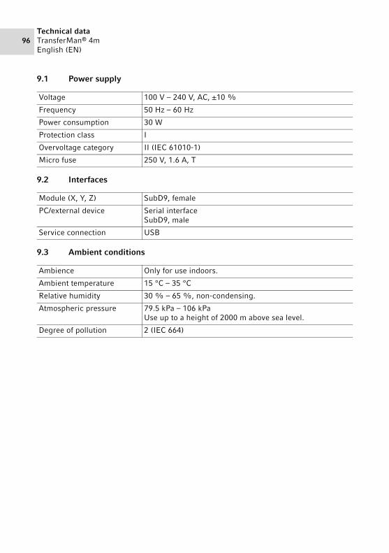
96Technical dataTransferMan® 4mEnglish (EN)
9.1 Power supply
9.2 Interfaces
9.3 Ambient conditions
Voltage 100 V – 240 V, AC, ±10 %
Frequency 50 Hz – 60 Hz
Power consumption 30 W
Protection class I
Overvoltage category II (IEC 61010-1)
Micro fuse 250 V, 1.6 A, T
Module (X, Y, Z) SubD9, female
PC/external device Serial interfaceSubD9, male
Service connection USB
Ambience Only for use indoors.
Ambient temperature 15 °C – 35 °C
Relative humidity 30 % – 65 %, non-condensing.
Atmospheric pressure 79.5 kPa – 106 kPaUse up to a height of 2000 m above sea level.
Degree of pollution 2 (IEC 664)

Transport, storage and disposalTransferMan® 4m
English (EN)97
10 Transport, storage and disposal10.1 Disassembling and packing the micromanipulatorAbb. 10-1:Base padding
Fig. 10-1: Base padding
Abb. 10-2:Middle padding
Fig. 10-2: Middle padding
9 Control panel
10 Power cable
11 Connecting cable
3 Z-module
4 Y-module with YZ connector
5 Swivel joint
6 X-module
7 Angle head
8 Cable sheathing
1011
09
9
1110
0307
08
06
05
04
5
8
6
7
3
4

98Transport, storage and disposalTransferMan® 4mEnglish (EN)
Abb. 10-3:Lid padding
Fig. 10-3: Lid padding
Prerequisites• The original box with foam padding is available.
1. Center the Z-module, X-module and Y-module manually with the joystick.The module housing and the movable rail must be flush.
2. Switch off the micromanipulator at the mains/power switch.3. Pull the power cable and place it in recess 10.4. Unscrew the module plug connections from the control board.5. Unscrew the connection to the external device and place it in recess 11.6. Place the control board in recess 09.7. Align the joystick so that it is straight and position the middle padding with the recess
above the joystick.8. Remove the cable sheathing and place it in recess 08.9. Remove the capillary holder.10.Loosen and pull off the angle head.11.Re-tighten the screws at the angle head and place them in recess 07.12.Undo the screw on the swivel joint.13.Pull off the X-module with swivel joint.14.Loosen the second screw at the swivel joint and pull the swivel joint from the
X-module.15.Tighten both screws at the swivel joint and place the swivel joint in recess 05.16.Place the X-module in recess 06.17.Loosen the screw connecting the YZ connector to the Z-module.
1 Operating manual 2 Tool bag
01
02
21

Transport, storage and disposalTransferMan® 4m
English (EN)99
18.Pull off the YZ connector with Y-module.The YZ connector remains at the Y-module.
19.Tighten the screws at the YZ connector. 20.Place the Y-module with YZ connector in recess 04.21.Loosen the screw connecting the Z-module holder to the Z-module and pull off the
Z-module.22.Tighten the screw of the Z-module holder.23.Place the Z-module in recess 03.24.Insert the lid padding.25.Place the tool bag in recess 02.26.Close the box and send it to the authorized service.
10.2 Storage
10.3 Decontamination before shipment
If you are shipping the device to the authorized Technical Service for repairs or to your authorized dealer for disposal please note the following:
Air temperature Relative humidity Atmospheric pressure
In transport packaging
-25 °C – 55 °C 10 % – 95 % 70 kPa – 106 kPa
Without transport packaging
-5 °C – 45 °C 10 % – 95 % 70 kPa – 106 kPa
WARNING! Risk to health from contaminated device
1. Observe the information on the decontamination certificate. You can find it as a PDF document on our webpage (www.eppendorf.com/decontamination).
2. Decontaminate all the parts you would like to dispatch.3. Include the fully completed decontamination certificate in the package.
Disinfect the device (see Disinfection/decontamination on p. 94).

100Transport, storage and disposalTransferMan® 4mEnglish (EN)
10.4 Transport
Carry out the following steps before transport:
1. Move modules into center position.The movable rail must not protrude over the module.
2. Dismantle the module unit before transport.3. Only use original packaging for transport.
10.5 Disposal
If the product needs to be disposed of, the relevant legal regulations must be observed.
Information on the disposal of electrical and electronic devices in the European Community:
Within the European Community, the disposal of electrical devices is regulated by national regulations based on EU Directive 2012/19/EU pertaining to waste electrical and electronic equipment (WEEE).
According to these regulations, any devices supplied after August 13, 2005, in the business-to-business sphere, to which this product is assigned, may no longer be disposed of in municipal or domestic waste. To document this, they have been marked with the following marking:
Because disposal regulations may differ from one country to another within the EU, please contact your supplier if necessary.
NOTICE! Damage to the control board as a result of incorrect handling.
Grasp the control board on the housing.Do not lift the control board using the joystick.Never place the control board on the joystick.
Air temperature Relative humidity Atmospheric pressure
General transport -25 °C – 60 °C 10 % – 95 % 30 kPa - 106 kPa
Air freight -40 °C – 55 °C 10 % – 95 % 30 kPa - 106 kPa

Ordering informationTransferMan® 4m
English (EN)101
11 Ordering information11.1 Accessories for TransferMan 4m
11.2 Microscope adapter
Order no. (International)
Order no. (North America)
Description
Spare parts kit5192 071.005 5192071005 1 slider (complete), 2 machine screws M2.5×6
(swivel joint), 2 set screws (angle head), 2 compression springs (knurled screw angle head)Positioning aid2 pieces
5192 072.001 5192072001 for universal capillary holder
Order no. (International)
Order no. (North America)
Description
Adapter for microscopeLeica 1
5192 301.000 5192301000 DMi8, DMI3000 B, 3000 M, 4000 B, 5000 B, 5000 M, 6000 B, DM IRB E, DM IRE 2 Adapter for microscopeLeica 2
5192 302.007 5192302007 DM IL LED, HCAdapter for microscopeOlympus 1
5192 306.002 5192306002 IX50, IX51, IX70, IX80, IX81Adapter for microscopeOlympus 2
5192 307.009 5192307009 IX53 IX3-ILL, IX73 IX3-ILL, IX83 IX3-ILLAdapter for microscopeOlympus 3
5192 308.005 5192308005 IX53 IX2-ILL30Adapter for microscopeNikon 1
5192 316.008 5192316008 Eclipse Diaphot 200, 300, Eclipse Ti-E, Ti-U, Ti-S, TE200, TE300, TE2000Adapter for microscopeNikon 2
5192 317.004 5192317004 Eclipse Ts2RAdapter for microscopeNikon 3
5192 318.000 5192318000 Eclipse Ti2-U, Ti2-A, Ti2-E

102Ordering informationTransferMan® 4mEnglish (EN)
11.3 CellTram 4m and accessories
Adapter for microscopeZeiss 1
5192 311.006 5192311006 AxioObserver 3, 5, 7, AxioObserver A1, D1, Z1, Axiovert 200Adapter for microscopeZeiss 2
5192 312.002 5192312002 Axio Vert.A1
For availability in your country please contact your local distributor.
Order no. (International)
Order no. (North America)
Description
5196 000.021 5196000021 CellTram 4m Air5196 000.048 5196000048 CellTram 4m Oil5196 061.004 5196061004 Injection tube Air
White ring mark, I.D. 0.5 mm, length 1.3 m5196 089.006 5196089006 Injection tube Oil
Blue ring mark, I.D. 1.0 mm, length 1.3 mFilling and Cleaning setincl. filling tube, Luer lock adapter, 2 syringes
5196 088.000 5196088000 for CellTram 4
Order no. (International)
Order no. (North America)
Description

IndexTransferMan® 4m
English (EN)103
Index
AAmbient conditions ................................ 96Application screen.................................. 60
CCable....................................................... 52Capillary
Replacing.......................................... 66Cleaning ................................................. 93
DDecontamination .................................... 99Disinfectant ............................................ 94Display
Coordinates ...................................... 58Menu ................................................ 59Parameter ......................................... 59
Disposal ................................................ 100
FFirst set-up ............................................. 53Function
Change appl ...................................... 87Clean ................................................. 79Function ............................................ 84Home ................................................ 77Installation ........................................ 82Service............................................... 88Softkeys ............................................. 85Speed ................................................ 75Step injection..................................... 76
IInitialization............................................ 65Installation
First set-up ....................................... 53Installation parameters..................... 53Selecting the location ....................... 29
LLimit
Horizontal limit .................................74Lower limit ........................................73Upper limit ........................................73Vertical limit......................................72X-limit ...............................................74Z-Limit...............................................73
MMain menu ..............................................63
PParameter input ......................................64Position
Deleting.............................................72positions............................................71Save...................................................70
RReset .......................................................89
SSample
Change ..............................................68Selecting the location..............................29Service
Safety inspections .............................94Service provisions .............................94
Software navigation ................................64Standby ...................................................65Storage....................................................99Switching off ...........................................65Switching on ...........................................65
UUnpacking...............................................28Upper Limit .............................................73

IndexTransferMan® 4mEnglish (EN)
104
XX-limit..................................................... 74
ZZ limit ..................................................... 73

Certificates


Evaluate Your Manual
Give us your feedback.www.eppendorf.com/manualfeedback
Your local distributor: www.eppendorf.com/[email protected] · www.eppendorf.com
Eppendorf AGBarkhausenweg 122339 HamburgGermany