Embed Size (px)
Citation preview

Transduction of the Electrocardiogram
EEE 120 – Electronic Instrumentation

Topics Covered
Electrophysiology of the Heart
Ionic to Electronic Transduction
Instrumentation Design Considerations
Electrical Safety Considerations

The Conduction System of the Heart (Origin of the Electrocardiogram)

Transmembrane Potential and Ionic Conductances

Lead II Electrocardiogram Recording

ECG Waveform Nomenclature

ECG Timing and Relationship to Electrical Conduction

The Electrode-Skin Interface

ECG Recording Circuit

Typical Lead II ECG Recording

Electrode Potential Stability

Electrode Materials and Offset Potentials (mV)

Sintered Ag/AgCl Electrodes

EMG and 60 Hz Interference

ECG Bandwidth Requirements
!"#$%&'(")*+#%,-",(./**0102*3*400*561*57#8(*9#(7*:&%"(&8*+#%,-",(./**012*3*;0*561*

Effects of Inadequate Bandwidth

ECG Amplitude Range (mV x 10)

Burr Brown (Texas Instruments) INA 121 Instrumentation Amplifier

In-Amp with Isolated Ground Circuit

Signal and 60 Hz Noise Level

Sampling Rate and the Phenomenon of Aliasing

Aliasing Analysis

UAF 42 Universal Active Filter

UAF42 2nd Order Low-pass Filter (example)
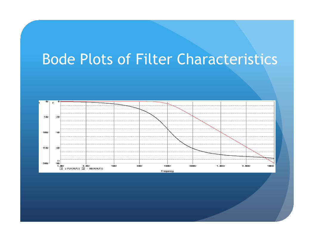
Bode Plots of Filter Characteristics
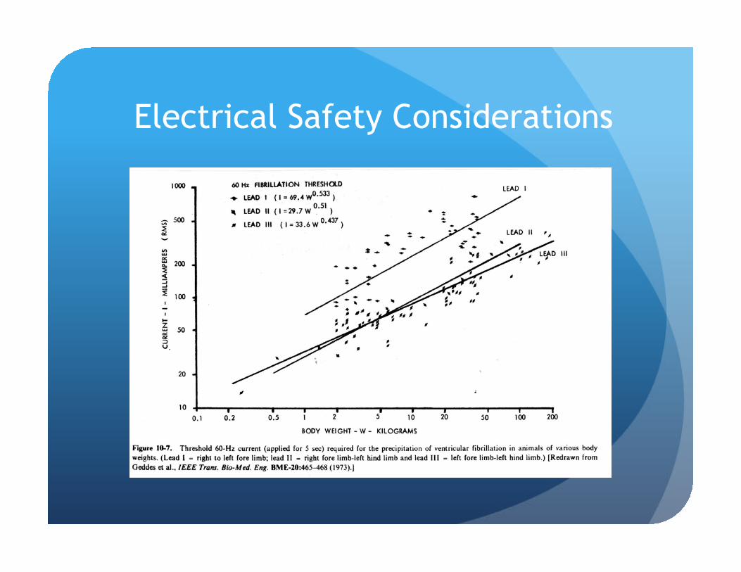
Electrical Safety Considerations

Patient Leakage Current Standards

Isolation Transformer

Isolation Amplifiers

Analog Devices AD 210 ISO Amplifier Functional Diagram

Driven Ground Circuit
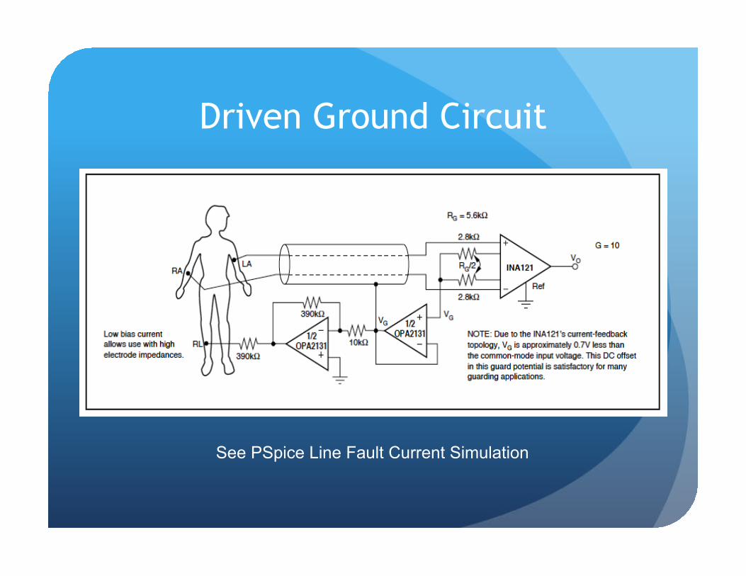
Driven Ground Circuit
See PSpice Line Fault Current Simulation

PSpice Line Fault Simulation Circuit
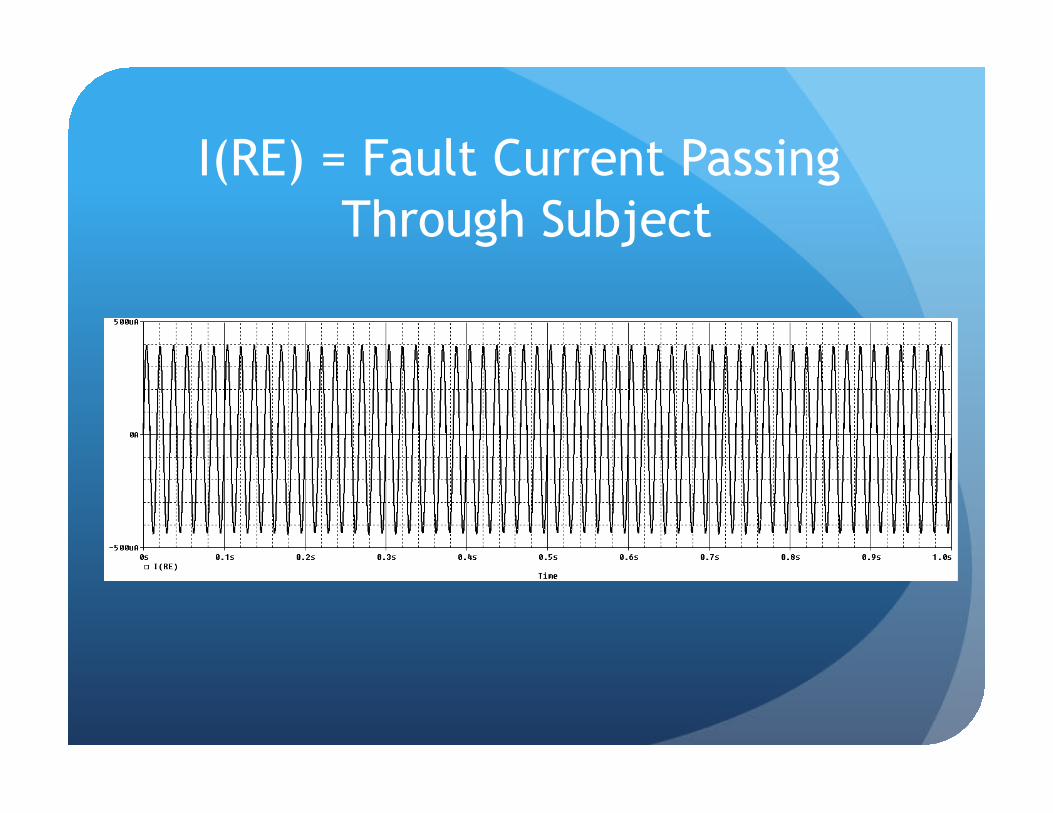
I(RE) = Fault Current Passing Through Subject


![UFC%203-560%20Electrical%20Safety[1] Copy.pdf](https://img.dokumen.tips/doc/110x75/577cc4291a28aba7119854b6/ufc203-56020electrical20safety1-copypdf.jpg)


