Embed Size (px)
Citation preview

Model 8175
Transducer Interface Unit (TIU) For Use with the PCB® Series 5400 Wheel Force Transducer
Instruction Manual Highlights
PCB Load & Torque, Inc. Toll-Free in USA 866-684-7107 716-684-0001 www.pcbloadtorque.com
Wheel Force Transducer System Overview System Components Transducer Interface Unit Introduction Lights and controls Power Switch Zero Light Shunt Light Mode Lights Coordinates Lights Fault Light Position Switch Connectors Output Channels Zero and Shunt Control Functions TIU Data Flow Multiple TIU Applications Power Requirements Balancing—Zeroing Zeroing on the Hoist Rolling Zero on the Road Stationary Zero Verifying the Zero Procedure
Factory Calibration Shunt Calibration Sequence Additional Checks Sensor Offset Check Insulation Check Crosstalk Weatherproofing Additional Considerations Wheel Offset Considerations Rotational Restraints Sampling Frequency Understanding Global Vehicle Coordinates Forces and Moments Calculations of the Resolved Signals Coordinate Transformation to Wheel Mid-Plane Technical Information Troubleshooting WFT Measurement System Cable TIU Signal Out Connector Pinout TIU Power Connector Pinout

The Wheel Force Transducer System from PCB Load & Torque, Inc. measures 6-axes of forces and mo-ments on a vehicle wheel. It offers quick setup and calibration, with accurate and dependable measure-ment of the road loads encountered by the vehicle, despite rigorous road load conditions. There are four basic components mounted on the axle: the Wheel Force Transducer (WFT), the WFT Amplifier, the modified rim, and the hub adapter. Because of the industry standard bolt pattern of heavy trucks, the design of the WFT for use with heavy trucks includes an integral hub adapter. The complete assembly (WFT, amplifier, hub adapter, and modified rim) mounts on the hub of the vehicle. All forces and mo-ments acting on the vehicle at the tire patch must pass through the WFT before being transferred to the vehicle hub.
Six individual strain gage bridges on the WFT meas-ure the forces and moments. The WFT is designed for low crosstalk between channels, and features spe-cial temperature compensation that greatly minimizes the effect of temperature. The amplifier section pro-vides signal conditioning to amplify the output signal before transfer to the data acquisition system.
Transfer of the output signals from the rotating WFT to the vehicle is typically through a multiple circuit slip ring that is integral to the amplifier. Optional telemetry systems are available.
The WFT measures the forces and moments in a spinning coordinate system. The WFT uses SAE ve-hicle coordinates where the X-axis is straight ahead (vehicle moving forward), the Y-axis is to the right, and the Z-axis is down. The output from the X- and Z-axes appear as sine and cosine waves as the WFT rotates. The PCB® Wheel Force Transducer System converts this data into global vehicle coordinates.
The Transducer Interface Unit (TIU) handles the con-version of the output signals into global vehicle coor-dinates. The TIU also coordinates zero offset com-pensation and calibration for both rotating (test track) and non-rotating (test rig) applications. Shunt calibra-tion is provided to ensure accuracy. The user selects which side of the vehicle the WFT is placed and the conversion is made to keep the output signals in SAE coordinates as the loads are measured at the tire patch. If the system falls out of tolerance, Error checking alerts the user .
The WFT system is composed of the following com-ponents, which are illustrated in Figures 1 through 8.
• Wheel Force Transducer (WFT, passenger car, light truck, medium truck, heavy truck, extra heavy truck, or military vehicle)
• Modified Rim
• Hub Adapter
• Amplifier and Slip Ring Assembly
• Transducer Interface Unit (TIU)
• WFT Signal Cable
• TIU Power Cable
• TIU-Data Acquisition Cable
Figure 1. Wheel Force Transducer (WFT) Note inner ring bolt pattern for hub adapter, and outer ring
bolt pattern for modified rim.
Figure 2. Modified Rim Comes in various sizes to match test vehicle; mounts on
outer ring of WFT.
WHEEL FORCE TRANSDUCER SYSTEM OVERVIEW
SYSTEM COMPONENTS
2 PCB Load & Torque, Inc. Toll-Free in USA 866-684-7107 716-684-0001 www.pcbloadtorque.com

Figure 3. Hub Adapter Sized to fit vehicle; mounts on inner ring of WFT
Figure 4. Amplifier and Slip Ring Assembly (also available with Telemetry); Contains signal conditioning for WFT and angle encoder; provides amplified output signals to data
acquisition equipment; mounts on outer face of WFT.
Figure 5. Transducer Interface Unit (TIU)
Figure 6. Signal Cable, WFT to TIU
Figure 7. TIU Power Cable; provides power from vehicle to TIU.
Figure 8. TIU to Data Acquisition Equipment Cable
One wheel force Transducer Interface Unit (TIU) is required for each WFT. This unit handles coordinate transformation and the interface to the data acquisi-tion system. A zero procedure automates the sensor-offset adjustment and options allow the sensor to be used in both rotating or non-rotation modes. The user selects which side of the vehicle the sensor is placed and the TIU makes the necessary transformation to keep the output in the proper SAE coordinates. Error checking is used to alert the user if the system is out of tolerance. Finally, a shunt procedure calculates output sensitivities and allows the user to record shunt calibration values. The front panel of the TIU is illustrated in Figure 9.
Figure 9. TIU Front Panel
TRANSDUCER INTERFACE UNIT INTRODUCTION
PCB Load & Torque, Inc. Toll-Free in USA 866-684-7107 716-684-0001 www.pcbloadtorque.com 3

All controls located on top of the enclosure are mo-mentary contact switches. They correspond to the labels located adjacently on the front panel. Power and position controls are located on the front panel.
Caution
It is good practice to first connect all cables to the TIU electronics before powering it up. If this is not done,
possible damage may occur. In addition, the TIU reads important transducer information from the am-plifier package at startup. Incorrect offsets and gain settings may be used if this information is not read.
The power switch on the right side of the panel turns the power on and off. When the TIU is turned on, it defaults to Run Mode with the Vehicle Coordinates. This will be indicated by green lights on the front panel. Sensor offsets, sensitivities and other informa-tion are read from the smart sensor during power up.
The Zero light indicates the module is performing a zeroing sequence, which is started by pressing the Zero button on top of the enclosure, above the ZERO light. This button is only active in Setup Mode. The light is also used to indicate an error in the zeroing sequence when used in conjunction with the Fault light. The zeroing sequence records data and calcu-lates an offset value. This offset is recorded into the smart chip located in the amplifier package so it is not lost when power is interrupted or a different TIU is used. The TIU uses 2 or 8 revolutions of the WFT to calculate the offset. If the wheel is not turning when the Zero button is pressed, the calculation will be based off of the next 2 revolutions. If the TIU senses the wheel is turning, it uses 8 revolutions to get a bet-ter on-road-averaged value.
The Shunt light indicates the module is performing a shunt sequence, which is started by pressing the Shunt button on top of the enclosure. This button is only active in Setup Mode. The light is also used to indicate an error in the shunt sequence when used in conjunction with the Fault light. The shunt sequence commands the amplifier package to pull in a shunt calibration resistor at each strain gage bridge in the WFT. The TIU reads the voltage change due to the
shunt, and adjusts the gain of each channel to match the sensitivity of the WFT. This calculated gain is re-corded in the smart chip located in the amplifier pack-age so it is not lost when power is interrupted or a different TIU is used.
The Mode lights indicate whether the module is in Setup or Run Mode. The Mode button on top of the enclosure toggles between the modes. Run Mode is used whenever data is being collected. Setup Mode is only used when the transducer is being set up or when the operator is checking the transducer offsets. Zero and Shunt sequences cannot be started unless the TIU has been switched to Setup mode.
The Wheel and Vehicle lights indicate whether the output data is in wheel or vehicle (spindle) coordi-nates. The button on top of the enclosure toggles from one to the other. Wheel coordinates output the data directly from the wheel. This is used during labo-ratory testing when the transducer is not spinning. Vehicle coordinates transform the data from the wheel coordinates to vehicle coordinates. This is used for on-vehicle tests where the wheel is spinning.
The fault light indicates there is a problem with the module. It can be lit in conjunction with other lights or by itself. More information is available in the trouble shooting section of this manual.
The Position rotary switch indicates to the module which side of the vehicle the sensor is on. The mod-ule uses different coordinate transformation equations for the right and left sides of the vehicle. There are 10 possible positions listed on the switch, 5 for right and 5 for the left. The multiple positions are for keeping track of which TIU is used for which wheel when mul-tiple enclosures are stacked up.
Connectors, located on the back panel of the TIU, are for power, ground, sensor cable, and signal out. The connectors located on top and bottom of the enclo-sure are used to connect multiple TIU together. The rear panel of the TIU is illustrated in Figure 9.
Lights and Controls
Power Switch
Zero Light
Shunt Light
Mode Lights
Coordinates Lights
Fault Light
Position Switch
Connectors
4 PCB Load & Torque, Inc. Toll-Free in USA 866-684-7107 716-684-0001 www.pcbloadtorque.com

Figure 9. TIU Rear Panel
Eight analog outputs are available at the D-Sub con-nector labeled SIGNAL OUTPUTS shown in Figure 9. The first 6 channels are for force and moments about the x, y, and z axes. The last 2 are Wheel velocity and Wheel position.
Zero and Shunt Control Functions
Table 1 below shows different possible zero proce-dures that result with different Mode and Coordinates settings.
TIU Data Flow
The road load data measured by the WFT is proc-essed inside the TIU prior to being sent to the data acquisition system.
Figure 10 illustrates the flow of data into and out of the TIU electronics.
Sensitivity adjustments are always performed to the data inside the Coordinate Transformation electron-ics. Offset adjustment and coordinate transformation are not always performed. Table 2 summarizes these states.
One TIU is used with each WFT. When outfitting a vehicle with two or more WFTs, the appropriate num-ber of TIUs are stacked together. Latch studs are mounted on top of the TIU enclosures and a latching mechanism is provided on the bottom. Thus, when the TIU modules are set on top of each other, they latch together. A button on each side of the enclosure releases the latches. Electrical connections are made via the D-sub connectors mounted on top and bottom of the enclosure. When not stacked, it is recom-mended the dust covers provided with the enclosures be used to cover the D-sub connectors. This will pro-tect the connectors and reduce the chance of electri-cal damage to the electronics.
The TIUs communicate with each other using a CAN bus interface. This allows the operator to control all of the TIUs with one set of controls. Notice the control buttons are located on top of the enclosure and the uppermost unit controls all functions.
A base is available to provide better stability and tie down locations. This base also protects the D-sub connector on the bottom TIU.
Figure 11. Multiple TIU Stack
The power supply cable can be connected to any one of the TIUs, which will then supply power to the rest of the units in the stack. Each TIU retains its own power switch and must be turned on individually. Up
Table 1. Zero and Shunt Control Function
Zero Shunt Mode Coordinates
N/A N/A Run Wheel
N/A N/A Run Vehicle
Stationary Shunt Setup Wheel
Rolling Shunt Setup Vehicle
Multiple Transducer Interface Unit Applications
Output Channels
Zero and Shunt Control Functions
Transducer Interface Unit Data Flow
Table 2. Output Channel; Offset, Sensitivity and Data Transformation Function
Control States Outputs
Mode Coordinates Offset Adjustment
Sensitivity Adjustment
Coordinate Transform
Run Wheel Yes Yes No
Run Vehicle Yes Yes Yes
Setup Wheel No Yes No
Setup Vehicle No Yes No
PCB Load & Torque, Inc. Toll-Free in USA 866-684-7107 716-684-0001 www.pcbloadtorque.com 5

to six TIUs can be stacked together. If you want to stack more together, please contact PCB Load & Torque, Inc. to discuss your specific application.
Power Requirements
The TIU requires 10 to 36 VDC power. Power draw is less than 1.5 amperes at 12 volts for each TIU.
A power cable is provided with each TIU. This cable is fused at the end closest to the vehicle power sup-ply. If a replacement cable is made, be sure to in-clude a fuse.
Balancing - Zeroing
An electrical balance is critical to assure accuracy of wheel load measurements. Any electrical zero offset in the transducer or amplifier can introduce significant errors in the measurements. When measurements that are made on the rotating transducer are trans-formed to the stationary vehicle coordinate system, any zero offsets produce errors that are periodic at once-per-revolution. It is therefore important to re-duce all zero offsets to a minimum.
The wheel load transducer is electrically balanced during manufacture. It is then temperature compen-sated to have minimum unbalance up to 175°F (80°C). The amplifiers and TIU are also designed to have minimal thermal offset over a wide temperature range.
The TIU has a Zero feature that automates the zero-ing process. With any of the zeroing methods used below, it is recommended the sensors be exercised before any zeroing is done. To exercise the transduc-ers, simply drive the vehicle around a parking lot.
The three zeroing procedures are described in the following three sections.
Zeroing on the Hoist
This Zeroing method uses the weight of the wheel and tire to determine the zero offsets. This method is recommended for best accuracy.
Caution While it does not matter which direction you turn the
wheel during the zero sequence, it will cause an error if the direction of rotation is reversed during the zero-ing sequence. Remember when turning one wheel on
a drive axle, the wheel on the other side will turn in the opposite direction. This is OK as long as the
wheel does not change direction of rotation.
1. Turn on the TIU.
2. Lift the tires clear of the ground.
3. Press the “Setup Mode” button. The blue “Setup Mode” light is illuminated.
4. Press the “Zero” button. The amber “Zero” light is illuminated.
Note: The wheel must not be rotating when the “Zero” button is pressed.
Caution While it is not important the wheel be turned at a
steady rate, do not impart excessive acceleration or deceleration to the wheel while turning it. This may cause calculation errors. To reduce errors, the TIU uses position-based sampling for this procedure.
5, Rotate the sensor. When rotating the sensor, never apply force to the tire itself. This can cause an error in the zero calculations. Always apply force to the amplifier package only. Rotate in one direction until the amber “Zero” light goes out, this should take 2 revolutions.
6, When using more than one sensor with stacked TIU modules, you may rotate each sensor inde-pendently.
7. To zero only one wheel, you will need to turn off the TIU electronics on the wheels that you do not want to zero, or un-stack them.
When the TIU completes the zero procedure, it will write the calculated offset value to the smart chip lo-cated in the amplifier. This way the sensor does not need to be zeroed every time the power is interrupted or if a different TIU module is used with the sensor.
Rolling Zero on the Road
The Rolling Zero method uses the weight of the vehi-cle to determine the zero offsets. The FY (Lateral) transducer channel may have real, non-zero values during this mode of operation due to the effects of toe-in and tire conicity. The MY (Torque) may also have a real non-zero value due to driveline torque and brake or seal drag. Use this rolling zero method only when a lower level of accuracy can be tolerated.
1. Press the “Setup Mode” button. The blue “Setup Mode” light is illuminated.
2. Drive the vehicle along a smooth and level sec-tion of road or parking lot at a steady state.
3. Press the “Zero” button. The amber “Zero” light will illuminate.
Power Requirements
BALANCING — ZEROING
Zeroing on the Hoist
Rolling Zero on the Road
6 PCB Load & Torque, Inc. Toll-Free in USA 866-684-7107 716-684-0001 www.pcbloadtorque.com
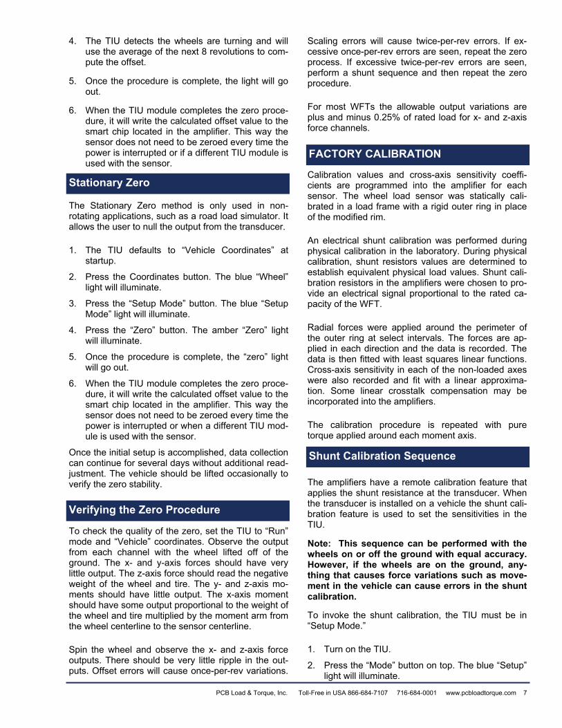
4. The TIU detects the wheels are turning and will use the average of the next 8 revolutions to com-pute the offset.
5. Once the procedure is complete, the light will go out.
6. When the TIU module completes the zero proce-dure, it will write the calculated offset value to the smart chip located in the amplifier. This way the sensor does not need to be zeroed every time the power is interrupted or if a different TIU module is used with the sensor.
Stationary Zero
The Stationary Zero method is only used in non-rotating applications, such as a road load simulator. It allows the user to null the output from the transducer.
1. The TIU defaults to “Vehicle Coordinates” at startup.
2. Press the Coordinates button. The blue “Wheel” light will illuminate.
3. Press the “Setup Mode” button. The blue “Setup Mode” light will illuminate.
4. Press the “Zero” button. The amber “Zero” light will illuminate.
5. Once the procedure is complete, the “zero” light will go out.
6. When the TIU module completes the zero proce-dure, it will write the calculated offset value to the smart chip located in the amplifier. This way the sensor does not need to be zeroed every time the power is interrupted or when a different TIU mod-ule is used with the sensor.
Once the initial setup is accomplished, data collection can continue for several days without additional read-justment. The vehicle should be lifted occasionally to verify the zero stability.
Verifying the Zero Procedure
To check the quality of the zero, set the TIU to “Run” mode and “Vehicle” coordinates. Observe the output from each channel with the wheel lifted off of the ground. The x- and y-axis forces should have very little output. The z-axis force should read the negative weight of the wheel and tire. The y- and z-axis mo-ments should have little output. The x-axis moment should have some output proportional to the weight of the wheel and tire multiplied by the moment arm from the wheel centerline to the sensor centerline.
Spin the wheel and observe the x- and z-axis force outputs. There should be very little ripple in the out-puts. Offset errors will cause once-per-rev variations.
Scaling errors will cause twice-per-rev errors. If ex-cessive once-per-rev errors are seen, repeat the zero process. If excessive twice-per-rev errors are seen, perform a shunt sequence and then repeat the zero procedure.
For most WFTs the allowable output variations are plus and minus 0.25% of rated load for x- and z-axis force channels.
Factory Calibration
Calibration values and cross-axis sensitivity coeffi-cients are programmed into the amplifier for each sensor. The wheel load sensor was statically cali-brated in a load frame with a rigid outer ring in place of the modified rim.
An electrical shunt calibration was performed during physical calibration in the laboratory. During physical calibration, shunt resistors values are determined to establish equivalent physical load values. Shunt cali-bration resistors in the amplifiers were chosen to pro-vide an electrical signal proportional to the rated ca-pacity of the WFT.
Radial forces were applied around the perimeter of the outer ring at select intervals. The forces are ap-plied in each direction and the data is recorded. The data is then fitted with least squares linear functions. Cross-axis sensitivity in each of the non-loaded axes were also recorded and fit with a linear approxima-tion. Some linear crosstalk compensation may be incorporated into the amplifiers.
The calibration procedure is repeated with pure torque applied around each moment axis.
Shunt Calibration Sequence
The amplifiers have a remote calibration feature that applies the shunt resistance at the transducer. When the transducer is installed on a vehicle the shunt cali-bration feature is used to set the sensitivities in the TIU.
Note: This sequence can be performed with the wheels on or off the ground with equal accuracy. However, if the wheels are on the ground, any-thing that causes force variations such as move-ment in the vehicle can cause errors in the shunt calibration.
To invoke the shunt calibration, the TIU must be in “Setup Mode.”
1. Turn on the TIU.
2. Press the “Mode” button on top. The blue “Setup” light will illuminate.
Stationary Zero
Verifying the Zero Procedure
FACTORY CALIBRATION
Shunt Calibration Sequence
PCB Load & Torque, Inc. Toll-Free in USA 866-684-7107 716-684-0001 www.pcbloadtorque.com 7

3. If the vehicle is sitting on the ground, be sure there is no movement in the vehicle during this sequence.
4. Press the “Shunt” button on top. The amber “Shunt” light will illuminate.
5. The output from the TIU will go high for 4 sec-onds, return to zero for 4 seconds, go low for 4 seconds, then return to zero once the sequence is complete.
The TIU uses the shunt to calculate a scale factor for the output, force and moment-channels. This scale factor is recorded into the smart chip located in the amplifier electronics. This ensures the sensitivity does not need to be recalculated every time power is inter-rupted or if a different TIU is used.
If the new sensitivity differs from the factory sensitivity by more than two percent, the fault light will illuminate and the “Shunt” light will stay lit. See the trouble-shooting section of this manual for more information.
The calibration sheet lists sensitivity in lbs/Volt (or N/Volt) and a shunt value in pounds (or Newtons) for each channel. If desired, the user may check the sen-sitivity by recording the outputs during a shunt se-quence and calculating the delta (magnitude of change from low to high). The shunt value listed in the calibration sheet is defined as half of this delta.
Conduct the in-field checkout by parking the vehicle on a scale and comparing the transducer outputs with scale values. The scale values will differ from the out-put of the sensor by a little more than the weight of the tire and rim adapter. Physical re-calibration ser-vices are available from PCB Load & Torque, Inc.
1. Remove hub and wheel adapters. Hub and Wheel adapters can cause a small shift in trans-ducer offset when they are bolted up. This is nor-mal and the sensor will return to its original offset once they are removed.
2. Set the sensor flat on the bench.
3. Connect the amplifier to the sensor.
4. Connect the cable to the slip ring and TIU.
5. Turn on the TIU
6. Press the Mode button to put the TIU into Setup mode.
7. Record the output for each channel.
Insulation Check
Insulation resistance of the wheel load transducer bridge circuits to the flexure should be checked occa-sionally or if malfunction is suspected. The insulation resistance should be greater than 1000 M-ohms. Lower insulation resistance values may result from contamination of the connectors or breakdown of the strain gage insulation. If care is taken to clean the connector area and low values persist the transducer should be returned to PCB Load & Torque, Inc. for correction and re-calibration. The pinout is listed in Table 3 below.
There are two transducer-to-amplifier connectors. These are labeled on the front of the amplifier pack-age.
Crosstalk
The cross-axis sensitivity was measured in a rigid laboratory test fixture with companion amplifiers. Some crosstalk compensation may be included in the amplifiers. The system was shipped with all cross-axis sensitivity less than two percent. This means that if a full-scale force or moment is applied to one axis, less than 2 percent of the full-scale value of the other 5 axes will result. For example, one hundred (100) pounds of radial force will produce less than 2 ft-lb of apparent moment and that one hundred lb-ft moment will produce less than 2 lb. of apparent force.
Table 3. Wheel Force Transducer-to-Amplifier
Connector A Connector B Pin Axis Function Axis Function
I Fx +Power Fz +Power
2 Fx -Power Fz -Power
3 Fx +Signal Fz +Signal
4 Fx -Signal Fz -Signal
5 NC NC
6 NC NC
7 Mz +Power Mx +Power
8 Mz -Power Mx -Power
9 Mz +Signal Mx +Signal
10 Mz -Signal Mx -Signal
11 NC NC
12 Fy +Power My +Power
13 Fy -Power My -Power
14 Fy +Signal My +Signal
15 Fy -Signal My -Signal
ADDITIONAL CHECKS
Sensor Offset Check
Insulation Check
Crosstalk
8 PCB Load & Torque, Inc. Toll-Free in USA 866-684-7107 716-684-0001 www.pcbloadtorque.com

Weatherproofing
All connectors should be covered with fusion tape to keep water and dust out of the connectors. The con-nectors are designed to be weatherproof but the tape provides some extra protection.
Additional Considerations
Wheel Offset Considerations
Wheel offset from the centerline of the tire to the cen-terline of the transducer produces a moment about the vehicle X-axis due to the vertical load. When con-sidering the load rating of the transducer, this mo-ment is added to the moment produced by side load-ing at the tire patch.
Rotational Restraints
The preferred method of providing a rotational re-straint of the slip ring on a front wheel is by means of a strap that goes up and over the tire to the knuckle or backing plate. A simple rod from the slip ring to a loop on the body is usually sufficient for a rear wheel. Simple rotational restraints with magnetic body brack-ets are available from PCB Load & Torque, Inc.
Sampling Frequency
Much of the work done with load wheels is for wheel or chassis load measurement with a frequency of in-terest below 100 Hz. A sampling rate of 1,000 sam-ples/second and pre-sample filter of 400 Hz. are usu-ally adequate. This gives a sample approximately every 6 inches (15 centimeters) of a wheel traveling at 150 mi/hr. For impulsive loads such as that en-countered when striking a pothole, a sampling rate of up to 4000 samples/second may be necessary to de-fine the peak loads to within a few percent.
Understanding Global Vehicle Coordinates
The Wheel Force Transducer System uses SAE coor-dinates. SAE Coordinates define positive X-axis as out of the front of the vehicle. Positive Y-axis is de-fined as to the driver’s right. Positive Z-axis is defined as into the ground. Positive transducer output is de-fined as a force or moment applied on the hub in the positive direction.
Forces And Moments
The transducer measures three forces, longitudinal, lateral, and vertical and three moments about each of these forces. The Full Scale capacity of each axis will vary depending upon size of transducer. The applica-
tion of the forces at the tire patch to a vehicle moving forward is shown in Figure 12. The measured forces and moments are resolved and transformed into the global vehicle coordinates as described in sections below.
Figure 12. Load Application At The Tire Patch
Calculation of the Resolved Signals
The calculation from unresolved into resolved and transformed signals is required because the rotating wheels have a rotating coordinate system, whereas the global non-rotating (street) coordinates relative to the body are required (refer to Figure 13). Under nor-mal conditions the following signals are acquired.
Figure 13. Global Vehicle Coordinates
Note: The unresolved signals are printed in lower case letters and resolved signals in uppercase letters. The TIU firmware resolves the output signals from the WFT into data that relate to the vehicle position by using the formulas shown below. Users of the WFT system who are not using this software to resolve the signals should refer to these formulas when convert-ing their recorded unresolved signal data for analysis. The formulas are as follows:
1. FX, vehicle left side = -1(fx Cosφ - fz Sinφ) 2. FX, vehicle right side = fx Cosφ - fz Sinφ 3. FY, vehicle left side = fy, unresolved 4. FY, vehicle right side = -fy, unresolved 5. FZ, vehicle left side & right side = fz Cosφ + fx
Sinφ 6. MX, vehicle left side = -1[(mx Cosφ - mz Sinφ) –
a (fz Cosφ + fx Sinφ) + (fy * r)]
Weatherproofing
ADDITIONAL CONSIDERATIONS
Wheel Offset Considerations
Rational Restraints
Sampling Frequency
UNDERSTANDING GLOBAL VEHICLE COORDINATES
Forces and Moments
Calculation of the Resolved Signals
PCB Load & Torque, Inc. Toll-Free in USA 866-684-7107 716-684-0001 www.pcbloadtorque.com 9

7. MX, vehicle right side = (mx Cosφ - mz Sinφ) – a (fz Cosφ + fx Sinφ) + (fy * r)
8. MY, vehicle left side = my, unresolved 9. MY, vehicle right side = -my, unresolved 10. MZ, vehicle left side & right side = (mz Cosφ +
mx Sinφ) + a (fx Cosφ - fz Sinφ) Where: r = the rolling radius in meters. a = the offset in meters between the center-
line of the wheel and the centerline of the WFT. Correcting for this offset is important to ensure accuracy of the MX and MZ data.
The TIU resolves the forces and moments to the in-tersection of the axis of rotation and a plane through the middle of the sensor ring. The forces and mo-ments can be resolved to the intersection of the axis of rotation and the mid-plane of the wheel, in the data acquisition system or by post processing. The forces and Y Moment do not change. The X and Z Moments change in relation to the radial force and the distance from the wheel mid-plane to the transducer mid-plane. The equations are listed below.
Right side of the vehicle:
Mxmp = Mxv + Fzv * a
Mzmp = Mzv + Fx * a
Left side of the vehicle:
Mxmp = Mxv - Fzv * a
Mzmp = Mzv - Fx * a
Where:
Mxmp = X Moment at the tire mid plane
Mzmp = Z Moment at the tire mid plane
a = the distance from the sensor centerline to the wheel centerline. This distance must be expressed in either feet or meters to keep the units consistent.
Coordinate Transformation to Wheel Mid-Plane
10 PCB Load & Torque, Inc. Toll-Free in USA 866-684-7107 716-684-0001 www.pcbloadtorque.com

Technical Information
Troubleshooting
Refer to Table 4 to find a solution when trouble-shooting problems with the equipment.
TECHNICAL INFORMATION
Troubleshooting
Table 4. Troubleshooting Symptom Possible Causes Solution
TIU Does not power up when the power switch is turned on.
Fuse on power cord is blown. Replace Fuse with 7.5-ampere automotive fuse and try to power up the TIU again.
Power cord not connected to power.
Check that power cord has power supplied to it and try to power up the TIU again.
Power supply polarity is incorrect. Check polarity, if incorrect, reverse power supply leads and try to power up the TIU again
Fault light illuminates at startup WFT sensor cable not connected properly.
Check WFT sensor cable connections. Cycle power, leave modules off for 5 seconds be-fore turning back on Smart chip communication failure.
Fault light illuminates immediately after a button is pressed.
Internal communication error Cycle power, leave module off for 5 seconds before turning back on Cycle power, leave module off for 5 seconds before turning power back on, Resume operation
After zero sequence, Zero light does not go out and fault light illuminates.
Failure to record data to smart chip
Check cable connections, cycle power, and repeat the zero sequence.
After zero sequence, Zero light goes out but Fault light illumi-nates.
Sensor offset greater than 4 volts. The electronics will still zero the channel that has greater than 4 V offset but it alerts the user. This condition can cause the system output to saturate before it reaches full scale. The Fault light will go out next time the power is cycled.
With wheel off of the ground, change TIU to "Setup" mode and check output voltages. Confirm which channel has an offset greater than 4 V
Unbolt the wheel adapter. if offset goes away, check adapter to see that it is not damaged.
If offset does not go away, unbolt the hub adapter. If offset goes away, check adapter to see that it is not damaged.
If offset does not go away, send sensor in to PCB® Load & Torque, Inc. for Checkout and repair.
Shunt light does not go out and fault light illuminates after a shunt sequence.
Force input to the sensor during shunt sequence causes out of tolerance shunt.
Jack up vehicle, cycle power, and repeat the shunt sequence.
TIU failed to record data in smart chip
Check the cable connections, cycle.power, and repeat the shunt sequence.
Sensor is out of tolerance. Send the sensor in for checkout and calibra-tion.
Data has once-per-revolution waveform.
The zero is not correct. Perform zero procedure.
The tire can have stiffness varia-tions, which will appear as once-per-revolution variations. This is a real force.
If force variation is not acceptable, replace the tire.
Wheel adapter can be bent or out of tolerance. The force is real.
If force variations are not acceptable, replace the wheel adapter.
PCB Load & Torque, Inc. Toll-Free in USA 866-684-7107 716-684-0001 www.pcbloadtorque.com 11

Table 4. Troubleshooting - Cont’d Symptom Possible Causes Solution
Data has twice-per- revolution waveform
The sensitivities are out of toler-ance due to incorrect or corrupted sensitivity values.
Perform the shunt sequence. It is important that no dynamic forces are imposed on the sensor at this time. These forces can come from movement in the vehicle. For best accu-racy, lift the wheel off the ground
One of the strain gage bridges has failed.
Check the outputs during the shunt sequence and check the zero data when the TIU is in setup mode. If the shunt value is not correct or the zero has shifted, send sensor in for checkout and repair.
Fx, Fz, Mx, and Mz channels look like sine waves when wheel is in motion.
TIU is set to wheel coordinates. Check status of lights on front panel. If the “Wheel Coordinates” light is illuminated, press the “Coordinates” button on top to change back to vehicle coordinates. Check outputs
TIU is in setup mode. If the “Setup Mode” Light is illuminated, press the “Mode” button on top to change back to run mode.
Channels, which should have no load, have an offset even after the zero
Data channels have error due to rolling zero procedure.
For best accuracy, perform the zero on the hoist. Further discussion is in the zeroing section of this manual
Incorrect zero, direction of wheel rotation was changed during the zero procedure.
Be sure the wheel is turned only in one direc-tion during the zero procedure
External forces were imposed during the zero procedure on the hoist,
When turning the wheels, be sure to apply force only on the amplifier package. This en-sures that no forces are imposed through the sensor
Incorrect zero, on-the-road zero was performed on a rough surface
Redo the zero procedure. For best accuracy, perform the zero on the hoist.
Data acquisition system has some offset.
Using a voltmeter, check the outputs from the TIU. If the outputs are indeed zero, null the offsets in the data acquisition system.
TIU electronics are damaged. Swap the TIU with another unit, if available, and try to zero it. If the problem goes away, send the TIU in for checkout and repair
Offsets are too large for the TIU to zero them. Damage to sensor.
The wheel may have been damaged. Re-move from the wheel and hub adapters and place on the bench. Change the TIU to setup mode. Check the offset. If it is out of range, send in for checkout and repair.
12 PCB Load & Torque, Inc. Toll-Free in USA 866-684-7107 716-684-0001 www.pcbloadtorque.com

Table 4. Troubleshooting - Cont’d Symptom Possible Causes Solution
Outputs from the TIU module stay zero for all channels even when force is present
TIU is not turned on. Check to see if the TIU is turned on.
Encoder has not found an index pulse.
The output channels stay at zero until the encoder sees an index pulse. Turn tire at least one complete revolution. Check Out-puts.
Signal cable from sensor has been disconnected.
Turn off the TIU, reconnect the cable and turn the TIU back on.
Signal Cable from sensor has been damaged.
Inspect cable for damage. A cable diagram is located in the appendix.
Output cable from the TIU is dis-connected or damaged.
Check connection and inspect cable for dam-age
The data acquisition cabling con-nected improperly.
Check the output from the TIU with a voltme-ter. If the output is correct, check the cabling or data acquisition setup.
The channel offsets change dur-ing use.
A severe event caused some shifting in the bolted joints be-tween the sensor and adapters.
While it is not common, a severe event could cause some offset in channels. Perform the zero sequence.
A severe event overloaded the sensor.
Check the sensor offsets. Remove the wheel and hub adapters. Change theTIU to "Setup Mode" Check the offsets for each channel with a voltmeter. If the offsets have changed, send the sensor in for checkout and possible repair.
Higher or lower than expected output from one or more chan-nels
The data acquisition system sen-sitivities are incorrect.
Check data acquisition system. The correct sensitivities are listed on the calibration sheet.
Incorrect amplifier package Check the correct amplifier package is being used with the sensor.
Sensor is damaged. Check the sensor offsets and shunt values. Send is for checkout and repair if needed.
Amplifier package is damaged Send in for checkout and repair if needed
One or more output channels output incorrect polarity.
Right/Left Switch is not in correct position.
Check to see if switch is correct. Change if needed.
Cable to data acquisition is im-properly connected.
Check the voltage from the TIU. If correct, check pin-out for signal cable to the data ac-quisition system.
Sensitivity is incorrect in the data acquisition system.
Check the voltage from the TIU. If correct, check the sensitivities in the data acquisition system.
Angle reference incorrect Slip Ring is not oriented properly Orient the slip ring so the connector is pointed vertical. The side surfaces of the slip ring should be vertical.
PCB Load & Torque, Inc. Toll-Free in USA 866-684-7107 716-684-0001 www.pcbloadtorque.com 13

WFT Measurement System Cable
The pinouts and functions of the WFT cable are de-scribed in Table 5 below.
TIU Signal Out Connector Pinout
The pinouts for the TIU signal outputs are described in Table 6 below.
TIU Power Connector Pinout
The pinouts for the TIU power cable are described in Table 7 below.
CAUTION A 7.5-ampere fuse is located in the power cable. Be sure to include the fuse if building a new cable.
Table 5. WFT Cable Pinouts
Slip Ring Mating Con-
nector
TIU Module PT06E-16-26P
(SR) Function
A A +15 Volts DC
B B +15 Volts DC C C 15 VDC Common D D 15 VDC Common E E -15 Volts DC F F -15 Volts DC G G Calibration Control H H Smart Sensor J J Fx High K K Fx Common L L Fy High M M Fy Common N N Fz High P P Fz Common R R Mx High S S Mx Common T T My High U U My Common V V Mz High W W Mz Common X X +5 to +20VDC Y Y Ground Z z Output A a a Output B b b Output I c NC Shield
Table 6. 15 Pin D-Sub Connector
Pin Numbers Function
1 Position High 2 Speed High 3 Mz High 4 My High 5 Mx High 6 Fz High 7 Fy High 8 Fx High 9 Position & Velocity Common 10 Mz Common 11 My Common 12 Mx Common 13 Fz Common 14 Fy Common 15 Fx Common
Table 7. Mating Connector for Power: Speak-ON part number: NLT4FX
1+ Not Used 1- Not Used 2+ Power Hi 2- Power Ground
WFT Measurement System Cable TIU Signal Out Connector Pinout
TIU Power Connector Pinout
PCB® Load & Torque, Inc., designs and manufactures a full line of load cell and torque sensors for numerous in-dustries including: aerospace & defense, automotive, medical rehabilitation, material testing, textile, process control, robotics and automation, and more. PCB® offers exceptional customer service, 24-hour technical assis-tance, and a Total Customer Satisfaction guarantee.
Visit www.pcb,com to locate your nearest sales office
Corporate Headquarters 3425 Walden Avenue, Depew, NY 14043-2495 USA
Toll-Free in USA 866-684-7107 24-hour SensorLineSM 716-684-0001
Fax 716-684-0987 E-mail [email protected] www.pcbloadtorque.com
AS9100 CERTIFIED ISO 9001 CERTIFIED A2LA ACCREDITED to ISO 17025 © 2009 PCB Group, Inc. In the interest of constant product improvement, specifications are subject to change without notice. PCB, ICP, Modally Tuned, Spindler, Swiveler and TORK-DISC are registered trademarks of PCB Group. SoundTrack LXT, Spark and Blaze are registered trademarks of PCB Piezotronics. SensorLine is a servicemark of PCB Group. All other trademarks are property of their respective owners. L&T-8175 TIU 1109 Printed in U.S.A.