Embed Size (px)
Citation preview
1
Trans-Cal Industries, Inc.
Model ATS-400
Altitude Reporting Equipment Test Set & Simulator
Operating Manual
Trans-Cal Industries. Inc. 16141 Cohasset Street
Van Nuys, CA 91406-2908 (800) 423-2913*(818) 787-1221*(818) 787-8916FAX
14 September 2004 Document Number: 104010 Rev. D

2
Proprietary Information: This document contains proprietary information, which may not be reproduced, transmitted, or copied without the prior written consent of Trans-Cal Industries, Inc.
©2004 by Trans-Cal Industries, Inc. All rights reserved. Contact Information:
Trans-Cal Industries, Inc. 16141 Cohasset Street Van Nuys, CA 91406-2908
Phone: 818/787-1221 Toll Free: 800/423-2913 FAX 818/787-8916 www.trans-cal.com
Ordering Information:
To receive additional copies of this publication order part number 104010 rev. D, Model ATS-400 Altitude Reporting Equipment Test Set & Simulator Operating Manual
Prepared by: M. Remenih 19 August 2004 Checked by: J. Ferrero III 19 August 2004 Approved by: J. Ferrero 19 August 2004 History of Revision Revision Date Description
A 4 March 2004 Prototype release. B 27 May 2004 Production release. C 19 August 2004 Updated Production release. D 14 September 2004 Add wiring harness diagram.
Materials referenced within this document:
ARINC Specification 429, Published 1 September 1995. TIA/EIA Recommended Standard RS232D, Published January 1987. TIA/EIA Recommended Standard RS422B, Published May 1994. TIA/EIA Recommended Standard RS485A, Published March 1998.

3
Table of Contents
Table of Contents........................................................................................................................ 3 Abbreviations and Symbols ........................................................................................................ 4 Introduction & Equipment Description ...................................................................................... 5 Section 1.0 Specifications........................................................................................................... 6 Section 2.0 Operation.................................................................................................................. 7
2.1 Test Condition One: Standard ICAO Altitude Encoder ................................................... 7 Figure 1 ............................................................................................................................... 8
2.2 Test Condition Two: ICAO Altitude Encoder with RS232 Port ...................................... 9 Figure 2 ............................................................................................................................. 10
Section 3.0 Front Panel Connector Pin Assignments ............................................................... 11 Section 4.0 Power Connections ................................................................................................ 14
Figure 3 ............................................................................................................................. 14 Section 5.0 Front Panel Switch Functions ................................................................................ 15 Section 6.0 Front Panel Rotary Switch Functions .................................................................... 16 Section 7.0 Serial Interface Specifications ............................................................................... 17
7.1 General Characteristics of Serial Data Inputs................................................................ 17 7.2 ARINC 429 Label 203 Protocol ..................................................................................... 18 7.3 ARNAV PROTOCOL .................................................................................................... 20 7.4 MAGELLAN PROTOCOL............................................................................................ 21 7.5 NORTHSTAR PROTOCOL .......................................................................................... 22 7.6 SHADIN PROTOCOL ................................................................................................... 23 7.7 TRIMBLE/GARMIN PROTOCOL................................................................................ 24 7.8 UPS AT PROTOCOL..................................................................................................... 25 7.9 UPS AT LORAN 618 PROTOCOL............................................................................... 26 7.10 Serial Data Matrix......................................................................................................... 27
Section 8.0 Simulation Mode.................................................................................................... 28 Wiring Harness Diagram for the ATS-400 Test Set ................................................................. 30

4
Abbreviations and Symbols
A Amperes AC Advisory Circular ARINC Aeronautical Radio Incorporated ASCII American Standard for Coded Information Interchange ATCRBS Air Traffic Control Radar Beacon System bps Bits per second. EEPROM Electronically Erasable Read Only Memory EIA Electronic Industries Association FAA Federal Aviation Administration FAR Federal Aviation Regulation ft. Distance in feet. GPS Global Positioning System Hz Hertz ICAO International Civil Aviation Organization I.F.F. Identification Friend or Foe In. Hg. Inches of Mercury Kbps Kilobits per Second KHz Kilohertz LSB Least Significant Bit mA Milliamperes max. Maximum MB Millibar MHz Megahertz MFD Multi-Function Display MSL Mean Sea Level min. Minimum ms Time in milliseconds. MSB Most Significant Bit NIST National Institute of Standards and Technology oz Ounce psi Pounds per Square Inch RAM Random Access Memory RS Recommended Standard RTCA RTCA Inc. (formerly Radio Technical Commission for Aeronautics.) SAE Society of Automotive Engineers sec. Time in seconds. SSM Sign, Status Matrix SSR Secondary Surveillance Radar TCI Trans-Cal Industries, Inc. TIA Telecommunication Industries Association TSO Technical Standard Order UUT Unit Under Test Vdc Volts Direct Current VSI Vertical Speed Indicator Ω Electrical resistance measured in Ohms. ºC Temperature in degrees centigrade. ± Plus or minus. § Section ↓ Line Feed ← Carriage Return. Start of message character. End of message character.

5
Introduction & Equipment Description
The TCI Model ATS-400 is designed to test, display and simulate the output of Altitude Reporting Equipment, which conform to the ICAO Standard for SSR Pressure Altitude Transmission. In accordance with the U.S. National Standards for I.F.F. Mark X (SIF)/Air Traffic Control Radar Beacon System SIF/ATCRBS. The ATS-400 will also display the output of altitude reporting equipment which transmit serial data in either RS232, RS422, RS485 or ARINC 429 Label 203. The ATS-400 utilizes an advanced RISC microprocessor to display the output of these devices in both numeric and binary forms, with an input altitude data range covering the full ICAO code from –1000 to +126,000 feet. The ATS-400 may be interfaced with an IBM PC for cross-reference and two-way data communication if required. The ATS-400 can also function in a simulate mode providing altitude data on the ICAO simulate port (connector J1) and RS232 altitude data on a serial data port (connector J4). In this mode, the test set will output altitude data beginning at –1000 feet, then ascend at 6000 feet per minute to 126,000 feet. The ascent may be halted at any altitude by depressing the simulate toggle. The ascending count may be resumed by depressing the simulate toggle again. The ATS-400 in simulate mode, provides the avionics technician with a known good ICAO altitude code source for testing altitude inputs to transponders, GPS, MFD, auto-pilots and other navigation devices. The ATS-400 may be used in the aircraft or on the bench making this an extremely versatile piece of test equipment.

6
Section 1.0 Specifications
Electrical Input Voltage +7.5 to 35Vdc Input Current 400mA Max. Internal Fuse 2A fast blow. Physical Height with cover. 6.16” Width 5.68” Length 10.0” Weight 3.5 lbs. Environmental Operating temp. 0º to +50ºC Storage temp. -20º to +65ºC Humidity 90% Non-Condensing at 50ºC. ICAO Input Port (Connector P1) Pull-Up Voltage +5Vdc Sink Current 2.5mA Code Format ICAO Altitude Transmission
SIF/ATCRBS ICAO Simulate Port (Connector J1) Driver Description “Uncommitted” collectors of 11 discreet transistors. “Pull-Up” Voltage +3 to +40Vdc Max. “Sink” Current 50mA Code Format ICAO Altitude Transmission
SIF/ATCRBS RS232 Input Port (Connector J4) Electrical Format TIA/EIA RS-232 Max. Input Voltage ±15Vdc Impedance 3K to 7KΩ Data Rate 1200 to 9600bps RS232 Simulate Port (Connector J2 Pin 13) Electrical Format TIA/EIA RS-232 Max. Output Voltage ±25Vdc Impedance 3K to 7KΩ Data Rate 1200 to 9600bps RS422/485 Input Port (Connector J2) Electrical Format TIA/EIA RS-422 & 485 Max. Input Voltage -7 to +12Vdc Impedance 12KΩ Min. Data Rate 1200 to 9600bps ARINC 429 Input Port (Connector J3) Electrical Format ARINC 429 (DITS) Max. Input Voltage +1.5 to +13Vdc Impedance 30KΩ Min. Data Rate 12.5kbps

7
Section 2.0 Operation
The ATS-400 is a versatile piece of test equipment, and it would not be practical to cover every possible test condition or set-up within this document. Therefore, only two common test conditions will be described. Please contact the factory for assistance if required.
2.1 Test Condition One: Standard ICAO Altitude Encoder
1. Turn the ATS-400 UUT Power switch to the OFF position.
2. Connect a vacuum/pressure source and control as required.
3. Construct a wiring harness between the altitude encoder and connector P1 of the ATS-400. The P1 connector pin assignments are in listed in §3.0. See figure 1. Refer to the altitude encoder installation manual for specific connector pin assignments.
4. Provide +14 to 28Vdc power to the ATS-400 five-way binding post.
5. Turn the ATS-400 power switch to “AIRCRAFT.” This switch directs the
ATS-400 to receive its power from the five-way binding posts.
6. Move the Strobe switch to the “ON” position. This applies a ground to pin 6 of the P1 connector, enabling the altitude encoder’s outputs.
7. Energize the altitude encoder and the ATS-400 by turning the ATS-400 “UUT
Power” switch to either +14Vdc for 14-volt operation or +28Vdc for 28-volt operation. Selecting the +28Vdc position will direct power to the ATS-400 electronics and to Pin 8 of the P1 connector. Selecting the +14Vdc position will provide power to the ATS-400 electronics and to pin 14 of connector P1. CAUTION! ENSURE THAT POWER IS APPLIED TO THE CORRECT ALTITUDE ENCODER CONNECTOR PIN! ENCODER DAMAGE MAY RESULT!
8. After an initialization message, the ICAO altitude data should be presented on
the bottom line of the two-line display. The top line will display a no serial data input message. Apply vacuum or pressure as required to verify the operation of the unit under test.

8
Figure 1
+14 to +28VDC Power Buss
Altitude ReportingEquipment
Trans-Cal Industries, Inc.
ATS-400 PWR
D2
TRIMBLE
MAGELLAN
N. STAR
UPS AT
RS232
GARMIN
P1
ALTIMETER INPUTDIGITIZER/
OFF
ONSTROBE
J1 J2 J3
ALTITUDE
SERIALSELECT
STARTSIMULATE
INPUT
SELECT
RS422/485
PROTOCOL
TOPUSH
TEST
SIMULATIONOUTPUT
100'
10'
A2
DIGITIZERPROTOCOL
D4 A1 B1A4 B2
RS422/485
ARINC 429
ARINC 429
OFF
100'
1000'HORN
AIRCRAFT
INPUT
BENCH
C4
TxD1
TxD2
C1B4 C2
Altitude Reporting Equipment Test Set and Simulator
Model ATS-400
2A
J4 P2
OFF
DIGITIZERRS232 PORT
+28Vdc
+14VdcUUT PWR
IBM PCRS232 PORT
- +
INPUT
+7.5Vdc MIN.
+14/28Vdc
+
Van Nuys, CA 91406
FUSE
ICAO
Data

9
2.2 Test Condition Two: ICAO Altitude Encoder with RS232 Port
1. Turn the ATS-400 UUT power switch to the OFF position.
2. Connect a vacuum/pressure source and control as required.
3. Construct a wiring harness between the altitude encoder and connector P1 of
the ATS-400. Construct a wiring harness between the RS232 port of the altitude reporting device and connector J4 of the ATS-400. The P1 and J4 connector pin assignments are in listed in §3.0. See figure 2. Refer to the altitude encoder installation manual for specific connector pin assignments.
4. Provide +14 to 28Vdc power to the ATS-400 five-way binding post.
5. Turn the ATS-400 power to “AIRCRAFT.” This switch directs the ATS-400
to receive its power from the five-way binding posts.
6. Rotate the Serial Select Switch to direct the serial data into the processor. See § 6.0 for a description of switch functions.
7. Rotate the Digitizer Protocol Switch to select the altitude digitizer protocol.
See § 6.0 for a description of switch functions. See § 7.0 for a description of serial altitude data protocols.
8. Energize the altitude encoder and the ATS-400 by turning the ATS-400 “UUT
Power” switch to either +14Vdc for 14-volt operation or +28Vdc for 28-volt operation. Selecting the +28Vdc position will direct power to the ATS-400 electronics and to Pin 8 of the P1 connector. Selecting the +14Vdc position will provide power to the ATS-400 electronics and to pin 14 of connector P1.
9. After an initialization message, the ICAO altitude data should be presented on
the bottom line and the serial data on the top line of the two-line display. Apply vacuum or pressure as required to verify the operation of the unit under test. See Figure 2.

10
Figure 2
+14 to 28VDC Power Buss
Altitude ReportingEquipment
Trans-Cal Industries, Inc.
ATS-400 PWR
D2
TRIMBLE
MAGELLAN
N. STAR
UPS AT
RS232
GARMIN
P1
ALTIMETER INPUTDIGITIZER/
OFF
ONSTROBE
J1 J2 J3
ALTITUDE
SERIALSELECT
STARTSIMULATE
INPUT
SELECT
RS422/485
PROTOCOL
TOPUSH
TEST
SIMULATIONOUTPUT
100'
10'
A2
DIGITIZERPROTOCOL
D4 A1 B1A4 B2
RS422/485
ARINC 429
ARINC 429
OFF
100'
1000'HORN
AIRCRAFT
INPUT
BENCH
C4
TxD1
TxD2
C1B4 C2
Altitude Reporting Equipment Test Set and Simulator
Model ATS-400
2A
J4 P2
OFF
DIGITIZERRS232 PORT
+28Vdc
+14VdcUUT PWR
IBM PCRS232 PORT
- +
INPUT
+7.5Vdc MIN.
+14/28Vdc
+
Van Nuys, CA 91406
FUSE
RS232 D
ata
ICAO
Data

11
Section 3.0 Front Panel Connector Pin Assignments
Connector P1 Digitizer/Altimeter Input Front panel connector DA-15S, mating connector DA-15P.
Connector J1 Simulation Output Front panel connector DA-15P, mating connector DA-15S.
Pin I/O Connection Function 1 I D4 ICAO Altitude data bit input. 2 I A1 ICAO Altitude data bit input. 3 I A2 ICAO Altitude data bit input. 4 I A4 ICAO Altitude data bit input. 5 I B1 ICAO Altitude data bit input. 6 O Strobe ICAO Data enable control, front panel strobe switch, low
to enable. 7 I D2 ICAO Altitude data bit input. 8 O +28Vdc Digitizer/Altimeter Power 9 I B2 ICAO Altitude data bit input.
10 I B4 ICAO Altitude data bit input. 11 I C1 ICAO Altitude data bit input. 12 I C4 ICAO Altitude data bit input. 13 I C2 ICAO Altitude data bit input. 14 O +14Vdc Digitizer/Altimeter Power 15 O Ground Power Ground
Pin I/O Connection Function 1 O D4 ICAO Altitude data bit output. 2 O A1 ICAO Altitude data bit output. 3 O A2 ICAO Altitude data bit output. 4 O A4 ICAO Altitude data bit output. 5 O B1 ICAO Altitude data bit output. 6 I Strobe ICAO Data enable control, low to enable. Pull high or
open to disable. 7 O D2 ICAO Altitude data bit output. 8 - Open pin. No internal connection. 9 O B2 ICAO Altitude data bit output.
10 O B4 ICAO Altitude data bit output. 11 O C1 ICAO Altitude data bit output. 12 O C4 ICAO Altitude data bit output. 13 O C2 ICAO Altitude data bit output. 14 - Open pin. No internal connection. 15 O Ground Power Ground

12
Connector J2 RS422/RS485 Input
Front panel connector DA-15P, mating connector DA-15S.
Connector J3 ARINC 429 Input Front panel connector DA-15P, mating connector DA-15S.
Pin I/O Connection Function 1 O Ground Data ground. 2 O 10’ Resolution Front panel switch control, low to enable 10’
resolution digitizer data. 3 O TxD RS232 data output from IBM PC (connector P2). 4 I RxD1 RS232 Altitude data input to ATS-400. 5 O Ground Data ground 6 I RS485/422B(+) RS485/422B(+) Altitude data input to ATS-400. 7 I RS485/422A(-) RS485/422A(-) Altitude data input to ATS-400. 8 O Ground Data ground. 9 O Protocol Select Front panel switch control, low to enable.
10 O Protocol Select Front panel switch control, low to enable. 11 Spare Spare. 12 I RxD2 RS232 Altitude data input to ATS-400. 13 O TxD Simulate RS232 output 14 Spare Spare. 15 Spare Spare.
Pin I/O Connection Function 1 O Ground Data ground. 2 O 10’ Resolution Front panel switch control, low to enable 10’
resolution digitizer data. 3 O TxD RS232 data output from IBM PC (connector P2). 4 I RxD RS232 Altitude data input to ATS-400. 5 O Ground Data ground 6 N/C No connection. 7 N/C No connection. 8 O +28Vdc Digitizer/Altimeter power. 9 O Protocol Select Front panel switch control, low to enable.
10 O Protocol Select Front panel switch control, low to enable. 11 I 429 TxA ARINC 429 Data input to ATS-400. 12 I 429 TxB ARINC 429 Data input to ATS-400. 13 O Ground Ground 14 O +14Vdc Digitizer/Altimeter power. 15 O Power Ground Power Ground.

13
Connector J4 RS232 Port
Front panel connector DE-9P, mating connector DE-9S.
Connector P2 IBM PC Port Front panel connector DE-9S, mating connector DE-9P.
Pin I/O Connection Function 1 O Ground Data ground. 2 O 10’ Resolution Front panel switch control, low to enable 10’
resolution digitizer data. 3 O TxD RS232 data output from IBM PC (connector P2). 4 I RxD1 RS232 Altitude data input to ATS-400. 5 O Ground Data ground 6 O Protocol Select Front panel switch control, low to enable. 7 O Protocol Select Front panel switch control, low to enable. 8 O Ground Data ground. 9 I RxD2 RS232 Altitude data input to ATS-400.
Pin I/O Connection Function 1 O Ground Data ground. 2 I RxD RS232 Data input to IBM PC. 3 O TxD RS232 Data output from IBM PC. 4 N/C No connection. 5 O Ground Data ground 6 N/C No connection. 7 N/C No connection. 8 N/C No connection. 9 N/C No connection.
14
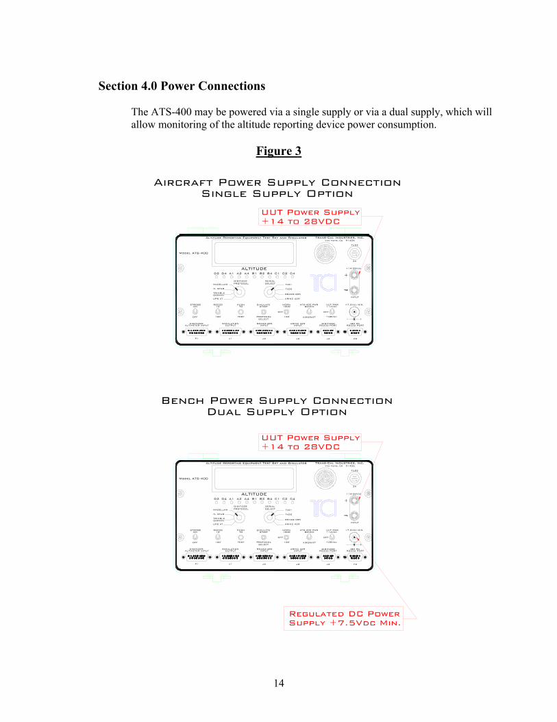
Section 4.0 Power Connections
The ATS-400 may be powered via a single supply or via a dual supply, which will allow monitoring of the altitude reporting device power consumption.
Figure 3
Regulated DC PowerSupply +7.5Vdc Min.
+28Vdc100'PROTOCOLTEST100'
SIMULATION
P1 J1
ALTIMETER INPUTDIGITIZER/
OUTPUT
OFF
J2 J3 J4
RS422/485INPUT
SELECT
DIGITIZERARINC 429INPUT RS232 PORT
AIRCRAFT
DIGITIZER SERIALPROTOCOL
PUSH
UPS AT
ON 10'RS232STROBE
TRIMBLEGARMIN
MAGELLAN
N. STAR
ARINC 429
1000'HORN
STARTTO
OFF
SIMULATEBENCH +14Vdc
OFF
ATS-400 PWR UUT PWR
TxD1
RS422/485
TxD2
SELECT
A2D2 D4 A1
Model ATS-400
B1A4 B2 C1B4 C2
ALTITUDEC4
P2
IBM PCRS232 PORT
+-
+7.5Vdc MIN.
INPUT
+
+14/28Vdc
2A
UUT Power Supply +14 to 28VDC
Trans-Cal Industries, Inc.Van Nuys, CA 91406
Altitude Reporting Equipment Test Set and Simulator
FUSE
IBM PCARINC 429RS422/485DIGITIZER/ SIMULATION DIGITIZER
P1
ALTIMETER INPUT
J1 J2
OUTPUT INPUT
J3 J4
INPUT RS232 PORT
P2
RS232 PORT
Van Nuys, CA 91406Trans-Cal Industries, Inc.
+14/28Vdc
+
+7.5Vdc MIN.
OFF
STROBEON
OFF
TEST100'SELECT
PROTOCOL
PUSHTO
RS23210'
SIMULATESTART
OFF
AIRCRAFT100' +28Vdc
ATS-400 PWRBENCH
HORN1000'
UUT PWR+14Vdc
N. STAR
UPS AT
TRIMBLEGARMIN
PROTOCOLDIGITIZER
MAGELLAN SELECTSERIAL
TxD2
RS422/485
ARINC 429
TxD1
Altitude Reporting Equipment Test Set and Simulator
Model ATS-400
C1
ALTITUDEA4A2A1D2 D4 B1 B2 B4 C2 C4
+-
INPUT
2A
FUSE
UUT Power Supply +14 to 28VDC
Aircraft Power Supply ConnectionSingle Supply Option
Bench Power Supply ConnectionDual Supply Option

15
Section 5.0 Front Panel Switch Functions
Strobe On-Off Toggle Switch On Applies ground to pin 6 of front panel connector P1. ICAO altitude data enable. Off Open circuit to pin 6 of front panel connector P1. ICAO altitude data disable.
RS232 10’-100’ Toggle Switch 10’ Applies ground to pin 2 of front panel connectors J2, J3, J4. Serial altitude data 10-
foot resolution enable output to digitizer. 100’ Open circuit to pin 2 of front panel connectors J2, J3, J4. Serial altitude data 100-
foot resolution enable output to digitizer.
Push-To-Test Pushbutton ON Test sequence of LED and alphanumeric display.
Simulate/Protocol Toggle Switch Simulate
Start Starts altitude encoder output simulation, See section 8.0.
Off Center off position. Protocol
Select Scrolls through ATS-400 serial data simulation output protocols see section 8.0.
Horn 1000’/100’ Toggle Switch 1000’ Horn sounds at 1000’ ICAO altitude code transitions. OFF Horn off. 100’ Horn sounds at 100’ ICAO altitude code transitions.
Aircraft/Bench Toggle Switch Bench ATS-400 Vdc power is isolated from Input Vdc for (UUT) unit under test. ATS-
400 power provided through 2.1mm front panel jack. Aircraft ATS-400 Vdc power is coupled to 5-Way binding post +14 to 28Vdc for (UUT)
unit under test.
UUT Power Toggle Switch +14 Vdc ATS-400 Power on. Input Vdc from binding post is directed to pin 14 of front
panel connectors P1 and J3. Off Center off position.
+28Vdc ATS-400 Power on. Input Vdc from binding post is directed to pin 8 of front panel connectors P1 and J3.
16
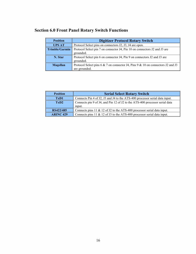
Section 6.0 Front Panel Rotary Switch Functions
Position Digitizer Protocol Rotary Switch UPS AT Protocol Select pins on connectors J2, J3, J4 are open.
Trimble/Garmin Protocol Select pin 7 on connector J4, Pin 10 on connectors J2 and J3 are grounded.
N. Star Protocol Select pin 6 on connector J4, Pin 9 on connectors J2 and J3 are grounded.
Magellan Protocol Select pins 6 & 7 on connector J4, Pins 9 & 10 on connectors J2 and J3 are grounded.
Position Serial Select Rotary Switch TxD1 Connects Pin 4 of J2, J3 and J4 to the ATS-400 processor serial data input. TxD2 Connects pin 9 of J4, and Pin 12 of J2 to the ATS-400 processor serial data
input. RS422/485 Connects pins 11 & 12 of J2 to the ATS-400 processor serial data input. ARINC 429 Connects pins 11 & 12 of J3 to the ATS-400 processor serial data input.

17
Section 7.0 Serial Interface Specifications
The following section details the serial data message formats and protocols currently accepted by the ATS-400. There is no accepted standard protocol for RS232 altitude data transmission. As a result, many avionics manufacturers developed unique protocols. Many of these different protocols are accepted by the ATS-400 and are detailed in this section. More formats and protocols may be added in the future as required.
7.1 General Characteristics of Serial Data Inputs
RS232 is an “unbalanced” serial communication format conforming to the EIA/TIA RS-232C standard. Logic levels typically seen on RS232 data lines are +9 (logic 0) and –9Vdc (logic 1). These voltages may drop to ±5Vdc at full load impedance of 3K ohms. All voltages are measured between signal and ground. Altitude reporting devices typically utilize asynchronous transmission in a simplex or talk only system. Baud rates, currently utilized by altitude reporting devices, range from 1200 to 9600 bps. The RS-232 standard specifies one transmitter and one receiver per RS232 port.
RS422 is a “balanced” two wire serial communication format conforming to the EIA/TIA RS-422 standard. Logic levels seen on RS422 data lines may range from +2 to +5Vdc (logic 0) and -2 to –5Vdc (logic 1). Driver load impedance is typically 100 ohms. All voltages are measured as signal A with respect to signal B. Altitude reporting devices typically utilize asynchronous transmission in a simplex or talk only system. Baud rates range from 1200 to 9600 bps. The RS-422 standard specifies one transmitter and seven receivers per two-wire data bus.
RS485 is a “balanced” two wire serial communication format conforming to the EIA/TIA RS-485 standard. Logic levels seen on RS485 data lines may range from +1.5 to +5Vdc (logic 0) and -1.5 to –5Vdc (logic 1). Driver load impedance is typically 54 ohms. All voltages are measured as signal A with respect to signal B. Altitude reporting devices typically utilize asynchronous transmission in a simplex or talk only system. Baud rates, currently utilized by altitude reporting devices, range from 1200 to 9600 bps. The RS-485 standard specifies one transmitter and thirty-two receivers per two-wire data bus.
18
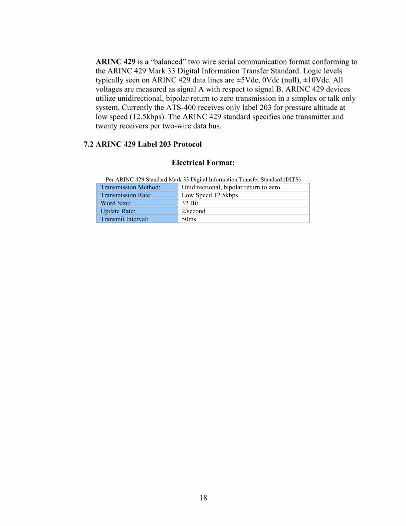
ARINC 429 is a “balanced” two wire serial communication format conforming to the ARINC 429 Mark 33 Digital Information Transfer Standard. Logic levels typically seen on ARINC 429 data lines are ±5Vdc, 0Vdc (null), ±10Vdc. All voltages are measured as signal A with respect to signal B. ARINC 429 devices utilize unidirectional, bipolar return to zero transmission in a simplex or talk only system. Currently the ATS-400 receives only label 203 for pressure altitude at low speed (12.5kbps). The ARINC 429 standard specifies one transmitter and twenty receivers per two-wire data bus.
7.2 ARINC 429 Label 203 Protocol
Electrical Format:
Per ARINC 429 Standard Mark 33 Digital Information Transfer Standard (DITS)
Transmission Method: Unidirectional, bipolar return to zero. Transmission Rate: Low Speed 12.5kbps Word Size: 32 Bit Update Rate: 2/second Transmit Interval: 50ms

19
Altitude Data Message:
Message Display Example:
ARINC429 LBL203 +001611
BIT FUNCTION CODING NOTES 1 Label 1st Digit 1 2 2 Label 1st Digit 0 3 Label 2nd Digit 0 0 4 Label 2nd Digit 0 5 Label 2nd Digit 0 6 Label 3rd Digit 0 3 7 Label 3rd Digit 1 8 Label 3rd Digit 1 9 Pad
10 Pad 11 Altitude Resolution 0 = 1 feet
1 = 100 feet
12 Altitude 1 ft. Altitude represented in 13 Altitude 2 ft. two’s complement 14 Altitude 4 ft. fractional binary 15 Altitude 8 ft. notation. 16 Altitude 16 ft. 17 Altitude 32 ft. (LSB = 1 ft.) 18 Altitude 64 ft. (Range = 131,072 ft.) 19 Altitude 128 ft. 20 Altitude 256 ft. 21 Altitude 512 ft. 22 Altitude 1024 ft. 23 Altitude 2048 ft. 24 Altitude 4096 ft. 25 Altitude 8192 ft. 26 Altitude 16384 ft. 27 Altitude 32768 ft. 28 Altitude 65536 ft. 29 Sign 30 SSM (MSB) Bit 30 & 31 SSM Definitions:
0 0 Failure 0 1 No Computed Data
31 SSM (LSB) 0 0 Functional Test 1 1 Normal Operation
32 Parity (Odd)
20
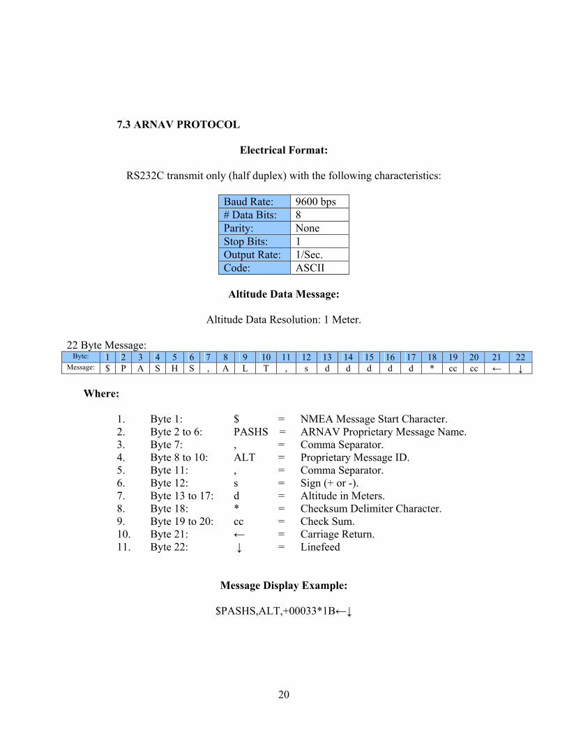
7.3 ARNAV PROTOCOL
Electrical Format:
RS232C transmit only (half duplex) with the following characteristics:
Baud Rate: 9600 bps # Data Bits: 8 Parity: None Stop Bits: 1 Output Rate: 1/Sec. Code: ASCII
Altitude Data Message:
Altitude Data Resolution: 1 Meter.
22 Byte Message:
Byte: 1 2 3 4 5 6 7 8 9 10 11 12 13 14 15 16 17 18 19 20 21 22 Message: $ P A S H S , A L T , s d d d d d * cc cc ← ↓
Where:
1. Byte 1: $ = NMEA Message Start Character. 2. Byte 2 to 6: PASHS = ARNAV Proprietary Message Name. 3. Byte 7: , = Comma Separator. 4. Byte 8 to 10: ALT = Proprietary Message ID. 5. Byte 11: , = Comma Separator. 6. Byte 12: s = Sign (+ or -). 7. Byte 13 to 17: d = Altitude in Meters. 8. Byte 18: * = Checksum Delimiter Character. 9. Byte 19 to 20: cc = Check Sum. 10. Byte 21: ← = Carriage Return. 11. Byte 22: ↓ = Linefeed
Message Display Example:
$PASHS,ALT,+00033*1B←↓

21
7.4 MAGELLAN PROTOCOL
Electrical Interface:
RS232C with the following characteristics:
Baud Rate: 1200 bps # Data Bits: 7 Parity: Even Stop Bits: 1 Output Rate: 1/Sec. Code: ASCII
Altitude Data Message:
Altitude Data Resolution: 100 ft. or 10 ft.
17 Byte Message:
Byte: 1 2 3 4 5 6 7 8 9 10 11 12 13 14 15 16 17 Message: $ M G L s d d d d d T s t t cc cc ←
Where:
1. Byte 1: $ = ASCII “$” 2. Byte 2: M = ASCII “M” 3. Byte 3: G = ASCII “G” 4. Byte 4: L = ASCII “L” 5. Byte 5: s = Sign (+ or -). 6. Byte 6 to 10: d = Altitude in feet, right justified, with leading zeros. 7. Byte 11: T = ASCII “T” 8. Byte 12 s = Sign (+ or -). 9. Byte 13 to 14 t = Sensor temperature in ºC. 10. Byte 15 to 16 cc = Check Sum 11. Byte 17 ← = Carriage Return.
Message Display Example:
$MGL+00050T+25D6←

22
7.5 NORTHSTAR PROTOCOL
Electrical Format:
RS232C transmit only (half duplex) with the following characteristics:
Baud Rate: 2400 bps # Data Bits: 8 Parity: None Stop Bits: 1 Output Rate: 1/Sec. Code: ASCII
Altitude Data Message:
Altitude Data Resolution: 100 ft. or 10 ft.
10 Byte Message:
Byte: 1 2 3 4 5 6 7 8 9 10 Message: A L T <Space> -/d d d d d ←
Where:
1. Byte 1: A = ASCII “A” 2. Byte 2: L = ASCII “L” 3. Byte 3: T = ASCII “T” 4. Byte 4: Space = ASCII Space 5. Byte 5: -/d = Negative Sign or altitude data. 6. Byte 6 to 9: d = Altitude in feet, right justified, with leading zeros. 7. Byte 10: ← = Carriage Return
Message Display Example:
ALT 00050←
Error/Status Messages:
The following error/status codes replace the altitude data as follows:
-02500 Encoder disabled.

23
7.6 SHADIN PROTOCOL
Electrical Interface:
RS232C transmit only (half duplex) with the following characteristics:
Baud Rate: 9600 bps # Data Bits: 8 Parity: None Stop Bits: 1 Output Rate: 1/Sec. Code: ASCII
Altitude Data Message:
Altitude Data Resolution 1 ft.
17 Byte Message: Byte: 1 2 3 4 5 6 7 8 9 10 11 12 13 14 15 16 17
Message: R M S <Space> s d d d d d T s t t cc cc ←
Where:
1. Byte 1: R = ASCII “R” 2. Byte 2: M = ASCII “M” 3. Byte 3: S = ASCII “S” 4. Byte 4: Space = ASCII Space 5. Byte 5: s = Sign (+ or -). 6. Byte 6 to 10: d = Altitude in feet, right justified, with leading zeros. 7. Byte 11: T = ASCII “T” 8. Byte 12 s = Sign (+ or -). 9. Byte 13 to 14 t = Sensor temperature in ºC. 10. Byte 15 to 16 cc = Check Sum 11. Byte 17 ← = Carriage Return.
Message Display Example:
RMS +00015T+551C←

24
7.7 TRIMBLE/GARMIN PROTOCOL
Electrical Format:
RS232C transmit only (half duplex) with the following characteristics:
Baud Rate: 9600 bps # Data Bits: 8 Parity: None Stop Bits: 1 Output Rate: 1/Sec. Code: ASCII
Altitude Data Message:
Altitude Data Resolution: 100 ft. or 10 ft.
10 Byte Message:
Byte: 1 2 3 4 5 6 7 8 9 10 Message: A L T <Space> -/d d d d d ←
Where:
1. Byte 1: A = ASCII “A” 2. Byte 2: L = ASCII “L” 3. Byte 3: T = ASCII “T” 4. Byte 4: Space = ASCII Space 5. Byte 5: -/d = Negative Sign or altitude data. 6. Byte 6 to 9: d = Altitude in feet, right justified, with leading zeros. 7. Byte 10: ← = Carriage Return
Message Display Example:
ALT 00050←
Error/Status Messages:
The following error/status codes replace the altitude data as follows:
-99900 Encoder disabled.

25
7.8 UPS AT PROTOCOL
Electrical Format:
RS232C transmit only (half duplex) with the following characteristics:
Baud Rate: 1200 bps # Data Bits: 8 Parity: None Stop Bits: 1 Output Rate: 1/Sec. Code: ASCII
Altitude Data Message:
Altitude Data Resolution: 100 ft. or 10 ft.
17 Byte Message: Byte: 1 2 3 4 5 6 7 8 9 10 11 12 13 14 15 16 17
Message: # A L <Space> s d d d d d T s t t cc cc ←
Where:
1. Byte 1: # = ASCII “#” 2. Byte 2: A = ASCII “A” 3. Byte 3: L = ASCII “L” 4. Byte 4: Space = ASCII Space 5. Byte 5: s = Sign (+ or -). 6. Byte 6 to 10: d = Altitude in feet, right justified, with leading zeros. 7. Byte 11: T = ASCII “T” 8. Byte 12 s = Sign (+ or -). 9. Byte 13 to 14 t = Sensor temperature in ºC. 10. Byte 15 to 16 cc = Check Sum 11. Byte 17 ← = Carriage Return.
Message Display Example:
#AL +00050T+25D6←
Error/Status Messages:
The following error/status codes replace the altitude data as follows:
-09980 Encoder heater not ready. -09981 Possible encoder hardware problem. -09982 Altitude out of range.

26
7.9 UPS AT LORAN 618 PROTOCOL
Electrical Format:
RS232C transmit only (half duplex) with the following characteristics:
Baud Rate: 1200 bps # Data Bits: 7 Parity: Odd Stop Bits: 1 Output Rate: 1/Sec. Code: ASCII
Altitude Data Message:
Altitude Data Resolution: 100 ft. or 10 ft.
17 Byte Message: Byte: 1 2 3 4 5 6 7 8 9 10 11 12 13 14 15 16 17
Message: # A L <Space> s d d d d d T s t t cc cc ←
Where:
1. Byte 1: # = ASCII “#” 2. Byte 2: A = ASCII “A” 3. Byte 3: L = ASCII “L” 4. Byte 4: Space = ASCII Space 5. Byte 5: s = Sign (+ or -). 6. Byte 6 to 10: d = Altitude in feet, right justified, with leading zeros. 7. Byte 11: T = ASCII “T” 8. Byte 12 s = Sign (+ or -). 9. Byte 13 to 14 t = Sensor temperature in ºC. 10. Byte 15 to 16 cc = Check Sum 11. Byte 17 ← = Carriage Return.
Message Display Example:
#AL +00050T+25D6←
Error/Status Messages:
The following error/status codes replace the altitude data as follows:
-09980 Encoder heater not ready. -09981 Possible encoder hardware problem. -09982 Altitude out of range.

27
7.10 Serial Data Matrix
Protocol Baud R
ate
Data B
its
Parity
Stop Bits
Flow C
ntl.
Byte 1
Byte 2
Byte 3
Byte 4
Byte 5
Byte 6
Byte 7
Byte 8
Byte 9
Byte 10
Byte 11
Byte 12
Byte 13
Byte 14
Byte 15
Byte 16
Byte 17
Byte 18
Byte 19
Byte 20
Byte 21
Byte 22
Trimble/ Garmin/ Icarus
9600
8 N 1 N A L T Spa c e
d -
d d d d ←
Northstar 2400
8 N 1 N A L T Spa c e
d -
d d d d ←
UPS AT 1200
8 N 1 N # A L Spa c e
± d d d d d T ± T e m p ºC
T e m p ºC
Chk.s um
Chk.s um
←
UPS AT 618
LORAN
1200
7 O 1 N # A L Spa c e
± d d d d d T ± T e m p ºC
T e m p ºC
Chk.s um
Chk.s um
←
Magellan 1200
7 E 1 N $ M G L ± d d d d d T ± T e m p ºC
T e m p ºC
Chk.s um
Chk.s um
←
Shadin 9600
8 N 1 N R M S Spa c e
± d d d d d T ± T e m p ºC
T e m p ºC
Chk.s um
Chk.s um
←
ARNAV 9600
8 N 1 N $ P A S H S , A L T , ± d d d d d * Chk.s um
Chk.s um
← ↓

28
Section 8.0 Simulation Mode
The ATS-400 will simulate the output of altitude reporting devices in both ICAO parallel and serial RS232 formats. This function is controlled by the SIMULATE START/PROTOCOL SELECT toggle switch. The ICAO parallel code is provided on connector J1 labeled SIMULATION OUTPUT. The RS232 data is provided on pin 13 of connector J2, labeled RS422/485.
Parallel ICAO Simulation:
1. Prior to entering the simulate mode, disconnect any digitizer which may input data to the
ATS-400.
2. Connect a transponder, GPS, MFD or other device to either the ICAO parallel simulation output connector J1. Following is a wiring example using the UPS AT SL-20 transponder.
3. Apply power to the transponder and switch the ATS-400 UUT power switch to the on
position.
4. Switch the transponder to ALT mode.
5. Push the Simulate Start switch up once. The ATS-400 will begin transmitting the ICAO altitude code at a rate of 6000 feet per minute beginning at –1100 feet. To hold an altitude, push the Simulate Start switch up once. To increase the rate of climb to 30,000 feet per minute push the Simulate Start button twice. To descend, push the Simulate Start button down.

29
Wiring connection using serial data (RS232) interface. Note! UPS AT Protocol must be selected with protocol toggle switch on the ATS-400.
ATS-400 Connector J2
UPS AT SL70 Rear Connector
Pin Function Pin 13 TxD 4 1 Serial Ground 3
ATS-400 Conn. J1
UPS AT SL-20 Transponder
Rear Connector Pin Function Pin 1 D4 35 2 A1 13 3 A2 31 4 A4 12 5 B1 33 6 Signal Common
Connect to ground to enable.
No connection.
7 D2 No connection. No connection. Transponder Vdc
input. 1
9 B2 14 10 B4 32 11 C1 16 12 C4 15 13 C2 34
No connection. Transponder Vdc input.
1
15 Ground 2

30
Wiring Harness Diagram for the ATS-400 Test Set g gPC 9 Pin Serial Cable
SSD120 Encoder 9 Pin to ATS-400 (J4) Digitizer RS232 Port
ATS-400Connector (P2)"IBM PC RS232 PORT"
IBM PC Serial Comunications Port
ATS-400Connector (J4)"DIGITIZER RS232 PORT"
SSD120 Encoder 15 Pin to ATS-400 (P1) Digitizer Altimeter Input
SSD120 Altitude EncoderRS232 PORT
ATS-400 Connector (P1)"DIGITIZER ALTIMETER INPUT"
SSD12015 PinD-Subminiature Connector
IBM PC 9 Pin Serial Communication to ATS-400 (P2) Serial RS232
Encoder 9 Pin Cable
Encoder 15 Pin Cable

31
©2004 Trans-Cal Industries, Inc.
16141 Cohasset Street Van Nuys, CA 91406-2908
(818)787-1221 * (800)423-2913 * (818)787-8916FAX www.trans-cal.com