Embed Size (px)
Citation preview
Trane Horizon™
Absorption Series
Two-Stage Steam-Fired or Hot Water
Absorption Water Chillers
380-1650 Tons – 50-60 Hz
Built for Industrial and Commercial Applications
ABS-PRC004-ENJanuary 2001
ABS-PRC004-EN©American Standard Inc. 2001
Introduction
History of Trane Absorption Chillers
Trane has been the leader in absorption chiller design and manufacturing for 40years. Dedicated to the advancement of absorption chiller technology, Trane is theonly North American chiller manufacturer to commercialize double effect absorptionover 25 years ago. Since then, Trane has manufactured and shipped over 10,000absorbers to commercial, industrial and process applications worldwide. Innovationssuch as microelectronic controls, adaptive frequency drives and smart purge systemshave modernized the technology, making it more capable, more reliable and in manyapplications, more economical.
3ABS-PRC004-EN
Contents
Better By Design
In the early 1990’s, with the assistance ofthe Gas Research Institute, Trane begandevelopment of an advanced series ofabsorption chiller designs. The newdesign was expected to redefine theindustry standards for overall systemperformance, efficiency and reliability.
In 1995, Trane announced the Horizon™
line of steam/hot water absorptionchillers. True to its name and true to thehigh standards for its design, the TraneHorizon chiller offers system advantagesthat go beyond that of other absorptionchillers currently on the market.
• Produces chilled water to as low as40 F (+4.4 C).
• Unlike other absorbers, Horizon chillersapply to tower water flow as low as3.6 gpm/ton.
• Start-up capability with tower watertemperatures as low as 45 F.
• Can operate with tower watertemperatures as low as 55 F.
• Includes factory installed crossoverpipe, lithium bromide filter, and steamvalve as standard.
• Pumps designed for 50,000 life hours.• Key components made of stainless
steel or CuNi.• Marine water boxes on cooling water
connections.• Design special capability.
Introduction
Features and BenefitsComponent Identification, Typical Two-StageSteam Illustration, Refrigerant Cycle Overview
Application ConsiderationsOperating Limits, Sound, Water Flow/Treatment,Combination Systems, Multiple Machines
Selection ProcedureComputer Selection Procedure,Model Number Description
Performance DataCapacity/COP/Steam Rate/Flow Rate, Pressure DropTables, Percent Energy Input vs. Percent Capacity atNominal Conditions Graph, Maximum Capacity Graph,Part Load Graph, Pressure Drop vs. Flow Rate Graph,Flow Rate Limitations
Electrical Data
Controls Data
Dimensions and WeightsPhysical Dimensions, Weights, Connection Sizes,Refrigerant Charging, Separated Machine Sections,Foundation Support, Rigging/Service Clearances,Chiller Isolation, Insulation Lengths
Jobsite ConnectionsTypical Piping
Mechanical Specifications
Standard Features/Options/Design Special Options
Standard Conversion Table
2
4
8
9
12
16
18
20
34
38
41
43
ABS-PRC004-EN4
Features andBenefits General
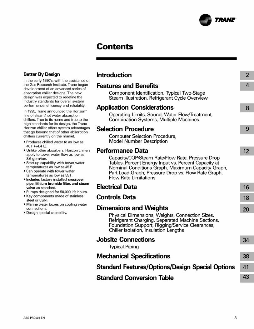
Better By DesignFrom the outside most chilled watersystems may look comparable, yet ifone understands the differences, thebenefit of the Horizon™ chiller becomesapparent. The Trane Horizon design seta new performance standard fortoday’s absorption chillers, earning areputation as a viable alternative totoday’s electric powered chiller.
UCP2™ Intelligent ControlsChiller controls are key to optimalchiller performance. Like the TraneCenTraVac™ centrifugal water chiller,the Horizon absorption chiller line usesUCP2 control panel intelligence for thehighest performance possible
ISO9001 Quality CertifiedManufacturing/Testing FacilityThe engineering, manufacturing andmarketing of the Horizon product line,are administered in La Crosse, WIunder the strict discipline of ISOQuality System Certification.
Energy Efficient For Life Cycle CostSavingsThe UCP2 “reverse series cycle” canbe as much as 5-15 percent moreefficient at full load than other cycles.
Chilled water temperatures as low as40 F allows for lower systemcomponent costs and reducedoperating costs.
Fully Automatic Purge SystemTrane’s new purge system removesnon-condensables from the machinecontinuously and automatically whilelogging purge information through theUCP2. This helps prevent damage tothe chiller while maintaining the peakperformance.
Automatic, Energy EfficientCrystallization ProtectionCrystallization – the solidifying of therefrigerant/ lithium bromide solutioninto salt crystals – occurs whentemperature margins are notmaintained during chiller operation.The Horizon chiller accurately controlsthe solution during chiller operation,while at the same time adjusting theenergy input for optimum energyefficiency.
UCP2 Sensing, Detecting, and Recovery(SDR) SafetyThe SDR safety is an automaticcorrective action process that provides asecondary line of defense againstcrystallization. If cycle temperaturepoints become close to the point ofcrystallization, SDR executes a recoverycycle that in worst cases, will shut downthe machine safely.
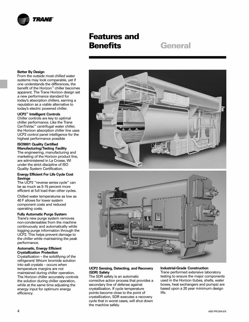
Industrial-Grade ConstructionTrane performed extensive laboratorytesting to ensure the major componentsused in the Horizon (tubes, shells, waterboxes, heat exchangers and pumps) arebased upon a 20 year minimum designlife.

5ABS-PRC004-EN
Features andBenefits General
Factory Installed Crossover PipeIncluded As StandardThe Horizon chiller has a number ofavailable features that can save chillerowners thousands of dollars in installedcosts. For example, unlike otherabsorption chiller manufacturers, Traneincludes as standard on the Horizon, thecooling water cross over pipe betweenthe absorber and condenser. This savescustomers the additional cost of acrossover pipe and the added cost forinstalling it at the job site.
Modular, Break Apart OptionFor Easier InstallationFor easy access into buildings withlimited space, the Horizon can be orderedin a two or three-piece modular designfor easy disassembly and reassembly ofthe modules at the job site.
Dedicated SupportProfessional engineering expertise isavailable from Trane at local sales officesworldwide. Trane headquartersapplications and engineering field officesupport gives you access torefrigeration, air conditioning and facilitycontrol system applications.
Designed With Easy Servicing in MindRemovable spray trees, individuallyreplaceable tubes, marine stylewaterboxes are a few of the Horizonchiller features that can be appreciatedwhen chiller maintenance is performed.To further assist in this area, Trane alsooffers service training for the chillermaintenance staff and/or local postwarranty service from trainedtechnicians and extended warranty plansthat can be customized for specificwarranty related needs.
Environmentally FriendlyThe Trane Horizon™ two-stage steamabsorption chillers contain no CFC’smaking them completely ozone friendly.Nonhazardous lithium molybdate isused as the corrosion inhibitor forHorizon chillers, further enhancing itspositive influence for the preservation ofthe environment.
Controls DataControl integration with Tracer™ chillerplant system controllers with a singletwisted-wire pair cable. UCP2 controlincludes these features/benefits:• Proportional Integral Derivative (PID)
control strategies for increasedoperating stability and optimal chilledwater temperature accuracy.
• Adaptive Control™ for keeping thechiller “on line” and safe.
• Microprocessor based safeties forpump motor protection, lowrefrigerant water temperature cutout,low leaving water temperature cutoutand high interstage pressure cutout.
• Clear language interface in multipledifferent languages
• Standard and custom reports• Over 200 diagnostics• Cost-effective adaptation to system
upgrades• Compatible with Trane Integrated
Comfort™ systems (ICS)

ABS-PRC004-EN6
ComponentIdentification
Features andBenefits
Horizon™ Two-Stage Fired or Hot Water Absorption Water Chiller Component Identification
High Temp Generator
Low TempGeneratorSpray Tree
High TempGenerator(Separable)
CondensateOutletControl
CondensateHeat
Exchanger
CondenserTube Access
Cover
MistEliminators
Steam Inlet Valve
EvaporatorSpray Tree
AbsorberSpray Tree
Fixed andFloating Tube
Supports
Low TempLiBr HX
High TempLiBr HX
SolutionFloat Valve
PurifierPurge
AdjustableFrequency
Drive
Unit ControlPanel (UCP)
ABS/CNDCrossover
VacuumPump
EvaporatorSpray Pump
AbsorberSpray Pump
(AFD)
PurgeEductor Low Temp
GeneratorPump (AFD)
RefrigerantStorage Tank
Absorber TubeAccess Cover
Evaporator
SeparableShells
GeneratorInter-StageConnection
Condenser
Low TempGenerator
(Plate Type)

7ABS-PRC004-EN
RefrigerationCycle
Features andBenefits
Figure FB-1 – Absorption Refrigeration CycleAbsorption Refrigeration CycleFigure FB-1 is an example of typicalmachine operation at a standard ratingpoint condition (i.e., 85° tower, 44°leaving chilled water) at full load. Dilutesolution is a relatively high refrigerantcontent and low lithium bromidecontent. An intermediate solution is amixture of dilute and concentratedsolutions. A concentrated solution is onewith a relatively low refrigerant contentand high lithium bromide content.
High Temperature Generator (1)Solution (intermediate) enters thebottom of the high temperaturegenerator where the refrigerant watervapor is separated from the solution viathe energy source inside the tube bundle(steam or hot water). The refrigerantvapor travels to the low temperaturegenerator. The now concentratedsolution returns to the absorber throughthe high and low temperature heatexchangers.
Solution 300 F (149 C), Refrigerant Vapor300 F (149 C), Tube Bundle 115 PSIGsteam or 346 F (174 C)
Low Temperature Generator (2)Solution (dilute) is pumped into the lowtemperature generator where thesolution is boiled creating additionalrefrigerant vapor via the refrigerantvapor inside the tube bundle. Therefrigerant vapor then condenses andflows to the condenser. The nowintermediate solution then flows to oneof two locations: the absorber spraysystem to mix with strong concentratedsolution from the high temperaturegenerator or to the high temperaturegenerator.
Solution 180 F (82 C), Vapor 190 F (88 C)
Condenser (3)Refrigerant vapor (produced by the lowtemperature generator) and refrigerantliquid (via the tube bundle) enter thecondenser to be reduced in pressure/temperature via expansion device fordelivery to the evaporator. The heat ofcondensation is rejected to the coolingwater inside the tube bundle.
Refrigerant 100 F (38 C), Entering/Leaving Cooling Water 93 F/97 F(34 C/36 C)
Evaporator (4)System water runs through the tubebundle where its heat is transferred tothe refrigerant causing the refrigerant tovaporize/boil. The refrigerant vapor flowsto the slightly lower pressure in theabsorber.
Entering/Leaving System Water 54 F/44 F(12 C/7 C), Evaporator Pump Refrigerant42 F (6 C)
Absorber (5)Refrigerant vapor is absorbed by thelithium bromide solution (dilute) to becirculated and cycled again. The solutionis pumped to the low temperaturegenerator. Heat (acquired in theevaporator) is rejected via the coolingwater inside the tube bundle.
Leaving Solution 95 F (35 C), Entering /Leaving Cooling Water 85 F/93 F(29 C/34 C)
Absorption Process (6)Solution (concentrated) enters the spraysystem from the high and lowtemperature generators enters the spraysystem wetting the tubes and providing
a liquid surface for the refrigerant vaporfrom the evaporator to absorb into thelithium bromide solution. The solutiontemperature/concentration sprayed inthe absorber controls the absorberpressure thereby controlling theevaporator refrigerant temperature.
Entering Solution 112 F (44 C)
Low, High and Condensate HeatExchangers (7)Solution flows through the high and lowtemperature heat exchangers to bepreheated reducing the heat energyrequired to induce boiling within thegenerators and to decrease thetemperature of the solution beingreturned to the absorber, thusdecreasing the load on the coolingtower.
(1)
(2) (3)
(4)
(5)
(6)(7)

ABS-PRC004-EN8
ApplicationConsiderations General
GeneralThe Horizon two-stage steam-fired or hotwater absorption chiller is designed toprovide 40 F to 60 F (+4.4 C - +15.6 C)chilled water for comfort or processcooling applications within all threemarket segments – commercial,industrial and institutional. The primaryadvantage of the absorption chiller overother chiller options, is its ability to usesteam or hot water to provide energy-saving cooling.
Operating LimitsTrane two-stage absorption chillersoperate with nominal 120 PSIG steam ornominal 370 F hot water. In allapplications, superheat should belimited so steam temperature does notexceed 400 F. Hot water machines canuse up to 370 F hot water.
Water flows within the limits indicatedon the appropriate selection charts willinsure tube water velocities notexceeding 10 feet per second in coppertubes and 11 feet per second incupronickel tubes. Changes in condenserwater temperature should not exceed 1-degree F per minute between the rangeof 75 -95 F.
Sound and VibrationAbsorption units are well suited for areaswhere low sound levels are required.The Trane Horizon two-stage steamabsorption chiller will operate undernormal load conditions at less than an85 dBA sound pressure level. Duringoperation there is no vibration of anycomponents that could be damaging tothe chiller or could transmitobjectionable sound or vibration to thebuilding.
Chiller InstallationThe following should be taken intoconsideration when installing anabsorption chiller:• Rigging and service clearances• Foundation support• Chiller isolation for sound/vibration
reduction• Condensate handling• Steam supply control• Condenser water temperature control• Chilled water flow control• Chilled and condenser water flow limit• Generator hot water application
Cooling Tower Water FlowThe ARI standard gpm/ton forabsorption chillers is 4.0 but lower flowthrough the condenser and absorbersection will present an opportunity for asmaller tower and smaller condenserpump. By designing a system aroundlower flows there will likely be significantannual chiller plant electrical energysavings. For more information on lowerflows on the cooling tower water circuitrefer to the appropriate engineeringbulletin.
Water TreatmentThe use of untreated or improperlytreated water may result in scaling,erosion, and corrosion, algae or slime.It is recommended that the services of aqualified water treatment specialist beused to determine what treatment, if anyis advisable. The Trane Companyassumes no responsibility for the resultsof untreated, or improperly treatedwater.
Combination SystemsPeak energy savings can be achievedwhen using a combination of electricchillers and absorption chillers for airconditioning loads. The absorptionchiller is used to shave seasonal billablepeak power demands during summeroperation, and the electric chiller is runbelow the allowed demand limit,reducing costly demand charges.Trane offers both electric chillers andabsorption chillers with the unit controlpanel (UCP2) as standard. Although the
chillers have different features andmodes of operation, the chiller controlpanel looks and acts the same across allchiller lines. Each control panel isprogrammed to monitor the particularchiller for which it was designed butmaintenance and service personnelneed only become familiar with onecontrol panel. Combined with a TraneTracer™ system a chiller plant has almostunlimited operational flexibility and allequipment is supplied from a singlesource.
Multiple MachinesThe Trane absorption machine can beapplied to series or parallel chilled waterflow depending upon the designrequirement. Accurate chilled watertemperatures can be maintained onindividual machines between 100percent and 10 percent chiller load whichallows for a wide range of controloptions. Each chiller has a stand-alonecontrol system to manage the desiredwater temperature and also the ability toreceive remote commands to supportvarious system demands from a controlcenter. This versatility of control makesthe management of more than onemachine relatively easy.
Parallel flow allows minimum chilledwater pressure drop through themachines. However, with one machine“off,” it is not usually possible tomaintain the design chilled watertemperature unless one machine isvalved-off and the chilled water flowdecreased.
Series flow permits design chilled watertemperature at light loads with onemachine “off.” However, at all operatingconditions, the chilled water pressuredrop through the machine is high.
A decision concerning whicharrangement is best for an individualsystem should be based on an analysisof system water and temperature riserequirements, system and machinepressure drop characteristics, andinstallation cost.

9ABS-PRC004-EN
SelectionProcedure
Selection ProcedureAbsorption refrigeration machines areusually selected to provide the requiredrefrigeration capacity with the smallestpractical machine of sufficient size.Machine size is based on chilled-waterflow rates and temperatures specified forthe air side of the system.
Total air-conditioning system first costcan be minimized by a careful analysis ofsystem operating parameters. The effectof flow rates and temperatures, on boththe building air side and the refrigerationmachine selections, should beinvestigated to determine which systemrepresents the best investment for theowner.
The information on the following pagesprovides performance data, at ARIstandard conditions, for capacity in tons,efficiency, flow rates and water pressuredrops. All capacities are in accordancewith ARI 560 Standard revision, and arebased on fouling factors of .0001 for theevaporator waterside tubing and .00025for the absorber and condenser tubing.
Standard FoulingUnit performance at non-standardfouling factors may vary from standardperformance. Fouling factors estimatethe heat transfer penalty that coincideswith the effect of typical fouling inevaporator and absorber/condenser(cooling) water circuits. All selectionsshould use the standard fouling factor tomore accurately estimate the chillerperformance in an equipment room andto comply with ARI 560.
ARI Standard Fouling FactorsEvaporator Condenser/Absorber
English Units – hr-ft2-F/Btu
0.0001 0.00025SI Units – m2-K/kW
0.018 0.044
Final SelectionA final selection must be done by thelocal Trane sales engineer using theTrane Horizon™ Absorption SelectionProgram. For applications higher than1600 feet [500 meters] above sea level,final selection requires review byAbsorption Product Marketing. Prior toaccessing the computer selectionprogram, the following data inputsshould be tabulated:• Temperature or pressure of the hot
water or steam• Two of the following three values must
be provided1:– Evaporator Delta-T– Evaporator Flow– Cooling Capacity
• Leaving-Evaporator WaterTemperature
• Entering-Absorber Water Temperature• Cooling Water Flow• Chilled water and tower water fouling
factors
Other options that may also be selectedare:• Type and thickness of tube material• Type of solution flowing through the
evaporator and tower loop2.1 Any limitations or restrictions shouldalso be given (i.e., pressure drop, gpm,etc.).
2 Absorption chillers can be selected witha wide variety of media other thanwater (evaporator and absorber/condenser, or both). For media otherthan water, contact the local Trane salesoffice for chiller selections andinformation.
Additional FoulingAny selection that uses a fouling factorgreater than 0.0001 for the evaporatortubes, and 0.00025 for the condenser/absorber tubes, is a more conservativeestimate that should only be used ifthere is an abnormal amount of foulingcontaminants in the water systems. TheARI 560 Standard defines “additionalfouling” as “Conditions such as waterhardness, organic material, suspendedsolids and/or water velocity maynecessitate the use of a greater fieldfouling allowance than that provided inthe Standard Rating of equipment.” TheTrane two-stage Horizon Selectionprogram should be used to determinethe effect of nonstandard fouling factors.The following guidelines can be used forestimation prior to the selection:
ARI Standard Fouling Factors ForAdditional Fouling
Evaporator Condenser/AbsorberEnglish Units – hr-ft2-F/Btu
0.0002 0.00026 – 0.00075SI Units – m2-K/kW
0.035 0.046 – 0.1320
Part Load PerformanceHorizon™ absorption chillers exhibitexcellent part-load performancecharacteristics. Air conditioning systemloads are usually significantly less thanfull-load design conditions. Therefore,the absorption chiller operates at fullload a small percentage of the time. Part-load absorption chiller operation isnormally associated with reduced tower-water temperatures. At part-loadoperation, the heat rejected to thecooling tower is less than at full-loadoperation. Also, part-load operation istypically associated with reduced outsidewet-bulb temperatures, resulting inimproved cooling tower performance.The net result of less heat rejection andlower wet-bulb temperature is coolertower water entering the chiller andimproved unit performance.

ABS-PRC004-EN10
SelectionProcedure
Model NumberDescription
SelectionProduct Coding DescriptionThe coding block precisely identifies allcharacteristics of a any Horizon™ Two-StageSteam-Fired or Hot Water Absorption Chiller.
Table S-1 — Product Coding DescriptionMODL - Absorption Unit ModelABTF Horizon Two-StageDSEQ - Unit Design SequenceE0 Design SequenceNTON - Unit Nominal Tonnage380 380 Tons440 440 Tons500 500 Tons575 575 Tons660 660 Tons750 750 Tons850 850 Tons950 950 Tons1050 1050 Tons1150 1150 Tons1200 1200 Tons1350 1350 Tons1500 1500 Tons1650 1650 TonsVOLT - Unit Voltage190 190/50/3200 200/60/3220 220/50/3230 230/60/3380 380/50/3415 415/50/3460 460/60/3575 575/60/3ENSR - Unit Energy SourceHOTW Hot WaterSTM SteamENPR - Unit Energy Pressure115 115 Psig Steam400 400 Psig Hot WaterPVCN - Pressure Vessel ConstructionASME ASME Evp-Abs-CdsISPL Ispesl Evp-Abs-CdsLMIN Les-Mines Evp-Abs-CdsTUV Tuv Evp-Abs-CdsSTD StandardLGTM - Low-Temp Generator Tube Material/
SurfaceSB01 .028 Wall 95-5 CuNi SmoothSB04 .028 Wall 90-10 CuNi SmoothSB05 .035 Wall 90-10 CuNi SmoothSB06 .049 Wall 90-10 CuNi SmoothHGTM -High-Temp Generator Tube Material/
SurfaceSB16 .028 Wall 409 Sstl Smooth
EVTM - Evaporator Tube Material/SurfaceES01 .028 Wall 95-5 CuNi EnhancedES11 .025 Wall 90-10 CuNi EnhancedES05 .035 Wall 90-10 CuNi EnhancedES09 .028 Wall Copper EnhancedES12 .025 Wall Copper EnhancedCDTM - Condenser Tube MaterialSB04 .028 Wall 90-10 CuNi SmoothSB05 .035 Wall 90-10 CuNi SmoothSB06 .049 Wall 90-10 CuNi SmoothSB09 .028 Wall Copper SmoothSB10 .035 Wall Copper SmoothABTM - Absorber Tube Material/SurfaceSB00 .022 Wall 95-5 CuNi SmoothSB01 .028 Wall 95-5 CuNi SmoothSB02 .035 Wall 95-5 CuNi SmoothSB03 .049 Wall 95-5 CuNi SmoothSB04 .028 Wall 90-10 CuNi SmoothSB05 .035 Wall 90-10 CuNi SmoothSB06 .049 Wall 90-10 CuNi SmoothGNWA - Generator Water Box ArrangementGN02 1-Pass 150 PSI Non-Marine RF FlangeGN04 2-Pass 150 PSI Non-Marine RF FlangeCAWA - Condenser and Absorber Water Box
ArrangementCA01 1-Pass Cond, 2-Pass Abs 150 PSI
Marine VictaulicCA02 1-Pass Cond, 2-Pass Abs 150 PSI
Marine RF FlangeCA05 2-Pass Cond, 2-Pass Abs 150 PSI
Marine VictaulicCA06 2-Pass Cond, 2-Pass Abs 150 PSI
Marine RF FlangeEVWA - Evaporator Water Box ArrangementEV01 2-Pass 150 Psi Non-Marine VictaulicEV02 2-Pass 150 Psi Non-Marine RF FlangeCAWC - Condenser and Absorber Water
ConnectionsLELE In LH End - Out LH EndLERE In LH End - Out RH EndRERE In RH End - Out RH EndEVWC - Evaporator Water ConnectionsLEBK Inlet Connection Left BackLEFR Inlet Connection Left FrontREBK Inlet Connection Right BackREFR Inlet Connection Right FrontLEND Inlet LH EndREND Inlet RH EndCAFT - Condenser and Absorber Water Box
Fluid TypeWTR WaterEGLY Ethylene Glycol SolutionPGLY Propylene Glycol SolutionEVFT - Evaporator Water Box Fluid TypeWTR WaterEGLY Ethylene Glycol SolutionPGLY Propylene Glycol Solution

11ABS-PRC004-EN
SelectionProcedure
EVLV - Unit Energy ValveVB01 2-Way 2.00" 150# Wafer V-BallVB02 2-Way 3.00" 150# Wafer V-BallVB03 2-Way 4.00" 150# Wafer V-BallVB11 2-Way 2.00" 300# Wafer V-BallVB12 2-Way 3.00" 300# Wafer V-BallVB13 2-Way 4.00" 300# Wafer V-BallVB14 2-Way 6.00" 300# Wafer V-BallVB41 2-Way 2.00" 150# Flanged V-BallVB42 2-Way 3.00" 150# Flanged V-BallVB43 2-Way 4.00" 150# Flanged V-BallVB44 2-Way 6.00" 150# Flanged V-BallEVIN - Unit Energy Valve InstallationFLD Field InstalledFACT Factory InstalledUPNT - Unit PaintSFPT Standard Factory PaintEVPN - Evaporator Pan ConstructionSTD Steel evaporator panSSTL Stainless steel evap panWCNM - Water Chiller NameplateSNMP Standard Plastic NameplateBNMP Decorative Brass NameplateSPKG - Unit Shipping PackageDAU Domestic - Assembled UnitDDU Domestic - 3 Pc Disassembled UnitDDG Domestic - 2 Pc Disassembled UnitDAUF Domestic - Assembled - 3 Pc Field
DisassemblyDAGF Domestic - Assembled - 2 Pc Field
DisassemblyEAU Export - Assembled UnitEDU Export - 3 Pc Disassembled UnitEDG Export - 2 Pc Disassembled UnitEAUF Export - Assembled - 3 Pc Field
DisassemblyEAGF Export - Assembled - 2 Pc Field
DisassemblyELPP - Electrical Protection PackageSELP StandardPPCO - Control Panel Power ConnectionCB Circuit BreakerFDS Fused Disconnect SwitchNFDS Non-Fused Disconnect SwitchTB Terminal BlockLCLD - Local Clear Language DisplayCLDC Complex CharacterCLDO StandardTRIM - Tracer Interface Control ModuleTRMI Tracer 100 (COM3)TRMS Tracer Summit™ (COM4)PRIM - Printer Interface Control ModuleYES Printer Interface ModuleACWR - Ambient Chilled Water ResetYES Ambient Chilled Water Reset
WVUO - Under/Over Phase VoltageProtection
YES Under-Over Voltage ProtectionCTWF - Chilled/Tower Water Flow DisplayYES Differential Water Pressure
TransducersOPTM - Options Control ModuleYES Options ModuleFLSW - Flow Switches2FS1 150 PSI NEMA 1 Switch Qty 23FS1 150 PSI NEMA 1 Switch Qty 32FS2 300 PSI NEMA 1 Switch Qty 23FS2 300 PSI NEMA 1 Switch Qty 32FS3 150 PSI NEMA 4X Switch Qty 23FS3 150 PSI NEMA 4X Switch Qty 32FS4 300 PSI NEMA 4X Switch Qty 23FS4 300 PSI NEMA 4X Switch Qty 31FS1 150 PSI NEMA 1 Switch Qty 11FS2 300 PSI NEMA 1 Switch Qty 11FS3 150 PSI NEMA 4X Switch Qty 11FS4 300 PSI NEMA 4X Switch Qty 1LBMF - Lithium Bromide FilterYES Lithium Bromide FilterSOPT - Special Unit OptionsSpecial Unit Options As Defined On SalesOrder Basis. Contact Sales Order Group ForCurrent ListingUINS - Unit InsulationHINS Hot Unit Insulation OnlyCINS Cold Unit InsulationHCIN Hot and Cold Unit InsulationUNIT - Parts Warranty - Whole UnitM2 Two MonthsM4 Four MonthsM6 Six MonthsM8 Eight MonthsY2 Second YearY3 Second Thru Third YearY4 Second Thru Fourth YearY5 Second Thru Fifth YearLB01 - Labor Warranty - First YearY1 First YearLB02 - Labor Warranty - Beyond First YearY2 Second Year OnlyY3 Second Thru Third YearY4 Second Thru Fourth YearY5 Second Thru Fifth YearBRM1 - Bromide Warranty - First YearY1 First YearBRM2 - Bromide Warranty - Beyond First
YearY2 Second Year OnlyY3 Second Thru Third YearY4 Second Thru Fourth YearY5 Second Thru Fifth Year
Model NumberDescription

ABS-PRC004-EN12
PerformanceData
Table PD-1 — Performance Data at ARI ConditionsEnglish Units*
Coefficient Steam Chilled Water Cond/Abs WaterCapacity of Rate Flow Rate Press. Drop Flow Rate Pr. Drop
Model (Tons) Performance (lbm/ton/hr) (gpm) (ft Wtr) (gpm) (ft Wtr)ABTF-380 360 1.21 9.73 861 13.7 1520 26.5ABTF-440 426 1.21 9.69 1018 14.6 1760 30.5ABTF-500 493 1.22 9.65 1178 15.6 2000 34.9ABTF-575 558 1.21 9.65 1333 26.9 2300 19.4ABTF-660 659 1.22 9.62 1576 29.1 2640 20.9ABTF-750 765 1.22 9.63 1833 31.6 3000 22.9ABTF-850 915 1.24 9.51 2187 13.7 3400 13.3ABTF-950 1030 1.24 9.51 2462 19.1 3800 17.5ABTF-1050 1145 1.24 9.49 2736 25.8 4200 22.5ABTF-1150 1259 1.24 9.48 3010 33.9 4600 28.3ABTF-1200 1264 1.19 9.83 3022 13.2 4800 16.0ABTF-1350 1419 1.19 9.84 3391 18.2 5400 21.2ABTF-1500 1573 1.19 9.84 3759 24.4 6000 27.2ABTF-1650 1721 1.20 9.77 4113 31.7 6600 34.1
SI Units**Coefficient Steam Chilled Water Cond/Abs Water
Capacity of Rate Flow Rate Press. Drop Flow Rate Pr. DropModel (kW) Performance (kg/kw-hr) (m3/hr) (m wg) (m3/hr) (m wg)
ABTF-380 1266 1.20 1.25 196 4.5 345 8.7ABTF-440 1498 1.21 1.25 231 4.8 400 10.0ABTF-500 1734 1.21 1.24 268 5.1 454 11.5ABTF-575 1963 1.21 1.24 303 8.8 522 6.4ABTF-660 2318 1.22 1.24 358 9.5 600 6.9ABTF-750 2691 1.21 1.24 416 10.4 681 7.5ABTF-850 3218 1.23 1.23 497 4.5 772 4.4ABTF-950 3623 1.23 1.23 559 6.3 863 5.7ABTF-1050 4027 1.24 1.22 621 8.5 954 7.4ABTF-1150 4428 1.24 1.22 684 11.1 1045 9.3ABTF-1200 4446 1.19 1.27 686 4.3 1090 5.2ABTF-1350 4991 1.19 1.27 770 6.0 1226 7.0ABTF-1500 5533 1.19 1.27 854 8.0 1363 8.9ABTF-1650 6053 1.20 1.26 934 10.4 1499 11.2*English:4.0 gpm/nominal ton, Pstm = 120 psig, TctwS = 85 F, TcwS = 44 F, TcwR = 54 F, 0.0001 Evaporator fouling and 0.00025Absorber/Condenser fouling.
**Metric:.26 m3/kWh, Pstm = 120 psig, TctwS = 29.44 C, TcwS = 6.67 C, TcwR =12.2 C, 0.0001 Evaporator fouling and 0.00025 Absorber/Condenser fouling.

13ABS-PRC004-EN
PerformanceData
Table PD-2 — Performance Data at Trane Rated ConditionsEnglish Units*
Coefficient Steam Chilled Water Cond/Abs WaterCapacity of Rate Flow Rate Press. Drop Flow Rate Pr. Drop
Model (Tons) Performance (lbm/ton/hr) (gpm) (ft Wtr) (gpm) (ft Wtr)ABTF-380 334 1.18 9.98 665 8.2 1368 21.7ABTF-440 395 1.18 9.93 787 8.7 1584 25.0ABTF-500 457 1.19 9.9 909 9.3 1800 28.5ABTF-575 517 1.19 9.9 1029 15.7 2070 16.0ABTF-660 611 1.19 9.86 1216 16.9 2376 17.2ABTF-750 710 1.19 9.88 1413 18.3 2700 18.8ABTF-850 843 1.21 9.76 1679 7.9 3060 11.0ABTF-950 951 1.21 9.74 1893 11.0 3420 14.5ABTF-1050 1058 1.21 9.73 2106 14.9 3780 18.6ABTF-1150 1165 1.21 9.71 2319 19.6 4140 23.4ABTF-1200 1167 1.16 10.09 2324 7.6 4320 13.2ABTF-1350 1311 1.16 10.09 2611 10.5 4860 17.4ABTF-1500 1455 1.16 10.09 2897 14.1 5400 22.4ABTF-1650 1595 1.17 10.01 3175 18.4 5940 28.1
SI Units**Coefficient Steam Chilled Water Cond/Abs Water
Capacity of Rate Flow Rate Press. Drop Flow Rate Pr. DropModel (kW) Performance (kg/kw-hr) (m3/hr) (m wg) (m3/hr) (m wg)
ABTF-380 1175 1.17 1.29 151 2.7 311 7.1ABTF-440 1389 1.18 1.28 179 2.9 360 8.2ABTF-500 1607 1.18 1.28 206 3.1 409 9.4ABTF-575 1819 1.18 1.28 234 5.2 470 5.2ABTF-660 2149 1.19 1.27 276 5.5 540 5.6ABTF-750 2497 1.19 1.27 321 6.0 613 6.2ABTF-850 2965 1.20 1.26 381 2.6 695 3.6ABTF-950 3345 1.20 1.26 430 3.6 777 4.8ABTF-1050 3721 1.21 1.25 478 4.9 858 6.1ABTF-1150 4098 1.21 1.25 527 6.4 940 7.7ABTF-1200 4105 1.16 1.30 528 2.5 981 4.3ABTF-1350 4611 1.16 1.30 593 3.4 1104 5.7ABTF-1500 5118 1.16 1.30 658 4.6 1226 7.3ABTF-1650 5610 1.17 1.29 721 6.0 1349 9.2*English:4.0 gpm/nominal ton, Pstm = 120 psig, TctwS = 85 F, TcwS = 44 F, TcwR = 54 F, 0.0001 Evaporator fouling and 0.00025Absorber/Condenser fouling.
**Metric:.26 m3/kWh, Pstm = 120 psig, TctwS = 29.44 C, TcwS = 6.67 C, TcwR =12.2 C, 0.0001 Evaporator fouling and 0.00025 Absorber/Condenser fouling.

ABS-PRC004-EN14
PerformanceData
Figure PD-1 – ABTF Capacity vs. Chilled Water Supply Temperature at Various Cooling WaterSupply Temperatures
Figure PD-2 – ABTF Part Load Performance – Energy Input vs. Capacity at Various CoolingWater Supply Temperatures – Chilled Water Supply Temperature = 44 F

15ABS-PRC004-EN
Figure PD-4 – Pressure Drop vs. Chilled Water Flow Rate – English and SI Units
Figure PD-3 – Pressure Drop vs. Cooling Water Flow Rate – English and SI Units
PerformanceData
Pressure Drop vs.Water Flow Rate
ABS-PRC004-EN16
ElectricalData
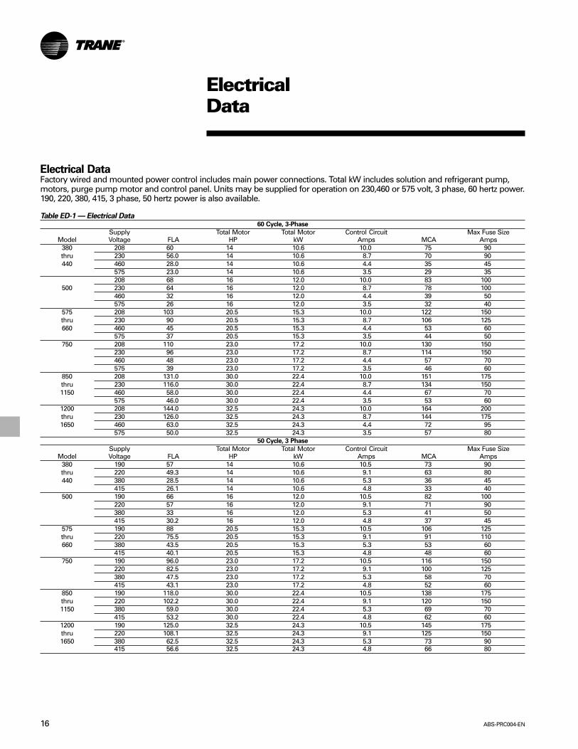
Electrical DataFactory wired and mounted power control includes main power connections. Total kW includes solution and refrigerant pump,motors, purge pump motor and control panel. Units may be supplied for operation on 230,460 or 575 volt, 3 phase, 60 hertz power.190, 220, 380, 415, 3 phase, 50 hertz power is also available.
Table ED-1 — Electrical Data60 Cycle, 3-Phase
Supply Total Motor Total Motor Control Circuit Max Fuse SizeModel Voltage FLA HP kW Amps MCA Amps
380 208 60 14 10.6 10.0 75 90thru 230 56.0 14 10.6 8.7 70 90440 460 28.0 14 10.6 4.4 35 45
575 23.0 14 10.6 3.5 29 35208 68 16 12.0 10.0 83 100
500 230 64 16 12.0 8.7 78 100460 32 16 12.0 4.4 39 50575 26 16 12.0 3.5 32 40
575 208 103 20.5 15.3 10.0 122 150thru 230 90 20.5 15.3 8.7 106 125660 460 45 20.5 15.3 4.4 53 60
575 37 20.5 15.3 3.5 44 50750 208 110 23.0 17.2 10.0 130 150
230 96 23.0 17.2 8.7 114 150460 48 23.0 17.2 4.4 57 70575 39 23.0 17.2 3.5 46 60
850 208 131.0 30.0 22.4 10.0 151 175thru 230 116.0 30.0 22.4 8.7 134 1501150 460 58.0 30.0 22.4 4.4 67 70
575 46.0 30.0 22.4 3.5 53 601200 208 144.0 32.5 24.3 10.0 164 200thru 230 126.0 32.5 24.3 8.7 144 1751650 460 63.0 32.5 24.3 4.4 72 95
575 50.0 32.5 24.3 3.5 57 8050 Cycle, 3 Phase
Supply Total Motor Total Motor Control Circuit Max Fuse SizeModel Voltage FLA HP kW Amps MCA Amps
380 190 57 14 10.6 10.5 73 90thru 220 49.3 14 10.6 9.1 63 80440 380 28.5 14 10.6 5.3 36 45
415 26.1 14 10.6 4.8 33 40500 190 66 16 12.0 10.5 82 100
220 57 16 12.0 9.1 71 90380 33 16 12.0 5.3 41 50415 30.2 16 12.0 4.8 37 45
575 190 88 20.5 15.3 10.5 106 125thru 220 75.5 20.5 15.3 9.1 91 110660 380 43.5 20.5 15.3 5.3 53 60
415 40.1 20.5 15.3 4.8 48 60750 190 96.0 23.0 17.2 10.5 116 150
220 82.5 23.0 17.2 9.1 100 125380 47.5 23.0 17.2 5.3 58 70415 43.1 23.0 17.2 4.8 52 60
850 190 118.0 30.0 22.4 10.5 138 175thru 220 102.2 30.0 22.4 9.1 120 1501150 380 59.0 30.0 22.4 5.3 69 70
415 53.2 30.0 22.4 4.8 62 601200 190 125.0 32.5 24.3 10.5 145 175thru 220 108.1 32.5 24.3 9.1 125 1501650 380 62.5 32.5 24.3 5.3 73 90
415 56.6 32.5 24.3 4.8 66 80

17ABS-PRC004-EN
ElectricalData Wiring
OptionalExternal Auto Stop Switch
With Auto Reset After Closure
OptionalEmergency Stop Switch
Requires Manual Reset After Reclosure
OptionalOutdoor Air Temperature Sensor
For Ambient-Based Chilled Water Reset(Furnished by Trane - Field Installed)
OptionalEnergy Valve
Monitor Output; 2-10 VDC(Requires Options Module)
OptionalTracer Temperature SensorOrdered with Tracer Panel(Requires Options Module)
OptionalEvaporator External Chilled Water
Setpoint Input; 2-10 VDC or 4-20 MA(Requires Options Module)
OptionalBi-Directional Communication Link
To Tracer Panel, If Present(Requires Tracer Communication Module)
OptionalBi-Directional Communication Link To
Additional UCP2 Control Panel(s).If Present
(Requires Tracer Communication Module)
OptionalBi-Directional Communication LinkTo Remote Clear Language Display
Panel, If Present(Requires IPC Buffer Module)
OptionalCommunication Link to Printer,
If Present9-Pin Sub-D RS-232 Connector
(Requires Printer Module)
RequiredChilled Water Flow Switch
RequiredCondenser-Absorber Water Flow Switch
RequiredCondenser-Absorber Water Pump Relay
RecommendedChilled Water Pump Relay
OptionalHot Water Pump
OptionalMachine Manual Reset
Alarm Status Relay
OptionalMachine Automatic Reset
Alarm Status Relay
OptionalLimit Warning Status Relay
OptionalPurge Alarm Indicator Light
OptionalInterstage Pressure Relief
Request Status Relay(Requires Options Module)
OptionalMaximum Capacity Status Relay
(Requires Options Module)
OptionalTracer Controlled Relay
(Requires Options Module)
OptionalTower Temperature Low Relay
(Requires Options Module)
11
10
13
13
13
13
13
13
13
6 8
6 8
4 12
7 8
4 12
4 12
7 8
4 12
4
4 12
12
4
124
124
124
124
GENERAL NOTES:
THIS DRAWING IS TO BE USED FOR THE PURPOSE OF ESTIMATING FIELD WIRING REQUIREMENTS CHECK SALES ORDERTO DETERMINE WHICH OPTIONS ARE SPECIFIED AND REFER TO FIELD CONNECTION WIRING DIAGRAM FOR ACTUAL FIELDWIRING REQUIRED. DASHED LINES INDICATE DEVICES AND FIELD WIRING SUPPLIED BY CUSTOMER.
ALL FIELD WIRING MUST BE IN ACCORDANCE WITH THE NATIONAL ELECTRIC CODE OR STATE AND LOCALREQUIREMENTS WHICH APPLY. ALL CUSTOMER CONTROL CIRCUIT WIRING MUST HAVE A MINIMUM RATING OF150 VOLTS.
DO NOT ROUTE LOW VOLTAGE (30 VDC MAXIMUM) WIRING IN THE SAME CONDUIT AS CONTROL VOLTAGE(115 VAC) WIRING AND DO NOT POWER-UP UNIT UNTIL CHECK-OUT AND START-UP PROCEDURES HAVE BEENCOMPLETED.
THE MAIN UNIT CONTROL PANEL PROVIDES A CONTACT CLOSURE TO CONTROL THE INDICATED CUSTOMER CONNECTEDDEVICE. CUSTOMER TO PROVIDE 115 VAC POWER TO EACH DEVICE. MAXIMUM FUSE SIZE IS15 AMPS.
REQUIRED WIRING NOTES:
TRANE PROVIDES A TERMINAL BLOCK, FUSED OR NON-FUSED DISCONNECT SWITCH OR A CIRCUIT BREAKER IN THEMAIN UNIT CONTROL PANEL FOR LINE VOLTAGE CONNECTION WHICH REQUIRES THE USE OF COPPER CONDUCTORSONLY CHECK SALES ORDER TO DETERMINE WHICH OPTION IS SPECIFIED. WIRING SIZED PER NATIONAL ELECTRIC CODEBASED ON NAMEPLATE MINIMUM CIRCUIT AMPACITY RATING.
EVAPORATOR, CONDENSER AND FLOW SWITCHES ARE TO BE INSTALLED AND WIRED TO THE MAIN UNIT CONTROLPANEL BY THE INSTALLING CONTRACTOR. THE PURCHASE OF FLOW SWITCHES FROM TRANE IS OPTIONAL. EACH FLOWSWITCH CIRCUIT REQUIRES TWO WIRES. 115 VAC. MINIMUM CONTACT RATING AT115 VAC IS 4.8 MA.
CHILLED AND CONDENSER-ABSORBER WATER FLOW MUST BE PROVEN PRIOR TO CHILLER OPERATION CONDENSER-ABSORBER WATER PUMP MUST BE CONTROLLED BY THE MAIN UNIT CONTROL PANEL FOR CHILLER SAFETY.
CIRCUIT REQUIRES TWO WIRES. 115 VAC. MAXIMUM MODULE CONTACT RATING AT 115 VAC OR 30 VDC IS2.88 AMPS INDUCTIVE. 1/3 HP.
OPTIONAL WIRING NOTES:
OPTIONAL CONTROL FOR A CUSTOMER SPECIFIED OR INSTALLED LATCHING TRIPOUT. THE CHILLER WILL RUN NORMALLYWHEN THE CONTACT IS CLOSED AND TRIP THE CHILLER OFF WITH A MANUALLY RESETTABLE DIAGNOSTIC WHEN THECONTACT OPENS. MANUAL RESET IS ACCOMPLISHED WITH THE DIAGNOSTIC KEY ON THE FRONT OF THE MAIN UNITCONTROL PANEL. CUSTOMER SUPPLIED SILVER CONTACTS ARE REQUIRED FOR 24 VDC. 12 MA RESISTIVE LOAD. CIRCUITREQUIRES TWO WIRES, 30 VDC MAXIMUM. DO NOT ROUTE IN CONDUIT WITH HIGHER VOLTAGE CIRCUITS.
OPTIONAL CONTROL FOR A CUSTOMER SPECIFIED OR INSTALLED REMOTE AUTO-STOP FUNCTION. THE CHILLER WILLRUN NORMALLY WHEN THE CONTACT IS CLOSED AND STOP THE CHILLER WHEN THE CONTACT OPENS. RECLOSURE OFTHE CONTACT WILL PERMIT THE CHILLER TO AUTOMATICALLY RETURN TO NORMAL OPERATION. CUSTOMER SUPPLIEDSILVER CONTACTS ARE REQUIRED FOR 24 VDC. 12 MA RESISTIVE LOAD. CIRCUIT REQUIRES TWO WIRES, 30 VDCMAXIMUM. DO NOT ROUTE IN CONDUIT WITH HIGHER VOLTAGE CIRCUITS.
CIRCUIT REQUIRES TWO WIRES, 115 VAC. NORMALLY OPEN MAXIMUM MODULE CONTACT RATING AT 115 VAC OR 30 VDCIS 2.88 AMPS INDUCTIVE. 1/3 HP
CIRCUIT REQUIRES SHIELDED WIRE PAIR, 30 VDC MAXIMUM BELDON TYPE 8760 RECOMMENDED. MAXIMUM LENGTH OF5000 FEET.
OPTIONAL REMOTE CLEAR LANGUAGE DISPLAY PANEL REQUIRES SEPARATE CUSTOMER PROVIDED 24 VAC POWERSOURCE.
3
4
5
6
7
8
10
11
12
13
14
1
2
�����CAUTIONUSE COPPER CONDUCTORS ONLY!
UNIT TERMINALS ARE NOT
DESIGNED TO ACCEPT OTHER TYPESOF CONDUCTORS.
FAILURE TO DO SO MAY CAUSEDAMAGE TO THE EQUIPMENT.
!�����WARNINGHAZARDOUS VOLTAGE!
DISCONNECT ALL ELECTRIC POWERINCLUDING REMOTE DISCONNECTSBEFORE SERVICING.
FAILURE TO DISCONNECT POWERBEFORE SERVICING CAN CAUSESEVERAL PERSONAL INJURY ORDEATH.
! �����AVERTISSEMENTVOLTAGE HASARDEUX!DECONNECTEZ TOUTES LES SOURCESELECTIRQUES INCLUANT LES DISJONCTEURSSITUES A DISTANCE AVANT D’EFFECTUERL’ENTRETIEN.
FAUTE DE DECONNECTER LA SOURCEELECTRIQUE AVANT D’EFFECTUER L’ENTRETIENPEUT ENTRAINER DES BLESSURESCORPORELLES SEVERES OU LA WORT.
!
RequiredChilled Water
Pump
EvaporatorIn
(RH or LH)
Tower WaterInlet
RequiredCondenser-Absorber
Water Pump FRONT ELEVATION
MainUnit
ControlPanel
Required Chilled Water Flow Switch
Required Condenser-Absorber Water Flow Switch
115 Vac 15A Provided by Customer 3
Line Voltage(See Unit Nameplate)
56
6
14
Low Voltage (30 VDC Maximum) 3
ABS-PRC004-EN18
Controls Data
Setting The StandardsTrane set the standard for unitmicroprocessor controls in 1985 with thefirst generation of UCP. Associated withthis standard have been:• Proportional Integral Derivative (PID)
control strategies which provide stableoperation and high accuracy for betterperformance along with feed forwardplus.
• Adaptive Control™ to keep the chiller“on line” and at the same time keepthe chiller away from a major failure;
• Software based safeties that do notdepend on electromechanicalhardware – hardware that meansquestionable reliability and added cost;
• Operator interface that accesses chillerinformation and control adjustments atthe front of the panel.
Trane Now Offers UCP2™
UCP2 adds more flexibility, morereliability and better system performancethan even our most demandingcustomers expect.
FlexibilityTrane offers the ability to adapt tochanges easily and effectively withoutadding prohibitive cost. To provideflexibility, the controller responds to awide variety of needs for:
• System Designs including equipment,operating conditions, and controlsvariations that are either existing orbeing considered for new installations.
Key to designing non-traditionalsystems is the ability to evaluate thecost and reliability issues of thesesystems in comparison to the moretraditional systems. Trane recommendsthe use of C.D.S. Network EquipmentEconomics, the Trane ApplicationsManuals, and consultation with a Tranesales engineer for help in this analysis.
• System Upgrades including the abilityto accommodate changes in the chilledwater system design or equipmentroom requirements or toaccommodate new technologies thatbecome available.
Flexibility
• Modular structure or the UCP2 makes itpossible for the designer to select thesystem controls and associatedinterfaces to Tracer™ (or other buildingautomation systems) that are requiredfor the chiller plant design. With thismodular concept, capability can beadded or upgraded at any time — withonly temporary interruption of chilledwater production.
• The operator can quickly program aCustom Report — so that only what isconsidered to be the most frequentlyaccessed/important reports areavailable — at any time, right at thefront of the panel.
• With easy front panel programmabilityof Daily, Service Start-up and MachineConfiguration settings and setpoints,the operator, serviceman, and systemdesigner can customize the use of themicro controller to unique conditions ofthe chiller plant — whether the purposeof chilled water is for comfort coolingor for process cooling.
• All data that is necessary for the safeoperation and easy serviceability of thechiller is provided as standard on allHorizon™ absorption chillers. Optionsare available that provide additionalcontrols/data that are required for: anindustrial/process system design,applications outside of the typicalchilled water system design, the needfor redundant machine protection, orthe desire for more systeminformation.
ReliabilityTo most people, reliability means“dependable — giving the same resulton successive trials.” However, to ourcustomers it has come to mean “keepchilled water flowing.” In other words,“when I turn the switch on — cold watercomes out.” In order to do this, the microcontroller must be aware of what ishappening in the system. But moreimportantly, it must be able to makedecisions and adjustments to keep thechiller running as long as possible evenwhen non-standard conditions exist.Conditions such as bad power or badwater (flow, temperature, fouling) orsystem component failure. Also the
Trane UCP2 panel continuously monitorsfor noncondensables and purgesautomatically.• With Enhanced Adaptive Control™ the
controller does everything it can toavoid taking the chiller off line.— Senses potential overload, freeze
and condenser overpressureconditions
— Displays a warning message aboutthe potential condition/safety trip
— Take the following corrective actionsequentially as the conditionworsens:- limits loading- prevents further loading- unloads until condition improves- takes chiller off line
• With more diagnostics and diagnostichistory that are time/date stamped andwith help messages, the operator orserviceman can take faster and moreeffective corrective action.
System Performance“Chilled Water System” encompassesmany levels of control: StandaloneChiller, Chiller Plant, Applied System,Central Building Automation System.However, regardless of the system levelbeing design, the unit controls becomecritical not just in making every leveloperate reliably but in facilitating optimalperformance. UCP2 provides morecapability and more intelligence to makethis operation/optimization possible.
Panel Features:The absorption chiller Unit Control Panel(UCP2) incorporates the followingfeatures and components:
Control Functions
• Smart dilution cycle duration based onsystem requirements
• Adaptive evaporator leaving fluidtemperature control
• Low evaporator temperature limit• High solution temperature limit• Solution flow control via AFD• Softloading• Nuisance trip prevention via Adaptive
Control• Chilled water reset• Optimum concentration control• Crystallization recovery via SDR• High temperature generator pressure
limit

19ABS-PRC004-EN
Controls Data
Safeties
• Smart shutdown sequence condenser/absorber loss of flow
• Low condenser/absorber watertemperature
• High interstage pressure limit• High pressure cutout• Evaporator leaving fluid temperature
cutout• Motor current overload• High motor winding temperature• Over/under voltage (optional)• Purge limit• Sensor failure detection
Monitored PointsChiller information is available at theoperator interface via a clear languagedisplay. Access to the information isthrough four dedicated report keys:Customer, Chiller, Cycle and Pump/Purge.
Customer ReportUser defined custom report (operatormay choose up to 20 points — from a listof over 100 choices).
Chiller ReportStatus, fluid temperatures, and setpoints:• Operating mode (i.e. run status)• Chilled water setpoint• Evaporator entering/leaving water
temperatures• Absorber entering/leaving water
temperatures• Condenser leaving water temperature
outdoor air temperature• Evaporator leaving water temperature• Chilled water reset
Cycle ReportRefrigerant temperatures and pressures:• Solution temperature leaving high
temperature generator• Interstage vapor temperature• Solution temperature entering level
control• Mixed solution temperature entering
low temperature heat exchanger• Solution temperature entering high
temperature generator• Interstage vapor pressure• High temperature generator leaving
concentration• Low temperature generator leaving
concentration• High temperature generator cutout and
monitor temperature• Crystallization detection temperature
• Crystallization trip temperature• Solution temperature leaving low
temperature generator• Saturated condenser refrigerant
temperature• Absorber entering concentration• LiBr crystallization margin• Solution temperature leaving absorber• Absorber spray temperature• Solution temperature leaving absorber• Solution temperature entering low
temperature generator• Saturated evaporator refrigerant
temperature• Evaporator leaving water temperature• Evaporator entering water temperature• Absorber entering water temperature• Absorber leaving water temperature• Condenser leaving water temperature• Solution pump auto/manual speed
command• Energy input auto/manual/slaved
reported command• Steam Supply Pressure• Generator Steam Pressure
Pump/Purge Report
• Solution pump— Starts and hours counters— Motor phase currents— Motor phase voltages (optional)
• Purge Pump— Operating mode and status— Refrigerant suction temperature— Pumpout rate— Total pumpout time— Service log
DiagnosticsThe absorption chiller Unit Control Panel(UCP2) provides over 70 active andhistoric diagnostics such as:• Water and refrigerant/solution
temperatures out of range• Solution pressures out of range• Loss of system water flows• Sensor and switch faults• Overload trips• Over/under voltage (optional)• Crystallization recovery• High pressure cutout• Emergency stop• Loss of communication to other
modules• Motor abnormal
Operator InterfaceThe Trane Horizon™ steam-firedabsorption chiller control panel, UCP2, iseasy to use, understand, accessinformation, read, change setpoints,diagnose problems, maintain, and toreset after shutdown.
ConvenienceEnunciation of all information is at thefront panel display (including power,voltage, amps, purge pressures, andnumber of starts data). Messagesdisplayed using clear language.
Readability
• Two line, 40 character display that iseasy to read from within a 60 degreeangle
• LCD backlight so that the display canbe read in a variety of equipment roomlighting
• Seven languages available• Metric (SI) units available• Complete character human interface
available
Remote Operator InterfaceWith the addition of an optional remoteinterface panel, up to four chillers withUCP2 can be monitored and controlled.All data available at each chiller’s localoperator interface is available to theremote operator interface via a singletwisted pair.
Ease of Use
• Keypad programmability — no manualswitches or setpoint potentiometers
• Logically arranged report groups withreport header and setpoint groups
• Selectable security• Variable points updated every two
seconds• Messages that direct user to problem
source via a menu item
Trane ICS CompatibilityThe Trane Absorption chiller controlpanel, UCP2, is 100 percent compatiblewith the Trane Integrated Comfort™
systems, ICS, UCP2 easily integrates intothe Tracer™ family of flexible chiller plantsystem controllers with a single twisted-wire pair communications cable.
For more information on the Traneabsorption chiller unit control panel,please contact your local Trane salesengineer.

ABS-PRC004-EN20
Dimensionsand Weights
PhysicalDimensions
ABTF-380, 440, 500Customer Notes:1. Front of unit is determined by facing
unit control panel2. All vertical dimensions include 5/16”
(7.99 mm) thick isolation pads.3. Dimensions shown are calculated
values.4. Evaporator, condenser, and absorber
water connections are for 8” (203mm) pipe. Available with 150#grooved connection for use withstyle 77 Victaulic coupling. Also,available with 150# AmericanStandard raised face flange (flangebolt holes straddle verticalcenterline).
5. High temperature generator steaminlet connection is for 2” (55 mm)pipe. Provided with 150# Americanraised face flange (flange bolt holesstraddle vertical centerline).
6. All water box vents are 1/4” (6 mm)NPT and drains are 3/4” (19 mm) NPT.
7. Flexible connection must be used forattachment to rupture disk. Do notapply more than 12 PSI internalpressure on machine withoutremoving rupture disc. Pipe rupturedisc to floor vent or to the outside tomeet local code.
8. Field piping must be arranged andsupported to avoid stress on theequipment. It is stronglyrecommended that the pipingcontractor refrain from pre-pipingcloser than 36” (914 mm) minimumto the equipment. This will allow forproper connection upon arrival of theunit at the job site. Necessaryadjustments can be made at thattime.
Right End
Left End
All catalog dimensional drawings are subjectto change. Current submittal drawingsshould be referred to for detaileddimensional information. Contact the localTrane sales office for submittal and templateinformation.

21ABS-PRC004-EN
Dimensionsand Weights
PhysicalDimensions
ABTF-380, 440, 500
Front
Back
Table DW-1 – English to SI UnitsCross Reference
Conversion Chart(Ft. to mm)
English Units SI Units3/8" 102 3/4" 705 1/4" 13311 1/4" 2861' 1 5/8” 3461' 7 3/8" 4921' 8" 5081' 8 7/8" 5302' 8 1/4" 8192' 115/8" 9033' 1" 9403' 4 1/2" 10223' 5 7/8" 10643' 6" 10673' 7 1/8" 10954' 6" 13724' 9" 14485' 1 1/2" 15625' 4 1/8" 16295' 8 3/4" 17496' 6 5/8" 19977' 2 5/8" 22007' 9 5/8" 23788' 7/8" 24618' 6 3/8" 26009' 5 7/8" 28929' 6 7/8" 291812' 2 3/4" 372713' 6" 411517' 10 1/4" 544217' 11 1/2" 547421' 4 7/8" 6525
ABS-PRC004-EN22
Dimensionsand Weights
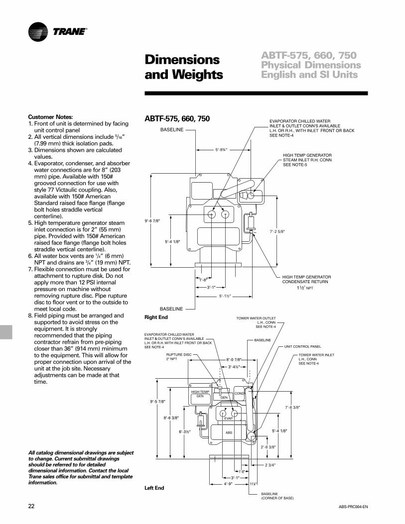
ABTF-575, 660, 750
Right End
Left End
Customer Notes:1. Front of unit is determined by facing
unit control panel2. All vertical dimensions include 5/16”
(7.99 mm) thick isolation pads.3. Dimensions shown are calculated
values.4. Evaporator, condenser, and absorber
water connections are for 8” (203mm) pipe. Available with 150#grooved connection for use withstyle 77 Victaulic coupling. Also,available with 150# AmericanStandard raised face flange (flangebolt holes straddle verticalcenterline).
5. High temperature generator steaminlet connection is for 2” (55 mm)pipe. Provided with 150# Americanraised face flange (flange bolt holesstraddle vertical centerline).
6. All water box vents are 1/4” (6 mm)NPT and drains are 3/4” (19 mm) NPT.
7. Flexible connection must be used forattachment to rupture disk. Do notapply more than 12 PSI internalpressure on machine withoutremoving rupture disc. Pipe rupturedisc to floor vent or to the outside tomeet local code.
8. Field piping must be arranged andsupported to avoid stress on theequipment. It is stronglyrecommended that the pipingcontractor refrain from pre-pipingcloser than 36” (914 mm) minimumto the equipment. This will allow forproper connection upon arrival of theunit at the job site. Necessaryadjustments can be made at thattime.
ABTF-575, 660, 750Physical DimensionsEnglish and SI Units
All catalog dimensional drawings are subjectto change. Current submittal drawingsshould be referred to for detaileddimensional information. Contact the localTrane sales office for submittal and templateinformation.

23ABS-PRC004-EN
Dimensionsand Weights
Front
Back
ABTF-575, 660, 750Table DW-2 – English to SI UnitsCross Reference
Conversion Chart(Ft. to mm)
English Units SI Units3/4" 192 3/4" 705 1/4" 1337" 17811 1/4" 2861' 1 5/8" 3461’ 3 7/8" 4061’ 7 3/8" 4921' 8" 5082' 6102' 6 7/8" 7842' 8 3/8" 8223' 1" 9403' 4 1/2" 10223' 5 7/8" 10643' 6" 10673' 7 1/8" 10964' 6" 13724' 9" 14485' 1 1/2" 15625' 4 1/8" 16295' 8 3/4" 17496' 3 1/2" 19187' 2 5/8" 22007' 8 3/8" 23468' 7/8" 24618' 6 3/8" 26009' 5 7/8" 28929' 6 7/8" 291820' 3" 617221' 3 1/2" 648826' 10 3/4" 819827' 823030' 7 3/8" 9330
ABTF-575, 660, 750Physical DimensionsEnglish and SI Units

ABS-PRC004-EN24
ABTF-850, 950, 1050, 1150
Dimensionsand Weights
Right End
Left End
Customer Notes:1. Front of unit is determined by facing
unit control panel2. All vertical dimensions include 5/16”
(8 mm) thick isolation pads.3. Dimensions shown are calculated
values.4. Evaporator and absorber connections
are for 12” (305 mm) pipe. Availablewith 150# (10 kg/cm2) groovedconnection for use with style 77Victaulic coupling. Also, available with150# American Standard raised faceflange (flange bolt holes straddlevertical centerline).
5. High temperature generator steaminlet connection is for 2” (55 mm)pipe. Provided with 150# Americanraised face flange (flange bolt holesstraddle vertical centerline).Condensate return connection is for1½" NPS. Both connections are to bewelded.
6. All water box vents are 1/4” (6 mm)NPT and drains are 3/4” (19 mm) NPT.
7. Flexible connection must be used forattachment to rupture disk. Do notapply more than 12 PSI (.8 kg/cm2)internal pressure on machine withoutremoving rupture disc. Pipe rupturedisc to floor vent or to the outside tomeet local code.
8. Field piping must be arranged andsupported to avoid stress on theequipment. It is stronglyrecommended that the pipingcontractor refrain from pre-pipingcloser than 36” (914 mm) minimumto the equipment. This will allow forproper connection upon arrival of theunit at the job site. Necessaryadjustments can be made at thattime.
ABTF-850,950,1050,1150Physical DimensionsEnglish and SI Units
All catalog dimensional drawings are subjectto change. Current submittal drawingsshould be referred to for detaileddimensional information. Contact the localTrane sales office for submittal and templateinformation.

25ABS-PRC004-EN
Dimensionsand Weights
ABTF-850, 950, 1050, 1150
Front
Back
Table DW-3 – ABTF 850-1150 DimensionsEnglish Units
MachineSize AA BB DD GG KK850 23’-10¼” 20’ 20’-3¼” 10’-3¼” 14’-10”950 25’-10¼” 22' 22’-3¼” 12’-3¼” 16’-10”1050 27’-10¼” 24' 24’-3¼” 14’-3¼” 18’-10”1150 29’-10¼” 26' 26’-3¼” 16’-3¼” 20’-10”
SI Units
MachineSize AA BB DD GG KK850 7271 6096 6179 3131 4521950 7880 6706 6788 3741 51311050 8490 7315 7398 4350 57401150 9100 7925 8007 4959 6350
Table DW-4 – English to SI UnitsCross Reference
Conversion Chart(Ft. to mm)
English Units SI Units
3 1/4" 839" 2299 1/4" 2359 5/8" 2441' 3 1/8" 3841' 9 7/8" 5561' 11" 5841' 11 5/8" 6002' 2 1/8" 6642' 2 5/8" 6753' 1 1/2" 9533' 4 3/8" 10263' 6" 10673' 9 7/8" 11654' 5" 13464' 6" 13724' 9" 14484' 11 1/8" 15025' 10 1/2" 17916' 18296' 4 1/8" 19346' 9 5/8" 20737' 8 3/4" 23567' 10 1/2" 24009' 1 7/8" 279110' 2 1/4" 310510’ 3 1/4" 313110' 9 1/8" 328011' 9 5/8" 359711' 10 5/8" 362312’ 3 1/4" 374114’ 3 1/4" 435016’ 3 1/4" 495923' 10 1/4" 727125’ 10 1/4" 788027’ 10 1/4" 849020’ 10 1/4" 9100
ABTF-850,950,1050,1150Physical DimensionsEnglish and SI Units
ABS-PRC004-EN26
Dimensionsand Weights
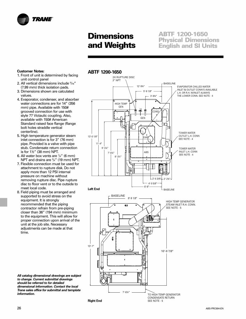
ABTF 1200-1650
Left End
Right End
Customer Notes:1. Front of unit is determined by facing
unit control panel2. All vertical dimensions include 5/16”
(7.99 mm) thick isolation pads.3. Dimensions shown are calculated
values.4. Evaporator, condenser, and absorber
water connections are for 14” (356mm) pipe. Available with 150#grooved connection for use withstyle 77 Victaulic coupling. Also,available with 150# AmericanStandard raised face flange (flangebolt holes straddle verticalcenterline).
5. High temperature generator steaminlet connection is for 3” (76 mm)pipe. Provided is a valve with pipestub. Condensate return connectionis for 1½” (38 mm) NPT.
6. All water box vents are 1/4” (6 mm)NPT and drains are 3/4” (19 mm) NPT.
7. Flexible connection must be used forattachment to rupture disk. Do notapply more than 12 PSI internalpressure on machine withoutremoving rupture disc. Pipe rupturedisc to floor vent or to the outside tomeet local code.
8. Field piping must be arranged andsupported to avoid stress on theequipment. It is stronglyrecommended that the pipingcontractor refrain from pre-pipingcloser than 36” (194 mm) minimumto the equipment. This will allow forproper connection upon arrival of theunit at the job site. Necessaryadjustments can be made at thattime.
ABTF 1200-1650Physical DimensionsEnglish and SI Units
All catalog dimensional drawings are subjectto change. Current submittal drawingsshould be referred to for detaileddimensional information. Contact the localTrane sales office for submittal and templateinformation.

27ABS-PRC004-EN
Dimensionsand Weights
Front
Back
Table DW-5 – ABTF 1200-1650 DimensionsEnglish Units
Machine Size A B1200 26’ – 11” 22’ - 2 1/2”1350 29’ – 1” 24’ - 4 1/2”1500 31’ – 3” 26’ - 6 1/2”1650 33’ – 5” 28’ - 8 1/2”
SI Units
Machine Size A B1200 8204 67691350 8865 74301500 7525 80901650 10,185 8750
Table DW-6 – English to SI UnitsCross Reference
Conversion Chart(Ft. to mm)
English Units SI Units
9 1/4" 2359 5/8" 2441' 3 7/8" 4032' 1" 6352' 2 3/4" 6792' 3 1/4" 6922' 5 3/8" 7463' 5 1/2" 10543' 6" 10673' 6 3/8" 10763' 6 3/4" 10864' 5/8" 12354' 6" 13725' 5 1/8" 16545' 8 1/8" 17305' 9 1/8" 17566' 3 1/2" 19186' 6" 19817' 6 1/4" 22927' 8 1/4" 23438' 9 1/8" 26709' 3 1/4" 282610' 8 7/8" 327311' 4" 345412' 9 3/4" 390513' 1/8" 396513' 1" 398813' 1 3/8" 399729' 1/8" 8842
ABTF 1200-1650
ABTF 1200-1650Physical DimensionsEnglish and SI Units

ABS-PRC004-EN28
Table DW-7 – Disassembly and Center ofGravity Dimensions
English
Unit Size 380-750 850-1150 1200-1650A 7’ - 1” 8’ - 2 1/4” 10’ - 2”B 3’ - 4 5/8” 4’ - 3 1/8” 5’ - 4 3/8”C 3’ - 6 1/4” 4’ - 4 3/8” 5’ - 3 1/4”D 6’ - 9” 8’ - 0 3/8” 9’ - 2 5/8”E 3’ - 2 5/8” 4’ - 5 1/8” 4’ - 6 1/2”F 7’ - 8 3/8” 10’ - 1 3/4” 12’ - 3 5/8”G 3’ - 11 1/2” 5’ - 0 3/8” 6’ - 1 7/8”H 1’ - 2 1/8” 1’ - 8 3/4” 2’ - 2 3/8”J 6’ - 0 7/8” 7’ - 5 1/8” 9’ - 7 7/8”K 2’ - 8 1/8” 3’ - 9 3/4” 4’ - 10 3/8”L 1’ - 3 1/8” 2’ - 0 5/8” 2’ - 2 3/8”M 2’ - 9 1/2” 3’ - 6 1/2” 3’ - 7 3/4”N 2’ - 8 3/4” 3’ - 11 1/4” 3’ - 9”P 1’ - 4 5/8” 1’ - 9” 1’ 8 1/8”Q 1’ - 0” 1’ - 10 3/4” 2’ 2 1/2”
SI (mm)
Unit Size 380-750 850-1150 1200-1650A 2159 2496 3099B 1032 1299 1635C 1073 1330 1606D 2057 2448 2810E 981 1349 1384F 2346 3092 3750G 1207 1534 1876H 359 527 670J 1851 2264 2943K 816 1162 1483L 384 625 670M 851 1080 1111N 832 1200 1143P 422 533 511Q 305 578 673
Two-Piece
Figure DW-1 – Disassembly Options – Right End View
Dimensionsand Weights
DisassemblyOptions
Separated Machine SectionsDisassembled machines can ship to thejob site in two or three main sections.The three-piece option ships as anevaporator/absorber section, the hightemperature generator section and thelow temperature generator/ condensersection. The two piece option will shipthe evaporator/absorber as a section andthe low temperature generator/condenser and high temperaturegenerator as a separate piece. Contactthe local Trane sales office for currentsubmittal information.
Table DW-8 – Horizon 2-Stage Steam Absorption Subassembly WeightsEnglish Units
Low and High Low Temp. Gen.High Temp. Low Temp Temp. Evap. and Cond.
Tons Gen. Gen. and Cond. Gen. and Cond. and Abs. and Evap. and Abs.380 3527 7159 10686 19523 26682440 3574 7418 10992 20398 27816500 3621 7665 11286 21185 28850575 4480 10175 14655 24835 35010660 4550 10500 15050 25700 36200750 4625 10800 15425 26500 37300850 5084 14404 19488 33264 47668950 5522 15493 21015 35427 50920
1050 4953 16546 21499 37260 538061150 6376 17606 23982 39205 568111200 7206 25825 33031 48131 739561350 6714 22512 29226 50928 734401500 7219 24029 31248 53729 777581650 7722 25603 33325 56514 82117
SI Units
Tons380 1600 3247 4847 8856 12103440 1621 3365 4986 9253 12617500 1642 3477 5119 9610 13086575 2032 4615 6648 11265 15881660 2064 4763 6827 11658 16420750 2098 4899 6997 12020 16919850 2306 6534 8840 15089 21622950 2505 7028 9532 16070 23097
1050 2247 7505 9752 16901 244061150 2892 7986 10878 17783 257691200 3269 11714 14983 21832 335461350 3045 10211 13257 23101 333121500 3275 10900 14174 24371 352711650 3503 11614 15116 25635 37248
Three-Piece

29ABS-PRC004-EN
Dimensionsand Weights Rigging
Foundation SupportThe foundation must be level, smooth,and capable of supporting the machineweight. The machine legs should bepositioned over isolation pads. Ahousekeeping pad or support rail isrecommended to elevate the machinefor maintenance. Any foundation padshould provide adequate structuralsupport and keep the installed machinelevel within 1/16-inch by length and widthfor reliable operation. Leveling marks onthe evaporator and absorber tube sheetcan be used to check the machine after itis positioned on the pad.
Chiller IsolationIsolation pads are provided with eachunit. The purpose of the isolation pad isto distribute the machine weight andminimize sound and vibrationtransmission through the buildingstructure.
Figure DW-2 – Typical Machine Rigging Points
Figure DW-3 – Unit Anchoring Detail – All Sizes
UnitBase
¾”AnchorBolt
Nut(s) and Washer(s)to Suit
5/16” ThickIsolationPad
HousekeepingPad

ABS-PRC004-EN30
Dimensionsand Weights
ServiceClearances
Rigging and Service ClearancesService clearance is required on all sidesof the machine. Pay particular attentionto the control panel door clearance andthe clearance at one end, for tubeservice.
Figure DW-4 and Table DW-8 illustratethe recommended clearances for normalservice and tube replacement. When asufficient overhead clearance exists, werecommend placing a 6-8 inch extensionunderneath the machine legs foradditional access under the chiller.
Overhead lift is the recommendedmethod when moving a machine. Beforelifting the machine, determine theapproximate location of the center ofgravity.
Figure DW-4 – Service Clearances
1Tube pull clearances for the high temperature generator for 380 through 1150 tonnage sizesmust be on the right end of the unit. For the 1200-1650 tonnage sizes, the tube pull clearancesfor the high temperature generator may be on the left or right end of the unit.
Table DW-9 – Service ClearancesUnit Size
380/440/500 575/660/750 850 950 1050 1150 1200 1350 1500 1650English Units
A 41' 6" 59' 6" 45' 6" 49' 6" 53' 6" 57' 6" 52'-2” 56’-6” 60’-10” 65’-2”B 22' 0" 31' 0" 24' 4" 26' 4" 28' 4" 30' 4" 26’-11” 29’-1” 31’-3” 33’-5”C 14' 91/2" 23' 10" 17' 1" 19' 1" 21' 1" 23' 1" 19’-2” 21’-4” 23’-6” 25’-8”D 13' 6" 22' 6" 15' 6" 17' 6" 19' 6" 21' 6" 17' 4" 19' 6" 21' 8" 23' 10"E 9' 0" 16' 0" 10' 0" 12' 0" 14' 0" 16' 0" 10’-9” 12’-11” 15’-1” 17’-3”F 6' 0" 6' 0" 5' 8" 5' 8" 5' 8" 5' 8" 6' 1" 6' 1" 6' 1" 6' 1"G 5' 0" 5' 0" 5' 6" 5' 6" 5' 6" 5' 6" 6' 2" 6' 2" 6' 2" 6' 2"H 5' 0" 5' 0" 6' 0" 6' 0" 6' 0" 6' 0" 6' 9" 6' 9" 6' 9" 6' 9"J 2' 0" 2' 0" 3' 6" 3' 6" 3' 6" 3' 6" 3' 6" 3' 6" 3' 6" 3' 6"K 15' 0" 15' 0" 18' 0" 18' 0" 18' 0" 18' 0" 19' 10" 19' 10" 19' 10" 19' 10"L 5' 0" 5' 0" 5' 6" 5' 6" 5' 6" 5' 6" 6' 3" 6' 3" 6' 3" 6' 3"M 10' 0" 10' 0" 12' 6" 12' 6" 12' 6" 12' 6" 13' 7" 13' 7" 13' 7" 13' 7"N 10' 1/2" 10' 1/2" 10' 0" 10' 0" 10' 0" 10' 0" 10' 0" 10' 0" 10' 0" 10' 0"P 4' 9" 4' 9" 6' 0" 6' 0" 6' 0" 6' 0" 6' 6" 6' 6" 6' 6" 6' 6"R 3' 0" 3' 0" 4' 4" 4' 4" 4' 4" 4' 4" 4' 10" 4' 10" 4' 10" 4' 10"S 103/4" 103/4" 1' 4" 1' 4" 1' 4" 1' 4" 1' 6" 1' 6" 1' 6" 1' 6"T 53/8" 5' 3/8" 8" 8" 8" 8" 9" 9" 9" 9"U 4X 01 5/8" 4X 01 7/8" 4X 01 7/8"
SI Units (mm)A 12649 18136 13868 15088 16307 17526 15900 17221 18542 19853B 6706 9449 7417 8026 3636 9246 8204 8864 9525 9576C 4509 7264 5207 5817 6426 7036 5842 6451 7163 7823D 4119 6858 4724 5334 5944 6553 5283 5944 6604 7264E 2743 4877 3048 3658 4267 4877 3277 3937 4597 5258F 1829 1829 1725 1725 1725 1725 1854 1854 1854 1854G 1524 1524 1676 1676 1676 1676 1879 1879 1879 1879H 1524 1524 1829 1829 1829 1829 2057 2057 2057 2057J 610 610 1067 1067 1067 1067 1067 1067 1067 1067K 4572 4572 5486 5486 5486 5486 6045 6045 6045 6045L 1524 1524 1676 1676 1676 1676 1905 1905 1905 1905M 3048 3048 3810 3810 3810 3810 4140 4140 4140 4140N 3200 3200 3048 3048 3048 3048 3048 3048 3048 3048P 1448 1448 1829 1829 1829 1829 1981 1981 1981 1981R 914 914 1321 1321 1321 1321 1473 1473 1473 1473S 273 273 406 406 406 406 457 457 457 457T 136 136 203 203 203 203 229 229 229 229U 4X 41.275 4X 47.625 4X 47.625

31ABS-PRC004-EN
Dimensionsand Weights
ColdInsulation
Low Temperature Cold InsulationCold insulation can be ordered as afactory installed option. The quantity andthe areas to be covered are illustrated inTable DW-9 andFigure DW-5.
Table DW-10 – Cold Insulation Area and LengthRefrigerant Evaporator
Storage Tank Section 6” Pipe 4” Pipe 3.5” Pipe 3.0” Pipe 2” Pipe 1/2” PipeUnit Size Sq. Ft. Sq. Ft. Ln. Ft. Ln. Ft. Ln. Ft. Ln. Ft. Ln. Ft. Ln. Ft.
English Units
380-440-500 70 170 N/A 3 N/A N/A 6 N/A575-660-750 70 234 3 N/A N/A N/A 6 N/A
850 81 195 6 5 5 5 10 8950 88 215 6 5 5 5 10 8
1050 95 230 6 5 5 5 10 81150 102 250 6 5 5 5 10 81200 80 335 6 15 N/A 5 10 111350 90 360 6 15 N/A 5 10 111500 100 385 6 15 N/A 5 10 111650 110 410 6 15 N/A 5 10 11
SI UnitsUnit Size Sq. Mtrs. (m2) Sq. Mtrs. (m2) Meters (m) Meters (m) Meters (m) Meters (m) Meters (m) Meters (m)
380-440-500 6.51 15.81 N/A .91443 N/A N/A 1.83 N/A575-660-750 6.51 21.76 .91443 N/A N/A N/A 1.83 N/A
850 7.5 18.13 1.83 1.52 1.52 1.52 3.05 2.45950 8.18 19.99 1.83 1.52 1.52 1.52 3.05 2.45
1050 8.83 21.39 1.83 1.52 1.52 1.52 3.05 2.451150 9.49 23.25 1.83 1.52 1.52 1.52 3.05 2.451200 7.44 31.15 1.83 4.57 N/A 1.52 3.05 3.351350 8.37 33.48 1.83 4.57 N/A 1.52 3.05 3.351500 9.3 35.80 1.83 4.57 N/A 1.52 3.05 3.351650 10.23 38.13 1.83 4.57 N/A 1.52 3.05 3.35
Factory Provided, Factory Installed Option
Figure DW-5 – Cold Insulation

ABS-PRC004-EN32
High Temperature Hot InsulationTo minimize heat released to theequipment room, insulation isrecommended in the following areas onthe unit. “Factory Option” insulationillustrated in Table DW-10 andFigure DW-6 can be ordered from Traneas an option. If additional insulation isdesired, the dimensions/location of“Field Supplied” are also provided.
Factory Provided, Field Installed Option
Field Provided, Field Installed Option
Figure DW-6 – Hot Insulation
Dimensionsand Weights
HotInsulation
Table DW-11 – Hot Insulation Area and LengthFactory Option Field Addition If Desired
High Low HighTemp Temp Temp Condensate FloatGen. HX HX HX Chamber 12" Pipe 10” Pipe 8” Pipe 6” Pipe 4” Pipe 3” Pipe 2½” Pipe 2” Pipe 1.5” Pipe ½” Pipe
Unit Size Sq. Ft. Sq. Ft. Sq. Ft. Sq. Ft. Sq. Ft. Ln. Ft. Ln. Ft. Ln. Ft. Ln. Ft. Ln. Ft. Ln. Ft. Ln. Ft. Ln. Ft. Ln. Ft. Ln. Ft.English Units
380-440-500 107 28 23 4.5 14 NA NA 3 NA 8 NA 18 29 10 NA575-660-750 160 31 26 5 14 NA NA 3 NA 8 NA 18 38 10 NA
850 265 23 15 6 19 NA 9 NA 12 27 46 2 9 5 13950 295 25 19 7 19 NA 9 NA 12 27 46 2 9 5 131050 320 27 20 9 19 NA 9 NA 12 27 46 2 9 5 131150 345 29 21 9 19 NA 9 NA 12 27 46 2 9 5 131200 270 37 22 12 19 8 NA NA 56 67 4 21 14 7 171350 300 40 26 12 19 8 NA NA 56 67 4 21 14 7 171500 330 42 28 13 19 8 NA NA 56 67 4 21 14 7 171650 355 43 29 14 19 8 NA NA 56 67 4 21 14 7 17
SI UnitsSq. Sq. Sq. Sq. Sq.
Mtrs. Mtrs. Mtrs. Mtrs. Mtrs. Meters Meters Meters Meters Meters Meters Meters Meters Meters MetersUnit Size (m2) (m2) (m2) (m2) (m2) (m) (m) (m) (m) (m) (m) (m) (m) (m) (m)
380-440-500 9.95 2.60 2.14 .42 1.30 NA NA .914 NA 2.44 NA 5.49 8.84 3.05 NA575-660-750 14.88 2.88 2.42 .46 1.30 NA NA .914 NA 2.44 NA 5.49 11.58 3.05 NA
850 24.65 2.14 1.40 .56 1.77 NA 2.74 NA 3.66 8.23 14.02 .61 2.74 1.52 3.96950 27.44 2.32 1.77 .65 1.77 NA 2.74 NA 3.66 8.23 14.02 .61 2.74 1.52 3.961050 29.76 2.51 1.86 .84 1.77 NA 2.74 NA 3.66 8.23 14.02 .61 2.74 1.52 3.961150 32.08 2.70 1.95 .84 1.77 NA 2.74 NA 3.66 8.23 14.02 .61 2.74 1.52 3.961200 25.11 3.44 2.05 1.12 1.77 2.438 NA NA 17.07 20.42 1.22 6.40 4.26 2.13 5.181350 27.9 3.72 2.42 1.12 1.77 2.438 NA NA 17.07 20.42 1.22 6.40 4.26 2.13 5.181500 30.69 3.90 2.60 1.21 1.77 2.438 NA NA 17.07 20.42 1.22 6.40 4.26 2.13 5.181650 33.01 4.0 2.70 1.30 1.77 2.438 NA NA 17.07 20.42 1.22 6.40 4.26 2.13 5.18
33ABS-PRC004-EN
Dimensionsand Weights
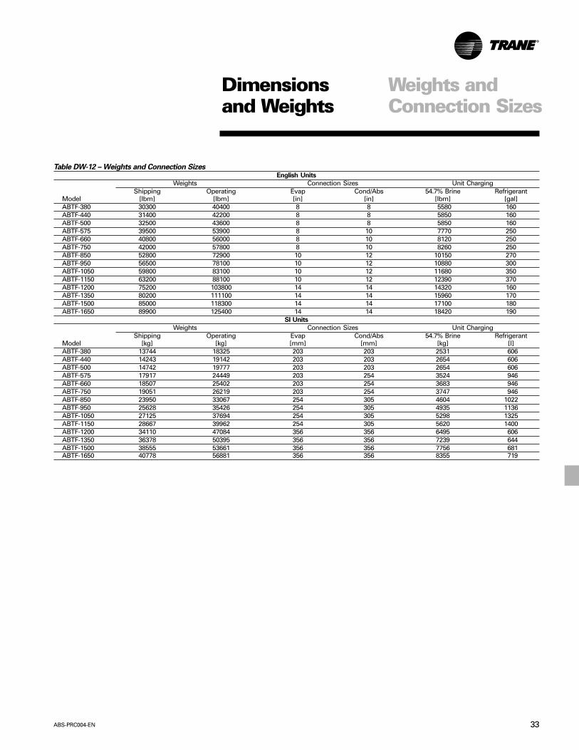
Table DW-12 – Weights and Connection SizesEnglish Units
Weights Connection Sizes Unit ChargingShipping Operating Evap Cond/Abs 54.7% Brine Refrigerant
Model [lbm] [lbm] [in] [in] [lbm] [gal]ABTF-380 30300 40400 8 8 5580 160ABTF-440 31400 42200 8 8 5850 160ABTF-500 32500 43600 8 8 5850 160ABTF-575 39500 53900 8 10 7770 250ABTF-660 40800 56000 8 10 8120 250ABTF-750 42000 57800 8 10 8260 250ABTF-850 52800 72900 10 12 10150 270ABTF-950 56500 78100 10 12 10880 300ABTF-1050 59800 83100 10 12 11680 350ABTF-1150 63200 88100 10 12 12390 370ABTF-1200 75200 103800 14 14 14320 160ABTF-1350 80200 111100 14 14 15960 170ABTF-1500 85000 118300 14 14 17100 180ABTF-1650 89900 125400 14 14 18420 190
SI Units
Weights Connection Sizes Unit ChargingShipping Operating Evap Cond/Abs 54.7% Brine Refrigerant
Model [kg] [kg] [mm] [mm] [kg] [l]ABTF-380 13744 18325 203 203 2531 606ABTF-440 14243 19142 203 203 2654 606ABTF-500 14742 19777 203 203 2654 606ABTF-575 17917 24449 203 254 3524 946ABTF-660 18507 25402 203 254 3683 946ABTF-750 19051 26219 203 254 3747 946ABTF-850 23950 33067 254 305 4604 1022ABTF-950 25628 35426 254 305 4935 1136ABTF-1050 27125 37694 254 305 5298 1325ABTF-1150 28667 39962 254 305 5620 1400ABTF-1200 34110 47084 356 356 6495 606ABTF-1350 36378 50395 356 356 7239 644ABTF-1500 38555 53661 356 356 7756 681ABTF-1650 40778 56881 356 356 8355 719
Weights andConnection Sizes

ABS-PRC004-EN34
JobsiteConnections
Steam SupplyPiping
Steam SupplyFigure JC-1 illustrates a typical steamsupply piping illustration that includesthe appropriate hardware.
The steam supply piping should bedesigned in accordance with gooddesign practice, providing strainers,unions and gate valves for ease ofoperation and maintenance. A properlysized steam modulating valve, based ondesign flow and pressure droprequirements, is provided factorymounted by The Trane Company.
A hand valve in the steam supply pipingis recommended when the machine willbe out of operation for an extendedperiod. The modulating steam valvemay experience a small amount ofleakage during shutdown. This leakagemay result in heating of the equipmentroom unless the machine is properlyvalved off with a hand valve.
In all applications, it is recommendedthat the steam supply pressure to thecontrol valve inlet not exceed design toassure proper valve close off. If steamsupply pressures exceed design, apressure reducing station should beused to control the steam pressure to thevalve.
The unit control has adjustable featureswhich minimize steam draw on start-up.The adjustable steam control featureallows the user to adapt the machine tothe available steam source capability.
Table JC-1 – Steam Supply Piping ResponsibilitiesMaterial Provided By Installed By
Item Trane Other Trane OtherSteam Control Valve X XT-Type Strainer, Flanged connections, gate valve, drip legw/dirt pocket, float and thermostatic trap, pressure gauge vent X Xand valve, pressure reducing valve, pressure gauge, relief valve.
Steam Supply(Above 150 psig)
Steam Supply(150 psig)
To CondensateReturn System
See Detail “A”
Steam Chest
115 psig
Detail “A”Test Gauge
PressureGauge
ShutoffValve
(Vent To Atmosphere)
4
2
8
9
To4
2
2
4
7
1 3
5
6
1. Steam Supply Valve (Detail “B”)2. Strainer3. Union or Flanged Connection4. Gate Valve5. Drip Leg6. Float and Thermostatic Trap7. Pressure Gauge, Vent and Shutoff Valves (Detail “A”)8. Pressure Reducing Valve9. Pressure Gauge
10. Relief Valve
Note: Nominal steam valve is selected for a pressure dropof 5 to 10 psig @ full load. If steam supply pressureexceeds the selected valve pressure drop, a pressurereducing valve (Item 8) may be needed.
Figure JC-1 – Typical Steam Supply Piping10
Detail “B”- Steam Supply Valve

35ABS-PRC004-EN
JobsiteConnections
Hot WaterPiping
Hot Water PipingExpansion of the tubes in the generatoris a normal condition due to the watertemperatures reached in the tubebundle. All Trane absorption units use acombination of fixed and floating tubesupports to control the direction ofgenerator tube expansion. Normally, thisexpansion is uniformly distributedthroughout the bundle. However, duringshutdown, when very small amounts ofhot water may leak through the valve,the first tube pass reaches thetemperature of the hot water while theremaining passes are cold.Consequently, it is recommended thatthe supply and return piping include acirculating pump, check valve and coldlegs to protect the generator tubes fromthe unequal expansion should thecontrol valve leak during unit shutdown.This system is designed to eliminate hotwater flow through the generator duringunit shutdown.
Figure JC-2 illustrates the recommendedmethod for applying up to 370 F(+187.8 C) hot water to the generatorsection. This generator design is rated to400 psig. The piping includes acirculating pump and secondary hotwater loop and should be designed inaccordance with good design practiceproviding strainers, unions and gatevalves for ease of operation andmaintenance. The pump circulates waterthrough the generator at a constant rateand the temperature within the loop iscontrolled by mixing recirculated waterwith hot water from the supply main.A properly sized modulating two-waypositive shutoff valve controls theamount of water leaving the loop andtherefore, determines the temperature ofmixed water entering the generator.This valve is provided by The TraneCompany. This valve is also selectedbased on design flow and pressure droprequirements submitted by theconsulting engineer.
The hot water inlet must always beconnected to the right side of themachine. Right hand is determined bystanding in front of the unit facing thecontrol panels.
Table JC-2 – Hot Water Supply Piping ResponsibilitiesMaterial Provided By Installed By
Item Trane Other Trane OtherCapacity Control Valve X XGate valve, balance valve, Y-type strainer w/valve,bypass circuit, check valve, thermometer, pressure gauge, X Xvent shutoff valve, union or flanged connection circulating pump
Figure JC-2 – Hot Water Supply Temperature Piping

ABS-PRC004-EN36
JobsiteConnections
CondensatePiping
Condensate HandlingFigure JC-3 illustrates a method ofcondensate drain. At full load, thecondensate leaving a two-stageabsorption chiller is approximately 210 F(+98.9 C). This temperature minimizesflashing in a low pressure or opencondensate return system. An automaticcondensate trapping system is providedas standard with the unit. This system isdesigned to dump condensate into anatmospheric return.
Figure JC-3 – Typical Condensate Piping
Table JC-3 – Condensate Return Piping ResponsibilityMaterial Provided By Installed By
Item Trane Other Trane OtherDrainer X XConnecting Piping X X

37ABS-PRC004-EN
JobsiteConnections
CoolingWater Piping
Cooling Water PipingFigure JC-4 and JC-5 illustrate therecommended methods to apply coolingwater to the Trane absorption machine.In those cases where a cooling towerbypass is not used, multiple coolingtower fans are recommended.
The cooling water piping design forabsorption chillers differs fromconventional reciprocating andcentrifugal systems in that cooling waterpasses through the absorber section ofthe machine prior to entering thecondenser. The cooling water flow mustbe controlled by the absorption machineas a function of normal control andmachine safety.
Trane Horizon™ two-stage absorptionmachines are designed to start-up withcooling tower water temperatures as lowas 45 F (+7.2 C) and operate withtemperatures as low as 55 F (+12.8 C).In typical applications, the machine isselected on the basis of the cooling watertemperature available at full load. This isusually 85 F (+29.4 C).
With the cooling tower sized for designconditions, the temperature of thecooling water supplied to the unit willdecrease with any decrease in coolingload or depression of outside wet bulbtemperature. These reduced coolingwater temperatures will normally tend toincrease the capacity potential of theabsorption machine. The Trane controlsystem takes advantage of this improvedefficiency by using automatic controlsthat limit the energy input to the machinebased on entering cooling watertemperature.
Cooling water temperature control isalways required. At light loads with coldoutside conditions, cycling of the coolingtower fan will result in undesirablevariation in steam demand and leavingchilled water temperature. Consequently,Trane recommends consideration ofmultiple speed tower fans or a coolingtower bypass valve to reach equilibriumat all load conditions. Rate of changeallowable is 1 degree per minute.
Water temperature sensors are factory-installed on the entering and leavingsides of the absorber and condenserwater connections. The operatingtemperatures can be monitored from thecontrol panel.
Figure JC-4 – Cooling Water Piping with Cooling Tower
Figure JC-5 – Cooling Water Piping with Well or River Water
Table JC-4 – Condenser/Absorber Piping ResponsibilityMaterial Provided By Installed By
Item Trane Other Trane OtherCrossover Pipe X XFlow Switch (optional) X X
X orBalancing valve, gate valve, thermometer (optional),pressure gauge vent and shutoff valve, Victaulic X Xor flange connection, pipe stub, strainer, pump.

ABS-PRC004-EN38
MechanicalSpecifications
GeneralUnit is a complete double effect steam orhot water fired absorption chillerpackage built in an ISO 9001environment. Chiller consists of hightemperature generator, low temperaturegenerator/condenser section,evaporator/absorber section, controls,pumps, heat exchangers, and steamcontrol valve. All units are of hermeticdesign, factory assembled and leaktested prior to shipment. Units can beseparated and shipped disassembled forrigging purposes. The control panel,energy valve, and sensors are factoryinstalled. Unit is painted prior toshipping with two coats consisting of awater base air dry primer and finish coat.Standard method of shipment is by truckfrom the USA.
Low Temperature Generator/Condenser-Evaporator/AbsorberThe shell material is carbon steel.Standard low temperature generatortube material is cupro-nickel, Evaporatoris copper, absorber is cupro-nickel andcondenser is copper. Tubes aremechanically rolled into the tubesheetsand are replaceable from either end.Condenser, evaporator and absorbertube supports are fixed. The lowtemperature generator consists of fixedand floating tube supports to allow foreven tube expansion. Spray systems arereplaceable from end of unit withoutsacrificing the hermetic integrity of theunit.
Design working pressure for the waterboxes is 150 psig (10.5 kg/cm2). All tubebundles are tested at 150 percent ofdesign working pressure. All waterboxes, except the second-stagegenerator, have gasketed removablecovers for access. Marine type waterboxes are provided on the condenserand absorber section. Water connectionsare provided with either Victualic orraised-face flanged connections.
Heat ExchangersThree welded hermetic plate solutionheat exchangers are provided toimprove unit performance. Heatexchanger surfaces are 300 seriesstainless steel.
PumpsSolution and refrigerant are circulated bymeans of four hermetic, single stagecentrifugal pumps. The pump impeller iscast iron with a steel shaft supported bytwo tapered carbon bearings. Thebearings are lubricated and the fluid thatis pumped cools the motor. Anadjustable frequency drive is providedon the low temperature generator pumpand absorber pump to provide solutioncontrol.
PurgePurge system includes a collectionchamber in absorber section, an eductorfor moving non-condensables to thecondenser, Purifier™ Purge to collect thenon-condensables in an external storagetank, and vacuum pump for removal ofthe non-condensables. The purgeoperates automatically to remove non-condensables from the unit duringperiods of chiller operation andshutdown. Logging of purge informationis provided via the unit control panel.
High Temperature GeneratorThe shell is carbon steel. Tube sheets aresteel and standard generator tubes areconstructed of stainless steel. The hightemperature generator has fixed andfloating tube supports to allow for eventube expansion. The steam side of thegenerator is designed and stamped for150 PSI ASME construction. Unit hightemperature generator includes rupturedisk which is sized to meet ANSI/ASHRAE STD 15. Factory mounted andwired energy control valve is standard.
39ABS-PRC004-EN
MechanicalSpecifications
Control PanelThe UCP2™ is a microprocessor-basedchiller control system that providescomplete stand-alone operation. It is afactory mounted package including a fullcompliment of controls to safely andefficiently operate the absorption liquidchiller. The UCP2 consists of thefollowing items:
Control Functions:
• Chilled water temperature control• Concentration control
System Features and Functions:
• User interface with a 40 character,2 line display and a 16 key keypad,capable of displaying 7 languages andSI or English units
• Passwords for protection of unit setupand configuration
• Chilled water pump control• Absorber/Condenser pump control• Automatic and manual control of
solution and refrigerant pumps• Economical solution flow control of the
low temperature solution pump andabsorber pump via an adjustablefrequency drive
• Anti-crystallization through dilutioncontrol
• Automatic and manual purge system• Chilled water reset• Two-way valve assembly for hot water
flow control or steam flow control.
Adaptive Limits:
• Evaporator water temperature limit• High interstage pressure limit• High interstage temperature limit• Low absorber/condenser limit• Soft-loading control
System Protection:
• Evaporator freeze protection• Chilled water flow confirmation• Cooling water flow confirmation• High interstage pressure cutout to
prevent excessive pressure• Emergency stop/shutdown• Under/over voltage detection
Monitor and Displays:
• Chilled water temperature entering andleaving
• Absorber/condenser watertemperature entering and leaving
• Solution concentrations• Solution temperatures• Interstage pressure• Total pump current• Unit voltage• Chiller run time and starts• Purge operation and run time
Interfaces to UCP2:
• External machine manual reset alarmindication output
• External machine auto reset warningindication output
• External limit warning indicationoutput
• Interstage pressure relief requestoutput
• Maximum capacity indication output• External auto-stop/emergency
shutdown• External chilled water setpoint
ABS-PRC004-EN40
MechanicalSpecifications
Contractor Responsibilities1. Install the unit on a level surface.
Neoprene isolation pads supplied bythe manufacturer shall be placedunder the unit.
2. Connect-unit control panel to alloperating external safety andauxiliary control devices.
3. Insure that piping adjacent to themachine does not restrict removal ofheaders for inspection, cleaning andremoving tubes.
4. Provide gauge cocks and optionalthermometer wells for temperatureand pressure readings at the inletand outlet of the evaporator, at theinlet and outlet of the absorber, andat the outlet of the condenser.
5. Provide balancing valves in allexternal water circuits to allowbalance and trim of the system.
6. Provide and install strainers ahead ofall pumps and automatic modulatingvalves to insure proper pump andvalve operation.
7. Insulate the chilled water headersand other portions of the unit, aspointed out in the manufacturer’sinstallation literature to preventcondensation on cold surfaces andheat loss from hot surfaces to theequipment room. External unit pipeswith surface temperaturessufficiently hot to constitute a dangerto operating personnel shall also beinsulated.
8. Provide and install a flow switch inthe chilled water circuit and interlockit with the starting control circuit ofthe unit. Proof of flow is requiredprior to permitting unit operation.Provide and install a flow switch inthe condenser water circuit, whichshall be interlocked with the startingcontrol circuit of the unit such thatproof of flow is required to preventmachine damage
9. Provide necessary distilled ordemineralized water for refrigerantcharge, and trim charge.
10. Provide labor to charge the machinewith lithium bromide solution andrefrigerant water, and assist inmachine starting and calibrationunder supervision of themanufacturer’s representative.
11. Provide sufficient sized vacuumpump and personnel to evacuate theunit prior to charging (if required).
12. Field assemble machines (if required)and leak test in accordance withinstructions in the manufacturer’sinstallation bulletin.
13. Connect the rupture disc to anappropriate floor drain or retentionchamber. The vent piping shall besupported and connected by aflexible connector to prevent stress atthe connection.
14. Install any control componentsprovided by the manufacturer forinstallation external to the machine.
15. Furnish and install, external to theunit control panel, a separately fuseddisconnect switch, if not provided.
16. Install required power supply wiringto the control panel. Use copper wireonly.
Insulation RequiredInsulation is required on hot areas toprotect operating and service personneland on cold areas to prevent sweating.Cold insulation can be ordered as afactory installed option. Hot insulationfor the high temperature generator; high,low and condensate heat exchangers;float chamber and 8" and 10" (203 and254 mm) piping can be ordered as a fieldinstalled option. Hot insulation for theconnecting piping is field provided, fieldinstalled.
Insulation for the hot insulation areashould be 3-inch (76.2 mm) #8 densitymineral wool applied over stud weldpins it should be applied on thegenerator, high temperature heatexchanger and associated piping.
Insulation for cold insulation area shouldbe ¾-inch (13 mm) Armaflex or equalshould be applied to evaporatorwaterboxes, refrigerant storage tank,refrigerant pump and refrigerant piping.
Unit OptionsUnit options shall include:• 300 psi waterboxes• Marine-style waterboxes on the
evaporator• Special tubing• Disassembled unit• Factory installed cold insulation• NEMA 4X controls

41ABS-PRC004-EN
Standard Features/Options/DesignSpecial Options
Standard Features• Lithium bromide filter• Victaulic water connections• 50,000 hours design life solution
pumps• Industrial-grade tubes unmatched in
the industry1st Stage Generator – 409 StainlessSteel2nd Stage Generator – .028” wall95/5 CuNiEvaporator – .025” CopperAbsorber – .022” wall 95/5 CuNiCondenser – .028” wall Copper
• Factory mounted and testedmicroprocessor controls
• 150 PSIG water boxes• Marine water boxes on the condenser
and absorber sections• Factory installed cooling-water
crossover pipe• Industrial duty factory mounted energy
valve• Environmentally friendly inhibitor• Fixed and floating tube supports which
allow for expansion of tubes withoutproblems of high stress
• Designed, manufactured and tested forsuperior hermetic integrity
• Fully automatic purge
Options• 150 PSIG raised face flanges for the
evaporator, condenser, and absorberwater connections
• Major component disassembly in twoor three pieces for installations that canbenefit from the handling of smallercomponents
• Factory provided, factory installed coldinsulation
• Factory provided, field installed hotinsulation
Design Special OptionsHorizon™ chiller production in La CrosseWI maintains its high productionstandards for its standard product lineswhile also producing design specialsunder the same high standards. Designspecial options include:• 035-.049 wall tubes• 90/10 CuNi, stainless steel and titanium
tubes• 300 PSIG water boxes• Epoxy coated waterboxes• NEMA 4 and 4X for additional chiller
protection against to outdoor elementsor water impingement from variousdirections
• Alternate pass arrangements• Explosion-proof for specifications that
require additional chiller/control panelenclosure
• Marine style evaporator water boxes• Epoxy paint – primer and finish ships
with chiller for added protectionagainst outdoor elements or corrosiveenvironments such as chemical plantsor salt water locations
• Special paints for special applications• Sacrificial anodes for use where
corrosive water is present• Gantries for “swing out” end plates for
easy tube cleaning capability• Custom control configurations• Specials for compliance with code/
market requirements• Special packaging requirements• Options for using non-standard heat
sources• Hinged water box covers


StandardConversionTable
Since The Trane Company has a policy of continuous product and product data improvement, it reservesthe right to change design and specifications without notice.
Literature Order Number
File Number
Supersedes
Stocking LocationThe Trane Company
An American Standard Company
www.trane.com
For more information contactyour local sales office ore-mail us at [email protected]
ABS-PRC004-EN
PL-RF-ABS-000-PRC004-EN-0101
ABS-DS-4 January 2000
La Crosse