Embed Size (px)
Citation preview

TRAK® TRL 1440EX Lathe ProtoTRAK® ELX CNC
Safety, Programming, Operating & Care Manual
Document: P/N 26010 Version: 052808
Southwestern Industries, Inc. 2615 Homestead Place Rancho Dominguez, CA 90220-5610 USA T | 310.608.4422 | F | 310. 764.2668 Service Department: 800.367.3165 e-mail: [email protected] | [email protected] | web: southwesternindustries.com

Copyright © 2008, Southwestern Industries, Inc. All rights are reserved. No part of this publication may be reproduced, stored in a retrieval system, or transmitted, in any form or by any means, mechanical, photocopying, recording or otherwise, without the prior written permission of Southwestern Industries, Inc. While every effort has been made to include all the information required for the purposes of this guide, Southwestern Industries, Inc. assumes no responsibility for inaccuracies or omission and accepts no liability for damages resulting from the use of the information contained in this guide. All brand names and products are trademarks or registered trademarks of their respective holders. Southwestern Industries, Inc. 2615 Homestead Place Rancho Dominguez, CA 90220 Phn 310/608-4422 Fax 310/764-2668 Service Department Phn 800/367-3165 Fax 310/886-8029

i Southwestern Industries, Inc.
TRAK TRL EX Lathe and ProtoTRAK ELX CNC Safety, Programming, Operating & Care Manual
Table of Contents 1.0 Introduction 2.0 Safety Specifications & Lubrication 2.1 Safety Publications 3 2.2 Danger, Warning, Caution and Note
Labels and Notices Used in this Manual 3 2.3 Safety Precautions 6 3.0 Description 3.1 Control Specifications 9
3.1.1 Basic System Specifications 9 3.2 Display Pendant 10 3.2.1 Pendant Front 10 3.2.2 Pendant Back 12 3.3 Machine Specifications 14 3.4 Spindle Motor 15 3.5 Electronic Handwheels 15 3.6 Lubrication System 15 3.6.1 Headstock 15 3.6.2 Manual Lubrication Pump 15 3.7 Electrical Cabinet 16 3.8 Sliding Doors & Interlock Switch 16 3.9 Optional Equipment 16 3.9.1 Collet Closer 16 3.9.2 Chuck 16 3.9.3 Coolant Pump 16 3.9.4 Steady Rest 16 3.9.5 Tooling Kit 16 3.9.6 Remote Stop/Go Switch 17 3.9.7 Follow Rest 17 3.9.8 Work Lamp 17 3.9.9 Tailstock 17 3.9.10 440 Volt Option 17
4.0 Basic Operation 4.1 Switching the TRAK TRL On/Off 19 4.2 Switching the ProtoTRAK ELX CNC On 19 4.3 Shutting down the ProtoTRAK ELX CNC 19 4.4 Using the Electronic Handwheels 19 4.5 Emergency Stop 20 4.6 Coolant Pump 20 4.7 Help Functions 20 4.8 Tool Pedestal 20 4.9 Tail Stock 20 4.10 Spindle Operation 20 4.11 Spindle Speed Ranges 20 5.0 Definitions, Terms & Concepts 5.1 ProtoTRAK ELX CNC Axis Conventions 21 5.2 Absolute & Incremental Reference 21 5.3 Referenced & Non-Referenced Data 21 5.4 Tool Tip Radius Compensation 22 5.5 Tool Offset 22 5.6 Connective Events 23 5.7 Conrad 23
5.8 Chamfer 24 5.9 Absolute, Tool & Program References 25 6.0 DRO Mode 6.1 Enter DRO Mode 27 6.2 DRO Functions 27 6.3 Fine & Coarse Resolution 28 6.4 Jog 28 6.5 Do One 28 6.5.1 Taper Do One 29 6.5.2 Radius Do One 30 6.5.3 Fillet Do One 30 6.5.4 Power Feed 30 6.6 Go To 31 6.7 Return to Home 31 6.8 Tool # 31 6.10 Tool Tip Radius Compensation in
DRO Mode 32 7.0 Program Mode 7.1 Enter Program Mode & Assign a Program
Name 33 7.2 Programming Strategy & Procedures 34 7.3 Programming Events 35 7.3.1 Position Events 36 7.3.2 Drill/Bore Events 36 7.3.3 Turn Events 37 7.3.4 ARC Events 38 7.3.5 Cycle Events 38 7.3.6 Thread Events 42 7.3.7 Repeat Events 43 7.3.8 Finish Cuts 43 8.0 Changing or Correcting Programs 8.1 Deleting a Partially Programmed Event 45 8.2 Editing Data while Programming an Event 45 8.3 Editing Previously Programmed Events 45 8.4 Changing the Feedrates 45 8.5 Changing a Part Number 48 8.6 Saving Changes to a Program 48 8.7 Erasing an Entire Program 48 9.0 Set-Up Mode 9.1 Enter Set-Up Mode 49 9.2 Tool Set-Up 49
9.2.1 Practical Technique for Accurate Tool Setting 51
9.2.2 Tool Set-Up When Adding or Changing Tools 51
9.3 Tool Path 52 9.3.1 Soft Keys in Tool Path 52 9.4 Set Home 52 9.4.1 Home Positions 52 9.5 Save Tools 53 9.6 Serv Codes 53

ii Southwestern Industries, Inc.
TRAK TRL EX Lathe and ProtoTRAK ELX CNC Safety, Programming, Operating & Care Manual
10.0 Run Mode 10.1 Starting to Run 55 10.2 Program Run 56 10.3 Door Position in Run Mode 57 10.4 Program Run Messages 58 10.5 Stop 58 10.6 Feedrate & Spindle Speed Override 58 10.7 Threading Exceptions 58 10.8 Data Errors 58 10.9 Fault Messages 58 11.0 Program In/Out Mode 11.1 Cautions About Opening & Deleting
Programs 59 11.2 Program Formats & Labeling 59 11.3 Saving & Opening Programs from the
ProtoTRAK ELX Internal Storage 59 11.4 File Transfer & Backup 60 11.5 CAM/G-Code Files 60
11.5.1 G-Codes Recognized by ProtoTRAK ELX 61
12.0 Tutorial & Sample Program

1 Southwestern Industries, Inc.
TRAK TRL EX Lathe and ProtoTRAK ELX CNC Safety, Programming, Operating & Care Manual
1.0 Introduction Congratulations on your purchase of a TRAK 1440EX toolroom lathe with the ProtoTRAK ELX CNC control. From manual to short-run production, TRAK lathes are the most efficient machines you can use. They are more efficient than engine lathes, even for manual jobs. Slide the door back and operate the ELX CNC in DRO mode. You have the convenience of large dimensional information on the easy-to-read CNC screen, and the efficiency of powerful DO ONE cycles to quickly perform a taper, radius, or fillet without writing an entire program. The operation of the ELX CNC has been painstakingly refined to bring you the most useful CNC technology while retaining the ease of use that has made ProtoTRAK the top brand in machines and controls for low volume production. This manual describes the operation of all basic and optional features in the appropriate context. Section 2 of this manual provides very important safety information. It is highly recommended that all operators of this product review this safety information carefully.

2 Southwestern Industries, Inc.
TRAK TRL EX Lathe and ProtoTRAK ELX CNC Safety, Programming, Operating & Care Manual

3 Southwestern Industries, Inc.
TRAK TRL EX Lathe and ProtoTRAK ELX CNC Safety, Programming, Operating & Care Manual
2.0 Safety Specifications & Lubrication The safe operation of the TRAK TRL 1440 Lathe and ProtoTRAK ELX CNC depends on its proper use and the precautions taken by each operator.
• Read and study this manual. Be certain that every operator understands the operation and safety requirements of this machine before its use.
• Always wear safety glasses and safety shoes.
• Always stop the spindle and check to ensure the CNC control is in the stop mode before
changing or adjusting the tool or workpiece.
• Never wear gloves, rings, watches, long sleeves, neckties, jewelry, or other loose items when operating, or around the machine.
• Use adequate point of operation safeguarding. It is the responsibility of the employer to
provide and ensure point of operation safeguarding per ANSI B11.6-2001.
2.1 Safety Publications Refer to and study the following publications for assistance in enhancing the safe use of this machine: Safety Requirements For The Construction, Care And Use of Lathes (ANSI B11.6-2001). Available from the American National Standards Institute, 11 West 42nd Street, New York, NY 10036. Concepts And Techniques Of Machine Safeguarding (OSHA Publication Number 3067). Available from The Publication Office - O.S.H.A., U.S. Department of Labor, 200 Constitution Avenue, NW, Washington, DC 20210. All other regulations specific to the State in which the machine is installed.
2.2 Danger, Warning, Caution, and Note Labels and Notices
As Used In This Manual DANGER - Immediate hazards that will result in severe personal injury or death. Danger labels on the machine are red in color. WARNING - Hazards or unsafe practices that could result in severe personal injury and/or damage to the equipment. Warning labels on the machine are gold in color. CAUTION - Hazards or unsafe practices that could result in minor personal injury or equipment/product damage. Caution labels on the machine are gold in color. NOTE - Call attention to specific issues requiring special attention or understanding.

4 Southwestern Industries, Inc.
TRAK TRL EX Lathe and ProtoTRAK ELX CNC Safety, Programming, Operating & Care Manual
WARNING! Do not shift headstock gears while spindle or
motor is running.
220 or 440 Volts
Safety & Information Labels Used on the TRAK TRL 1440 EX Lathe
It is forbidden by OSHA regulations and by law to deface, destroy or remove any of these labels

5 Southwestern Industries, Inc.
TRAK TRL EX Lathe and ProtoTRAK ELX CNC Safety, Programming, Operating & Care Manual
Safety & Information Labels Used on the TRAK TRL 1440EX Lathe
It is forbidden by OSHA regulations and by law to deface, destroy or remove any of these labels

6 Southwestern Industries, Inc.
TRAK TRL EX Lathe and ProtoTRAK ELX CNC Safety, Programming, Operating & Care Manual
2.3 Safety Precautions
WARNING! Use only chucks which are rated to the maximum RPM of the lathe.
1. Do not operate this machine before studying and understanding the manual.
2. Do not run this machine without knowing the function of every control key, button, knob,
or handle. Ask your supervisor or a qualified instructor for help when needed.
3. Protect your eyes. Wear approved safety glasses (with side shields) at all times.
4. Don't get caught in moving parts. Before operating this machine, remove all jewelry, including watches and rings, neckties, and any loose-fitting clothing.
5. Keep your hair away from moving parts. Wear adequate safety head gear.
6. Protect your feet. Wear safety shoes with oil-resistant, anti-skid soles, and steel toes.
7. Take off gloves before you start the machine. Gloves are easily caught in moving parts.
8. Remove all tools (wrenches, chuck keys, etc.) from the machine before you start. Loose
items can become dangerous flying projectiles.
9. Never operate any machine tool after consuming alcoholic beverages, or taking strong medications, or while using non-prescription drugs.
10. Protect your hands. Stop the machine spindle and ensure that the CNC control is in the
STOP mode:
• Before changing tools. • Before changing parts. • Before you clear away the chips, oil or coolant. Always use a chip scraper or
brush. • Before you make an adjustment to the part, chuck, coolant nozzle or take
measurements. • Before you open safeguards (protective shields, etc.). Never reach for the part,
tool, or fixture around a safeguard.
11. Protect your eyes and the machine as well. Don't use a compressed air hose to remove the chips or clean the machine (oil, coolant, etc.).
12. Stop and disconnect the power to the machine before you change belts, pulley, gears, etc.
13. Keep work area well lighted. Ask for additional light if needed.
14. Do not lean on the machine while it is running.
15. Prevent slippage. Keep the work area dry and clean. Remove the chips, oil, coolant and
obstacles of any kind around the machine.

7 Southwestern Industries, Inc.
TRAK TRL EX Lathe and ProtoTRAK ELX CNC Safety, Programming, Operating & Care Manual
16. Avoid getting pinched in places where the spindle, carriage, cross slide or sliding door create "pinch points" while in motion.
17. Securely clamp and properly locate the workpiece in the chuck or in the fixture. Use
proper tool holding equipment.
18. Use correct cutting parameters (speed, feed, and depth of cut) in order to prevent tool breakage.
19. Use proper cutting tools for the job.
20. Prevent damage to the workpiece or the cutting tool. Never start the machine (including the rotation of the spindle) if the tool is in contact with the part.
21. Don't use dull or damaged cutting tools. They break easily and may become airborne.
Inspect the sharpness of the edges, and the integrity of cutting tools and their holders.
22. Large overhangs on cutting tools when not required result in accidents and damaged parts.
23. Prevent fires. When machining certain materials (magnesium, etc.) the chips and dust are highly flammable. Obtain special instruction from your supervisor before machining these materials.
24. Prevent fires. Keep flammable materials and fluids away from the machine and hot,
flying chips.
25. Never change gears when the spindle is rotating.
26. Do not rotate the spindle by hand unless the Red Emergency Stop button is pressed.
27. Guard against stock whipping hazard. A rotating workpiece extending beyond the normal extremities of the headstock is a hazard. Either avoid this practice or equip the lathe with a guard such as a stock tube.

8 Southwestern Industries, Inc.
TRAK TRL EX Lathe and ProtoTRAK ELX CNC Safety, Programming, Operating & Care Manual

9 Southwestern Industries, Inc.
TRAK TRL EX Lathe and ProtoTRAK ELX CNC Safety, Programming, Operating & Care Manual
3.0 Description
3.1 Control Specifications In its base form, the ProtoTRAK ELX CNC is powerful and easy to use.
The list below summarizes the features and specifications. Each feature is described in more detail in the appropriate section of the manual.
3.1.1 Basic System Specifications
Control Hardware • Two-axis CNC, two-axis DRO • Electronic handwheels for manual operation • Precision Ball Screws • 7” Color LCD • Rugged Industrial PC • Polycarbonate Sealed Membrane Keypad to lock out contamination • On board IDR flash memory storage for part programs • 2 USB connectors • Override of program feedrate • Clean front panel with few hard keys
Software Features – General Operation • Clear, uncluttered screen display • Prompted data inputs • English language – no codes • Soft keys - change within context • Windows® operating system • Color graphics with adjustable views • Inch/mm selectable • Convenient modes of operation (see below) • CAM file program run • Machine tool error compensation and backlash compensation • Selectable in/mm measurement readout • Jog from 1 to 100 ipm
Program Mode Features • Geometry-based programming • Incremental and absolute dimensions • Automatic tool nose radius compensation • Circular interpolation • Linear interpolation • Look –graphics with a single button push • List step – graphics with programmed events displayed • Conrad – one input for automatic corner radius programming • Chamfer – one input for automatic chamfer programming • Canned Cycles – Position, Drill/Bore, Turn, Arc, Cycle, Thread

10 Southwestern Industries, Inc.
TRAK TRL EX Lathe and ProtoTRAK ELX CNC Safety, Programming, Operating & Care Manual
3.2 Display Pendant
3.2.1 Pendant Front Keyboard Hard Keys GO: initiates motion in Run
STOP: halts motion during Run
LOOK: part graphics in Program mode INC/ABS: switches all or one axis between incremental and absolute
INC SET: loads incremental dimensions and general data
ABS SET: loads absolute dimensions and general data
X, Z: selects axis for subsequent commands
0-9, +/-, . : inputs numeric data with floating point format. Data is automatically + unless +/- key is pressed. All input data is automatically rounded to the system's resolution
MODE: to change from one mode of operation to another
HELP: displays information about the operation of each mode
RESTORE: clears an entry
F/C: toggles between fine and coarse movement for the electronic handwheels
Arrow Keys Between the LCD Screen and the hard keys is a column of arrow keys.
Figure 3-1 The ProtoTRAK ELX CNC front panel

11 Southwestern Industries, Inc.
TRAK TRL EX Lathe and ProtoTRAK ELX CNC Safety, Programming, Operating & Care Manual
Up key, down key: these are located at the top and bottom of the column, respectively. They have several uses:
• feedrate override in Run and DRO modes • page forward, page back to move through events in a program • data forward, data back to move through the data in an event
Middle five keys: These keys are called software programmable or soft keys. A description of the function or use of each of these keys will be shown on the LCD screen next to each key. If, at any time, there is no description above a key, that key will not operate. Emergency Stop Switch The emergency stop (E-stop) switch kills all power to the ProtoTRAK's servomotors. The computer and pendant remain powered.
The Liquid Crystal Display (LCD) The display of the ProtoTRAK EMX is a 7” active-matrix color LCD. The information displayed on the LCD screen is nearly always divided into 4 sections or areas. The top line, or status line, shows the system's current status. This includes the mode, inch or mm measurement and part numbers. Beneath the status line, and filling most of the screen, is the information area. Position data, program data and graphics are shown here. In addition message windows will be here in the information area. Beneath the information area is a single "conversation" line. When numeric data is required the conversation line will appear for you to see the numbers you enter before they are set into the system.
On the right side of the LCD are boxes describing the current function or use of each soft keys located next to them.

12 Southwestern Industries, Inc.
TRAK TRL EX Lathe and ProtoTRAK ELX CNC Safety, Programming, Operating & Care Manual
Warning:
Never plug or unplug cables with the power on. This will destroy the computer!
3.2.2 Pendant Back X/Z Motor The X and Z motor cables are plugged in here.
X/Z Handwheel The X and Z electronic Handwheel cables are plugged in here. Door Guard For plugging in the door guard switch. The USB Ports There are two USB ports, use only one at a time for an optional thumb drive for program storage, transferring programs between ProtoTRAKs and computers and for program backup. Software updates will be through the USB port. The ports are USB1.1 compliant.
Figure 3-2 ProtoTRAK ELX CNC back panel
13 Southwestern Industries, Inc.
TRAK TRL EX Lathe and ProtoTRAK ELX CNC Safety, Programming, Operating & Care Manual
The thumb drives listed below proved to be compatible with the ProtoTRAK EMX CNC at the time of this writing. We can’t guarantee that the brands won’t change in some way that makes them incompatible, but they work now. PNY Memorex Lexar Microadvantage Delkin / E Film The one we supply will definitely work – so the way to be sure is to order the USB MEM from us. E-Stop Port Plug in the E-Stop cable here. RSG Plug in the optional Remote Stop Go switch here.
Test Port Used by the factory for testing only. Proximity Sensor Plug in the Proximity Sensor Cable here. GND (Ground) We recommend that you ground the ProtoTRAK display to an earth ground such as a cold water pipe. A/C Inlet To plug in the incoming 110v power. The on/off switch is located directly below this inlet.

14 Southwestern Industries, Inc.
TRAK TRL EX Lathe and ProtoTRAK ELX CNC Safety, Programming, Operating & Care Manual
3.3 Machine Specifications
1440EX Height of Centers 7” Distance Between Centers 40” Swing Over Bed 14” Swing Over Saddle Wings 14” Swing Over Cross Slide 7” Cross Slide Travel 8” Tool Section Max. ¾” Coolant Tank Capacity 3 gal Oil Pump – Way Lubrication .5 quart Oil Reservoir – Headstock 2 gal Bed Width 8.1” Height 10.6” Headstock Spindle Nose D1-4 Spindle Through Hole 1.56” Spindle Taper MT#5 Taper in Reduction Sleeve 3 Spindle Diameter Front Bearing 2.36” Number of Bearings 2 Number of Spindle Speed Ranges 12 Spindle Speed Range (RPM) 60-2400 Tailstock Quill Travel 5” Quill Diameter 1.575” Quill Taper Hole MT#3 Spindle Motor H.P. 5 Voltage 220V or
440V Amps, Full Load 14 or 7 Phase, Hz 3P, 60Hz Dimensions Net Inches L x W x H lbs. 73 x 44 x
57; 1800 Ship Inches L x W x H lbs. 78 x 49 x
67; 2200 Other Coolant Pump Motor, H.P. 1/8 Spindle Motor Brake Magnetic Way Surface Hardness 400-450HB Headstock Lubrication Splash Lube Options Tooling Kit ¾” Chuck 6”, D1-4 5C Collet Closer D1-4 Indexer Option None Gang Tooling None

15 Southwestern Industries, Inc.
TRAK TRL EX Lathe and ProtoTRAK ELX CNC Safety, Programming, Operating & Care Manual
3.4 Spindle Motor The spindle motor is an inverter-duty motor that drives the spindle by a belt.
3.4.1 Spindle Speed Ranges There are three spindle speed ranges:
RPM Low 60 85 120 170Middle 225 320 450 640High 830 1200 1700 2400
3.5 Electronic Handwheels The electronic hand wheels of the TRAK TRL lathe operate when the ProtoTRAK ELX CNC is in a mode where the machinist controls the motion of the carriage and cross slide. This includes the DRO mode and Set-Up mode. The electronic hand wheels will not operate while the ProtoTRAK ELX is moving the machine through the servomotors.
3.6 Lubrication System
3.6.1 Headstock The oil level is visible through the sight glass on the headstock. If oil level is low, fill to the sight level with Mobil DTE 24 or equivalent oil. The headstock oil reservoir holds approximately 2 gallons. Depending on operating conditions, usually about once a year, the headstock should be drained and wiped out before adding new oil. A drain valve is located under the spindle cover. Refill the headstock with oil to the site level.
3.6.2 Manual Lubrication Pump
The TRAK Lathe manual lube system provides centralized lubrication for the carriage, cross slide and ballscrews. The lube pump has a ½ quart reservoir filled with Mobil Vactra Oil No. 2 or non-detergent 30 weight.
CAUTION!
Oil that is too heavy and viscous such as 50W or 90W oil can clog oil line tubing. Do not mix detergent type automotive or multi-purpose oils with the Mobil Vactra Oil No.2 used in this application.
We recommend that you manually pump the oil 5-10 times at the start of every day and every hour during the day.
CAUTION!
Failure to properly lubricate the lathe will result in the premature failure of ball screws and sliding surfaces.

16 Southwestern Industries, Inc.
TRAK TRL EX Lathe and ProtoTRAK ELX CNC Safety, Programming, Operating & Care Manual
3.7 Electrical Cabinet The TRAK TRL lathes use two electrical inputs. Spindle 220V or 440V power is wired into the cabinet. A cord is supplied from the cabinet to a 110V power source for the ProtoTRAK ELX CNC.
3.8 Sliding Doors and Interlock Switch The TRAK TRL 1440EX lathe has a door that may be rolled out of the way for set ups and machining in the DRO mode. For running a CNC program, a door must be positioned over the chuck in order to close the interlock switch. The ProtoTRAK ELX CNC will not run a program unless a door is in this protective position.
3.9 Optional Equipment
3.9.1 Collet Closer SWI offers a 5C Collet Closer with an extended nosepiece that mounts to the camlocks of the spindle.
3.9.2 Chuck SWI offers a Direct Mount, three-jaw, self-centering chuck of the following characteristics:
Size Through-hole Spindle
1440EX 6” 1.57” D1-4
All chucks are rated by their manufacturer for the top RPM of the machine.
3.9.3 Coolant Pump
The optional coolant pump is mounted inside the machine bed. It is plugged into the electrical cabinet and is operated by the coolant switch on the front of the machine.
3.9.4 Steady Rest Diameter Type
1440EX .500 to 5.5” Roller
3.9.5 Tooling Kit
The tooling kit option is Dorian brand tooling that contains a tool post and a variety of different tool holders. The tool post has a quick release mechanism for quick and easy changes of tool holders, repeatable to within .001".
It is available in ¾” tooling.
The tooling kit package includes:

17 Southwestern Industries, Inc.
TRAK TRL EX Lathe and ProtoTRAK ELX CNC Safety, Programming, Operating & Care Manual
• A quick-change tool post; • 4 each square tool holders for turning, facing and boring • 1 each Morse taper drill holders • 1 each tool holder, boring
3.9.6 Remote Stop/Go Switch
The Remote Stop/Go Switch (RSG) is a hand-held, push-button switch that does exactly the same thing as the STOP/GO buttons on the ProtoTRAK ELX display.
3.9.7 Follow Rest Solid brass nib type.
Max workpiece diameter Type 1440EX 5” Roller
3.9.8 Work Lamp The work light mounts on the underside of the chip enclosure and provides light to the working area.
3.9.9 Tailstock The tailstock is standard.
3.9.10 440 Volt Option Allows machine to be wired for 440V.

18 Southwestern Industries, Inc.
TRAK TRL EX Lathe and ProtoTRAK ELX CNC Safety, Programming, Operating & Care Manual

19 Southwestern Industries, Inc.
TRAK TRL EX Lathes and ProtoTRAK ELX CNC Safety, Programming, Operating & Care Manual
4.0 Basic Operation One of the things that makes the TRAK TRL so easy to use is that most of its operations are organized in Modes. Modes are logical groups of activities that naturally belong together. This eliminates the need to memorize operations – just select a mode and choose among the soft keys.
Most operations will be discussed within the section that treats the mode later in this manual. The operations described in this section either don’t fit in a particular mode, or they are relevant to more than one mode.
4.1 Switching the TRAK TRL On/Off Power to the lathe is turned on and off through the main breaker on the wall.
4.2 Switching the ProtoTRAK ELX CNC On To turn the ProtoTRAK ELX CNC on, move the toggle switch under the power cord on the back panel.
The Windows operating system and the ProtoTRAK ELX CNC software will take a few seconds to load from the system's internal flash drive to its memory. For a very short time, the screen will be blank. Please be patient.
It is a good idea at this time to lubricate the sliding surfaces and ballscrews with the manual lube pump, particularly if the machine has been idle for an extended period of time.
The ProtoTRAK ELX CNC has a screen saver already programmed in. If the system is not used (either by a key stroke or by counting) for 20 continuous minutes, the display will turn itself off. Press any key or move any axis to bring the screen back to its previous display. The key you press will be ignored except to turn the screen on.
4.3 Shutting down the ProtoTRAK ELX CNC Move the toggle switch under the power cord on the back panel to the off location.
4.4 Using the Electronic Handwheels The X (cross slide), and Z (carriage) handwheels are electronic, that is they are not mechanically connected to the machine. Cranking a handwheel creates electronic signals to command the servomotors to drive the ball screws that, in turn, drive the carriage and cross slide.
The handwheels will not work unless the ProtoTRAK ELX CNC is turned on, and in DRO mode or Set-Up mode.
Counterclockwise motion on the Z handwheel moves the carriage left 0.40" per revolution in .002" increments in coarse feed, or .10" per revolution in .0005" increments in fine feed. Clockwise motion on the X handwheel moves the cross slide away from you .40" per revolution (on diameter) in .0005" increments in coarse feed, or .10" per revolution (on diameter) in .0001" increments in fine feed. To switch from coarse to fine and back press the F/C hard key on the front of the control.

20 Southwestern Industries, Inc.
TRAK TRL EX Lathes ProtoTRAK ELX CNC Safety, Programming, Operating & Care Manual
4.5 Emergency Stop Press the red button on the display front panel to shut off power to the spindle motor and axis motors. Rotate the switch to release.
4.6 Coolant Pump The coolant pump for your TRAK Lathe is operated by a switch on the machine control panel.
4.7 Help Functions Pressing HELP activates the context help routine. The instructions in HELP are always relevant to the ProtoTRAK ELX mode of operation.
4.8 Tool Pedestal The tool pedestal is held to the top of the cross-slide with four bolts with T nuts. A T-slot is machined on top of the pedestal that will accommodate most common tool posts.
4.9 Tailstock The tailstock may be positioned along its V-way by releasing the lock with the lock handle. The quill may be locked with the quill lock at any position along its travel. The tailstock may be centered with the spindle through the set screw on the tail stock base.
4.10 Spindle Operation The spindle is operated by the Forward/Off/Reverse switch on the machine control panel. The spindle of the TRAK lathe will not come on until you turn it on. The CNC will not turn on the spindle as a command in the part program.
In program RUN, the spindle will not turn on during CNC run when the door is open.
4.11 Spindle Speed Ranges Spindle speed selection is made using the two shift levers and associated table located on the front of the headstock. Select the motor speed I-IV and the correlating desired speed based on the table.
WARNING!
Do not shift headstock gears while motor is running.
I II III IV 170 120 85 60 640 450 320 225 2400 1700 1200 830
Note: You may have to rotate the spindle a little by hand to help engage the gears. Only do this with the Emergency Stop switch pushed in.

21 Southwestern Industries, Inc.
TRAK TRL EX Lathes and ProtoTRAK ELX CNC Safety, Programming, Operating & Care Manual
5.0 Definitions, Terms & Concepts
5.1 ProtoTRAK ELX CNC Axis Conventions Z Axis: positive Z-axis motion is defined as the carriage moving to the right when facing the lathe. Measurement away from the chuck is positive on the workpiece.
X Axis: positive X-axis motion is defined as the cross slide moving toward you. Measurement away from the part centerline and toward you is positive. All X motion is displayed as diameter (not radius) dimensions.
5.2 Absolute & Incremental Reference The PROTOTRAK ELX may be programmed and operated in either (or in a combination) of absolute or incremental dimensions. An absolute reference from which all absolute dimensions are measured (in DRO, and program operation) can be set at any point on or even off the workpiece.
To help understand the difference between absolute and incremental position, consider the following example:
i00222
5.3 Referenced and Non-Referenced Data Data is always loaded into the ProtoTRAK ELX by using the INC SET or ABS SET key. X, Z positions are referenced data. In entering any X, or Z position data, you must note whether it is an incremental or absolute dimension and enter it accordingly. All other information (non-referenced data), such as tool offset, feedrate, etc. is not a position and may, therefore, be loaded with either the INC SET or ABS SET key. This manual uses the term SET when either INC SET or ABS SET may be used interchangeably.
With the Advanced Features Option the INC SET and ABS SET keys are also used to designate whether feedrate is inch per minute (INC SET) or inch per revolution (ABS SET) and whether spindle speed is rpm (INC SET) or surface speed (ABS SET).

22 Southwestern Industries, Inc.
TRAK TRL EX Lathes and ProtoTRAK ELX CNC Safety, Programming, Operating & Care Manual
5.4 Tool Tip Radius Compensation When turning along the side of a part (constant X), or along the face (constant Z), the tool tip radius is not particularly important. However, as soon as you begin to machine a taper or contour, the tool tip radius has a substantial impact.
Consider the drawing below. If you had an infinitely sharp tool (no tool tip radius), assume its point was at X0, Z0. Another tool with a tool tip radius of R1 and another of R2 are also shown. Note that all three positioned as shown have the same X contact (X0, X1, X2) and if moved sideways, would cut the same diameter. Likewise, they all have the same Z contact, and if moved in would cut the same face length. However, if moved on a 45 degree taper (or any other angle) so that the cutting point was in the middle of the radius, the three tools would cut or contact along much different lines.
i00217
5.5 Tool Offset When you define the shape of the part to be turned, you must also specify where the tool should be relative to the part. This is done by looking along the direction of the tool motion and declaring whether the tool is to the right or left of the part. Examples of tool left are:
i00218

23 Southwestern Industries, Inc.
TRAK TRL EX Lathes and ProtoTRAK ELX CNC Safety, Programming, Operating & Care Manual
Examples of tool right are:
Tool center may be programmed for special circumstances where you wish to ignore the effects of tool geometry and radius.
5.6 Connective Events Connective events occur between two turning events (either Turn or Arc) when the X and Z ending points of the first event are in the same location as the X and Z starting points of the next event. In addition, the tool offset and tool number of both events must be the same.
5.7 Conrad Conrad is a unique feature of the PROTOTRAK ELX that allows you to program a tangentially connecting radius between connective events. For the figure below, you simply program a Turn event from X1, Z1 to X2, Z2 with tool left offset, and another Turn event from X2, Z2 to X3, Z3 also with tool left offset. During the programming of the first Turn event, the system will prompt for Conrad at which time you input the numerical value of the tangentially connecting radius (r=k). The system will calculate the tangent points T1 and T2, and direct the tool cutter to move continuously from X1, Z1 through T1, r=k, T2 to X3, Z3.
i00238
i00219

24 Southwestern Industries, Inc.
TRAK TRL EX Lathes and ProtoTRAK ELX CNC Safety, Programming, Operating & Care Manual
For the figure below, you program an Arc event from X1, Z1 to X2, Z2 with tool offset left, and another Arc event from X2, Z2 to X3, Z3 also with tool offset left. During the programming of the first Arc event, the system will prompt for Conrad at which time you input the numerical value of the tangentially connecting radius r=k3. The system will calculate the tangent points T1 and T2 and direct the tool cutter to move continuously from X1, Z1 through T1, r=k3, T2 to X3, Z3.
i00239
Note: Conrad must always be the same as or larger than the tool radius for inside corners. If conrad is less than the tool radius, and an inside corner is machined, the PROTOTRAK ELX will ignore the Conrad.
Note: If you program an arc using Conrad rather than an ARC, never use a Conrad whose radius is as large or larger than the length of either line connected by the Conrad plus the tool tip radius. In the figure below, R plus the tool nose radius must be less than the programmed line ab or bc; otherwise, program the arc with an ARC Event.
i00220
5.8 Chamfer The PROTOTRAK ELX also allows for easy chamfer input. A chamfer may be programmed between two turn events, two arcs, or a turn and an arc.
i00221

25 Southwestern Industries, Inc.
TRAK TRL EX Lathes and ProtoTRAK ELX CNC Safety, Programming, Operating & Care Manual
In both cases above a chamfer programmed with dimension b will cut a chamfer along line c.
5.9 Absolute, Tool, and Program References When you operate a lathe, what you are interested in is where your tool is relative to the workpiece. However, what the PROTOTRAK ELX monitors is how far the carriage and cross slide move. This creates two problems.
The first has to do with using more than one tool. When you change tools, the tip on one will, most likely, not be in the same position relative to the part as the previous tool. Just changing the tool doesn't move the carriage or cross slide, so the PROTOTRAK ELX doesn't know that the new tip isn't where the other was. Obviously, what's needed is for you to tell the PROTOTRAK ELX what the differences (or offsets) are from tool to tool (this is done easily in the Set-Up Mode), and to always tell the control which tool you are using at any given time. The second problem has to do with establishing the machine and part reference. When you turn the PROTOTRAK ELX on, it has no idea where the carriage, cross slide, or tool tip is. It only knows how far it has moved since the last input reference (all references are lost when the control is turned off). Also, if you are going to turn a part, the control has no idea where you have chucked it. Is it sticking out of the chuck a little? A lot? What you need to do is select a tool--and always tell the control which one--and tell the PROTOTRAK ELX where that tool is, relative to the workpiece. In general, most programs and parts will have their centerline as the absolute zero reference in the X-axis. For the Z-axis, two handy references are the end of the part (generally after it has been faced), or any face of the chuck.

26 Southwestern Industries, Inc.
TRAK TRL EX Lathes and ProtoTRAK ELX CNC Safety, Programming, Operating & Care Manual

27 Southwestern Industries, Inc.
TRAK TRL EX Lathes and ProtoTRAK ELX CNC Safety, Programming, Operating & Care Manual
6.0 DRO MODE The ProtoTRAK ELX CNC operates in DRO Mode as a sophisticated 2-axis digital readout with jog and power feed capability. Most DRO operations, except Power Feed and Return Home, may be done with the sliding door open.
6.1 Enter DRO Mode Press MODE, select DRO soft key. The screen will show:
6.2 DRO Functions Clear Entry: Press RESTORE, then re-enter all keys.
Reset One Axis: Press X or Z, INC SET. This zeros the incremental position in the selected axis.
Preset: Press X or Z, numeric data, INC SET to preset selected axis.
Reset Absolute Reference: Press X or Z, ABS SET to set selected axis absolute to zero at the current position.
Note: This will also reset the incremental dimension if the absolute position is being displayed when it is reset.
Preset Absolute Reference: Press X or Z, numeric data, ABS SET to set the selected axis absolute to a preset location for the current machine position.
Figure 6-1 The DRO screen

28 Southwestern Industries, Inc.
TRAK TRL EX Lathes and ProtoTRAK ELX CNC Safety, Programming, Operating & Care Manual
Note: This will also reset the incremental dimension if the absolute position is being displayed when it is preset.
Recall Absolute Position of All Axes: Press INC/ABS. Note the dimension for each axis is labeled INC or ABS. Press INC/ABS again to revert to the original reading.
Recall Absolute Position of One Axis: Press X or Z, INC/ABS. Note the INC or ABS label for each axis. Repeat to get selected axis back to original reading.
6.3 Fine and Coarse Resolution Press the F/C key to switch back and forth from fine to coarse.
Resolution Travel/Revolution
X Fine .0001”/.005mm .10”/4mm Coarse .0005”/.02mm .40”/10mm Z Fine .0005”/.02mm .10”/4mm Coarse .002”/.05mm .40”/10mm
6.4 Jog The servo motors can be used to jog the saddle and cross slide.
• Press the JOG soft key.
• The federate box will read 100 indicating the cross slide will move in the X or Z positive direction at 100 ipm. A message will flash to warn you that JOG is activated.
• Press +/- to reverse direction. The federate box will change to –100 ipm. Press +/- again to go back to JOG+ (the + is not shown).
• Press the down arrow key (to the right of the LCD screen) to reduce the jog speed in 10 percent increments. The federate and override boxes will show these adjustments. Press the up arrow key to increase the speed. The range is between 10% and 150%.
• Press and hold X or Z to jog the axis. Release the key to stop.
• To jog at a given rate, for example, 25 ipm, simply press “25” while the jog message is flashing. This number will appear in the feedrate box. When you press X or Z, you will jog at this rate. Press the up or down arrow keys to adjust. In metric this number represents the percent of the maximum, or 2540 mm/min.
• Press the RETURN soft key to return to manual DRO operation.
6.5 Do One The purpose of the Do One Events is to allow you to make simple taper, radius, and fillet moves, and run a power feed one at a time, within the DRO Mode and without the need for creating an entire program.
29 Southwestern Industries, Inc.
TRAK TRL EX Lathes and ProtoTRAK ELX CNC Safety, Programming, Operating & Care Manual
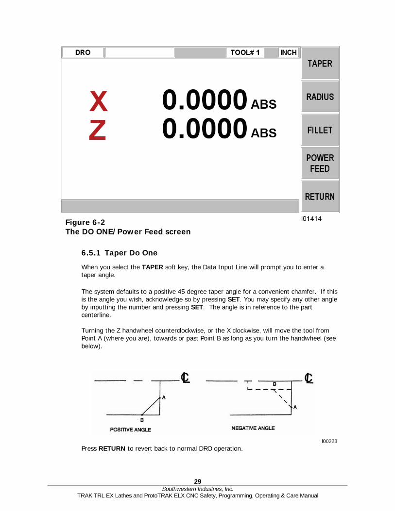
6.5.1 Taper Do One
When you select the TAPER soft key, the Data Input Line will prompt you to enter a taper angle.
The system defaults to a positive 45 degree taper angle for a convenient chamfer. If this is the angle you wish, acknowledge so by pressing SET. You may specify any other angle by inputting the number and pressing SET. The angle is in reference to the part centerline. Turning the Z handwheel counterclockwise, or the X clockwise, will move the tool from Point A (where you are), towards or past Point B as long as you turn the handwheel (see below).
i00223 Press RETURN to revert back to normal DRO operation.
Figure 6-2 The DO ONE/Power Feed screen

30 Southwestern Industries, Inc.
TRAK TRL EX Lathes and ProtoTRAK ELX CNC Safety, Programming, Operating & Care Manual
6.5.2 Radius Do One
When you select the RADIUS soft key, the Data Input Line will prompt you to enter a radius value. Input and SET the radius you want through the keyboard. The radius may be positive or negative. Turning the Z handwheel counterclockwise, or the X clockwise will move the tool from Point A (where you are), towards Point B (see below). The tool will automatically stop when you reach B.
Press RETURN to revert back to normal DRO operation.
6.5.3 Fillet Do One
When you select the FILLET soft key, the Data Input Line will prompt you to enter a radius value. Input and SET the fillet radius you want through the keyboard. The radius may be positive or negative.
Turning the Z handwheel counterclockwise, or the X clockwise will move the tool from Point A (where you are), towards Point B (see below). The tool will automatically stop when you reach B.
Press RETURN to revert back to normal DRO operation.
6.5.4 Power Feed
The servomotors can be used as a power feed for the carriage or cross slide, or both simultaneously. The door must be closed to run a power feed move.
a. Press the POWER FEED soft key.
i00224
i00225
31 Southwestern Industries, Inc.
TRAK TRL EX Lathes and ProtoTRAK ELX CNC Safety, Programming, Operating & Care Manual
b. A message box will appear that shows the power feed dimensions. All power feed moves are entered as incremental moves from the current position to the next position.
c. Enter a position by pressing the axis key, the distance to go and the +/- key (if needed). Input the entry by pressing INC SET. For example, if you wanted to make a power feed move of 2.00" of the cross slide in the negative direction, you would enter: X, 2, +/-, INC SET.
d. Initiate the power feed move by pressing GO.
e. The feedrate is automatically set to 10 ipm (or 254 mm per min). To power feed in IPR, press the IPR soft key. This key will toggle between IPM and IPR. Press or to adjust the feedrate.
f. Press STOP to halt power feed. Press GO to resume.
g. Repeat the process beginning at "c" above as often as you wish.
h. Press RETURN soft key to return to manual DRO operation.
6.6 Go To The Go To function in the DRO mode allows you to set a dimension in X or Z at which you want the machine to stop moving when you are cranking manually. For example, if you wanted to machine manually exactly 2" of carriage motion, you would input: Go To, Z, 2, Inc Set. While the Go To window is displayed, the ProtoTRAK SLX CNC will not let you pass that 2" dimension you set.
a. Press the Go To key.
b. Enter the axis X or Z or a combination of both.
c. Press Inc Set or Abs Set.
d. Crank the handwheel. Motion will stop at the entered dimension even if you continue to crank the handwheel.
6.7 Return Home
At any time during manual DRO operation you may automatically move the tool tip to your home location in X and Z by pressing the RETURN HOME soft key. When you do, the conversation line will read "Check Tool then press GO." Make sure your tool and its path is clear and the door is closed. Press the GO key. When you do, the carriage and cross slide will move at rapid speed to your X and Z home position. Home position is established in the Set-Up Mode.
6.8 Tool # The ProtoTRAK ELX CNC allows you to use the offsets for tools in your Tool Table (see Section 10.5) in the DRO Mode. To change tools, press the TOOL # soft key and enter the tool number when prompted by the Data Input Line.
If you do not wish to use the tools in the Tool Table, simply ignore the Tool # feature.

32 Southwestern Industries, Inc.
TRAK TRL EX Lathes and ProtoTRAK ELX CNC Safety, Programming, Operating & Care Manual
6.9 Tool Tip Radius Compensation in DRO Mode The tool tip radius is not important when you are turning along the side of a part (moving only Z), or along the face (moving only X). And in manual operation in the DRO Mode, these are the only motions that you can do. It's just not possible to move X and Z simultaneously with both hands along a precisely coordinated path. Therefore, even if your tool has a radius, the DRO will display point X0, Z0 in the figure in Section 5.4. In other words, it will display the X and Z contact line positions, which is where the tool will cut when you move either of the handwheels.
In Do One operation the tool is moved simultaneously in both the X and Z axes, but the readout still refers to point X0, Z0 in the figure in Section 5.4. This theoretical point will be driven through the taper or radius. As a consequence, if the tool tip radius is large, you may not machine the exact dimension you expect. These errors will generally be insignificant and can be eliminated all together by using a full program (see Section 7.0).
.
33 Southwestern Industries, Inc.
TRAK TRL EX Lathes and ProtoTRAK ELX CNC Safety, Programming, Operating & Care Manual
7.0 Program Mode The ProtoTRAK ELX can be easily programmed to for a wide variety of parts in two axes. A program is one or a series of events. It can either be a complete part, a set of operations on a side or only a small number of cuts. It is necessary to create a program when you want the CNC to machine the part for you.
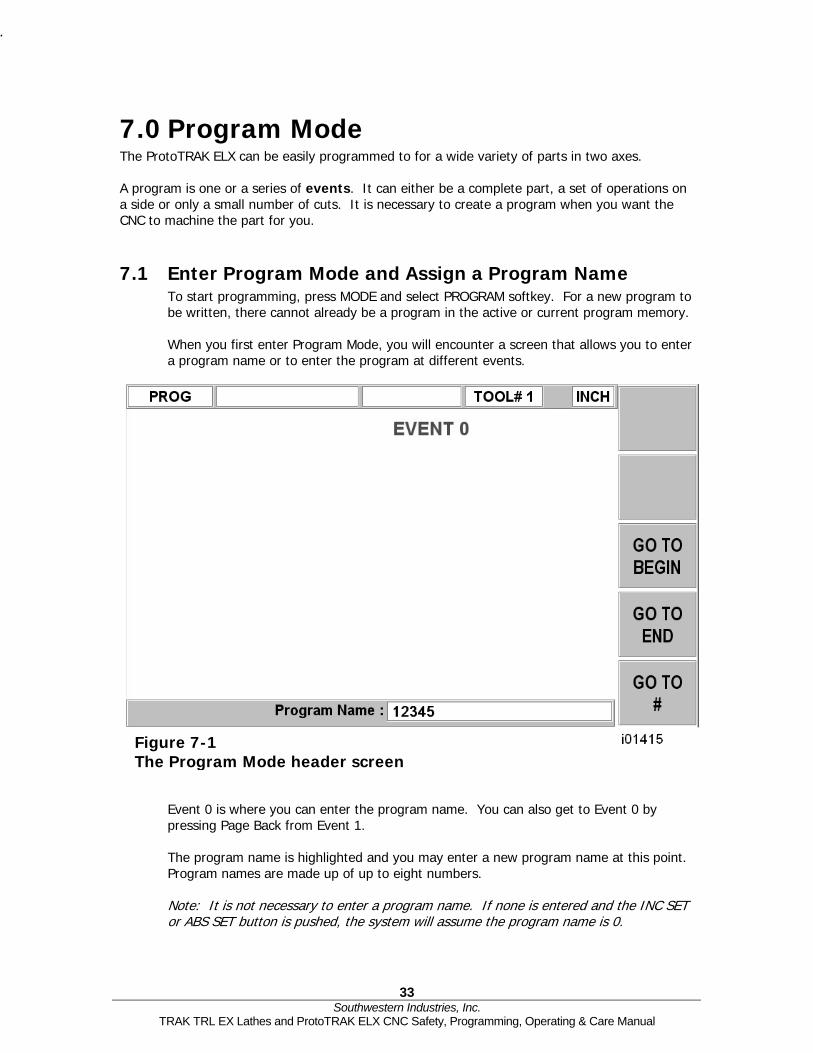
7.1 Enter Program Mode and Assign a Program Name To start programming, press MODE and select PROGRAM softkey. For a new program to be written, there cannot already be a program in the active or current program memory. When you first enter Program Mode, you will encounter a screen that allows you to enter a program name or to enter the program at different events.
Event 0 is where you can enter the program name. You can also get to Event 0 by pressing Page Back from Event 1. The program name is highlighted and you may enter a new program name at this point. Program names are made up of up to eight numbers. Note: It is not necessary to enter a program name. If none is entered and the INC SET or ABS SET button is pushed, the system will assume the program name is 0.
Figure 7-1 The Program Mode header screen

.
34 Southwestern Industries, Inc.
TRAK TRL EX Lathes and ProtoTRAK ELX CNC Safety, Programming, Operating & Care Manual
The ProtoTRAK ELX automatically holds all of the completed events as you program in current memory. Choices at the beginning of Program Mode:
GO TO BEGIN: puts Event 0 on the left side of the screen and the first event on the right side.
GO TO END: puts the last programmed event on the left side of the screen and the next event to be programmed on the right side.
GO TO #: enter the event number you wish to go to and then press SET. This puts the requested event number on the right side of the screen and the previous event number on the left.
Note: for a new program that has no Events, all the GO TO selections will take you to the beginning, with Event 0 on the left and the Select an Event options for Event 1 on the right.
7.2 Programming Strategy and Procedures The ProtoTRAK ELX makes programming easy by allowing you to program the actual part geometry as defined by the print. The basic strategy is to select the softkey event type (geometry) and then follow all instructions in the conversation line. When an event is selected, all the prompts will be shown on the right side of the information area. The first prompt will be highlighted and also shown in the conversation line. Input the dimension or data requested and press INC SET or ABS SET. For X or Y dimension data it is very important to properly select INC SET or ABS SET. For all other data either SET will do.
As data is being entered it will show in the conversation line. If you make a mistake, for example, you press the wrong number key, you can clear the input by pressing RESTORE. When SET, the data will be transferred to the information area, and the next prompt will be shown in the conversation line. From the event data screen you may press the up arrow key to the upper right of the LCD screen to go back to edit any data within an event.
Options within an event include:
PAGE FWD: moves forward through the programmed events.
PAGE BACK: moves backwards through the programmed events.
INSERT EVENT: use this to insert a new event into the program. This new event will take the place of the one that was on the right side of the screen when you pressed the INSERT EVENT key. That previous event, and all the events that follow, increase their event number by one. For example, if you started with a program of four events, if you were to press the INSERT EVENT key while Event 3 was on the right side of the screen, the previous Event 3 would become Event 4 and the previous Event 4 would become Event 5. If you insert a Repeat event, the event numbers will increase by one as when you insert another kind of event.
DELETE EVENT: this will delete the event on the right side of the screen.

.
35 Southwestern Industries, Inc.
TRAK TRL EX Lathes and ProtoTRAK ELX CNC Safety, Programming, Operating & Care Manual
ARROW KEYS: they move the cursor up and down within an event and back to a previous event if at the end of the program.
When all data for an event has been entered, the entire event will be shifted to the left side of the screen and the conversation line will ask you to select the next event.
7.3 Programming Events Events are fully defined pieces of geometry. By programming events, you tell the ProtoTRAK ELX what geometry you want to end up with; it figures the tool path for you from your answers to the prompts and the tool information you give it in the Set-Up Mode.
Figure 7-2 Programming Events screen #1

.
36 Southwestern Industries, Inc.
TRAK TRL EX Lathes and ProtoTRAK ELX CNC Safety, Programming, Operating & Care Manual
7.3.1 Position Events This event type positions the tool at a specified position. The positioning is always at rapid speed (modified by feedrate override) and in the most direct path possible from the previous location. Position is most often used to move the tool away from the part so that when it rapids to a next non-connective event or home, it will not crash into the workpiece.
To program a Position event press the POSN soft key.
Prompts for the Position event:
X: is the X dimension (diameter).
Z: is the Z dimension.
CONTINUE: asks you if you wish to continue on to the next event (press 1, SET), or pause after the tool is at position (press 0, SET).
TOOL#: is the tool number you assign from 1-99.
7.3.2 DRILL/BORE Events
First choose DRILL or BORE from the soft key options.
DRILL
This event allows you to drill a hole at the centerline of the part (X = 0 ABS) using the carriage and cross slide.
Figure 7-3 Programming Events screen #2

.
37 Southwestern Industries, Inc.
TRAK TRL EX Lathes and ProtoTRAK ELX CNC Safety, Programming, Operating & Care Manual
The event tool motion will be to rapid in a straight line to X = 0 ABS and the programmed Z RAPID position, then feed the programmed number of pecks to Z END, then rapid out to Z RAPID. The drill will also come out to Z Rapid after each peck.
Prompts for the Drill Event:
Z RAPID: is the Z dimension to transition from rapid to feed.
Z END: is the Z depth of the hole.
FEEDRATE: Enter 0.1 to 250 ipm or 2.5 – 6350 mm/min and press SET.
# PECKS: is the number of tool withdrawal cycles. Each cycle drills and then retracts to the Z rapid position. Each peck is successively smaller, taking the largest cuts at the beginning and the smallest at the end.
TOOL#: is the tool number you assign from 1-99.
BORE
This event allows you to bore a part using a standard boring bar.
The event tool motion will be to rapid in a straight line to the programmed X dimension, the programmed Z RAPID position, then feed to Z FINAL, then feed .01 inch towards the centerline in X to clear the tool from the part, then rapid out to Z RAPID.
Prompts for the Bore Event:
X: is the diameter of the bore.
Z RAPID: is the Z dimension to transition from rapid to feed.
Z FINAL: is the Z depth of the bore.
FEEDRATE: Enter 0.1 to 250 ipm or 2.5 – 6350 mm/min and press SET.
TOOL#: is the tool number you assign from 1-99.
7.3.3 Turn Events
This event allows you to turn in a straight line from any one XZ point to another, including an inside or outside taper. This event should be used for facing since this is also a straight line move from one XZ point to another. The event may be programmed with a CHAMFER or CONRAD if it is connective with the next event.
The event tool motion will be to rapid to the X BEGIN, Z BEGIN position, then feed to X END, Z END with consideration for CHAMFER or CONRAD if one is programmed.
Prompts for the Turn Event:
X BEGIN: is the X dimension to the beginning of the cut (diameter).
Z BEGIN: is the Z dimension to the beginning of the cut.
X END: is the X dimension to the end of the cut; incremental is from X Begin.
Z END: is the Z dimension to the end of the cut; incremental is from Z Begin.
CHAMFER/CONRAD: is the dimension of a chamfer or tangential radius to the next event. Use ABS SET for chamfer, or INC SET for conrad.
TOOL OFFSET: is the selection of the tool offset to right (input 1), offset to left (input 2), or tool center--no offset (input 0) relative to the programmed edge and direction of tool cutter movement (see Section 5.5).

.
38 Southwestern Industries, Inc.
TRAK TRL EX Lathes and ProtoTRAK ELX CNC Safety, Programming, Operating & Care Manual
FEEDRATE: Enter 0.1 to 250 ipm or 2.5 – 6350 mm/min and press SET.
TOOL #: is the tool number you assign from 1-99.
7.3.4 ARC Events
This event allows you to turn with circular contouring any arc (fraction of a circle).
The event tool motion will be to rapid to the X Begin, Z Begin position, then feed to X End, Z End in a circular path.
Prompts for the Arc Event:
X BEGIN: is the X dimension to the beginning of the arc cut (diameter).
Z BEGIN: is the Z dimension to the beginning of the arc cut.
X END: is the X dimension to the end of the arc cut; incremental is from X Begin.
Z END: is the Z dimension to the end of the arc cut; incremental is from Z Begin.
RADIUS: is the radius of the arc, measuring up to 800 inches (not measured in diameter).
CHAMFER/CONRAD: is the dimension of a chamfer or tangential radius to the next event. Use ABS SET for a chamfer, or INC SET for conrad.
DIRECTION: is the clockwise (input 1), or counterclockwise (input 2) direction of the arc looking down from the top.
TOOL OFFSET: is the selection of the tool offset to right (input 1), offset to left (input 2), or tool center--no offset (input 0) relative to the programmed edge and direction of tool cutter movement (see Section 5.5).
FEEDRATE: Enter 0.1 to 250 ipm or 2.5 – 6350 mm/min and press SET.
TOOL #: is the tool number you assign from 1-99.
7.3.5 Cycle Events
The Cycle Event is not a single event, but rather a group of Turn and Arc events. It allows you to program complex shapes (including the shape of the starting material) that require several roughing passes without the need to program each tool motion step.
i00226

.
39 Southwestern Industries, Inc.
TRAK TRL EX Lathes and ProtoTRAK ELX CNC Safety, Programming, Operating & Care Manual
Consider the part above that is being machined from a rough casting. Lines 1-6 represent the finished part, and lines 7-9 represent the casting, or something a little bigger than the casting.
You program this part by first defining the finished part, lines 1 through 6 as Cycle Turns and Cycle Arcs. Then you define the casting, lines 7 through 9, by programming Cycle Position events for the line end points. The Cycle must be closed. In this drawing, this means that line 9 must end where line 1 begins.
In the Cycle header screen, you program how you want the entire sequence to be machined. One of the choices you make is whether you want the roughing passes to be
in the X axis or the Z axis. For that reason, it is necessary that all features of the part must be entirely visible either in the X axis or Z axis. The following examples illustrate this. In order to understand the rule, forget for a moment any consideration of what kind of tool you would have to use to cut the part.
In the drawing to the left, not all of the features of the part are visible in either the X or Z axis. Looking at the part in the X view, line segments 1 through 3 are
not visible. Looking at the part from the Z view, line segments 6, 7 and part of 8 are not visible. Since the part must be completely visible in one view or the other, this part cannot be machined with one cycle. The Z view may also be from the other direction, looking from the chuck. And the X view can also be from looking out from the centerline for ID turning.
The solution to this part is simple. Divide the part into two Cycles, one cycle to machine segments 1 through 4 and one to machine segments 5 through 8.
The tool motion in Cycle depends on whether you select to rough the material with successive turning passes (Z motion with constant X), or facing passes (X motion with constant Z). If you choose turning (approach = Z), the tool will rapid to a point at the programmed material. Then the tool will feed at a constant X position across until it nears one of the part lines leaving enough material for the programmed finish cut. This is repeated until the part is completely roughed. Then the tool will feed along the part lines standing off an amount equal to the finish cut. Then the carriage will move to home and call out the finish tool. This tool will rapid to the beginning of the first line and turn the part to its final dimension.
There are times where you have already completed the roughing passes and wish to go over the finish pass again – for example, after a tool modifier is entered. In the Run Mode, select the START EVENT # soft key and enter the event number of the Cycle header event. You will have the choice of starting at the roughing or finishing pass.

.
40 Southwestern Industries, Inc.
TRAK TRL EX Lathes and ProtoTRAK ELX CNC Safety, Programming, Operating & Care Manual
The Cycle Event Prompts:
X BEG: the X dimension to the beginning of the cycle.
Z BEG: the Z dimension to the beginning of the cycle.
# PASSES: is the number of roughing passes the 1440 will take.
APPROACH: is to select if the roughing is to be done along X with facing passes (input 0, SET), or along Z with turning passes (input 1, SET).
FEEDRATE: Enter 0.1 to 250 ipm or 2.5 to 6350 mm/min and press SET.
TOOL #: is the number you assign to the roughing tool.
FIN CUT: is the depth of the final finish cut made with the finish tool.
FIN FEEDRATE: Enter 0.1 to 250 ipm or 2.5 – 6350 mm/min and press SET.
FIN TOOL #: is the number you assign to the finishing tool.
WARNING!
When loading a cycle program from a ProtoTRAK SLX that uses depth per pass within the cycle, the program will need to be modified to add the # of passes you want to cut the cycle.
When the screen is complete, the ProtoTRAK ELX CNC will prompt you to input a series of TURN, ARC and POSITION events to describe the part and the original material.
The first screen will have the soft keys:
Figure 7-4 Cycle Event Screen #1

.
41 Southwestern Industries, Inc.
TRAK TRL EX Lathes and ProtoTRAK ELX CNC Safety, Programming, Operating & Care Manual
Where you would continue to define the finished part with CYCLE TURN and CYCLE ARC events. Follow this by defining the shape of the original material with CYCLE POSITION events. When the last CYCLE POSITION event is defined it must end where the first cycle event began. Press the END CYCLE soft key to end the cycle event.
If the last CYCLE POSITION event does not end at the beginning of the first cycle event, the system will prompt you that the cycle is not “Closed” and ask for a YES or NO response. If YES is selected, the system will automatically enter a closing CYCLE POSITION event. If NO is selected, you may enter your own closing CYCLE POSITION event(s).
LOOK may be used to view the completed cycle event without each tool pass displayed. Use TOOL PATH to display all tool passes. Special care must be taken with tool set-up and the Cycle routine, especially when doing back cuts. When we designed the Cycle, we had to make a choice. The way other CNCs handle the tooling issue is to force the operator to define the tool that he is using very thoroughly. Instead of the few simple inputs required to set up the tools in the ProtoTRAK, they require you to put in several more dimensions – all so the CNC can determine whether or not the tool will do the programmed move without crashing. Keep in mind that the other CNC doesn't do anything to help you set the tools up, it just requires you to tell it a lot of information so that it can generate an error message. Rather than add this complication to our CNC, we chose to give you the capability to do the back cuts, and leave it to you to judge for yourself whether or not the tool will fit. Getting the right tool set-up is the same with either approach. With the ProtoTRAK, you don’t have to deal with the complication of telling the CNC a lot more data.
Figure 7-5 Cycle Event Screen #2

.
42 Southwestern Industries, Inc.
TRAK TRL EX Lathes and ProtoTRAK ELX CNC Safety, Programming, Operating & Care Manual
7.3.6 Thread Event
This event allows you to machine standard or custom I.D. or O.D. threads. They may be straight or tapered.
The event tool motion will be to rapid to the X MAJOR BEGIN, Z BEGIN position, then feed to a depth equal to the total thread depth adjusted for the number of passes, then feed to X MAJOR END, Z END, then rapid away from the thread by 0.050”, then return to X MAJOR BEGIN, Z BEGIN and repeat for the total number of passes. The depth of each pass is calculated to remove an equal volume of material.
The Thread Event Prompts:
X MAJOR BEGIN: is the X dimension or major diameter where the thread begins
Note: ID threads are also programmed using the major diameter.
Z BEGIN: is the Z dimension where the thread begins.
X MINOR BEGIN: For a standard thread, input 0, ABS SET for the X MINOR BEGIN. Otherwise, you may input a custom minor diameter for your thread.
X MAJOR END: is the X dimension or major diameter when the thread will end.
Z END: is the Z dimension where the thread ends. PITCH: is the distance from one thread crest to the next in inches or mm. It is equal to one divided by the number of threads per inch. For example, the pitch for a 1/4-20 screw is 1 divided by 20 = .05 inches.
# PASSES: is the number of passes (1-99) to cut the thread to its final depth (excludes spring passes).
Figure 7-6 Thread Event

.
43 Southwestern Industries, Inc.
TRAK TRL EX Lathes and ProtoTRAK ELX CNC Safety, Programming, Operating & Care Manual
SPRING PASSES: is the number of passes (0-99) at the final depth.
PLUNGE ANGLE: is the angle the tool feeds into the beginning depth. The default 29.5 degrees is recommended.
SIDE: selects whether this is an I.D. (input 1, SET), or O.D. (input 2, SET) thread.
TOOL #: is the tool number you assign from 1-99.
Note: The ProtoTRAK ELX supports both standard and custom threads when opening either an LX2 or CAM file. However, if a standard thread is created on another machine type and opened on the ELX, the control will open it and not display the X MINOR DIAMETER, nor will it be editable, since the data is missing. The program will still run correctly. If you wish to create a custom thread, simply create a new thread event and the option will be there.
7.3.7 Repeat Events
The Repeat event allows you to repeat an event or a group of events up to 99 times with an offset in X and/or Z. This can be useful for a simple roughing cycle (and where a full CYCLE event is inappropriate) at increasing depths. It is also very useful in programming rough and finish events without having to worry about adjusting the dimensions for the finish cut (see Section 7.3.8).
Prompts for the Repeat Event:
FIRST EVENT #: is the event number of the first event to be repeated.
LAST EVENT #: is the event number of the last event to be repeated; if only one event is to be repeated, the Last Event # is the same as the First Event #.
X OFFSET: is the incremental X offset from event to be repeated (diameter).
Z OFFSET: is the incremental Z offset from event to be repeated.
# REPEATS: is the number of times events are to be repeated up to 99.
TOOL #: is the tool number you assign from 1-99.
7.3.8 Finish Cuts
The Cycle event is designed with a built-in finish cut routine. You may, however, want to program a roughing cut and a finish cut on a part which has been defined by BORE, TURN, and ARC events.
The hard way to do this is to adjust all the X and Z dimensions (this is especially tricky for arcs) for the roughing cut, then program the correct part dimensions for the finish cut.
The easy way is to use the following technique:
a. Program the actual part shape and ignore the need to leave material for a finish cut.
b. Use one Repeat event to repeat all the events in "a" above, but call out a different tool number even if you are actually using the same tool.
c. In Set-Up Mode input an XMOD and ZMOD for the tool in the events programmed in "a" above that is equal to the finish cut material you wish to leave. See Section 9.0 for how to input this data.

.
44 Southwestern Industries, Inc.
TRAK TRL EX Lathes and ProtoTRAK ELX CNC Safety, Programming, Operating & Care Manual
d. In Set-Up Mode make NO special adjustment to XMOD or ZMOD for the tool programmed in the Repeat event in "b" above.
When the part is being run the XMOD and ZMOD from "c" will command the tool to stay away by this amount when the events from "a" are machined. However, when these events are repeated from "b", the correct dimensions will be cut on the part.

45 Southwestern Industries, Inc.
TRAK TRL EX Lathes and ProtoTRAK ELX CNC Safety, Programming, Operating & Care Manual
8.0 Changing or Correcting Programs In the Program Mode, you can easily correct mistakes or make changes to the program.
8.1 Deleting a Partially Programmed Event If you wish to not program an event (or start over) after you have started to program, press the DELETE EVENT softkey and the screen will revert to the "Select Event" prompt.
8.2 Editing Data while Programming an Event All data is entered by pressing the appropriate numeric keys and pressing INC SET or ABS SET. If you enter an incorrect number before you press INC SET or ABS SET you may clear the number by pressing RESTORE. Then, input the correct number and press SET. If incorrect data has been entered and SET, you may correct it as you are still programming that same event by pressing the arrow up or arrow down keys to the right of the LCD screen until the incorrect data is highlighted and shown in the conversation line. Enter the correct number and SET. The ProtoTRAK EMX will not allow you to skip past prompts (by pressing an arrow key) that need to be entered to complete an event.
8.3 Editing Previously Programmed Events From the Select Event screen you may press the arrow up key to the right of the LCD screen and the program will move back one event. From that point, you will have the following softkey options: INSERT EVENT allows you to insert a new event between the two shown on the left and right side of the screen. When you press INSERT EVENT the screen will revert to the Select Event screen and you may program the new added event as you would any other. Subsequent events will be renumbered accordingly. DELETE EVENT allows you to delete the event on the right side of the screen. Subsequent events will be renumbered accordingly. ARROW KEYS allow you to move the cursor up and down within the event. PAGE FWD (Forward) indexes the event forward by one. PAGE BACK indexes the event back by one.
8.4 Changing the Feedrate If the feedrate is edited in any event it will automatically be edited in every subsequent and contiguous event with the same tool number and feedrate. For example, let’s say events 5 through 10, and 13 through 16 were all programmed with tool number 2, and 5 inches per minute feedrate. If you edit the feedrate in Event 7 to 3 inches per minute, it will automatically change Events 8, 9, and 10 also. Events 5, 6, 13, 14, 15, and 16 will not be affected
48 Southwestern Industries, Inc.
TRAK TRL EX Lathes and ProtoTRAK ELX CNC Safety, Programming, Operating & Care Manual
8.5 Changing a Part Number (making a copy of a program) You may want to rename a part program, or make a copy of a program using a different name. The latter may be useful if you have a new part to do that is similar to a part that you already have programmed. Make a copy of the program by saving it under a new part number and then make the changes.
You can rename a part program in three ways:
- Press the PAGE BACK key past the first event until you are at Event 0 and the
prompt for Program Part Number. Enter the new part number and press SET. - Exit the Program Mode by pressing Mode and then re-enter it. You will have an
opportunity to rename it then. - Rename it in the Program In/Out Mode. After pressing the PROG IN/OUT key,
simply enter the new part number and press SAVE. If the previous part program is already stored on the system internal storage it will remain in storage under the previous part number with the same information it had the last time it was stored.
8.6 Saving Changes to a Program If a program is opened from storage and changes are made, the program must be stored again in Prog In/Out Mode for the changes to be preserved in the stored copy. Programs in current memory may be changed and run with the changes, but unless they are saved again, the changes made will be lost when the program is cleared from current memory. If you intend to keep the changes made to your program it is a good practice to store the program occasionally in case a power loss causes the program to be ejected from current memory.
8.7 Erasing an Entire Program To erase an entire program from current memory, go to the Program In/Out Mode and press ERASE PROG. You will be prompted "Are you sure you want to erase this program?" You may want to store the program before you clear it from current memory. If it is not stored, pressing YES will permanently erase the program. To erase an entire program from the internal storage, input the part number and then press DELETE. Programs in current memory will not be affected by this operation. You could erase a part number on the internal storage and the program in current memory will remain in current memory, even if it has the same part number as the one just erased. Programs in current memory will automatically be erased when another program is retrieved from storage.
49 Southwestern Industries, Inc.
TRAK TRL EX Lathes and ProtoTRAK ELX CNC Safety, Programming, Operating & Care Manual
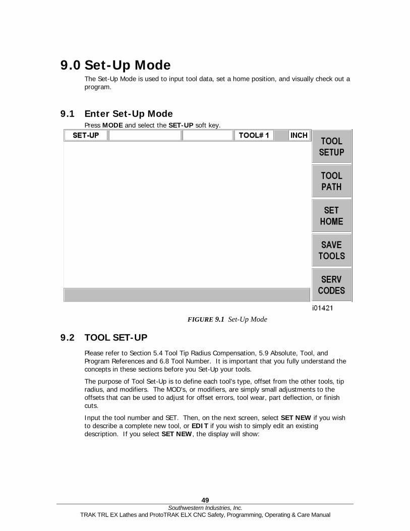
9.0 Set-Up Mode The Set-Up Mode is used to input tool data, set a home position, and visually check out a program.
9.1 Enter Set-Up Mode Press MODE and select the SET-UP soft key.
FIGURE 9.1 Set-Up Mode
9.2 TOOL SET-UP Please refer to Section 5.4 Tool Tip Radius Compensation, 5.9 Absolute, Tool, and Program References and 6.8 Tool Number. It is important that you fully understand the concepts in these sections before you Set-Up your tools.
The purpose of Tool Set-Up is to define each tool's type, offset from the other tools, tip radius, and modifiers. The MOD's, or modifiers, are simply small adjustments to the offsets that can be used to adjust for offset errors, tool wear, part deflection, or finish cuts.
Input the tool number and SET. Then, on the next screen, select SET NEW if you wish to describe a complete new tool, or EDIT if you wish to simply edit an existing description. If you select SET NEW, the display will show:

50 Southwestern Industries, Inc.
TRAK TRL EX Lathes and ProtoTRAK ELX CNC Safety, Programming, Operating & Care Manual
Input the tool type 1 through 9 and SET. If, for example, you chose 1 (the right-hand turn/face tool) the display would show:
Figure 9-2 Tool Selection Screen
Figure 9-3 Tool Set-up Screen

51 Southwestern Industries, Inc.
TRAK TRL EX Lathes and ProtoTRAK ELX CNC Safety, Programming, Operating & Care Manual
Where: X: will prompt "move to known X value, input and SET" which means, touch the tool to some known reference at SET X in the picture on the left side of the screen, then input this reference X dimension and SET.
Z: will prompt "Move to known Z value, input and set" which means, touch the tool to some known reference at SET Z in the picture on the left side of the screen, then input this reference Z dimension and SET.
RADIUS: is to define the tool nose radius.
X MODIFIER: is to input an adjustment or modifier to the X offset. A positive X MOD will make the part O.D. or I.D. diameter larger by this amount.
Z MODIFIER: is to input an adjustment or modifier to the Z offset. A positive Z MOD will shift the part away from the chuck.
Repeat the above procedure for all of the tools.
9.2.1 Practical Technique for Accurate Tool Setting
The problem with setting tools as described in Section 92 above is that it is generally not possible to touch a tool off with high precision. Furthermore, under real cutting conditions the tool, part and machine deflect a little so that what you move and what you cut are not exactly the same.
If the parts you are machining require a high level of accuracy you should do the following:
a. Set the tools as described in Section 92.
b. Machine a test part that is as similar to your part as possible—same material, shape, etc.
c. Measure the test part carefully noting which tool cut which dimension.
d. Input X and Z modifiers that will maximize the parts accuracy.
9.2.2 Tool Set-Up When Adding or Changing Tools For tool setting, it is absolutely necessary for every tool to be set with the same absolute reference. Therefore, if you add a new tool, or reset an existing one, you must be certain that your absolute reference is correct for the existing tools. Follow this procedure:
a. Load one of the existing tools. b. Enter DRO Mode and call out the above Tool #. c. Touch off the side of a known diameter and X preset it in absolute. d. Touch off the end of a part or the chuck and Z preset it in absolute.
CAUTION! The objective of Tool Set-Up is to establish the position of each tool relative to the others. To do this, the procedure must be conducted with one common counting or absolute reference. That is, between setting one tool and the next it is crucial that you do not go back into the DRO mode and change the absolute reference. If this happens, see Section 92.2

52 Southwestern Industries, Inc.
TRAK TRL EX Lathes and ProtoTRAK ELX CNC Safety, Programming, Operating & Care Manual
e. Load the new tool. f. Set the new tool as you would in Section 92 measuring X diameter as you
normally would, and measuring Z from the same position as "d" above.
9.3 TOOL PATH When the TOOL PATH soft key is pressed, the program is processed and the tool path graphics are displayed.
FIGURE 10.3 The Tool Path graphics show the program and tool positions Most programming errors that would prevent the program from running are detected when the tool path graphics are selected.
The displayed graphic is automatically sized to fit the screen and an icon that represents the X and Z orientation is placed at the program's absolute 0 reference point. The path shown on the screen represents the center of the tool.
Colors provide information about the tool path:
• Position and drill events are drawn in yellow. • Rapid moves are in red. • Programmed geometry is in blue.
9.3.1 Soft Keys in Tool Path
FIT: will re-draw, automatically sizing to fit the screen (necessary only if an adjustment changed the drawing from its initial sizing).
STEP: each press of the STEP button shows the next tool move. To complete the drawing automatically, press FIT DRAW.
9.4 SET HOME The SET HOME screen shows the home locations for the X and Z axes.
9.4.1 Home Positions
X and Z home positions are where the cross slide and carriage go when there is a tool change or at the end of the program. This is relative to the tool tip for the displayed tool number. These dimensions must always be from absolute zero.

53 Southwestern Industries, Inc.
TRAK TRL EX Lathes and ProtoTRAK ELX CNC Safety, Programming, Operating & Care Manual
9.5 SAVE TOOLS Tool types, offsets, radii, and modifiers are not saved with the program (see Section 9 for Program In/Out). To save this data, press the SAVE TOOLS softkey from the SET-UP MODE screen.
WARNING! If you turn the ProtoTRAK SLX CNC off (or if you lose power) and you have not saved your
tools, all of your tool data will be lost! It is a good habit to do a simple SAVE TOOLS after you have made any tool additions or changes.
WARNING! For any one tool number, only one set of tool data may exist at any time. When you do a SAVE
TOOLS, the data for each tool number will be updated and the previous data (if different) will be lost.
9.6 SERV CODES Service codes are special codes used for set-up, installation, or program file transfer
Code Description Notes 12 Determine feed forward
constant Runs a routine that determines the system friction for setting feed forward constant. Caution! Do not use this code unless you understand the consequences. See SWI Publication No. 26008 "ProtoTRAK ELX Installation and Service Manual."
22 Turn on simulation For demo purposes, the ProtoTRAK EMX may be run in simulation mode where the control operates normally but does not send commands to the motors. If you use this code, don't forget to restore your CNC to normal operation with Service Code 89! Simulation mode is also cancelled by turning the control on and off.
33 Software ID Displays the version of software your ProtoTRAK EMX is using.
54 Continuous run mode Keeps running the system through the program without stopping. It is used for testing.
66 Metric mode To have the ProtoTRAK EMX power up in Metric measurement.
67 Inch mode To have the ProtoTRAK EMX power up in Inch measurement.
79 Turn on beeper Factory setting. 80 Turn off beeper For stealthy machining. 81 Keyboard test For testing the front panel buttons. 89 Cancel simulation Cancel the Service Code 22 simulation. 97 Axis configuration To orient the motor encoder. This should not
need to be done except in a service situation. 100 Axis open loop test Runs selected axis at rapid for one second and
displays values. Caution! The machine will move. Be sure you understand the consequences before you use this code. See SWI Publication No. 26008 "ProtoTRAK ELX Installation and Service Manual."

54 Southwestern Industries, Inc.
TRAK TRL EX Lathes and ProtoTRAK ELX CNC Safety, Programming, Operating & Care Manual
123 Calibration of each axis of measurement.
See SWI Publication No. 26008 "ProtoTRAK ELX Installation and Service Manual."
125 Display calibration factors See SWI Publication No. 26008 "ProtoTRAK ELX Installation and Service Manual."
127 Single encoder backlash calibration
Used to calculate a backlash value for entering in Code 128. See SWI Publication No. 26008 "ProtoTRAK ELX Installation and Service Manual."
128 Enter backlash value Used to enter the backlash value calculated using Code 127. See SWI Publication No. 26008 "ProtoTRAK ELX Installation and Service Manual."
131 Manual DRO See SWI Publication No. 26008 "ProtoTRAK ELX Installation and Service Manual."
132 Electronic Handwheel Test See SWI Publication No. 26008 "ProtoTRAK ELX Installation and Service Manual."
133 Spindle Encoder Test See SWI Publication No. 26008 "ProtoTRAK ELX Installation and Service Manual."
141 Load parameters Will take parameters from USB thumb drive 142 Save control parameters Save parameters to the USB thumb drive. 308 Reverse X Handwheel
Direction See SWI Publication No. 26008 "ProtoTRAK ELX Installation and Service Manual."
310 Reverse Z Handwheel Direction
See SWI Publication No. 26008 "ProtoTRAK ELX Installation and Service Manual."
313 Display Configuration File See SWI Publication No. 26008 "ProtoTRAK ELX Installation and Service Manual."
316 Update software Used to update to the latest software version from the USB thumb drive.
319 Error Log See SWI Publication No. 26008 "ProtoTRAK ELX Installation and Service Manual."
320 History Log See SWI Publication No. 26008 "ProtoTRAK ELX Installation and Service Manual."
326 Look up MSG See SWI Publication No. 26008 "ProtoTRAK ELX Installation and Service Manual."
327 Check Memory and Compact Flash
See SWI Publication No. 26008 "ProtoTRAK ELX Installation and Service Manual."
329 Test Frontpanel Backlight See SWI Publication No. 26008 "ProtoTRAK ELX Installation and Service Manual."
332 Load Save Tool Table Used to save or load a tool table to or from a USB thumb drive.
340 Back up programs Copy all the programs on the internal storage to the USB thumb drive.
341 Load programs Copy all the programs on the USB thumb drive to the internal storage.
342 Toggle Test Light Indicator See SWI Publication No. 26008 "ProtoTRAK ELX Installation and Service Manual."
400 Update Foreign Language MLS Files

55 Southwestern Industries, Inc.
TRAK TRL EX Lathes and ProtoTRAK ELX CNC Safety, Programming, Operating & Care Manual
10.0 Run Mode You must have four things accomplished before entering run mode: 1. Write the actual program (see section 7.0)
2. Set up your tools (see section 9.0)
3. Set a home position (see section 9.4.1)
4. Establish position relationship between the part and tool (see section 9.1)
After these are completed, you may run your program.
10.1 Starting to Run Before running a part, you need to establish the position relationship between the part and tool. That is, you need to be certain that when the readout displays X=0 ABS and Z=0 ABS for any input tool, then that tool is at the program absolute zero of the part. To do this: a. Enter the DRO Mode.
b. Load a tool and call up its Tool #.
c. Load a part.
d. Move to a known position on the part.
e. ABS SET this position.
f. Enter Run Mode and begin Run by pressing the START soft key.
If you wish to start in the middle of a program, press the START EVENT # soft key, input the number of the first event you wish to run, and SET.

56 Southwestern Industries, Inc.
TRAK TRL EX Lathes and ProtoTRAK ELX CNC Safety, Programming, Operating & Care Manual
10.2 Program Run Press the Run Mode button. The screen should show:
When you have started, the carriage and the cross slide will move to the home position you designated in SET-UP MODE.
The screen will show:
Figure 10-1 Run Mode Screen #1

57 Southwestern Industries, Inc.
TRAK TRL EX Lathes and ProtoTRAK ELX CNC Safety, Programming, Operating & Care Manual
Where:
• The part number being run is shown in the status line.
• The current X, Z absolute positions are shown in the information area.
• The actual tool Feedrate is shown at the bottom of the information area.
The run procedure is very simple. Follow the instructions on the conversation line and proceed by pressing the GO key.
10.3 Door Position in Run Mode The door must be closed when the lathe is making a move that is not directed by you by turning the handwheel. If the door is not closed, a message will appear and the lathe will not operate until the door is closed.
In the Run mode, the door must be closed for the following moves:
• Rapid to Home position at the beginning of program Run (right after you press the START key).
• CNC run.
Figure 10-2 Run Mode Screen #2

58 Southwestern Industries, Inc.
TRAK TRL EX Lathes and ProtoTRAK ELX CNC Safety, Programming, Operating & Care Manual
10.4 Program Run Messages While in the Run Mode, clear instructions and prompts from the ELX CNC will tell you exactly what to do to run the program. These messages will appear in a green box in the middle of the screen.
When a tool change is required, the tool information entered in the Tool Table will appear in the green box.
10.5 Stop At any time, pressing the STOP key may halt the program. This freezes the program at that point. To continue, press the GO key.
10.6 Feedrate and Spindle Speed Override The run feedrate may be changed at any time by pressing the or keys. Each press increases or reduces the programmed feedrate, as well as rapid by 10%.
10.7 Threading Exceptions If you cut a thread and then wish to adjust the XMOD for a more precise thread, you may re-run the event without cross-threading the part. However, you may NOT change RPM from the first run to the next.
10.8 Data Errors Section 8 describes several rules that must be followed to successfully program a part. In addition, a program must make sense geometrically. Data errors will nearly always be detected when the ProtoTRAK ELX CNC runs through a program--either as a Trial Run or on an actual part run. They may also be detected in the Set- Up mode when using the Draw Part or Tool Path Graphics routines.
When a data error is encountered by the system, an error message will appear on the ProtoTRAK ELX CNC display. The message will help you identify the event that caused the error and makes a suggestion for fixing the error.
10.9 Fault Messages The ProtoTRAK performs a number of automatic checks or self-diagnostics on itself. If problems are found it will signal you through the display. A window will display "Fault __ __ __ __". The information area will display an explanation and suggested solution. Press the RETURN key to get back to the Select Mode screen.

59 Southwestern Industries, Inc.
TRAK TRL EX Lathes and ProtoTRAK ELX CNC Safety, Programming, Operating & Care Manual
11.0 Program In/Out Mode
11.1 Cautions About Opening and Deleting Programs Care must be taken to keep from losing a program you wish to keep. This can happen two ways. First, the ProtoTRAK ELX can only have one program at a time in current memory. Whenever a program is opened, it will erase any current program. Therefore, if your current program is one you want to keep, be certain to store it before you retrieve another program. Second, to store a program, it must have a part number so the ProtoTRAK ELX can find it when you want to open it. However, no two programs can have the same part number (how would the system decide which to retrieve?). Therefore, if you store a program with any particular part number, it will automatically erase any other program with that same part number. In both cases above the ProtoTRAK ELX will give you a warning before erasing or overwriting your program.
11.2 Program Formats and Labeling The ProtoTRAK family of products has its own unique programming system—one that organizes the program into events rather than codes and blocks. Programs written on a two-axis lathe control (such as the ProtoTRAK ELX) will have the extension .LX2. The .LX2 programs created by the ProtoTRAK ELX are compatible with those created on other ProtoTRAK two-axis CNCs, provided that the event types of the program are found in the control that is running the program.
11.3 Saving and Opening Programs from the ProtoTRAK ELX internal storage
Press MODE and select the PROG IN/OUT softkey.
• All part numbers in the ProtoTRAK ELX internal storage are listed in the Information Area.
• The part number of the current program (in current memory) is shown in the conversation line. You may change the part number at this screen by entering a new number and pressing SAVE.
• OPEN will write a program from the internal storage to current memory. First input the part number and then press the OPEN key. Then you will have the option of either opening as an LX2 or CAM file type. For more on CAM files and G-Code see section 11.5.
• SAVE will write the program in current memory to the internal storage. You will see the program added to the list in the information area after it is stored.
• DELETE will erase a program from the internal storage. First input the program number and then press the DELETE key.
• ERASE PROG will erase the program from current memory. You do this to clear current memory in order to write a new program.
• The PAGE FWD (Forward) softkey will continue the part number list if there are too many to be shown on the screen.

60 Southwestern Industries, Inc.
TRAK TRL EX Lathes and ProtoTRAK ELX CNC Safety, Programming, Operating & Care Manual
11.4 File Transfer and Backup A USB port is provided and an optional USB Thumb drive offered as a convenient way to transfer and backup part programs. If you buy the optional thumb drive from Southwestern Industries, it will already be configured correctly. If you get your own thumb drive, please read the following: • The list of thumb drives that will work with this control are:
o PNY o Memorex o Lexar o Microadvantage o Delkin / E Film
• Before you can transfer programs from the thumb drive to the ProtoTRAK ELX, you must put the files in a folder named “Programs”.
To move files from the ProtoTRAK ELX internal storage to a thumb drive, do the following: 1. Plug the Thumb Drive into the ProtoTRAK ELX USB port. 2. Go to the DRO Mode. 3. Press Serv Codes. 4. Under group A, Software Service Codes, select code 341 “Copy Files from USB Drive to Control. 5. All the programs saved in the folder “Programs” on the thumb drive will also be saved on the
ProtoTRAK ELX internal storage. If there are programs with the same name in the destination location you will be asked by the ProtoTRAK ELX if you want to overwrite the existing file. Programs of different names on the destination location will not be affected. In keeping with our philosophy to make the ProtoTRAK ELX as simple as possible, we have elected the simplest possible program storage routines. File transfers between the ProtoTRAK ELX and thumb drive will move all programs between the two. This eliminates the complexity of adding file management to the ProtoTRAK ELX system. Files may be managed on the thumb drive with your offline computer.
11.5 CAM / G-Code files
The ProtoTRAK ELX allows you to open CAM / G-Code files and convert them into the ProtoTRAK ELX programming format. First you must transfer the programs into the ProtoTRAK’s internal memory as described in section 11.4. The filename must be numeric, no more than 8 digits long, and have a .CAM file extension. The supported G-Code format is identical to that of any of our past 2 axis controls that had the CAM option.

61 Southwestern Industries, Inc.
TRAK TRL EX Lathes and ProtoTRAK ELX CNC Safety, Programming, Operating & Care Manual
11.5.1 G-Codes Recognized by the ProtoTRAK ELX G Code Description Sample of Acceptable
Format Notes
G00 Position at maximum feedrate
G00 X0.0 Z0.0 X = X axis position Z = Z axis position
G01 Linear Interpolation G01 X0.0 Z-1. F15. F = Feedrate in Inches per minute G02 Circular Interpolation
(Clockwise) G02 X1. Z2. I0. K2.
G03 Circular Interpolation (Counter-clockwise)
G03 X2. Z0. I2. K0.
I & K define the X and Z centerpoints respectively, incremental from the starting point of the arc.
G20 Input in Inch G20 Default G21 Input in Metric G21 G40 Cutter compensation cancel G40 Default G41 Cuttter compensation left G41 G42 Cutter compensation right G42 G80 Canned Cycle Cancel G80 G83 Peck drill cycle G83 Z-2. Q.25 R.01 F15. Z = final depth
R = Rapid position Q = Depth of each peck
G85 Boring cycle G85 X2. Z-2. R.01 F15. G92 Threading cycle (Fanuc) G92 X.75 Z-2. R0. F.1
X.73 X.71 X.69 X.67 X.65 X.63
X values are defining each pass of thread. Last X value defines the X Minor Diameter. Number of passes is determined by number of X values. It is recommended to have a G00 command prior to G92 to define starting X and Z values for thread. Z = Z End Point R = taper amount (incremental from starting X diameter). F = Pitch Angle and spring passes cannot be defined through CAM converter, and will use defaults of 29.5 and 1 respectively.

62 Southwestern Industries, Inc.
TRAK TRL EX Lathes and ProtoTRAK ELX CNC Safety, Programming, Operating & Care Manual
The following G-Codes are specific to ProtoTRAK controls, originally from the LX2 and LX3 models. They are included in the newer models for the sake of backward compatibility.
G130 Peck drill cycle G130 ZB+0.1000A ZE-1.0000I F5.0 NP04 T05;
ZB = Z Begin
ZE = Z End F = Feedrate NP = # of pecks T = Tool # A = Absolute reference I = Incremental reference
G137 Standard Threading cycle G137 XB+1.0000A ZB+0.0000A XE+1.0000A ZE-2.0000A
PI0.1 NP10 SP 01 A29.5 SI1 T01; XB = X begin
XE = X End PI = Pitch, or 1 divided by # of threads
per inch or mm NP = # of passes SP = Spring passes A = Plunge angle SI = 0 for ID, 1 for OD T = Tool #
G138 Custom threading cycle G138 XB+1.0000A ZB+0.0000A XM+0.9250A XE+1.0000A
ZE-2.0000A PI0.1 NP10 SP 01 A29.5 SI1 T01; XM = X Minor Diamter Begin
Additional Notes
1 Decimal format for X and Z positions:
Inch = 999.9999 Metric = 9999.999 Decimal must be included,
ok to truncate 02.0000 into 2.
2 End of file character is the percent sign (%). This must be placed at the end of each file
3 End of block is carriage return (ASCII 13) and linefeed (ASCII 10).
4 Tool changes are defined using the T01 M06 command, where 01 is the tool # and M06 returns all axes to their home position, shuts off spindle and prompts the user for tool change.

63 Southwestern Industries, Inc.
TRAK TRL EX Lathes and ProtoTRAK ELX CNC Safety, Programming, Operating & Care Manual
Tool offsets, modifiers, and home positions are defined within the ProtoTRAK control and are ignored through G-Code.
5 All information is modal. 6 Program names must be in
numerical format, no more than 8 digits long, and have a .CAM file extension.

64 Southwestern Industries, Inc.
TRAK TRL EX Lathes and ProtoTRAK ELX CNC Safety, Programming, Operating & Care Manual

65 Southwestern Industries, Inc.
TRAK TRL EX Lathes and ProtoTRAK ELX CNC Safety, Programming, Operating & Care Manual
12.0 Tutorial and Sample Program This sample program gives step-by-step instructions for setting up, programming, and machining this part. Note: When position depends on ABS SET or INC SET designation, it is indicated; all other inputs are denoted as SET.
Step 1 Decide how the part will be machined. Saw a piece of material from 3 inch stock slightly longer than 4", and face the end which will be held in the step jaws of the chuck. The material used in this example is 1020 steel. Establish the program absolute zero as the centerline for X, and the right side of the part for Z. The program strategy will be: a. Use a Turn Event to face the part to length with a roughing Turn/Face. b. Use a Cycle Event to rough (with the above tool) and finish (with a finishing Turn/Face tool)
the outside shape. c. Use a Drill Event and a 13/16 drill to open the hole. d. Use a Bore Event and boring tool to size the hole. e. Use a Thread Event and thread insert to make the 1"-8 thread. Step 2 Erase any program that is in the current memory. a. Be sure you have stored the current program (see Section 11) if you wish to save it. b. Press MODE, select PROG IN/OUT, press ERASE PROG, press YES.

66 Southwestern Industries, Inc.
TRAK TRL EX Lathes and ProtoTRAK ELX CNC Safety, Programming, Operating & Care Manual
Step 3 Enter the Program Mode and input the program name.
Step 4 Select TURN and input the following data to face the part for Event 1: X Begin 3.1 ABS SET Z Begin 0 ABS SET X End 0 ABS SET Z End 0 ABS SET Chamfer 0 SET Tool Offset 1 for Right Feedrate 10 SET Tool # 1
Step 5 Create the program for the outside profile by inputting the following data: a. Press MORE then CYCLE to define the overall parameters and input for Event 2:
X Begin 0 ABS SET Z Begin 0 ABS SET # of Passes 5 SET Approach Z Feedrate 10 SET Tool # 1 Fin Cut .010 SET Fin Feedrate 5 SET Fin Tool # 2
b. Press CYCLE TURN to define the face and Chamfer for Event 3:
X END 1.5 ABS SET Z END 0 ABS SET Chamfer .100 SET
c. Press CYCLE TURN to define the 1.5 O.D. and chamfer to the next event and input for
Event 4: X End 0 INC SET or 1.5 ABS SET Z End -1.5 ABS SET or INC SET Chamfer .05 ABS SET
d. Press CYCLE TURN to input for Event 5:
X End 2 ABS SET Z End 0 INC SET or –1.5 ABS SET Conrad .050 INC SET
e. Press CYCLE TURN to define the 2.0 O.D. and input for Event 6:
X End 0 INC SET or 2 ABS SET Z End -1 INC SET or –2.5 ABS SET Chamfer 0 SET
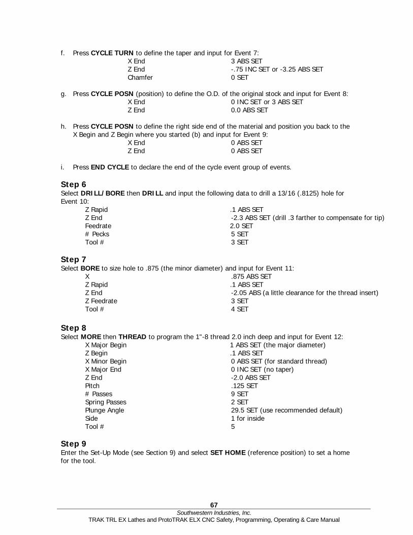
67 Southwestern Industries, Inc.
TRAK TRL EX Lathes and ProtoTRAK ELX CNC Safety, Programming, Operating & Care Manual
f. Press CYCLE TURN to define the taper and input for Event 7: X End 3 ABS SET Z End -.75 INC SET or -3.25 ABS SET Chamfer 0 SET
g. Press CYCLE POSN (position) to define the O.D. of the original stock and input for Event 8:
X End 0 INC SET or 3 ABS SET Z End 0.0 ABS SET
h. Press CYCLE POSN to define the right side end of the material and position you back to the
X Begin and Z Begin where you started (b) and input for Event 9: X End 0 ABS SET Z End 0 ABS SET
i. Press END CYCLE to declare the end of the cycle event group of events. Step 6 Select DRILL/BORE then DRILL and input the following data to drill a 13/16 (.8125) hole for Event 10: Z Rapid .1 ABS SET Z End -2.3 ABS SET (drill .3 farther to compensate for tip) Feedrate 2.0 SET # Pecks 5 SET Tool # 3 SET Step 7 Select BORE to size hole to .875 (the minor diameter) and input for Event 11: X .875 ABS SET Z Rapid .1 ABS SET Z End -2.05 ABS (a little clearance for the thread insert) Z Feedrate 3 SET Tool # 4 SET Step 8 Select MORE then THREAD to program the 1"-8 thread 2.0 inch deep and input for Event 12: X Major Begin 1 ABS SET (the major diameter) Z Begin .1 ABS SET X Minor Begin 0 ABS SET (for standard thread) X Major End 0 INC SET (no taper) Z End -2.0 ABS SET Pitch .125 SET # Passes 9 SET Spring Passes 2 SET Plunge Angle 29.5 SET (use recommended default) Side 1 for inside Tool # 5 Step 9 Enter the Set-Up Mode (see Section 9) and select SET HOME (reference position) to set a home for the tool.

68 Southwestern Industries, Inc.
TRAK TRL EX Lathes and ProtoTRAK ELX CNC Safety, Programming, Operating & Care Manual
For X Home, press 4, ABS SET and for Z HOME, 6, ABS SET to identify a point well off the part where the tool will go at Run start, tool change, and Run End. Press RETURN, MODE, DRO. Step 10 Load the part into the chuck. In the DRO Mode and with a facing tool, take a skim cut on the face of the part so that you have a consistent and flat surface to touch-off your tools. Use a micrometer or vernier to measure the part diameter and length. Press MODE, SET-UP, TOOL SET-UP. Step 11 Configure Tool #1 (the roughing turn/face tool). a. Mount the tool into its holder and mount on the tool post. b. Press 1, SET. c. Press SET NEW. d. Press 1, SET because Tool #1 is a right-hand turn/face tool. e. Using the handwheels, move the tool so that it touches the side of the part as shown by the
SET X line on the ProtoTRAK screen diagram. f. Input the part diameter (say 3.004), ABS SET. g. Move the tool so that it touches the face of the part as shown by the SET Z line on the
screen. h. Input a little bit over 0 (say 0.025), ABS SET so the first move will face off .025” i. Input the tool tip radius and SET. If you are using inserts, this radius will be shown on the
box. j. Ignore X MODIFIER and Z MODIFIER for now. k. Press BACK or SET, moving the highlight through the X and Z mod. Step 12 Configure Tool #2 (the finish turn/face tool). a. Mount the tool as in Step 11. b. Press 2, SET. c. Press SET NEW. d. Press 1, SET because Tool #1 is a right-hand turn/face tool.

69 Southwestern Industries, Inc.
TRAK TRL EX Lathes and ProtoTRAK ELX CNC Safety, Programming, Operating & Care Manual
e.-k. Follow the directions in Step 11 being sure in (h) to touch off the same place and input the same dimension as you used before. Step 13 Configure Tool #3 (the 13/16 drill). a. Follow the same pattern as above, inputting Tool #3 and selecting Drill (5). b. For setting X, touch the side of the drill to the side of the part nearest you and input the
3.004 part diameter. For setting Z, touch the tip to the end of the part and set the same number you did for Steps 11 or 12.
c. Input and SET the drill diameter when prompted. d. Press RETURN. Step 14 a. Configure Tool #4 (the boring bar). b. Follow the same pattern as above, inputting Tool #4 and selecting Bore (3). c. For setting X, touch the tool as shown to the side of the part away from you and input -3.004, ABS SET. Set Z and the Radius as above. d. Press RETURN. Step 15 Configure Tool #5 (the threading tool). a. Follow the same pattern as above, inputting Tool #5 and selecting Thread ID (8). b. For setting X, touch the tool as shown to the side of the part away from you (just as you did
with the boring tool) and input -3.004, ABS SET. Set Z as above. c. Press RETURN.

70 Southwestern Industries, Inc.
TRAK TRL EX Lathes and ProtoTRAK ELX CNC Safety, Programming, Operating & Care Manual
Step 16 While still in the Set-Up Mode, check your program by selecting TOOL PATH and pressing START. It should look like this:
Step 17 Run the part. a. Press MODE and select DRO. b. Load Tool #1 and press TOOL #, 1, SET. c. In the Z direction, touch Tool #1 to the end of the part and set Z = .025 ABS SET. d. Load a part and measure its diameter. e. Touch Tool #1 to the side of the part and set X = 3.004 ABS SET (or the diameter you
measured in [d] above). f. Press MODE, and select RUN. g. Press START then GO. The carriage will rapid so that Tool #1 is at home (X=4, Z=6). h. Start the spindle at an appropriate RPM. Note all feeds in the program assume a steel part.
Adjust if necessary. i. Press GO.

71 Southwestern Industries, Inc.
TRAK TRL EX Lathes and ProtoTRAK ELX CNC Safety, Programming, Operating & Care Manual
Step 18 Correcting the program to get a more accurate part. It is difficult in Tool Set-Up, Steps 11-15, to touch off the part with necessary precision. As a consequence, your part dimensions may not be exactly to print. To correct, or "tweak" a program: a. Run and then measure the first part. b. Enter Set-Up Mode and Select TOOL SET-UP. c. Enter the tool number that created the inaccurate cut. Select EDIT. d. Press DATA FWD to X Modifier or Z Modifier. Input the dimension equal to the part error.
Remember a plus X Modifier makes the diameter bigger, and a plus Z Modifier makes the part longer.
e. Re-run the part. f. If you can't risk ruining the first part, input a plus (for O.D.), or minus (for I.D.) .02 XMOD
and ZMOD for every tool. Then run the part, measure your errors, adjust the XMOD and ZMOD, and re-run.

72 Southwestern Industries, Inc.
TRAK TRL EX Lathes and ProtoTRAK ELX CNC Safety, Programming, Operating & Care Manual

Southwestern Industries, Inc
TRAK Warranty Policy
Warranty TRAK products are warranted to the original purchaser to be free from defects in work-manship and materials for the following periods:
Warranty Period Product Materials Factory Labor
New TRAK 1 Year 1 Year Any EXCHANGE Unit 90 Days 90 Days
The warranty period starts on the date of the invoice to the original purchaser from Southwestern Industries, Inc. (SWI) or their authorized distributor. If a unit under warranty fails, it will be repaired or exchanged at our option for a properly functioning unit in similar or better condition. Such repairs or exchanges will be made FOB Factory/Los Angeles or the location of our nearest factory representative or authorized distributor. Disclaimers of Warranties
• This warranty is expressly in lieu of any other warranties, express or implied, including any implied warranty of merchantability or fitness for a particular purpose, and of any other obligations or liability on the part of SWI (or any producing entity, if different).
• Warranty repairs/exchanges do not cover incidental costs such as installation, labor,
freight, etc.
• SWI is not responsible for consequential damages from use or misuse of any of its products.
• TRAK products are precision mechanical/electromechanical measurement systems and
must be given the reasonable care that these types of instruments require:
• Replacement of chip scrapers and wipers is the responsibility of the customer. Consequently, the warranty does not apply if chips have been allowed to enter the mechanism.
• Accidental damage, beyond the control of SWI, is not covered by the warranty. Thus,
the warranty does not apply if an instrument has been abused, dropped, hit, disassembled or opened.
• Improper installation by or at the direction of the customer in such a way that the
product consequently fails, is considered to be beyond the control of the manufacturer and outside the scope of the warranty.