Embed Size (px)
Citation preview

IMPLEMENTATION OF AUTOMATIC WEATHER OBSERVING SYSTEMS (AWOS) IN TURKEY
by Ercan BÜYÜKBAŞTurkish State Meteorological Service
Electronic Observing Systems DivisionKütükcü Alibey Cad. No:4 06120 Kalaba-Ankara-TURKEY
Tel:+90-312-302 27 80Fax:+90-312-361 23 53
e-mail: [email protected]
ABSTRACT
Turkey is very big country with different topographic and climate conditions. To be able to observe
the weather and to give the best meteorological service to the users, Turkish State Meteorological
Service (TSMS) has to operate a huge observing network of almost 500 stations of several types
and purposes. As a result of the modernization program of observing network under the execution
since 1997, most of those stations have been replaced with the automatic weather observing systems
(AWOS). We have been operating automatic weather observing systems in warmer conditions in
the southern part of the country while operating the same systems in very cold, snowy and severe
conditions in the eastern part of the country. On the other hand we have heavy rain in the northern
part of the country, and severe storm in the western part of the country. During the implementation
of the projects and operation of the systems, it has been clearly observed that the specifications of
the automatic weather observing systems should be determined very carefully by considering the
climate conditions to be exposed as well as the type of the data required from those systems.
This paper intends to give some information about the implementation of automatic weather
observing systems in Turkey and some special observing applications for harsh environment
conditions.
1. INTRODUCTION
The first and essential phase of preparation of the meteorological services and products is making
observations to watch and to understand the atmosphere. To be able to meet the increasing
meteorological requirements of the users in several sectors, reliable, accurate, continuous and
timely weather observations are needed which will be the essential input of weather forecasts and
numerical weather prediction models, research studies on climate and climate change, sustainable
1

development, environment protection, renewable energy sources, etc. All outputs and products of
any system are input dependant. So, accuracy, reliability and efficiency of the products of any
meteorological study will depend on its input: Observation.
By considering the importance of the observations for an efficient meteorological service for the
public as well as all domestic and international users, Turkish State Meteorological Service
(TSMS) started in 1997 the modernisation studies of meteorological systems, prepared
investments projects of great importance and got down to execution of them at a very high speed
with a view to rendering the best service to all users who demand meteorological support, and
furnish the users with more reliable data continually and to put to the service of the domestic and
international users the products and innovations developed by modern technology in the field of
meteorology.
One of the main components of those modernisation studies is the renovation of the existing
surface observation network and establishment of automatic weather observing systems as well as
other observing systems such as weather radars, upper air observing systems, meteorological
satellites, marine observing systems, etc.
2. SURFACE OBSERVATION NETWORK IN TURKEY
Turkey has a very difficult topography with high mountains, plateaus and river valleys for making
the observations and preparing the meteorological services, particularly weather forecasts (Figure
2.1). There are high mountains rising suddenly from the costal area in the southern and northern
part of the country and then plateaus and valleys appear. The inner and eastern part of the country
comprise with high mountains and plateaus, as well. On the other hand, there are also high
mountains with the plateaus and river valleys extending to perpendicular the coastal area in the
western part of the country.
2

Figure 2.1. Topographical Map of Turkey
So, TSMS has been operating a huge surface observation network spread all over the country
(Figure 2.2.) consisting of:
-Climatologic stations – 382 (161 automated)
-Synoptic stations – 125 (45 automated)
-Airport stations – 60 (36 automated)
Figure 2.2. Observation Network of TSMS
3

TSMS has been planning to equip all observing stations with automatic weather observing systems.
As the next step of that modernisation program, total 174 AWOS stations (98-climatological, 52-
synoptic and 24-airport) will be installed in 2008 and 2009. On the other hand, it is also planned to
install additional 200 AWOS stations by 2010 to complete the modernization program of surface
observation network. Thus, TSMS will have a fully automated surface observation network as
follows:
-Climatologic stations – 431(all automated)
-Synoptic stations – 125 (all automated)
-Airport stations – 60 (all automated)
Figure 2.3. AWOS Network of TSMS (Existing + Planned)
After the completion of the automatic weather observing systems;
• Institutional capacity will be strengthened.
• A meteorological observing network covering whole country will be established to provide
accurate, reliable and continuous meteorological data.
• It will be possible to get meteorological data from the regions in which manual observations
can not be made due to harsh environment conditions.
• The performance of the equipment in different climate regions, particularly for severe
weather conditions, shall be tested and monitored.
• The sectors such as transportation, energy, environment, agriculture, forestry, industry,
health, justice, local authorities, visual and written press will have a better meteorological
service and support.
4

• The need of meteorological data and support for disaster management, environmental
protection, use of renewable energy sources, sustainable development, research activities
and climate change activities will be able to be met more efficiently.
3. GENERAL STRUCTURE OF THE AWOS NETWORK
The AWOS network operated comprises of the following main components:
a) Data collection unit (DCU-Data logger):
Different types of DCUs are used for data acquisition. The features of DCUs are determined by
considering the requirements for the observations to be made. Some of the features of the data
loggers currently used in TSMS’ network are as follows:
-Analog inputs: Individually configurable, 24 single-ended or 12 differential channels
-Pulse counters: 4
-Digital I/O ports :8
-Analog outputs: 2
-Serial interfaces: RS-232, RS-485 ports
-A/D Conversion: 15 bit, 16 bit
-Storage capacity: 2MB (expandable with flash memory cards)
-EMI, RFI and ESD protection
-Power supply options: Mains, solar panel, rechargeable battery
-Environmental conditions: -40 °C to +60 °C temperature; 0-100% relative humidity;
The data measured and calculated are archived in data logger as 1-minute, 10-minute and daily
records. The data and archiving interval are configurable by the user.
The data loggers and sensors are mainly powered by mains power. This system also includes
rechargeable batteries and uninterruptible power supplies. On the other hand, in some cases where
the mains not available, solar panels are also used to feed the system. A proper lightning protection
and grounding system is also available in the station.
b) Sensors and sensor interfaces:
Sensors are chosen based on type of the stations. The parameters measured at the AWOS network
are given below:
5

PARAMETER SENSOR RANGE UNCERTAINITYWind Speed -Cup anemometer with
heater (pulse output or optical encoder), -Ultrasonic wind sensor
0 – 60 m / s ± 0.5 m/sec, up to 10 m/sec, ± 5 %, above 10 m/sec
Wind Direction - Wind wane (potentiometer or optical encoder), -Ultrasonic wind sensor
0 – 360 °C ± 3°
Temperature Platinum RTD (PT100) sensor;
-40°C….60 °C ± 0.2 °C
Humidity Thin-film polymer capacitive sensor
0-100 % 1%
Atmospheric Pressure Resonant or capacitive silicon pressure transducer
700 mb - 1100 mb ± 0.02%(± 0.22 hPa)
Open Screen Temperature (at 1 and 2 meter)
Platinum RTD (PT100) sensor
0-100 ± 0.2 °C
Open Screen Relative Humidity (at 1 and 2 meter)
Thin-film polymer capacitive sensor
0-100 % 1%
Precipitation -Tipping bucket rain gauge with heater, -Disdrometer
0-10 mm / min 1 tip(0.2 mm) or ±1%
Terrestrial Temperature
Platinum RTD (PT100) sensor
40°C….75 °C ± 0.2 °C
Temperature of Soil Depth (5, 10, 20, 50 and 200 cm)
Platinum RTD (PT100) sensor
-40°C…75 °C ± 0.2 °C
Soil Moisture Water content reflectometer
%0 …. %100 ± 4%
Snow Depth Ultrasonic Depth Sensor 0- 500 cm ±1 cm or 0.4% distance to target(at 5 meter range ±2 cm)
Direct Solar Radiation Pyrheliometer 0-1500 W/m² ±1.5 % (in daily total)
Global Solar Radiation Pyranometer 0-1500 W/m² ±2.6 % (in daily total)
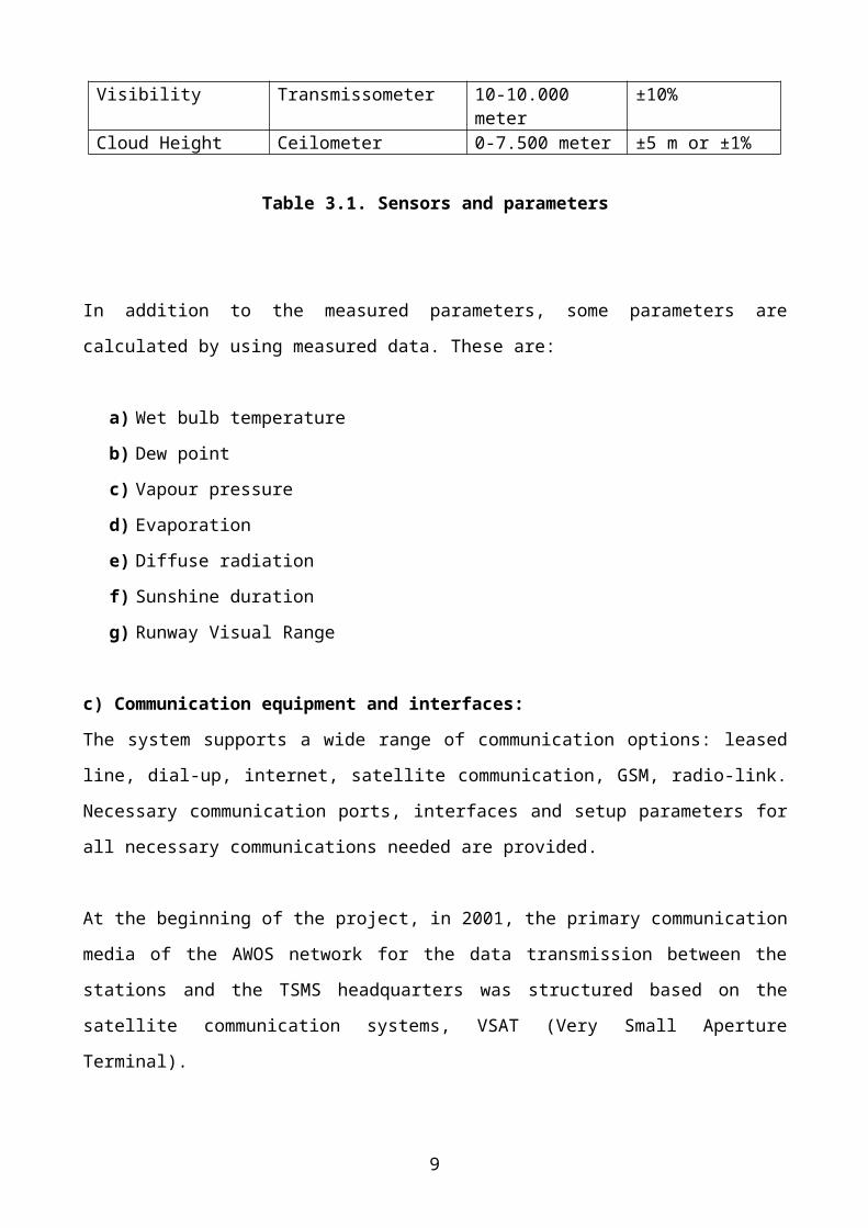
Visibility Transmissometer 10-10.000 meter ±10%Cloud Height Ceilometer 0-7.500 meter ±5 m or ±1%
Table 3.1. Sensors and parameters
In addition to the measured parameters, some parameters are calculated by using measured data.
6

These are:
a) Wet bulb temperature
b) Dew point
c) Vapour pressure
d) Evaporation
e) Diffuse radiation
f) Sunshine duration
g) Runway Visual Range
c) Communication equipment and interfaces:
The system supports a wide range of communication options: leased line, dial-up, internet, satellite
communication, GSM, radio-link. Necessary communication ports, interfaces and setup parameters
for all necessary communications needed are provided.
At the beginning of the project, in 2001, the primary communication media of the AWOS network
for the data transmission between the stations and the TSMS headquarters was structured based on
the satellite communication systems, VSAT (Very Small Aperture Terminal).
Figure 3.1. Communication Infrastructure via VSAT and PSTN
In case of any interruption in the satellite communication line, a back-up communication line was
7

designed as terrestrial communication line via PSTN network.
The fast development on the communication technologies offered new options for the data
transmission. In 2005, communication infrastructure and data transmission methods of the network
have been upgraded to use the GSM network via GPRS for the data transmission. During that
upgrading process, the data visualisation and archiving tasks have been also upgraded by
considering the new requirements of TSMS and the other users.
Figure 3.2. Current Communication Infrastructure
d) Data processing and data presentation software:
TSMS developed a very efficient and flexible data processing and data presentation software
running on the data collecting and archiving server. This software runs on the central server. The
server collects all data from the stations, applies quality control algorithms, generates the reports,
distribute to the required terminals and users and monitor the data. The data and reports are archived
in the database server. Any data of any station for any time can be retrieved and monitored. The
8
data collection and archiving intervals are configurable as 1- minute, 5- minute, 10-minute, 30-
minute, 60-minute (hourly) or 1440-minute (daily). All visualisation process
The following figures show the examples of the visualisation of the collected data in the central
server:
Figure.3.3. Main Page of WEB Interface for Data Visualisation
9

Figure.3.4. Example of the WEB Page to Select the Stations on the Map for the Visualisation
Figure.3.5. Example of the Visualisation of Instantaneous Data for a Station
10

Automatic Weather Station Data Presentation / 30 August 2008 14:00 GMT /
Station Last Hour Temperature Today Precipitation Today Temperature
Yesterday Precipitation Yesterday
Name Height Temp. Pressure Prep. Min Max Total 00-06
06-12
12-18
18-00 Min Max Total 00-
0606-12
12-18
18-00
Acisu Tepesi Radar 1112 --- --- 0 15,4 22,9 0 0 0 0 --- 15,9 27 0 0 0 0 0
Bartin 33 27,2 1006,7 0 18,7 29 0 0 0 0 --- 16 30,2 0 0 0 0 0Zonguldak Bölge 135 25,2 995,3 0 20,2 26,1 0 0 0 0 --- 18,6 25,9 0 0 0 0 0Çatalca Radar 381 --- --- 0 19,3 28,5 0 0 0 0 --- 19,5 25,1 0 0 0 0 0Istanbul Bölge (Krt) 18 27,4 1007,8 0 20,5 27,9 0 0 0 0 --- 22,2 30,3 0 0 0 0 0
Samandira 123 29 995,4 0 17,7 30 0 0 0 0 --- 20 29,2 0 0 0 0 0Kocaeli 76 30,5 1001 0 20 31,5 0 0 0 0 --- 21,7 31,8 0 0 0 0 0Gölcük 18 28 1007,6 0 20 28,3 0 0 0 0 --- 21,8 33,5 0 0 0 0 0Sakarya 30 31,4 1006,2 0 20,4 33,3 0 0 0 0 --- 21 31,2 0 0 0 0 0……….………….Ceylanpinar Tigem 360 38,5 962,2 0 23,3 38,7 0 0 0 0 --- 26,5 42,8 0 0 0 0 0
Kale-Demre 25 34,5 1004,9 0 24,6 35,4 0 0 0 0 --- 26,2 33,9 0 0 0 0 0
Figure.3.6. Example of the Visualisation of Data from All Stations in the Network
e) Basic features of AWOS network
The AWOS network operated by TSMS is capable of:
a) Collecting, processing and displaying meteorological data,
b) Performing automated generation and transmission of meteorological reports,
c) Being configured to support a wide range of sensor configurations,
d) Supporting a vast range of data communication options,
e) Managing all communication protocols for the various sensors and other data
communication equipment,
f) Storing all relevant data for subsequent retrieval as required,
g) Allowing for manual input of additional information unable to be automatically measured,
h) Providing Quality Control on both data measurements and message generation,
i) Allowing authorised users to access remotely for any tasks to be performed,
j) Configurable and automatically switchable for different operation modes,
k) Supporting message transmission for any time intervals,
4. MEASUREMENTS IN DIFFERENT CLIMATE CONDITIONS
11

Although most of the AWOS stations of TSMS have been installed in urban areas, they are exposed to
different climate conditions. They are operated in very hot and humid regions in southern and western
part of Turkey while operated in very cold and relatively dry regions in central and eastern part of
Turkey. AWOS are exposed to heavy rain in northern part, and strong storms in western part as well.
Responses, performances and mean time between failures (MTBF) of the systems are affected very
much from those conditions. Some cases encountered are summarized below with pictures:
a) Cup anemometers and wind wanes are damaged more frequently in the stations in stormy
areas than those in the other regions. This is why sensors and wind mast should be chosen
strong enough and must be installed properly by considering the wind conditions in the area
for the installation.
b) Another problem for the wind sensors is the freezing in the cold regions. In such cases heated
type sensors should be chosen by considering the power requirements for the heating.
Ultrasonic wind sensors may also be a proper solution for the problems regarding the cup
anemometers and wind wanes.
c) Uncertainty of tipping bucket rain gauges increases dramatically in the cold regions due to the
freezing even they have heater. A well designed heating system for both funnel and bucket
12

may minimize the problem. Other measuring techniques such as weighing type and optical
ones should also be considered for such conditions.
d) In some cases in the areas in which heavy rain occurs for the areas such conditions,
measurements are much less than the real one due to some loss of the precipitation during
measurement. Discharge capacity and measuring resolution for the rain gauges in such areas
should be selected by considering the rainfall accumulation per time to get accurate
measurements.
e) All equipment may be exposed to corrosion in the humid and salty areas. This highly affects
the performance of the equipment as well as their life cycle. Such conditions may also cause
frequent faults in the equipment and deficiencies in the measurements. Housing and
environmental protection class should be selected properly to protect the system, and
necessary isolations should be applied on the connection points and entrance of the cables.
13

f) Another problem is the dust, insects, salt and humidity for the temperature and humidity
sensors and radiation shields. They contaminate the filter of the sensing part of the sensor
probe and affect the measurement accuracy. They also fill the gaps of the radiation shield
needed for the natural ventilation for an accurate measurement. A frequent preventive
maintenance and cleaning is needed in such cases.
g) Dust, insects, salt and humid may also cause problems for some type of pressure sensors by
blocking the air pipe open to the atmosphere. A frequent preventive maintenance and cleaning
is needed in such cases, too.
h) The use of radiation shields for the temperature and humidity sensors in snowy areas may also
be problem. The gaps of radiation shield are filled with snow and ice and measurement are
affected very much. To install the radiation shield and sensor in an extra radiation shield of
wooden with larger gaps may minimize the effects of he snow and ice.
i) Heavy rain and snow may cause problems, e.g. corrosion and short circuit in the boards, in the
system. This is why these conditions should be considered and the power distribution box and
data logger housing should be installed at a proper height in such areas.
j) Hail is another severe weather phenomena causing damages in the systems. For such areas,
robust equipment should be selected.
14

k) Lightning is always a potential risk for the systems. A well designed and efficient lightning
protection and grounding system including surge protectors should be installed for the
mitigation of lightning hazards.
15

l) It is observed that cables, cable pipes cable connections are damaged due to high temperature
and humid in some areas. Inner design of the power box and data logger housing should be
made properly to minimize the negative effects of high temperature and humid. To use the
high quality material is also important.
m) In cold areas, snow and freezing affect the performance of the solar radiation sensors. The
heated type sensors can be used in the systems exposed to the snow and freezing.
n) Optical sensors are affected very much from dust. It should be preferred to choose instruments
with blowers.
o) Evaporation from lakes, rivers, plants and grass near the sensors may cause some incorrect
measurements of visibility sensors. This is why installation site should be chosen by
considering the site environment.
5. CONCLUSION
The automatic weather observing systems for the observations and measurements in different climate
regions even in harsh environment conditions can be used efficiently. Although some problems may
occur due to those conditions, proper solutions can be applied for increasing the performance of the
systems to get accurate data as required.
16

17

By considering the rapid increase in the use of automatic weather observing systems, it may be very
useful for the users of the systems to define the technical requirements and operation instructions
according to the different climate conditions.
18

.
19