Embed Size (px)
Citation preview
Trailer EBS C / DSystem Description
2nd Edition
This publication is not subject to change procedures.
New versions can be found in INFORM under
www.wabco-auto.com
© Copyright WABCO 2016
Vehicle Control Systems
Changes are subject to change without notice
Version 003/12.16815 010 020 3

2
Table of contents
1 Safety instructions. . . . . . . . . . . . . . . . . . . . . . . . . 3
2 System . . . . . . . . . . . . . . . . . . . . . . . . . . . . . . . . . . 4
2.1 Scope of application. . . . . . . . . . . . . . . . . . . . 4
2.2 System structure . . . . . . . . . . . . . . . . . . . . . . 5
2.3 Trailer EBS C . . . . . . . . . . . . . . . . . . . . . . . . . 6
2.4 Trailer EBS D . . . . . . . . . . . . . . . . . . . . . . . . . 7
2.5 Configuration . . . . . . . . . . . . . . . . . . . . . . . . . 8
3 Components . . . . . . . . . . . . . . . . . . . . . . . . . . . . . 13
3.1 Trailer EBS Modulator 480 102 0 . . 0 . . . . . 13
3.2 Park-release emergency valve (PREV)
971 002 900 0 . . . . . . . . . . . . . . . . . . . . . . . 15
3.3 Trailer emergency valve 971 002 301 0. . . . 15
3.4 EBS relay valve 480 207 001 0 . . . . . . . . . . 15
3.5 ABS Relay Valve 472 195 03. 0. . . . . . . . . . 16
3.6 Lifting axle valve 463 084 010 0
(dual circuit) . . . . . . . . . . . . . . . . . . . . . . . . . 16
3.7 Lifting axle valve 463 084 031 0
(single circuit). . . . . . . . . . . . . . . . . . . . . . . . 16
3.8 Double cut-off valve 434 500 003 0
(Select Low valve) . . . . . . . . . . . . . . . . . . . . 16
3.9 ECAS 446 055 066 0 . . . . . . . . . . . . . . . . . . 17
3.10 ELM 474 100 001 0 . . . . . . . . . . . . . . . . . . . 17
3.11 TCE 446 122 001 0 . . . . . . . . . . . . . . . . . . . 17
3.12 Pressure sensor 441 044 101 0 / 102 0. . . . 17
3.13 ABS sensor 441 032 808 0 / … 809 0 . . . . . 18
3.14 SmartBoard 446 192 110 0 . . . . . . . . . . . . . 18
3.15 Cable overview . . . . . . . . . . . . . . . . . . . . . . 19
3.16 Other components . . . . . . . . . . . . . . . . . . . . 23
4 Functional description. . . . . . . . . . . . . . . . . . . . . 24
4.1 Electro-pneumatic function . . . . . . . . . . . . . 24
4.2 Electrical / electronic system structure. . . . . 25
4.3 Warning signal sequences. . . . . . . . . . . . . . 27
4.4 Setpoint selection and pressure control. . . . 27
4.5 Load sensing brake control (LSV) . . . . . . . . 28
4.6 Pressure control. . . . . . . . . . . . . . . . . . . . . . 30
4.7 Anti-lock braking system (ABS) . . . . . . . . . . 30
4.8 Roll Stability Support (RSS). . . . . . . . . . . . . 31
4.9 Standstill function. . . . . . . . . . . . . . . . . . . . . 32
4.10 Emergency braking function . . . . . . . . . . . . 32
4.11 Test mode . . . . . . . . . . . . . . . . . . . . . . . . . . 32
4.12 Supply pressure monitoring . . . . . . . . . . . . . 33
4.13 Preventing automatic brake action at line tear-
off. . . . . . . . . . . . . . . . . . . . . . . . . . . . . . . . . 33
4.14 Odometer. . . . . . . . . . . . . . . . . . . . . . . . . . . 34
4.15 Service signal . . . . . . . . . . . . . . . . . . . . . . . 34
4.16 Integrated Lifting axle control ILS (Integrated
Load Switch) . . . . . . . . . . . . . . . . . . . . . . . . 34
4.17 Integrated Speed Switch ISS. . . . . . . . . . . . 36
4.18 Voltage output for vehicle level
control systems . . . . . . . . . . . . . . . . . . . . . . 37
4.19 Wear Indicator . . . . . . . . . . . . . . . . . . . . . . . 37
4.20 Additional functions of Trailer EBS D . . . . . 38
5 Diagnostics . . . . . . . . . . . . . . . . . . . . . . . . . . . . . 40
5.1 Setting the system parameters . . . . . . . . . . 40
5.2 Startup of a trailer . . . . . . . . . . . . . . . . . . . . 40
5.3 Troubleshooting. . . . . . . . . . . . . . . . . . . . . . 40
5.4 System diagnosis Trailer EBS . . . . . . . . . . . 41
6 Modulator exchange and Installation . . . . . . . . 47
6.1 Modulator exchange Trailer EBS C . . . . . . . 47
6.2 Electrical connections of the Trailer EBS
Modulator. . . . . . . . . . . . . . . . . . . . . . . . . . . 48
6.3 Pneumatic ports. . . . . . . . . . . . . . . . . . . . . . 51
6.4 Pneumatic lines and screw fittings . . . . . . . 51
6.5 System start-up . . . . . . . . . . . . . . . . . . . . . . 52
6.6 RSS installation regulation . . . . . . . . . . . . . 52
6.7 Installation regulation quick release valve
973 500 051 0 . . . . . . . . . . . . . . . . . . . . . . . 54
6.8 EBS system plate . . . . . . . . . . . . . . . . . . . . 55
6.9 Certificates. . . . . . . . . . . . . . . . . . . . . . . . . . 55
6.10 Trailer EBS test instruction -
a tool for experts . . . . . . . . . . . . . . . . . . . . . 56
7 Appendix 58
7.1 Functions / service for Trailer EBS / trailer
modulator 480 102 … 0 . . . . . . . . . . . . . . . . 58
7.2 CAN line test . . . . . . . . . . . . . . . . . . . . . . . . 59
7.3 Parameter settings for lifting axle control on a
semitrailer . . . . . . . . . . . . . . . . . . . . . . . . . . 60
7.4 Parameters load sensing. . . . . . . . . . . . . . . 61
7.5 Lifting Axle Circuit . . . . . . . . . . . . . . . . . . . . 63
7.6 Lifting axle dual circuit . . . . . . . . . . . . . . . . . 63
7.7 Braking system diagram Trailer EBS C . . . . 66
7.8 Braking system diagram Trailer EBS D . . . . 74

3
1Trailer EBSSafety instructions
1 Safety instructionsThis publication describes the system structure, functions and components of the
Trailer EBS generation C and D.
Read this document carefully. All instructions, notes, and safety instructions must be
adhered to in order to avoid personal injury and/or material loss.
WABCO will only guarantee the safety, reliability and performance of its products and
systems if all information provided in this document is observed.
• Only trained and qualified technicians are permitted to perform work on the vehi-
cle.
• Always follow specifications and instructions of vehicle manufacturer.
• Always comply with the company's regulations for the prevention of accidents and
national regulations.
• Wear any necessary protective clothing.
• Your workspace must be dry as well as sufficiently illuminated and ventilated.
Risk of injury! Pedal actions can cause serious injuries if persons are near the vehicle.
Ensure that pedal action is prevented by means of the following measures:
– Switch the gearbox to "neutral" and actuate the hand brake.
– Use brake wedges to secure the vehicle against rolling away.
– Attach a clearly marked note on the steering wheel saying that work is being per-
formed on the vehicle and that the pedal must not be applied.
– Do not wear a tie, bulky clothing, open hair, bracelets or watches, etc. when work-
ing on the vehicle, especially if the engine is running. Keep your hands and hair
away from moving parts.
Fire hazard! – Only use lamps with a ground connection.
– Keep flammable materials (cloth, paper, etc.) away from the exhaust system.
– Do not smoke at your workplace.
– Check the electrical lines to make sure they are properly insulated and fastened.

4
2 Trailer EBS System
2 SystemThe system Trailer EBS is an electronically controlled braking system with load-re-
lated braking pressure control and anti-lock braking system.
Trailers equipped with such braking systems may only be towed by:
• Motor vehicles with an extended ISO 7638-1996 plug-in connection (7-pin; 24
volts; towing vehicles with CAN data line)
• Motor vehicles with ISO 7638-1985 plug-in connection (5-pin, 24 volts; towing ve-
hicles with no CAN data line)
This must be documented by a corresponding entry in the vehicle title (in Germany
under under item 33).
2.1 Scope of application
Vehicles Trailer vehicles with one or more than one axle in classes O3 and O4 according to
the framework directive 70/156/EEC, Annex II with air suspension, disc or drum
brakes.
Trailer EBS D (with LSV valve): additional mechanical suspension.
Braking systems Power braking systems with a pneumatic transmission system as per the provisions
of the motor vehicle construction and use regulation or EC Guideline 71/320/EG or
ECE Directive No. 13.
Wheels and Tyres Single and twin tyres. For each axle whose rotational speed is sensed, identical tyre
dimensions and identical numbers of pole wheel teeth must be used.

5
2Trailer EBSSystem
2.2 System structure
2.2.1 History of the System
Integrated demand
pressure sensor with
TEBS D
Whilst with Trailer EBS C the demand pressure of the brake system and the air bel-
lows pressure were determined by external pressure sensors, Trailer EBS D modu-
lator has integrated pressure sensors.
For your information:
Trailer EBS E
A new Trailer EBS called generation E was introduced mid of 2007. The extended
functionality includes complete control of the air suspension in a central axle trailer
or semitrailer with lifting axle control. It can by operated using an ECAS remote con-
Version Dual release valveRelay Emergency
Valve
Demand
pressure
sensor
Trailer EBS ModulatorAxle load
sensor
Trailer
EBS C2
– 11/2001
with integrated demand pressure
sensor
Trailer
EBS C3
11/2001 –
09/2003
conventional + RSS
Trailer
EBS D
10/2003 –
conventional + RSS
Trailer
EBS D+
10/2003 –
Park-release emergency valve (PREV) + RSS
Trailer EBS C Trailer EBS D
Control pres-
sure
external pressure sensor for REV
at 1st port 4
integrated pressure sensor at
port 4
Bellows
pressure
external pressure sensor for air
bellow at 2nd port 4
integrated pressure sensor air
bellow at port 5
Diagram

6
2 Trailer EBS System
trol unit, an ECAS control box or the SmartBoard. Piping and wiring efforts of the trail-
er brake and air suspension system are reduced significantly.
Please find information and publication about Trailer EBS E in our product catologue
INFORM under www.wabco-auto.com in the Internet.
2.3 Trailer EBS C
Brake diagram T EBS C, 4S/2M for semitrailer
Trailer EBS C consists of an dual release valve, a relay emergency valve (1) with an
integrated demand pressure sensor (5) and brake switch (6), a trailer modulator (2)
with an integrated electronic control unit, integrated pressure sensors (5), integrated
redundancy valves (7) and an axle load sensor (4) plus the wiring for the compo-
nents.
This configuration is described as a 2S/2M or 4S/2M system, depending on the
number of speed sensors (3) used.
Supply
Control
7
2Trailer EBSSystem
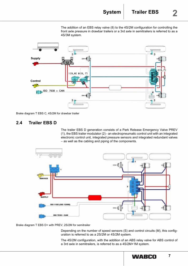
The addition of an EBS relay valve (8) to the 4S/2M configuration for controlling the
front axle pressure in drawbar trailers or a 3rd axle in semitrailers is referred to as a
4S/3M system.
Brake diagram T EBS C, 4S/2M for drawbar trailer
2.4 Trailer EBS D
The trailer EBS D generation consists of a Park Release Emergency Valve PREV
(1), the EBS trailer modulator (2) - an electropneumatic control unit with an integrated
electronic control unit, integrated pressure sensors and integrated redundant valves
– as well as the cabling and piping of the components.
Brake diagram T EBS D+ with PREV, 2S/2M for semitrailer
Depending on the number of speed sensors (S) and control circuits (M), this config-
uration is referred to as a 2S/2M or 4S/2M system.
The 4S/2M configuration, with the addition of an ABS relay valve for ABS control of
a 3rd axle in semitrailers, is referred to as a 4S/2M+1M system.
Supply
Control

8
2 Trailer EBS System
The addition of an EBS relay valve to the 4S/2M configuration for controlling the front
axle pressure in drawbar trailers or a 3rd axle in semitrailers is referred to as a 4S/3M
system.
2.5 Configuration
Trailer EBS supports the following ABS configurations:
• 2S/2M, 2 speed sensors and one trailer modulator for 1- to 3-wheel semitrailers
and central axle trailers with air suspension systems.
• 2S/2M + SLV, Extension to the configuration by a Select Low valve for controlling
a steering axleSteering axle on a semitrailer.
• 4S/2M, 4 speed sensors and one trailer modulator for 2- to 3-wheel semitrailers
and central axle trailers with air suspension systems.
• 4S/2M+1M, 4 speed sensors, one trailer modulator and one ABS relay valve for 2-
to 4-wheel semitrailers and 2- and 3-wheel central axle trailers with air suspension
systems.
• 4S/3M, 4 speed sensors, one trailer modulator and one EBS relay valve for 2- to 5-
axle drawbar trailers and 2- and 4-axle semitrailer or 2- to 3- axle central axle trail-
ers with air suspension systems.
2S/1M, 4S/4M and 6S/3M ABS configuration are not be supported.
Axles or wheels which have had no sensors fitted can be indirectly controlled by di-
rectly controlled axles or wheels.
Multi-axle assemblies require the utilisation of the adhesion to be roughly identical.
IF not all wheels are sensored the axle(s) that lock(s) in general at first has to be
equipped with a sensor.
Multi-axle assemblies with static axle load allocation only should be equipped in such
a way (brake cylinders, length of brake levers, etc.) that the wheels of all axles reach
the locking limit as simultaneously as possible and that a directly controlled wheel
does not indirectly control more than two wheels and on central axle trailer not more
than one wheel.
2.5.1 Installation recommendation for semitrailers, central axle trailers and drawbar
trailers
Lifting axles 2S/2M System: Lift axles are not to be sensed.
All other systems: Lift axles can be sensed with ABS sensors of axles e, f.
Steering axles Constrained steering axles can be treated like rigid axles. WABCO prescribes EBS
configurations 4S/3M, 4S/2M+1M or 2S/2M+SLV for vehicles with self-steering ax-
les.
If 2S/2M or 4S/2M EBS-systems are to be used in vehicles with self-steering axles,
tests during the type test must establish that there are no abnormal axle vibrations

9
2Trailer EBSSystem
or course deviations. It is not possible to investigate all axles on the market to check
how they respond when ABS is triggered.
Assignment of control channels (according to schemes 841 801 620 up to 841 801
622 0)
Notation Explanation
Driving direction
Trailer modulator
Two-Way Valve (SHV)
Double cut-off valve (SLV)
EBS Relay Valve
ABS relay valve
*
These types of vehicle are not listed in the "Type approval report for
ABS brake systems in trailers" no. 123.4 and require separate ac-
ceptance.
** up from Trailer EBS generation D
Modulator Sensors
sensed (directly controlled)
not sensed (indirectly controlled)
System axle Control electronics
M c, d Main axle (not lifting) IR/MSR
A/E e, f Steering axle (lifting) MAR
Z e, f Additional axle (lifting) MSR

10
2 Trailer EBS System
Central axle trailers and semitrailers
Vehicle type 2S/1M 2S/2M 4S/2M 4S/3M 4S/2M + 1M
2S/2M + SLV
2S/2M + SLV
2S/2M + SLV
+
+

11
2Trailer EBSSystem
Drawbar trailer
Semi trailer and drawbar trailer(separate acceptance required)
Vehicle type 2S/2M 4S/2M 4S/3M 4S/2M + 1M
**
Vehicle type 2S/2M 4S/2M 4S/3M 4S/2M + 1M
*
*
1

12
2 Trailer EBS System
Vehicle type 2S/2M 4S/2M 4S/3M 4S/2M + 1M
*
*
1

13
3Trailer EBSComponents
3 Components
3.1 Trailer EBS Modulator 480 102 0 . . 0
The trailer modulator is used for controlling and monitoring the elec-
tropneumatic brake system. It controls the brake cylinder pressure
on both sides of one, two or three axles.
The trailer modulator is installed in the electropneumatic braking
system between reservoir tank or EBS trailer emergency valve (with
T-EBS C) or Park release emergency valve (with T-EBS D) and
brake cylinder nearby the axles on the frame (e. g. on a 3-axle trailer
above the second axle).
The trailer modulator has two pneumatically independent pressure
control channels, each with an air admitting and an air exhausting
valve, a redundant valve, a pressure sensor and a shared control
ECU as well as an electrical connection for an ABS or EBS relay
valve. The brake cylinder pressures on an axle can be controlled separately using
this connection.
The wheel speeds are recorded and evaluated by up to four speed sensors. If the
wheels start to lock, the brake pressure specified for the brake cylinders is reduced
by the ABS control circuit.
The reservoir pressure is detected by an integrated pressure sensor. If the reservoir
pressure drops below 4.5 bar, the driver is warned by the red and yellow warning
lights.
If an expanded ISO 7638 plug device is used, the trailer modulator communicates
with the tractive unit via the electrical trailer interface according to ISO 11992 (1998-
04-01). A bidirectional data interface according to ISO 14230 (KWP 2000) is provided
for diagnosis of the trailer modulator.
3.1.1 Modulator Trailer EBS C
If a CAN interface is available, the vehicle’s nominal delay is determined of the CAN
braking signal of the towing vehicle. In other cases the nominal delay is based on the
received pressure signal of the EBS trailer emergency valve.
A connection for a axle load sensor can be found on the trailer modulator. The brake
force is adapted depending on the vehicle load (load-dependent brake force control).
Variants of the modulator Trailer EBS C(up to week 48/2001: T-EBS C2, from week 49/2001: T-EBS C3)
WABCO no. 480 102 000 0 480 102 001 0 480 102 002 0 480 102 004 0 480 102 005 0
ABS configuration max. 4S/3M max. 4S/3M max. 4S/3M max. 4S/3M max. 4S/3M
Battery charge X X
to be used with TCE X X
RSS X X
Connection wear indicator X X X
Switching output 1 / 2 X X X
1

14
3 Trailer EBS Components
3.1.2 Modulator Trailer EBS D
With Trailer EBS D, the setpoint deceleration of the vehicle is calculated with an in-
tegrated pressure sensor by measuring the pneumatic control pressure of the trac-
tive unit and – if a trailer interface is available – the CAN setpoint. In vehicles with
critical timing characteristics, it is possible to connect an additional separate brake
pressure sensor as an option in order to improve the timing response.
The trailer modulator has an integrated axle load sensor. In addition, a separate axle
load sensor can be connected, for example so that a pressure sensor with a larger
measuring range can be used with hydraulic suspension systems. The brake force
is modified depending on the vehicle load (load-dependent brake force control).
A second CAN interface (ISO 11992 or ISO 11898) can be used for connecting a
telematic system or a second trailer modulator.
Variants of the
modulator Trailer EBS D
480 102 010 0 - standard 4S/2M
Fits to semi trailers without TCE.
480 102 014 0 - Premium 4S/3M
Fits to drawbar or semi trailers without TCE.
The version has an electrical connection for an external EBS or ABS relay valve. The
brake cylinder pressures on an axle can be controlled separately when an EBS relay
valve is connected. When an ABS relay valve is connected, the specified brake pres-
sure can be controlled separately for an axle by the ABS control loop if a wheel is
starting to lock.
The RSS (roll stability support) function can be activated. When the RSS function is
activated, the trailer is braked automatically if the risk of overturning is detected.
When operating with ECAS/ELM, a battery can be connected for operating the trailer
independently without the tractive unit. The current for charging the battery is restrict-
ed by the EBS electronic control unit in order to prevent any overload of the connect-
ed cables. The battery is charged from the tractive unit's electrical system when the
power intake is higher than 24 V and no EBS/ABS brake operation is performend
480 102 015 0 - TCE + 4S/2M
Fits to drawbar or semi trailers only in combination with TCE (no separate installa-
tion).
Function480 102 010 0
Standard
480 102 014 0
Premium
480 102 015 0
with TCE
ABS system max. 4S/2M max. 4S/3M max. 4S/3M
CAN bus 24 V (ISO 7638 X X
CAN bus 5 V X
Brake light supply X X
Switching output 1 / 2 X X
Traction help X X
Wear sensing X X
2nd CAN bus (IVTM etc.) X
Battery charge for ECAS X
RSS X X
Connection external Brake pres-
sure sensorX X
Connection external Axle load
sensorX X X
1

15
3Trailer EBSComponents
3.2 Park-release emergency valve (PREV) 971 002 900 0
In the trailer EBS D generation, the typical functions of the trailer emergency valve
such as the line break function or pressure retention must be assured when the trailer
is unhitched. The park-release emergency valve should preferably be used for this
purpose. However, these functions can also be ensured by a conventional or an EBS
trailer emergency valve.
The park-release emergency valve provides the functions of emergency braking in
case of a pneumatic supply line break and the double release valve function.
The black actuation button (release button of the service brake system) enables the
brake system to be released manually following automatic braking when the vehicle
is parked up without any compressed air supply. However, there must be sufficient
reservoir pressure in the tank to permit this.
The red actuation button (actuation of the parking brake system) enables the parking
brake to be applied or released by venting the spring-type brake actuators.
When the trailer is unhitched (supply line evacuated), it is braked automatically by
the service brakes and, at the same time, the non-return valve integrated in the park-
release emergency valve is bypassed in the spring-type brake actuator circuit. If the
reservoir pressure in the parked trailer drops, the spring-type brake actuators auto-
matically take over providing the braking effort and prevent the vehicle from rolling
away.
All control functions are active in case of a supply line break.
3.3 Trailer emergency valve 971 002 301 0
Trailer EBS C
The conventional trailer emergency valve is used up from Trailer EBS C3 generation
in combination with an external demand pressure sensor.
Trailer EBS D
Trailer EBS D generation operates with a conventional trailer emergency valve with-
out external demand pressure sensor because it is integrated in the modulator.
It is important to use a trailer emergency valve without predominance.
3.4 EBS relay valve 480 207 001 0
The EBS relay valve is used in the Trailer EBS C as an actuator for modulating the
brake pressures in the front axle of drawbar trailers or a 3rd axle in semitrailers.
The EBS relay valve consists of a relay valve and two solenoid valves (air
admitting/air exhausting valve), a redundant valve and a pressure sensor. Electrical
control and monitoring is performed by the modulator Trailer EBS C.

16
3 Trailer EBS Components
3.5 ABS Relay Valve 472 195 03. 0
The ABS relay valve familiar from conventional brake systems and a double non-re-
turn valve are used in the electropneumatic brake system as an actuator for modu-
lating the brake pressures on a steering axle of semitrailers. Electrical control and
monitoring is performed by the trailer modulator.
3.6 Lifting axle valve 463 084 010 0 (dual circuit)
An electrical lifting axle valve can be used to control up to two lifting axles automati-
cally via the trailer EBS relative to the current axle load. Electrical control and moni-
toring is performed by the trailer modulator.
3.7 Lifting axle valve 463 084 031 0 (single circuit)
Using a single circuit lifting axle valve, a lifting axle can be automatically controlled
by the trailer EBS D depending on the current axle load. Electrical control and mon-
itoring is performed by the trailer modulator.
A traction help with residual pressure holding is possible after unscrewing the vent.
To do this, a line is routed from the vent to the 3/2-way solenoid valve for residual
pressure holding.
To do this, cable 449 764 … 0 must be connected to the IN/OUT1 connection of the
Trailer EBS D modulator. The lifting axle valve vent (connection 3) is shut off by a 2-
way valve, vented accordingly by the EBS D modulator and the maximum possible
bellows pressure is retained. The traction help can be activated by a button (see
chapter 4.16 „Integrated Lifting axle control ILS (Integrated Load Switch)“, page 34).
Lifting axle valve 463 084 031 0 replaces the previous version 463 084 030 0.
3.8 Double cut-off valve 434 500 003 0 (Select Low valve)
The double cut-off valve is used in vehicles with 2S/2M + Select Low control in order
to provide axle-by-axle braking (e.g. steering axle). The input pressures are the pres-
sures output by the trailer modulator for each side. The lower pressure is then direct-
ed to the axle to be braked.

17
3Trailer EBSComponents
3.9 ECAS 446 055 066 0
An electronic air suspension system ECAS can be connected in series with
the trailer EBS. Electrical control and monitoring is performed by the trailer
modulator. If ECAS is installed, a battery can be connected to the trailer
modulator (480 102 014 only) by means of which ECAS can be operated
without the trailer being hitched to a tractive unit.
Please find information and publication about ECAS in our product cato-
logue INFORM under www.wabco-auto.com in the Internet.
3.10 ELM 474 100 001 0
An electronic air suspension module ELM can be connected in series with
the trailer EBS. Electrical control and monitoring is performed by the trailer
modulator.
Please find information and publication about ELM in our product catologue
INFORM under www.wabco-auto.com in the Internet.
3.11 TCE 446 122 001 0
The trailer EBS can be expanded by a trailer central electronic unit (TCE).
Electrical power supply, sensor data transmission (except for speed
sensors and any external brake pressure sensor fitted) and monitoring of
the trailer EBS is performed by the TCE.
Please find information and publication about TCE in our product catologue
INFORM under www.wabco-auto.com in the Internet.
! If TCE is fitted, the following modulators can be used only
Trailer EBS C: 480 102 002 0, 480 102 005 0
Trailer EBS D: 480 102 015 0
Usage of different modulators will cause an error message by TCE During
startup, the trailer EBS is taken into service first, followed by the TCE.
3.12 Pressure sensor 441 044 101 0 / 102 0
The pressure sensors 441 044 101 0 / 102 0 replace the previous versions 441 040
013 0 / 015 0
Trailer EBS C
Traler EBS C is using an axle load sensor (pressure sensor) to measure the bellows
pressure of the air suspension system. Depending on the bellows pressure a brake
force control not depending on the load is carried out. Electrical control and
monitoring is performed by the trailer modulator.

18
3 Trailer EBS Components
The axle load sensor has to measure the bellows pressure of one axle which is not
lifted. At drawbar trailes, the axle load sensor must observe the bellows pressure of
the axle which is controlled by the modulator (and not the axle with the 3rd
modulator).
Air suspension systems with a levelling valve can be connected with the axle load
sensor on each air suspension bellow.
By air suspension systems with two levelling valves ( side wise control of the level)
the axle load sensor has to has more bellows pressure which he he gets by a two-
way valve.
Trailer EBS D
An external brake pressure sensor for improving timing characteristics can be con-
nected to the Trailer EBS D IN/OUT2 port (all versions except for 480 102 010 0).
This pressure sensor measures the control pressure in the brake line and transmits
the measured value to the trailer modulator.
Additionally, an external axle load sensor can be connected at IN/OUT1.
The pressure sensor may also be used during servicing if an internal demand pres-
sure sensor fails.
When the external pressure sensor is connected, the relevant internal one is not ac-
tive.
3.13 ABS sensor 441 032 808 0 / … 809 0
Type Splus sensors are used as ABS sensors. ABS sensors 441 032 808 0 (cable
length 400 mm) or … 809 0 (cable length 1,000 mm) are used.
Sensor sets 441 032 921 2 (cable lenght 400 mm) or … 922 2 (cable lenght 1,000
mm) are recommended as replacement solution.
3.14 SmartBoard 446 192 110 0
The SmartBoard is a display and control panel for trailer vehicles and combines the
following functions:
• Display of distance driven (operates without power supply from the towing vehicle)
• Brake lining wear indicator (in connection with WABCO BVA)
• Current axle load indicator
• Tyre pressure indicator (in connection with WABCO IVTM)
• Display of diagnostics and system messages
The SmartBoard functions in combination with every Trailer EBS D system with a
Premium ECU 480 102 014 0 of week of manufacture 51/03 or later according to the
type plate or 2003 CW51 according to the Diagnostic Software.
Assembly The SmartBoard is simply screwed onto the exterior of the frame and connected to
the Trailer EBS D modulator via cable. The distance between the Trailer EBS D ECU
and the desired point of installation determines the cable length:
• Cable 449 377 030 0: 3 m
19
3Trailer EBSComponents
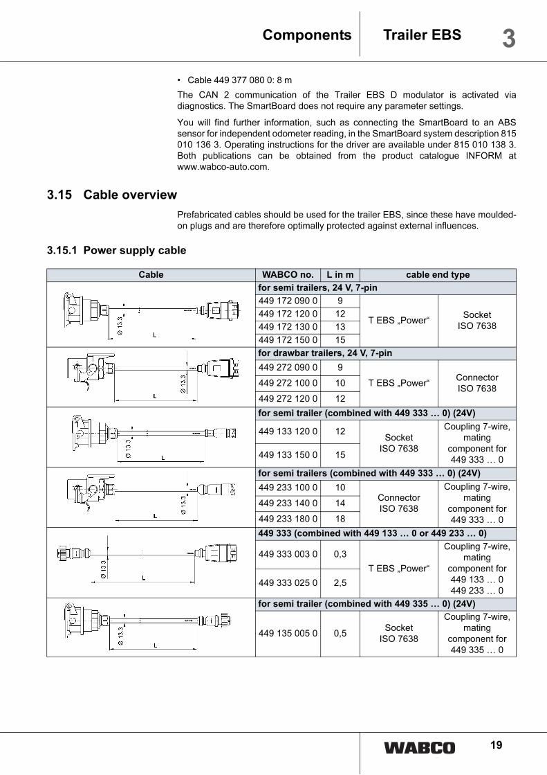
• Cable 449 377 080 0: 8 m
The CAN 2 communication of the Trailer EBS D modulator is activated via
diagnostics. The SmartBoard does not require any parameter settings.
You will find further information, such as connecting the SmartBoard to an ABS
sensor for independent odometer reading, in the SmartBoard system description 815
010 136 3. Operating instructions for the driver are available under 815 010 138 3.
Both publications can be obtained from the product catalogue INFORM at
www.wabco-auto.com.
3.15 Cable overview
Prefabricated cables should be used for the trailer EBS, since these have moulded-
on plugs and are therefore optimally protected against external influences.
3.15.1 Power supply cable
Cable WABCO no. L in m cable end type
for semi trailers, 24 V, 7-pin
449 172 090 0 9
T EBS „Power“Socket
ISO 7638
449 172 120 0 12
449 172 130 0 13
449 172 150 0 15
for drawbar trailers, 24 V, 7-pin
449 272 090 0 9
T EBS „Power“Connector
ISO 7638449 272 100 0 10
449 272 120 0 12
for semi trailer (combined with 449 333 … 0) (24V)
449 133 120 0 12Socket
ISO 7638
Coupling 7-wire,
mating
component for
449 333 … 0449 133 150 0 15
for semi trailers (combined with 449 333 … 0) (24V)
449 233 100 0 10Connector
ISO 7638
Coupling 7-wire,
mating
component for
449 333 … 0
449 233 140 0 14
449 233 180 0 18
449 333 (combined with 449 133 … 0 or 449 233 … 0)
449 333 003 0 0,3
T EBS „Power“
Coupling 7-wire,
mating
component for
449 133 … 0
449 233 … 0449 333 025 0 2,5
for semi trailer (combined with 449 335 … 0) (24V)
449 135 005 0 0,5Socket
ISO 7638
Coupling 7-wire,
mating
component for
449 335 … 0

20
3 Trailer EBS Components
3.15.2 Solenoid cable
3.15.3 Relay Emergency Valve
499 335 (combined withcombined with 449 135 … 0)
449 335 110 0 11
T EBS „Power“
Coupling 7-wire,
mating
component for
449 135 … 0449 335 140 0 14
open ends with EBS plug (24 V) 7-pin
449 373 090 0 9
T EBS „Power“ 7-pin open ends
449 373 120 0 12
Cable WABCO no. L in m cable end type
Relay valve (drawbar trailer, 3rd modulator)
449 372 030 0 3
T EBS
„Modulator“
Socket Kostal
1× M24×1
1× M27×1
1× DIN 72585
B1-3.1-Sn/K1
449 372 060 0 6
449 372 080 0 8
449 372 120 0 12
449 372 130 0 13
ABS relay valve (3rd modulator)
449 427 020 0 2T EBS
„Modulator“
Socket bajonet
DIN 72585 B1-
3.1-Sn/K1449 427 030 0 3
Cable WABCO no. L in m cable end type
Relay Emergency Valve 971 002 802 0
449 472 030 0 3
T EBS
„IN/OUT2“
Socket bajonet
DIN 72585 B2-
4.1-Sn/K1
449 472 035 0 3,5
449 472 050 0 5
449 472 080 0 8
449 472 120 0 12
449 472 130 0 13
449 472 145 0 14,5
Ext. pressure sensor and Relay Emergency Valve 971 002
301 0
449 473 010 0 1
T EBS
„IN/OUT2“
Socket bajonet
DIN 72585 B1-
4.1-Sn/K1
449 473 030 0 3
449 473 050 0 5
449 473 080 0 8
449 473 120 0 12
449 473 130 0 13
449 473 145 0 14,5
Cable WABCO no. L in m cable end type
Supplied package: is fitted by the customer
21
3Trailer EBSComponents
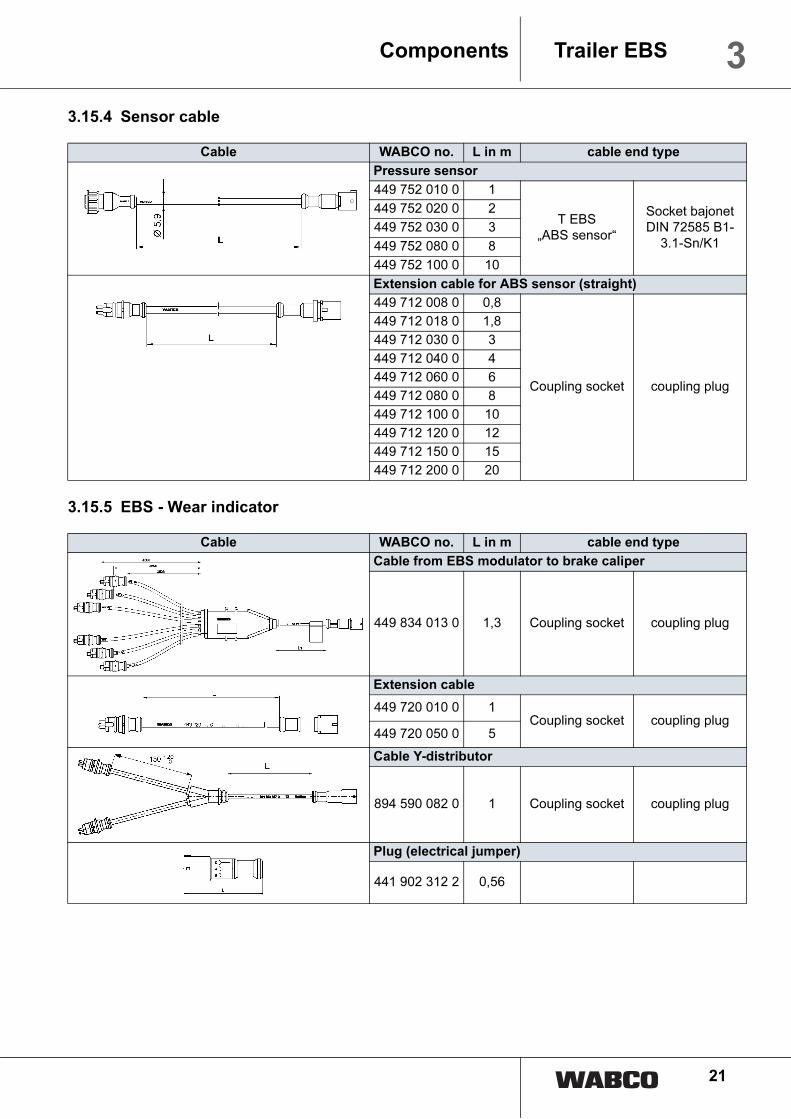
3.15.4 Sensor cable
3.15.5 EBS - Wear indicator
Cable WABCO no. L in m cable end type
Pressure sensor
449 752 010 0 1
T EBS
„ABS sensor“
Socket bajonet
DIN 72585 B1-
3.1-Sn/K1
449 752 020 0 2
449 752 030 0 3
449 752 080 0 8
449 752 100 0 10
Extension cable for ABS sensor (straight)
449 712 008 0 0,8
Coupling socket coupling plug
449 712 018 0 1,8
449 712 030 0 3
449 712 040 0 4
449 712 060 0 6
449 712 080 0 8
449 712 100 0 10
449 712 120 0 12
449 712 150 0 15
449 712 200 0 20
Cable WABCO no. L in m cable end type
Cable from EBS modulator to brake caliper
449 834 013 0 1,3 Coupling socket coupling plug
Extension cable
449 720 010 0 1Coupling socket coupling plug
449 720 050 0 5
Cable Y-distributor
894 590 082 0 1 Coupling socket coupling plug
Plug (electrical jumper)
441 902 312 2 0,56

22
3 Trailer EBS Components
3.15.6 Diagnostic cable
Cable WABCO no. L in m cable end type
Diagnosis and ISS or ILS
449 614 148 0 3 / 3
T EBS
„Diagnosis“
Diagnostic
socket; 3-pin, 3×
0,75 mm²
449 614 153 0 6 / 3
449 614 253 0 6 / 6
449 614 295 0 8 / 8
Diagnosis and ILS
449 624 113 0 6 / 2T EBS
„Diagnosis“
Socket
Diagnosis; socket
M 27×1
Diagnosis and ILS1/ILS2 stop light supply
449 684 153 0 6 / 3
T EBS
„Diagnosis“
Socket
Diagnosis, 4-pin,
2× 0.5 mm²,
2× 2.5 mm²
449 684 313 0 6 / 10
449 684 333 0 6 / 12
Diagnosis and ECAS
449 382 010 0 1
T EBS
„Diagnosis“
PG 11, 7-pin
3× 1.5 mm²
4× 0.5 mm²
6 with cable
shells
449 382 015 0 1,5
449 382 060 0 6
449 382 080 0 8
449 382 090 0 9
Diagnosis and single-circuit lifting axle valve
449 664 050 0 4 / 1
T EBS
„Diagnosis“
Socket
Diagnosis; socket
bajonet DIN
72585 B1-3.1-
Sn/K1
449 664 190 0 4 / 4
449 664 253 0 6 / 6
Diagnosis and ELM
449 344 246 0 6 / 2
T EBS
„Diagnosis“
Socket
Diagnosis; elbow
bajonet DIN
15170 B1-3.1-
Sn/K1449 344 253 0 6 / 6

23
3Trailer EBSComponents
3.15.7 Cable for traction help button
3.15.8 Sealing plug for Trailer EBS modulator
3.16 Other components
Diagnostics
449 672 030 0 3
T EBS
„Diagnosis“Socket Diagnosis
449 672 040 0 4
449 672 050 0 5
449 672 060 0 6
449 672 080 0 8
Cable WABCO no. L in m cable end type
Traction help switch type TH
449 762 020 0 2Coupling socket
T EBS „IN/OUT1“
2-pin,
2× 0,75 mm²449 762 150 0 15
Traction help switch type TH and solenoid valve
449 764 348 0 3 / 15Coupling socket
T EBS „IN/OUT1“
2-pin,
2× 0.75 mm²
Socket bajonet
DIN 72585 B1-
2.1-Sn/K1
sealing plugs WABCO no. Comment
894 110 139 2with sealing
for socket X1…X4
441 032 043 4 for sensor socket X5…X10
Description Order number Comment
Solenoid valve 472 … … 0 Pressure holding function in traction help
Two-way valve 434 208 02 . 0 Overload protection of TRISTOP cylinders
Quick-release valve 973 500 051 0 Overload protection of TRISTOP cylinders with quick release function
Trailer release valve 463 034 005 0 Releasing the front axle in drawbar trailers
Double release
valve963 001 051 0
Releasing the brake system and applying/releasing of the TRISTOP cylin-
der
Brake cylinders These components broadly correspond to the components of a conven-
tional braking system.Reservoir
Piping
Cable WABCO no. L in m cable end type

24
4 Trailer EBS Functional description
4 Functional descriptionThis chapter describes the functions of individual subsystems, components, and
their interaction.
4.1 Electro-pneumatic function
The trailer EBS is electrically connected via pin 2 of the ISO 7638 plug connection
(terminal 15).
The brake system can be powered via an optional stop light supply in case of failure
of the electrical power supply via the ISO 7638 plug connection. A system check is
performed as soon as the trailer EBS is switched on. 2 seconds after switch-on, the
solenoids in the trailer modulator are switched through one after the other; this pro-
cedure can be heard as the solenoids are clicking. The system is ready for operation
within 150 ms after being switched on.
! The ABS function may be only available in a restricted form when the trailer EBS
is switched on, since a dynamic check of the ABS sensors is not performed until
after the start of the journey.
The integrated redundant valves are energised for electropneumatic actuation at the
start of braking. This means the pneumatic control pressure is diverted away and the
reservoir pressure is applied to the intake valves of the modulators. This means pres-
sure control is possible up to the level of the reservoir pressure.
For pressure control, a setpoint is specified for the trailer modulator and this value is
used as the target for the control loop, depending on the load. The supporting bel-
lows pressure supplied to the trailer modulator via a pneumatic line is measured in
order to adapt the brake forces to the various loading conditions.
The setpoint for the trailer EBS is predominantly specified via the electrical trailer in-
terface according to ISO 11992 (1998-04-01). If this interface is unavailable, the set-
point is specified by the pressure sensor integrated in the trailer modulator or, in ve-
hicles with critical timing characteristics, by an external brake pressure sensor in the
control line.
The pressure is modulated by pressure control loops with pulsed relay valves. In or-
der to adapt the brake forces to various loading conditions, the axle loads on vehicles
with air suspension are measured by registering the bellows pressures.
When an ECAS system is connected, the system continues to operate for 5 seconds
after the trailer EBS is switched off.
4.1.1 Pneumatic redundancy
In the event of system faults which require part of the overall system to be switched
off, the pneumatic control pressure is switched through to the opened intake valves
and the closed outlet valves of the modulators. This means the braking pressure can
be applied purely pneumatically, however without consideration for the axle loads
(LSV). The ABS function is maintained for as long as possible.
The status of the system is indicated to the driver by a warning light connected to pin
5 of the ISO 7638 plug connection (the warning light display is based on the applica-
ble statutory regulations).

25
4Trailer EBSFunctional description
4.2 Electrical / electronic system structure
During normal operation, the trailer modulator is powered by fused supply cables via
the ISO 7638 interface (plug X1, tl. 15 and tl. 30).
As a safety function, there is provision for electrical power supply via stop light so that
certain control functions can be maintained even if the electrical power supply via the
ISO 7638 interface fails.
The electrical data connection between the tractive unit and the trailer modulator is
implemented via the trailer interface according to ISO 11992 (plug X1, pins 6 and 7).
The data content is processed by the trailer modulator in accordance with its signifi-
cance and function.
A pressure sensor for measuring the control pressure in the trailer modulator is inte-
grated in the Trailer EBS D modulator in order to ascertain the setpoint behind a trac-
tive unit without EBS. In long pneumatic control lines, the speed of response can be
improved by using an external brake pressure sensor (if an EBS trailer emergency
valve is used, this is integrated in the device). The setpoint is monitored for plausibil-
ity.
Pneumatic redundancy is implemented by means of 3/2-way solenoid valves inte-
grated in the trailer modulator. At the start of every braking cycle, this switches off the
solenoid valves and, with them, the redundant activation.
The pressure in the front axle of a drawbar trailer or the 3rd axle of a semitrailer is
preferably controlled using an electropneumatic EBS relay valve. A brake pressure
sensor and a 3/2-way solenoid valve are integrated in the valve module. The brake
pressure sensor is supplied with voltage from the trailer modulator (plug X4). The ac-
tual value is output as an analog signal.
The pressure in the 3rd axle of a semitrailer (trailing/steering axle) can also be con-
trolled using an ABS relay valve. In this case, only the pressure in the blocking range
of the axle is controlled; in other respects a braking pressure is set which is pneumat-
ically specified via port 4 of the ABS relay valve.
Electrical power is supplied from the trailer modulator to all active sensors jointly via
short circuit-proof outputs.
A reservoir pressure sensor and two brake pressure sensors are integrated in the
Trailer EBS D modulator. They are supplied with voltage from the trailer modulator.
Their actual values are output as analog signals.
A pressure sensor is integrated in the Trailer EBS D modulator in order to register
the air suspension pressure. In this case, a pneumatic line is routed from the trailer
modulator to the supporting bellows. In addition, a separate axle load sensor can be
connected (to plug X5), for example so that a pressure sensor with a larger measur-
ing range can be used with hydraulic suspension systems. Optionally, plug X5 can
also be set as a switching input in the parameters, in which case it serves to activate
a traction help in trailers with lifting axle(s).
Limit value indicators are provided for registering the brake pad wear on the wheel
brakes. Their signals are evaluated by the trailer modulator and transmitted to the
tractive unit via the ISO 11992 interface.
2 switching outputs are provided for additional systems in the trailer. Their mode of
function can be set in the parameters using a diagnostic tool.
System faults are picked up by the trailer modulator and stored in the diagnostic
memory in accordance with a specified fault table.

26
4 Trailer EBS Functional description
1 2
7 123456 1 2 3
Term
ina
l 15
Term
ina
l 30
GN
D 1
5
GN
D
Warn
ing la
mp
CA
N L
CA
N H
ISO 7638 plug-in
connection
GN
D
K-line
+24
V te
stin
g
UP
1 2
- s+
3D
em
an
d p
ress
ure
sensor
/ -s
witch
21
Wh
eel s
pee
d se
nso
r H
1Diagnosis / Switching
output ports
4
1 7654 32 14 7
(X1)
UP
5 1
- s +
2
(X4)
(X2)
(X7)(X9)
ALS
4 8
Modulator T EBS C
4
(X3)
Sw
itchi
ng o
utp
ut 2
EBS relay valve
7 36
7 8
GN
D
Sw
itchi
ng o
utp
ut 1
R.E.VPOWER DIAGN.
MODULATORd
UP
- s +
32 1
Axl
e lo
ad s
ens
or
(X5)1
UW
2 3 1
- s +
Lin
ing
wea
r se
nsor
(X6)2f
21 21
Wh
eel s
pee
d se
nso
r H
2
Whe
el s
pee
d s
enso
r Z
2
(X8) (X10)c e
ABS relay valve
e1 021206
7 36
1 2
7 6 5 4 3 2 1
UP
- s+
exte
rnal
Bra
ke p
ress
ure
sens
or
21
Wh
eel s
pee
d se
nso
r H
1
(X1)
UP
5 1
- s +
2
(X4)
(X2)
(X7)(X9)
Brake pressure sensor /
Telematics
4 8
Modulator T EBS D(X3)
EBS relay valve
7 36
IN/OUT 2POWER DIAGN.
MODULATORd
32 1
Sig
nal
GN
D
Sw
itchi
ng o
utp
ut p
ort
5
(X5)IN/OUT 11
UW
2 3 1
- s +
Lin
ing
wea
r se
nsor
(X6)(O)f
21 21
Wh
eel s
pee
d se
nso
r H
2
Wh
eel s
pee
d se
nsor
Z2
(X8) (X10)c e
7 36
ABS relay valve
e1 021206
1 2 3 4 5 6 7 8
Term
inal
30
Term
inal
15
GN
DG
ND
15
War
ning
lam
pC
AN
HC
AN
L
1 2 3 4 5 6 7
1 2 3 4 5 6 7 8
K-li
ne
+24
V te
stin
g
GN
D
Sw
itchi
ng o
utp
ut 2
Bra
ke li
ght
Bat
tery
ch
arge
(op
t.)
GN
D
Sw
itchi
ng o
utp
ut 1
Sw
itchi
ng in
put
Term
inal
30
GN
D
CA
N2
H
CA
N2
L
ISO 7638 plug-in
connection
Diagnosis / Switching
output ports
Trailer EBS C
Trailer EBS D

27
4Trailer EBSFunctional description
4.3 Warning signal sequences
The driver is warned about the status of the trailer EBS by a warning light which iscontrolled via pin 5 of the ISO 7638 interface. In parallel to this, a warning signal isoutput via the trailer interface according to ISO 11992.
The following applies in general: The yellow (pin 5 ISO 7638) and the red (ISO11992) warning lights are switched on if the reservoir pressure in the trailer dropsbelow 4.5 bar. The warning lights go out again if the pressure goes back above 4.5bar.
It is possible to set 2 different warning signal sequences in the parameters.
1st possibility When the vehicle is at a standstill: The warning device lights up after "Ignition on".
If no current fault is detected, the warning lamp goes out after approx. 2 seconds.
If a current fault was detected, such as a sensor error, the warning device remainson.
If an ABS sensor fault was saved during the last drive but this fault is no longerpresent, the warning device goes out after v > 7 km/h.
During normal driving v > 7 km/h: The warning device lights up or remains lit if acurrent fault was detected.
2nd possibility The warning device lights up after "Ignition on".
If no current fault was detected, the warning device goes out after approx. 2 secondsand lights up again after another 2 seconds.
The warning device goes out at v ≥ 7 km/h.
If a current fault was detected, e.g. sensor broken off, the warning device remains on.
4.4 Setpoint selection and pressure control
The braking request issued by the driver is referred to as the setpoint.
If the trailer is towed by an EBS towing vehicle with a 7-pin (ABS) plug connectionaccording to ISO 7638, the Trailer EBS gets the nominal value from the EBS vehiclevia the trailer interface (CAN). The setpoint via the CAN always takes precedence inthe control loop.
If no setpoint is available via the trailer interface, e.g.:
• if a trailer is towed by a conventionally braked tractive unit with a 5-pin (ABS) plugconnection according to ISO 7638, or
• if the trailer interface (CAN) is interrupted in an EBS tractor/trailer combination,
then a setpoint is generated by measuring the control pressure. This measurementis performed:
• in the trailer modulator
• with an optional external setpoint pressure sensor. In the C version, the setpointpressure was monitored to check for unintentional braking by means of the switchintegrated in the trailer emergency valve. This has been replaced in Trailer EBS Dby a plausibility check of the sensor value. When the control pressure of 0.3 bar isexceeded, the redundant valve integrated in the trailer modulator is switched overto the reservoir pressure and EBS braking starts. During braking, the redundantvalve is briefly switched back to the control pressure and checked using the inte-grated actual pressure sensors to establish whether pneumatic pressure is

28
4 Trailer EBS Functional description
present there. If there is no pneumatic pressure present, EBS braking is cancelledand the system is switched over to redundant braking.
4.5 Load sensing brake control (LSV)
The trailer EBS includes load-dependent brake force control. This system differs be-tween semitrailers or central axle trailers and drawbar trailers.
The current loading condition is ascertained by sensors which measure the pressurein the air bellows.
A static control table is implemented in semitrailers, as in conventional LSV control-lers. The transition function from brake pressure (pcyl) to coupling head pressure (pm)is divided into two areas:
• Application range
• Stability range
P
U
P
U
Lateral acceleration
sensor (T EBS D)
Set value
detection
LSV
function
Modulator
ABS
R
S
S
Pressure sensor ISO 7638 / CAN
0
1
2
3
4
5
6
7
8
0 1 2 3 4 5 6 7 8
pm (bar)
Pzyl
(bar)
beladen
leer
A S
empty
loaded
A
S

29
4Trailer EBSFunctional description
In the example, the brake cylinder pressure increases from 0 to 0.4 bar in the appli-cation range from pm = 0 bar to pm = 0.7 bar.
At pm = 0.7 bar, the response pressure in the wheel brake is reached and thereforethe vehicle can start to build up braking force from that point on. This point, being theresponse pressure of the entire trailer brake, can be set in the parameters within ECbraking bands.
As the sequence continues, the brake pressure follows a straight-line characteristicwhen the vehicle is laden. This line takes it through the calculated value at pm = 6.5bar. If the vehicle is empty, the response pressure is also output at pm = 0.7 bar, afterwhich the brake pressure is reduced according to the load.
In a drawbar trailer, brake force distribution implemented as software has replacedthe two LSV controllers, the adapter valve on the front axle and the pressure limitingvalve on the rear axle.
The transition function is divided into three areas here:
• Application range
• Wear range
• Stability range
The response pressures of the brakes are once again output at the end of the appli-cation range. These pressures may also differ from one axle to another.
The pressures are output in order to optimise wear in the partial braking range (wearrange). In a drawbar trailer with type 24 cylinders on the front axle and type 20 cylin-ders on the rear axle, for example, the pressure at the front axle is slightly reducedand that at the rear axle is slightly increased in accordance with the configuration.This ensures that the load is distributed evenly between all wheel brakes and is moreexact than the function of the adapter valve used nowadays.
In the stability range, the pressures are output in such a way as to ensure the sameadhesion utilisation as a function of the axle load.
The rear axle load is measured on the basis of the air bellows pressure. The frontaxle load is calculated without using an axle load sensor, on the basis of the slip dif-ferential between the wheels which are equipped with speed sensors.
pm (bar)
VA
HA
0 1 2 3 4 5 6 7 8
0
1
2
3
4
5
6
7
8
A SV
Brake pressure (bar)
empty
loaded
Brake force distribution in the drawbar trailer
A
V
S

30
4 Trailer EBS Functional description
The parameters are calculated using the WABCO brake calculation program. Theparameters are stored in the trailer modulator with the corresponding brake calcula-tion number.
4.6 Pressure control
The pressure control circuits take the setpoint pressures specified by the LSV func-tion and convert them into pressures for the wheel brake cylinders. The control unittakes the actual pressures measured at the output of the relay valves integrated inthe trailer modulator and compares them with the setpoint pressure specification. Ifthere is a discrepancy, this is compensated for by actuating the inlet or exhaust so-lenoids.
4.7 Anti-lock braking system (ABS)
The control logic determines from the wheel rotation speed whether one or morewheels can be locked and decides whether to decrease, maintain, or increase thebraking pressure on it.
2S/2M In a 2S/2M configuration, an ABS sensor and the pressure control channel of theTrailer EBS are grouped together to make one control channel. Any other wheels onone side are indirectly included in the control function. The brake forces are control-led according to the principle referred to as individual control (IC). In this case, eachside of the vehicle gets the brake pressure which is possible based on the road con-ditions and the brake characteristic.
2S/2M + SLV The 2S/2M +SLV (Select Low valve) is a modification of the 2S/2M system for semi-trailers with a trailing steering axle. In this case, the lower pressure in the two pres-sure control channels is supplied to the steering axle via the Select Low valve, whichmeans the axle remains stable even if the wheels on either side are on parts of thecarriageway with different coefficients of friction (according to ABS category Cat. A).A).
4S/2M In a 4S/2M configuration, two ABS sensors are arranged on each side of the vehicle.Here too, control is separate for each side. The brake pressure is the same for allwheels on each side. The two wheels on this side with sensors are controlled accord-ing to the modified side control (MSC) principle. In this case, the first wheel to lockon one side of the vehicle is the determining factor for ABS control. In contrast, thetwo modulators are individually controlled. The principle of individual control is usedas far as both sides of the vehicle are concerned.
4S/3M A 4S/3M configuration is to be preferred for full trailer or semi-trailer with a followersteering axle. In this case, the rear (in drawbar trailers) or main axle(s) (in semitrail-ers) are individually controlled (IC) in accordance with the 2S/2M configuration de-scribed above. However, two sensors and an EBS relay valve are arranged on thesteering (in drawbar trailers) or trailing axle (in semitrailers). In this case, control isaxle-by-axle. The wheel on this axle which first starts to lock is the dominant one forABS control. Control on this axle is according to the principle of modified axle control(MAC).
4S/2M + 1M A 4S/2M+1M configuration can be used as a lower cost alternative to a 4S/3M sys-tem in semitrailers with a trailing steering axle. There are two sensors on the trailingsteering axle, whilst a Select Low valve as well as an ABS relay valve are used in-stead of the EBS relay valve used in the 4S/3M system. In this case, the leading ax-le(s) are controlled according to the IC principle and the trailing steering axle accord-ing to the MAC principle.

31
4Trailer EBSFunctional description
In all configurations, it is possible to connect additional wheel brake cylinders for oth-er axles to the existing modulators in addition to the wheel brake cylinders of the ABSwheels. These wheels are indirectly controlled, however, and do not supply any in-formation to the trailer modulator if these start to lock. Consequently no lock efficien-cy of these wheels can be ensured.
4.8 Roll Stability Support (RSS)
RSS for semitrailers was introduced with Trailer EBS C3.
A vehicle can overturn if the transverse acceleration critical for overturning is lessthan the adherence utilisation between the tyres and the road surface. Further defi-nitions: The transverse acceleration critical for overturning is the limit value of theforce which is allowed to act on a vehicle transversally to its driving direction beforethe vehicle tips over. The adherence utilisation between the tyres and the road sur-face is the limit value of the force which is allowed to act on a vehicle transversally toits driving direction before the vehicle slips off the carriageway. Trailers often have arelatively high centre of gravity, and so they are particularly prone to overturningwhen cornering at a sufficiently rapid speed. Drivers generally notice in time whenthe tractive unit is starting to tip, whereas they often recognise the same symptomsin the trailer too late in order to take corrective action (e.g. braking). The RSS functiondetects when there is a risk of the trailer overturning and applies the brakes automat-ically. This means the risk of overturning is reduced.
The RSS function uses the known input parameters of the trailer EBS: Wheelspeeds, load information and setpoint deceleration as well as an (in Trailer EBS D)additional transverse acceleration sensor integrated in the EBS modulator.
RSS detects when there is a risk of overturning due to the significant reduction in loadon the wheels on the inside of the bend. Test pressure activations are performed forrestricted periods at low pressure if the calculated transverse acceleration critical foroverturning is exceeded in the trailer. The duration and magnitude of the pressuredepend on the actual transverse acceleration sequence. The risk of overturning isdetected on the basis of the wheel reaction of wheels braked during a test.
When a risk of overturning is detected, the trailer wheels on the outside of the bendare braked at high pressure so as to prevent the trailer from overturning. The brakepressure for the wheels on the inside of the curve is largely unchanged.
! Braking operations actuated by RSS do not cause the stop light to come on, since the stop light is only allowed to be controlled from the tractive unit whereas braking conducted as part of RSS control are only performed by the trailer.
RSS control is started in the unbraked or partially braked driving condition. No RSScontrol is triggered if the driver brakes sufficiently strongly (deceleration above thelevel of RSS deceleration). If the towing vehicle specifies a pneumatic or electricalbrake setpoint to the trailer whilst RSS control is in effect, then RSS control is can-celled as soon as the setpoint from the towing vehicle exceeds the setpoint from RSScontrol. The brake pressure in the trailer is then modulated in accordance with thetowing vehicle demand until the end of the braking operation.
However, RSS control is not able to go beyond the laws of physics. The tractor/trailercombination can still tip over even with RSS activated providing the transverse forceacting on the trailer does not diminish sufficiently quickly or continues to increase inspite of automatic brake intervention and the associated deceleration.
During driving, the system compensates for up to 9 % difference in tyre circumfer-ences as well as a modulator slant of up to 3 degrees about the longitudinal axis ofthe vehicle, in addition to the offset tolerance of the transverse acceleration sensor.

32
4 Trailer EBS Functional description
The RSS function may be deactivated or respond with a delay up to the compensa-tion level. The warning light may go out even before RSS is working optimally.
Whenever trailers without any pressure in their supporting bellows are moved, RSSmay be unable to detect the risk of overturning because there is no load informationavailable.
RSS is permanently switched off and the warning light is activated whenever faultsare detected which mean that correct RSS function is no longer guaranteed.
Trailer EBS C RSS calculates the risk of overturning using the rotational speed differentials ofsensed wheels of two axles. This is the reason why RSS is realized with configura-tions 4S/2M, 4S/2M + 1M or 4S/3M only.
Trailer EBS D The Premium variant is equipped with a lateral acceleration sensor. With this, vehi-cles with 2S2M and any lifting axles can be fitted. RSS supports 2S/2M, 2S/2M +SLV, 4S/2M and 4S/3M. The vehicles can also be equipped with steering axles. TheRSS function has been developed further and adapts the individual transverse ac-celeration thresholds after only a few test braking operations.
4.9 Standstill function
When the vehicle is at a standstill (v < 1.8 km/h) and the pneumatic control pressureis greater than 3.5 bar, the system changes over from electropneumatic to pneumaticpressure modulation after 5 seconds. This function is used to avoid unnecessary cur-rent consumption if the vehicle is parked up with the parking brake applied and theignition switched on. This function is deactivated at the start of a drive.
4.10 Emergency braking function
An emergency braking function is available so that the maximum possible braking ef-fort can always be applied. If the driver's braking requirement corresponds to morethan 90 % of the available reservoir pressure, in other words full-on braking is calledfor, the brake pressures are increased up to the level of the available reservoir pres-sure. This function is also in effect even if a bellows in the air suspension systemshould burst.
4.11 Test mode
The electronic brake system must be set to test mode in order to allow the brakepressure distribution to be checked at a standstill. For test mode to be activated, theignition must be switched on when the control line is vented (service brake systemand parking brake system not applied). This switches off the standstill function andthe emergency braking function.
In this mode, load sensing valve can be checked depending on the coupling headpressure and the current axle load or the current bellows pressure.
In drawbar trailers, the pressure is output at the steering axle in accordance with thebellows pressure of the rear axle which is controlled by the trailer modulator.
Trailer EBS C It is possible to simulate the status "laden" for an unladen vehicle by unplugging theaxle load sensor which in return will generate full brake pressure.

33
4Trailer EBSFunctional description
! In this case, the warning lamp is activated! After the test has been completed, the axle load sensor must be re-connected and the actual error in the ECU is to be deleted by interruption of power supply (reset).
The standstill function and the emergency braking function are re-enabled as soonas the speed of the vehicle exceeds 10 km/h.
Trailer EBS D The "laden" status can be simulated in an unladen vehicle as follows:
• By venting the supporting bellows
• =>bellows pressure < 0.15 bar
• by disconnecting the pneumatic line from the modulator to the supporting bellows
• by the diagnostic software
! The supporting bellows must be re-inflated at the end of the simulation, or the pneumatic connection between the modulator and the supporting bellows must be re-established.The standstill function and the emergency braking function are re-enabled as soon as the speed of the vehicle exceeds 2.5 km/h. In drawbar trailers, the brake pressure is distributed according to slip criteria at speeds above 10 km/h.
If the lifting axle(s) in vehicles with one or more lifting axle is/are to be lowered in or-der to check the braking forces of the unladen vehicle, this can be achieved by settingthe air suspension pressure between 0.15 and 0.25 bar. This can be done by:
• Venting the supporting bellows (lowering using the rotary slide valve, ECAS orELM)
• Connecting a pressure simulation to connection 5 of the modulator (e.g. with testvalve)
• by PC diagnosis
The brake pressures of the laden vehicle are output if the air suspension pressure isreduced below 0.15 bar.
4.12 Supply pressure monitoring
The reservoir pressure in the trailer is monitored by the EBS. If the reservoir pressuredrops below 4.5 bar, the driver is warned by the red and yellow warning lights switch-ing on. When the brake system is being charged, the warning lights do not go outuntil the reservoir pressure rises above 4.5 bar.
A fault is stored if the reservoir pressure drops below 4.5 bar during driving.
4.13 Preventing automatic brake action at line tear-off
! This function is available only for the Trailer EBS C-Generation in combination with trailer emergency valve with integrated pressure switch and pressure sensor.
According to ECE-Regulation no. 13/09 (Addition 2) par. 5.2.2.12.1 it is permittedthat automatic braking is avoided as long as the power supply drops below 4.5 bar.The driver is warned. This function is not considerd during vehicle's standstill.

34
4 Trailer EBS Functional description
4.14 Odometer
The trailer EBS is equipped with an integrated mileage counter which measures thedistance (in km) covered during operation. Two individual functions are possible:
Total mileage counter The total mileage counter records the entire distance covered (in km) since initial in-stallation of the system. This value is stored regularly and can be read out using var-ious diagnostic units.
Trip mileage counter The trip milage counter can be zeroed at any time. In this way, for example, it is pos-sible to determine what distance has been covered between two service intervals orwithin a certain period of time. The trip counter can be read out and deleted using thediagnostic devices.
No special calibration of the mileage counter is required. A calibration factor is cal-culated on the basis of the tyre tread circumferences and the number of teeth of thepole wheel from the EBS parameters.
The mileage counter requires operating voltage. The mileage counter only workswhen there is electrical power to the trailer EBS, and is therefore not secure againsttampering.
4.15 Service signal
A service signal can be activated with the help of diagnostic units. If this function isactive, a warning light is triggered and flashes 8 times when the ignition is nextswitched on and the vehicle is stationary after having covered a freely selectablemileage value (in km). This value can be set in the parameters using the diagnosticfunction. The flashing procedure repeats every time the ignition is switched on, andis intended to remind the driver that service work is due to be performed, for example.
The service signal can be reset. Following this, the service interval set in the param-eters starts to count down as described.
This function is switched off in the supplied system.
4.16 Integrated Lifting axle control ILS (Integrated Load Switch)
The trailer EBS can control the lifting axle(s) automatically depending on the currentaxle load if the vehicle is equipped with one or more lifting axles. For this purpose,one or one each of lift axle control valve 463 084 … 0 must be connected to electricalswitching output 1 and/or electrical switching output 2 of the trailer modulator.
! The lifting axle is only allowed to be fitted with ABS sensors e and f. ABS sensors c and d are not allowed to be used on the lifting axle!

35
4Trailer EBSFunctional description
4.16.1 Lifting axle control for trailer with 3 times 9t axle load
Switching output 1 or 2 controls one lifting axle
Switching output 1 or 2 controls two lifting axles
0 V
27,0 t
24 V
16,8 t
0 V
18,0 t
27,0 t
Switching output EBS modulator
Pin 8 or pin 4 Diagnostic plug X2
Axle
lo
ad
Axle
load
Lift lifting axle
Lower lifting axle
0 V
27,0 t
24 V
7,0 t
0 V
9,0 t
27,0 t
Switching output EBS modulator
Pin 8 or pin 4 Diagnostic plug X2
Axle
load
Axle
lo
ad
Lift lifting axle
Lower lifting axle

36
4 Trailer EBS Functional description
Switching output 1 (pin 8) switches lifting axle valve 1, Switching output 2 (pin 4) switches lifting axle valve 2
Trailer EBS C All lifting axles are raised or lowered during standstill only. They will be lowered au-tomatically in case of switched-off power supply. It is fixed by parameter at which bel-low's pressure the lifting axle is lowered.
Trailer EBS D With the automatic lifting axle function, the lifting axles can optionally be lifted duringdriving; constrained steering is possible via CAN or using a button. Lifting axle(s) canbe lifted in a speed range from 0 to 30 km/h; fixed by parameters.
The bellow's pressure for lowering lifting axle(s) is fixed next to the brake parametersadditionally with parameter "percentage axle load when laden".
When the lifting axle is being controlled, the lifting axle valve is activated six timesbriefly in order to warn the operator prior to lowering or lifting.
The position of the lifting axles is transmitted to the tractive unit via the tractiveunit/trailer interface according to ISO 11992 (1998-04-01) where the position is dis-played.
If a fault is detected on the axle load sensor, the lifting axle is lowered between 5 and30 km/h and, at speeds below 5 km/h, it is not switched.
The electronic control unit detects a slip fault during driving (with lifted axle) if liftingaxles (e.g. in a 4S/4M system) are equipped with ABS sensors e and f and the liftingaxles were not selected on the first parameter settings screen during commissioning.
4.17 Integrated Speed Switch ISS
The electrical switching output 1 of the trailer modulator can work as a function of thevehicle speed. The switching condition of this output changes if the vehicle drives
7,8 t
0 V
27,0 t
0 V
9,0 t
27,0 t
0 V
18,0 t
0 V
24 V
16,8 t
Switching output EBS modulator
Pin 8
Axle
lo
ad
Axle
lo
ad
raise lifting axle 1
lower lifting axle 1
Pin 4
raise lifting axle 2
lower lifting axle 2
raise lifting axle 1 and, if necessarylower in advance (<16.8t)

37
4Trailer EBSFunctional description
faster than or slower than a speed threshold set in the parameters. This means relayor solenoid valves, for example, can be switched on or off according to the speed.
A typical application concerns the control of steering axles which should be blockeddepending on the speed.
The speed threshold at which the switching condition of the output changes can beset in the parameters anywhere between 4 and 120 km/h. The switching output isswitched off below the speed threshold set in the parameters. The output is switchedon when the threshold is reached. Once the speed drops back below the threshold,there is still a 2 km/h hysteresis before the output is switched off again.
It is possible to set in the parameters whether the switching output is switched on(+24 V) or off (0 V) below the speed threshold set in the parameters.
In the case of solenoid valves which are not high-endurance, the level of the switch-ing output can be changed over for a duration of 10 s when the speed drops belowthe threshold set in the parameters.
In the event of a fault, it has to be ensured that the equipment controlled by theswitching output is set to a safe condition. For example, a steering axle should beblocked if there is an electrical power supply failure since that represents the safecondition. The vehicle manufacturer must design the equipment to be controlled sothat this is guaranteed.
4.18 Voltage output for vehicle level control systems
The trailer modulator has an electrical switching output 2 for supplying electrical pow-er to vehicle level control systems (ELM, ECAS). The current load is limited to max.2 A. This output is deactivated by certain system faults and/or if the voltage supply isinadequate.
The trailer EBS does not provide a C3 speed signal in the form of a pulse width mod-ulated rectangular signal. Systems which need a continuous speed signal (e.g.ECAS) get their speed information via a diagnostic line (K data line).
Battery charge The trailer modulator provides an output for a battery which is required for ECAS orELM operation without the tractive unit. If the ignition of the tractive unit is notswitched on, the voltage from terminal 30 is connected through to the connected bat-tery. The EBS electronic control unit takes over monitoring via this connection whenthe ignition is switched on (e.g. the EBS electronic control unit is operating).
The output is only switched on under certain conditions. A connected battery is onlycharged if the supply voltage measured by the trailer modulator is greater than 24volts and no braking is taking place. The charging process is switched off if the supplyvoltage falls below 23 volts. The charge current is limited to 3.5 A.
4.19 Wear Indicator
The brake wear monitoring was introduced with Trailer EBS C2.
It is possible to connect up to six wear indicators to the ECU in order to monitor thewear status of the disc brakes. The wear indicators (a wire integrated in the brakepad) measure the wear on both pads in a brake. All indicators are connected in seriesand connected to the wear input.
The driver is warned using the ABS warning light shortly before the wear limit isreached.
Warning step 1 • The ABS warning light flashes 4 times (1 cycle) after ignition is switched on if oneof the wear indicator was stripped in braked mode (> 3 brake actions).

38
4 Trailer EBS Functional description
Warning step 2 • the ABS warning light flashes 4 times 4 cycles (16 times) after ignition is switchedon if one of the wear indicators is worn through.
The warning is interrupted when the vehicle's speed exceeds 7 km/h. In case of sys-tem faults the ABS warning light is activated continuously! At the same time, the cor-responding information is transmitted via the motor vehicle/trailer interface and canbe shown on the display there.
The system automatically detects new wear indicators when brake linings are re-placed. All warning levels are deactivated after a time of 2 minutes (switch on the ig-nition for at least 2 minutes). The warning light extinguishes not earlier than the nextignition ON.
TCE The wear information is ascertained from the TCE in systems with TCE. The trailermodulator is responsible for warning the driver and activating the ABS warning light.This is necessary because only an ECU can activate the ABS warning light whenservice information has built up.
Trailer EBS D The last five brake pad changes (mileage in km and operating hour when the secondwarning level and the pad change occurred) are stored in the ECU and can be readout using PC diagnosis. If a SmartBoard is installed, the warning will also be dis-played on the SmartBoard.
The WABCO wear indicator is authorised by ADR/GGVS (hazchem road haulagelegislation in Germany).
4.20 Additional functions of Trailer EBS D
4.20.1 Traction Help
An integrated traction help function for semitrailers can be activated using a buttonor via the CAN bus of the tractive unit/trailer interface (7-pin according to ISO 11992).
If a button is connected to the power supply (+24 V) or earth on the IN/OUT1 (plugX5) and the parameters are set accordingly, a traction help can be implemented onsemitrailer vehicles with a lifting first axle in accordance with EC Directive 98/12. Thevalue for the axle load when traction help is active is not allowed to exceed the max-imum permitted axle load by more than a 30 % overload and must be defined by thevehicle manufacturer. The axle is lowered again when the vehicle reaches 30 km/h.Two versions can be selected:
Design
Traction Help (TH)
One lifting axle valve: The lifting axle can be lifted as a traction help providing thepermitted bellows pressure set in the parameters is not exceeded after lifting. Ifthe permitted pressure is exceeded when traction help is active, traction help iscancelled and the lifting axle is lowered.
Design
Traction Help Plus (TH+)
One lifting axle valve and a solenoid valve: The load is transferred off the liftingaxle as a traction help, up to the level of the permitted bellows pressure set in theparameters. Then the supporting bellows of the lifting axle is shut off using thesolenoid valve.
The traction help (or constrained lifting) is activated if the button is pressed for be-tween 0.1 and 5 seconds. Pressing > 5 s causes constrained lowering of the liftingaxle. If the constrained lowering function alone is required, the value for the permittedbellows pressure must be set to 0 bar.
The lifting axle (or traction help) can also be activated by the tractive unit via the trac-tive unit/trailer interface according to ISO 11992 (1998-04-01).

39
4Trailer EBSFunctional description
A decoupling diode must be installed in the line to the IN/OUT1 plug if there is a warn-ing light installed in the tractive unit in parallel with the switch. Otherwise, the ECUcannot evaluate the button.
4.20.2 Operating hours meter
The expired operating time is stored in the non-volatile memory and can be read outvia the diagnostic port.
The operating hours counter only works when there is electrical power to the TrailerEBS D, and is therefore not secure against tampering.
4.20.3 Safety circuit (emergency supply via stop light)
ABS and LSV remain functional when the stop light supply is connected and there isa malfunction in the ISO 7638 plug connection (7-pin trailer socket). The vehicle re-mains stable when braking.
4.20.4 2nd CAN bus
For connecting the WABCO tyre pressure monitoring system (IVTM) or a telematicssystem for position tracking and reading out operating data.
4.20.5 Telematics
Data from the trailer are transmitted via a radio interface in order to implementtelematics services. These data can be provided by various control units or trailersystems. The data interface to the telematics control unit is implemented using aCAN bus system.
Such a bus system cannot be connected to the tractive unit/trailer interface accordingto ISO 11992-2 (1998) because this is configured as a peer-to-peer connection andis exclusively intended for data exchange with electronic brake and chassis systems.For this reason, a second CAN interface (telematics port) according to ISO 11898 (5V, multi-point, 250 kbaud) is provided in the trailer EBS.
4.20.6 Tyre pressure monitoring system IVTM
An IVTM electronic control unit can be connected to the "IN/OUT2" modulator con-nection. This means it is possible to pass the CAN data from the IVTM ECU on to thetrailer interface, and therefore through to a CAN system in the tractive unit.
4.20.7 Park-release emergency valve (PREV)
PREV combines the functions of a double release valve with those of a conventionaltrailer emergency valve. Emergency braking, ABS and RSS remain functional if thesupply line via the service brake system (BBA) is pulled off.
The trailer is always automatically braked when unhitched. Even if there is a total airloss in the tank when the vehicle is parked up, the trailer will still always be preventedfrom rolling away because the spring-type brake actuators automatically engage inthis circumstance.

40
5 Trailer EBS Diagnostics
5 Diagnostics
Diagnosis of Trailer EBS combines
• Setting the system parameters
• EOL (end-of-line) check on the system after parameter settings on the vehiclemanufacturer's premises, functional test
• Fault display, fault storage
• Periodic tests (main/safety test SP)
• Access to data gathered during operation
5.1 Setting the system parameters
Every trailer requires a brake calculation for homologation. For WABCO brake sys-tems, this is generally performed by WABCO. The trailer EBS can be adapted to var-ious vehicle and system configurations by means of parameter settings.
! The parameters calculated for a trailer vehicle are stored into the ECU at the vehicle manufacturer's premises. When replacing a Trailer EBS modulator, the original parameter set must be copied to the new device.
5.2 Startup of a trailer
EBS must be started up following initial installation or after a modulator is changed.If this diagnostic step is not performed, the warning light (yellow trailer warning light)controlled via pin 5 of the ISO 7638 plug connection does not go out. Braking takesplace in accordance with the entered EBS parameters providing the vehicle configu-ration matches the parameter settings.
Startup and/or parameter settings can only be enabled after entering a PIN (personalidentification number) in the diagnostic program. With storage of parameters, the se-rial number of the diagnostic program with user identification is stored in the ECU.
5.3 Troubleshooting
Any faults detected in the system are stored in the trailer modulator. A fault entry in-cludes the following information, amongst other items:
• Fault location (corresponds to the component)
• Fault type (e.g. short circuit or discontinuity)
• Validity information
• Fault significance
5.3.1 Fault significances
Fault significance is divided into three categories:
• Level 0:Have the malfunction rectified on the next occasion the trailer is in theworkshop
• Level 1: Have the malfunction rectified as soon as possible
• Level 2: Have the malfunction rectified immediately
A yellow and a red warning light signal are available for displaying faults in the trailerEBS.

41
5Trailer EBSDiagnostics
The red warning light signal is generated by the trailer modulator and transmitted tothe tractive unit via the tractive unit/trailer interface according to ISO 11992. It acti-vates the red EBS warning light in the tractive unit. The red warning light signal dis-plays faults which lead to an impairment of braking performance.
The yellow warning light signal is generated via pin 5 of the 7-pin ISO 7638 connec-tion. It controls the trailer ABS display (i.e. yellow or red trailer ABS warning light oftractive unit display) in the tractive unit. The yellow warning light signal displays faultswhich do not lead to an impairment of braking performance.
Level 0 Level 0 faults are displayed using the yellow (or red) trailer ABS warning light or onthe tractive unit display, but only for as long as the malfunction exists. This displaygoes out before the ignition is switched off when the malfunction ceases, and theswitch-off responses are withdrawn. Faults of this type do not necessarily indicatefaulty cabling, and should not therefore prompt an unscheduled visit to the workshop(e.g. brake chatter or temporary malfunctions in CAN communication).
Level 1 Level 1 faults in which the full braking effort is retained lead to a partial or total shut-down of EBS/ABS. The display is (only) on the yellow (or red) trailer EBS warninglight or tractive unit display. The fault display and the switch-off measures continuein effect until the ignition is next switched off, irrespective of the actual duration of themalfunction.
Level 2 In accordance with EBS regulations, faults which lead or could lead to the specifiedbraking effort not being achieved (under-braking) are indicated by the red EBS warn-ing light and the yellow (or red) trailer ABS warning light or the tractive unit display.Level 2 is assigned to these faults. As with level 1 faults, the fault display and theswitch-off measures continue in effect until the ignition is next switched off, irrespec-tive of the actual duration of the malfunction. (Exception: Inadequate reservoir pres-sure, slight undervoltage.)
It is not possible to differentiate between level 2 and level 1 in a conventional tractiveunit, since there is only one warning light.
5.4 System diagnosis Trailer EBS
WABCO offers the PC diagnosis for Trailer EBS D. For the diagnosis, you need ei-ther
• a PC or a laptop,
• a Diagnostic Interface,
• a connection cable to the vehicle
• the Diagnostic Software "TEBS D"
Trailer EBS C generations could still be fully diagnosed using the WABCO diagnosticcontroller 446 300 320 0. This is no longer possible now that the trailer EBS D gen-eration has been introduced.

42
5 Trailer EBS Diagnostics
5.4.1 Hardware
PC / laptopWABCO can offer you a laptop that is resistant to impact and dirt, and is thereforesuitable for workshop use. You can order the "Toughbook" from WABCO with readyinstalled Diagnostic Software.
The Diagnostic Software will also run on all standard PCs with an operating systemMicrosoft Windows 2000 or higher.
There are no special hardware requirements. The PC should, however, have a freeUSB port or a free serial port (COM interface 9-pin).
Diagnostic Interface SetFor establishing diagnosis with the control unit, WABCO Diagnostic Interface Set,Part No. 446 301 030 0 (USB) is required. The set comprises the interface and a USBconnecting cable to the PC or Laptop.
Older diagnostic interfaces with serial port (446 301 021 0) or USB (446 301 022 0)can continue to be used.
Connecting cable for
diagnosis
Trailer EBS C: Diagnosis via ISO 14230 (KWP 2000).
Trailer EBS D: Up from mid of 2003, diagnosis is enabled according ISO 11992(1998-04-01) and up from 2004 via CAN (ISO 7638). For diagnosis, an ISO 7638 dis-connecting adapter is installed between the helix cables from the towing vehicle andISO 7638 socket.
Diagnostic Interface Diagnostic cable Diagnostic cable
446 301 021 0 (serial) / 446 301 022 0 (USB) /446 301 030 0 (USB)
446 300 329 2
with socket449 672 030 0
if no externally installed diagnostic socket is
available
Diagnostic Interface Diagnostic cable Connection adapter
446 301 021 0 (serial)CAN Converter446 300 470 0 446 300 360 0
446 301 022/030 0 (USB) 446 300 361 0446 300 360 0

43
5Trailer EBSDiagnostics
5.4.2 Diagnostic Software
There are 3 options to purchase Diagnostic Software "TEBS D" for Trailer EBS C andD:
• Offline as a USB-Stick version
• Online as a Single Download
• Part of a WABCO System Diagnostics Subscription
For the diagnosis of multiple WABCO systems, WABCO offers you four different Di-agnostic Software Subscriptions via the internet. These contain numerous diagnostic programs at a very low price.
Click the link "WABCO Diagnostics" in the "Quick Access Links" box on the Internet at our homepage www.wabco-auto.com and afterwards on "WABCO System Diag-nostics". You will find further information there and can order and download diagnos-tic software in your desired language.
The Diagnostic Software may be used by any user for the purpose of diagnosis. If parameters are to be changed however, an authorization (PIN) is required. This PIN is obtained by completing corresponding training at the WABCO Academy. More in-formation on WABCO Academy training courses, visit www.wabco-auto.com.
5.4.3 Diagnostic Software "TEBS D"
Switch ignition on before starting the Diagnostic Soft-ware. The program opens with the start screen show-ing the recognized system configuration actual data ofthe trailer modulator:
•applied trailer reservoir pressure
•brake pressure at the yellow coupling head
•controlled brake actuator pressure
•measured bellow pressure
•actual voltage at pin 1 and 2 of the ISO 7638 connec-tion
•status of pin 5 of the ISO 7638 connection (warninglamp)
•the incoming CAN setpoint (if an EBS tractive unit ishitched up)
Furthermore, important ECU data, the last current malfunction present, the status ofthe brake pad wear sensors and the detected vehicle configuration are displayed.
There is a menu bar at the top, whilst frequently used and important commands canbe selected using buttons in the toolbar below the menu bar. Below you find the de-scription of the individual menus.
Diagnostics The diagnostic connection to the ECU can be started and broken off here. The "ECURESTART" command performs a software reset of the modulator and correspondsto switching on and off with the ignition, except that the diagnostic connection is re-tained.
This menu item also contains the print mode which can be used for printing out thestartup and diagnostic memory log.

44
5 Trailer EBS Diagnostics
System start-up During startup, it is possible to select which steps should be performed as part of thetrailer EBS startup.
required steps:
• Parameter
• EBS pressure test
• Redundancy test
• ABS sensor assignment
• Test of warning lamp control
optional steps:
• Checking the CAN lines (a check is only necessary if the power cable plug had tobe disconnected in order to install the cable)
Only a completely successful startup causes the yellow or red trailer ABS warninglight (or the corresponding warning on the tractive unit display) to go out.
Messages The content of the diagnostic memory is displayed, in which case current faults areindicated with a red icon and non-current faults with a blue icon. There is an exten-sive information file as part of this menu which can be used for performing straight-forward troubleshooting.
Actuation Certain control functions can be performed by PC to check the system.
Pressure specification: It is possible to specify the (brake) control pressure, speedand bellows pressure, and to check the EBS responses on the displayed diagram.The specification values are simulation values used in the computer. They are notsuitable for checking the responses of the following systems (e.g. ECAS or ELM).
Tests which are part of the startup procedure, can be performed here separately:
• EBS pressure test
• Redundancy test
• Warning lamp test
Measurement values Certain measure and test functions can be performed by PC to check the system:
ABS sensors: it is possible to check the assignment of the ABS sensors. To do this,the wheels with sensors must be rotated, then the sensor signals are evaluated andthe corresponding wheels are braked.
CAN line test: The assignment of CAN lines is checked. To do this, the voltages onthe various lines are measured. In the PC program, select "Help" - "Contents" andchoose the "CAN line test" item in the "Commands" - "Measurement values menu"section to find a description of how a CAN adapter can be made for this test (seechapter 7.2 „CAN line test“, page 59).
Voltage supply test: The input voltage on the ECU is measured under load. To dothis, the voltage is measured at pins 15 and 30 with no load and at 2 different loadlevels.
Time response: The time response of the trailer modulator is measured. A trailerreservoir pressure of 7.0…7.5 bar is required for this measurement.
! This measurement does not replace the reaction time measurement of the trailer which is a requirement of ECE-R13, because the pneumatic components in the vicinity of the trailer modulator are not considered.

45
5Trailer EBSDiagnostics
Axle load: The measured axle load on the axles with bellows pressure sensors isoutput. It is arrived at by interpolation, taking the existing bellows pressure and theparameters for unladen and laden conditions. The axle load is not output for drawbartrailers.
Brake pad wear: The status ascertained for the brake pad wear indicators (sensorswith abraded wire) or the total remaining pad thickness (analog sensors) is output.
Brake change documentation: When parameters have been set for brake padwear indicators, it is possible to read off here when the last 5 brake pad changes tookplace.
Pole wheel test: A pole wheel test is performed to detect the number of teeth of thepole wheel and any tumble. The ABS sensor signals are evaluated for this purpose.For the pole wheel teeth number test, the specified number of wheel rotations mustbe exactly adhered to and the measurement must be stopped manually because theperiods of the polewheel pulses are counted. For the tumble test, it is necessary tocomply with the specified measuring time at least; after the measuring time haselapsed, the measurement is stopped automatically and the pole wheel status isevaluated and output.
Driving test: In this menu item, it is possible to measure pneumatic and CAN set-point/actual pressure values as well as the vehicle speed and braking during driving.To do this, the cable between the trailer diagnostic socket and the Diagnostic Inter-face must be extended. The maximum permitted length of this measuring cable is 20m.
Calibrate RSS modulator installation position: The RSS system calibrates itselfautomatically during the first 10 stops after it has been installed. This procedure canalso be performed manually using this menu item. To do this, the vehicle must beparked on a flat, level surface and the calibration procedure started.
System Parameter setting takes place over 4 screens and is used to adapt the ECU to thevehicle in accordance with the existing vehicle configuration and the existing brakecalculation.
Page 1
• Vehicle type
• Number of axles
• ABS configuration
• Assignment of the axles to the ABS sensors and lifting axles
Page 2
• Assignment of electrical switching outputs 1 and 2
• Pad wear sensing
• RSS (roll stability support) status
• Definition of the warning light function
• Tyre / pole wheel parameters
• Service interval setting
Page 3
• Additional lifting axle parameters (speed at which the lifting axle is lifted; percent-age axle load at which the lifting axle is lowered)
• Assignment of the IN/OUT ports 1 and 2 (definition of traction help parameters;CAN2 assignment; external brake pressure sensor)
Page 4
• Enter the brake pressure control values as a function of the axle loads in accord-ance with the brake calculation.

46
5 Trailer EBS Diagnostics
The most important item in this menu is the ECU parameter setting function; in addi-tion to the test device identification (the fingerprint for the individual areas of the ECUis stored in this program item) and the possibility of storing the EEPROM contents ofthe ECU on a PC (the stored EEPROM contents can be used by WABCO specialiststo evaluate what is happening in special problematical cases).
It is possible to print out an EBS system plate. To do this, it is necessary to use alaser printer and a blank foil (WABCO no. 899 200 922 4).
In the menu item "Enter brake data" brake-specific data can be typed in. The data isstored when parameters are set for the ECU. The background is as follows: If a ve-hicle is to undergo acceptance according to ECE R 13, the data for the brake systemmust be carried in the vehicle. Electronic storage is allowed (§ 5.1.4.5.1.).
Tools • Service interval (i.e. activation of the warning light function to signal a service isdue)
• Reset mileage counter
• Mileage counter status
Options
Help
The main item here concerns the possibility of entering of PIN’s. Any PIN may be used to start the diagnostic software. If parameters are to be changed however, the combination of user ID and PIN is required, you obtained by completing correspond-ing training at the WABCO Academy.
The serial number of the Diagnostic Software is displayed above the PIN input fields. This serial number consists of the software identification and the user ID.
In the "Settings" item, it is possible to make various PC-relevant settings (port, pro-gram display on the monitor and file storage, i.e. the folder from which the parameter records are loaded or into which parameter records are stored) and you can store printer settings for creating a system plate.
Furthermore, it is possible to set the sequence of ABS sensor assignment during startup (side-by-side, e.g. by lifting one side of the vehicle at a time during startup, or axle-by-axle, e.g. for startup on a roller dynamometer) and the reservoir pressure for the LSV test (for a successful LSV test, this must be approx. 0.5 bar higher than the brake pressure set in the parameters when the vehicle is laden).
The help section provides extensive help options for handling the program, for exam-ple possible faults and rectification procedures are described in the repair help.

47
6Trailer EBSModulator exchange and Installation
6 Modulator exchange and Installation
The diagram shows a sample installation Trailer EBS D for a 3-axle semitrailer withone lifting axle.
6.1 Modulator exchange Trailer EBS C
For replacement purposes, a trailer modulator of the trailer EBS C generation, i.e.one built before November 2002, must be replaced by a trailer modulator of the trailerEBS D generation. With the exchange of the modulator you may benefit from all func-tions of Trailer EBS D, like Roll Stability Support (RSS), wear monitoring system(BVA) and Integrated traction help.
Replacement table Trailer EBS modulators
– Observe the instructions of the vehicle manufacturer.
– Parameter settings must be tranferred to the new device. You need the actual ver-sion of Diagnostic Software TEBS and the PIN for parameter setting.
– Connect the pneumatic control line from the trailer emergency valve to port 4 only,port 5 must be closed.
– Connect the cable of the trailer emergency valve to IN/OUT2 and the cable of theexternal axle load sensor to IN/OUT1.
– Set parameter according to the silver system plate at the vehicle.
Trailer EBS C TypeReplacement Trailer
EBS D
480 102 000 0 EBS/BVA 480 102 014 0
480 102 002 0 EBS/TCE 480 102 015 0
480 102 001 0 EBS/BVA, battery 480 102 014 0
480 102 004 0 EBS/RSS/BVA 480 102 014 0
480 102 005 0 EBS/TCE/RSS 480 102 015 0

48
6 Trailer EBS Modulator exchange and Installation
– Via software, set the assignments:
•Connector IN/OUT1 = "external axle load sensor"
•Connector IN/OUT2 = "external brake pressure sensor"
– Perform the system startup.
For an overview of functions of the various generations of Trailer EBS C and D seechapter 7.1 „Functions / service for Trailer EBS / trailer modulator 480 102 … 0“,page 58.
When replacing Trailer EBS with a modulator of the E generation you exchange allcomponents beside ABS sensors.
6.2 Electrical connections of the Trailer EBS Modulator
X1 SupplyThe supply connection (cap marked POWER) is assignedaccording to ISO 7638-1996 (7-pin). It must always beconnected.
X2 DiagnosisThis connection (cap marked DIAGN) is primarily used forconnecting diagnostic units. In vehicles with lifting and/orsteering axles, the activation valves are also connectedhere. The ECAS control unit is connected here withelectronic air suspension. The diagnostic units are thenconnected to the ECAS diagnostic plug.
If an ELM is fitted in the trailer, it is powered via this connection in parallel to the di-agnostic connection.
X3 IN/OUT2 With Trailer EBS C you connect a EBS trailer emergency valve to this port (capmarked R.E.V.). It must always be connected.
Using an EBS trailer emergency valve with Trailer EBS D, it is connected to this port(cap marked IN/OUT2).
If an external brake pressure sensor is required, it is connected here.
Furthermore, the telematics system which can be used as an option or a tyre pres-sure monitoring system (IVTM) is connected here.
X4 Modulator The modulator connection (cap marked MODULATOR) is only needed for 3M or2M+1M systems. In 2M systems, this slot remains covered by the cap which is fittedat the factory.
X5 "Axle load sensor"
(T EBS C),
IN/OUT1 (T EBS D)
With Trailer EBS C you connect an axle load sensor to this port (cap marked 1). Thebellow of the main axle must always be sensed.
With Trailer EBS D; a switch for traction help or, when replacing a modulator C gen-eration, the external axle load sensor for measuring the bellows pressure is connect-ed. This connection is fitted with a cap at the factory.
X6 "Brake lining" The brake pad wear indicators are connected to this connection (Cap marked 2). If itis not used, it must be fitted with a cap like the other unused connections for the ABSsensors.
X7…X10 ABS sensors In 4S systems, all slots (caps marked c, d, e, f) must be occupied. Only slots c andd are occupied in 2S systems. The other slots are closed off by caps at the factory.
X1
X2
X10
X8X7
X9
X4
X3
X6X5

49
6Trailer EBSModulator exchange and Installation
! The yellow slots familiar from VCS (YE1, YE2) and the rule of thumb "The sensors on the right in the direction of travel are connected to yellow slots" no longer apply in the trailer EBS.In a 4S/2M trailer EBS system, slots d and f must always have those sensors assigned to them which are braked via connections 2.1.
6.2.1 Pinning Trailer EBS C / D
Connector Pin
Trailer EBS C
480 102 000 0 / …001 0
/ …004 0
Trailer EBS D
Standard
480 102 010 0
Trailer EBS D
Premium
480 102 014 0
X1Poweris connected to
the electrical
power supply
cable using the
7-pin ISO 7638
interface
1 CAN low (ISO 11992) 24 V
2 CAN high (ISO 11992) 24 V
3 warning lamp
4 GND electronic
5 GND electrovalve
6 Plus electronic
7 Plus electrovalve
X2Diagnosticsis connected to
the diagnostic
socket and/or
other in-series
loads (e.g. lifting
axle valve, ELM,
ECAS, etc.).
1 K-line (ISO 14230)
2 Plus diagnostic tool Plus switching output 4
3 GND Subsystem Plus electrovalve
4 Plus subsystem switching output 2
5 24 N input
6 Battery charging out Battery charging out
7 GND switching outputs GND electrovalve
8 Plus switching output 1
X3IN/OUT2can be
connected to
various loads.
Coded.
T EBS C
T EBS D
1Plus demand pressure sensor
Plus switching output 3
2GND demand pressure sensor
GND electrovalve
3Value demand pressure sensor
Analog input 0…5 V
4Demand pressure switch
Switching input
5 Plus electrovalve
6 GND electrovalve
7 CAN2 high
8 CAN2 low
X4Modulatoris connected to
a 3rd modulator
(EBS or ABS
relay valve) if
required.
Coded.
1Plus brake pressure sensor
Plus switching output 3
2GND brake pressure sen-sor
GND electrovalve
3 AV (outlet valve) AV (outlet valve)
4 Plus redundancy valve Plus redundancy valve
5 Value brake pressure Value brake pressure
6 GND EV-AV GND EV-AV
7 EV (inlet valve) EV (inlet valve)
8 GND redundancy valve GND redundancy valve

50
6 Trailer EBS Modulator exchange and Installation
6.2.2 Pinning Trailer EBS C / D with TCE
X5IN/OUT1
1 Plus axle load sensor Plus switching output 5
2 GND axle load sensor GND electrovalve
3Axle load sensor value for axle c, d
Multifunction input
X6Wear sensor
1 Plus wear sensor
2 GND wear sensor
3 Value wear sensor
X7…X10ABS-Sensor
1 ABS sensor high (X7 d, X8 c, X9 f, X10 e)
2 ABS sensor low (X7 d, X8 c, X9 f, X10 e)
Connector PinTrailer EBS C with TCE
480 102 002 0 / …005 0
Trailer EBS D with TCE
480 102 015 0
X1Power
1 CAN low (ISO 11898) CAN low (ISO 11992) 5 V
2 CAN high (ISO 11898) CAN high (ISO 11992) 5V
3 / 4
5 GND electrovalve
6
7 Plus electrovalve
X2Diagnostics
1 K-line (ISO 14230)
2 Plus diagnostic tool Plus switching output 4
3 GND Subsystem Plus electrovalve
4…6
7 GND electrovalve
8
X3IN/OUT2
T EBS C
T EBS D
1 Plus demand pressure sensor Plus switching output 3
2 GND demand pressure sensor GND electrovalve
3 Value demand pressure sensor Aanalog input (0…5 V)
4 Demand pressure switch Switching input
5 Plus electrovalve
6…8
X4Modulatoris connected to
a 3rd modulator
(EBS or ABS
relay valve) if
required.
Coded.
1 Plus brake pressure sensor Plus switching output 3
2 GND brake pressure sensor GND electrovalve
3 AV (outlet valve)
4 Plus redundancy valve
5 Value brake pressure
6 GND EV-AV
7 EV (inlet valve)
8 GND redundancy valve
X5IN/OUT1
1 Plus axle load sensor Plus switching output 5
2 GND axle load sensor GND electrovalve
3 Axle load sensor value for axle c, d Multifunction input
Connector Pin
Trailer EBS C
480 102 000 0 / …001 0
/ …004 0
Trailer EBS D
Standard
480 102 010 0
Trailer EBS D
Premium
480 102 014 0
123
123
12
123

51
6Trailer EBSModulator exchange and Installation
6.3 Pneumatic ports
6.4 Pneumatic lines and screw fittings
X6Wear sensor
1
2
3
X7…X10ABS-Sensor
1 ABS sensor high (X7 d, X8 c, X9 f, X10 e)
2 ABS sensor low (X7 d, X8 c, X9 f, X10 e)
Application Connection Thread Comment
Trailer EBS Modulator
Reservoir 1 2× M 22×1,5
Brake cylinders 2-1, 3× M 22×1.5
Overload valve Tristop® cylinder 2-1 1× M 16×1.5
Brake cylinders 2-2 3× M 22×1.5
Trailer emergency valve port 2 4 1× M 16×1.5
Bellow air suspension 5 1× M 16×1.5 T EBS D only
ABS relay valve
Reservoir 1 1× M 22×1.5
Brake cylinders 2 2× M 22×1,5
Two-way valve 4 2× M 16×1.5
EBS Relay Valve
Reservoir 1 1× M 22×1.5
Brake cylinders 2 2× M 22×1,5
Trailer emergency valve 4 1× M 14×1.5 1× M 12×1.5
Trailer emergency valve
Coupling head supply (red) 1 M 22x1.5
Reservoir 1-2 M 22×1.5
Trailer EBS Modulator 2 M 22×1.5
Coupling head brake (yellow) 4 M 22×1.5
Park-release emergency valve up from T EBS D+
Coupling head supply (red) 1-1 M 16×1.5
Reservoir 1-2 M 16×1.5
Trailer EBS Modulator 2-1 M 16×1.5
Spring-type brake actuator 2-2 M 16×1.5
Coupling head brake (yellow) 4 M 16×1.5
Namemin.
Diametermax. length Comment
Supply line to the modulator 2× 15×1,5or 18×2
3 m
Reservoir line to EBS (ABS) relay valve 12×1,5 3 m
Brake line to sensed wheelswheels without sensors
9 mm9 mm
3 m*5 m
*6 m for T EBS D 4S/3M Vario
Connector PinTrailer EBS C with TCE
480 102 002 0 / …005 0
Trailer EBS D with TCE
480 102 015 0
123
12

52
6 Trailer EBS Modulator exchange and Installation
The supply lines must be selected so that the timing characteristics demanded bystatutory regulations are fulfilled.
Make sure that no angled screw fittings are used for connecting the supply lines totanks and the modulator, since such fittings can significantly impair the timing char-acteristics.
Brake cylinders and sensors on a particular side of the trailer must exclusively beconnected to the side of the modulator which is facing them.
6.5 System start-up
Every trailer requires a brake calculation for homologation. For WABCO brake sys-tems, this is generally performed by WABCO. The calculated parameters are enteredwhen the system is first installed.
EBS must be started up following initial installation or after a modulator is changed.The warning light does not go out if this diagnostic step is not performed. Brakingtakes place according to the entered EBS parameters.
Startup and/or parameter settings can only be performed after the diagnostic functionhas been enabled using a PIN. The fingerprint is stored whenever changes are madeto the parameters.
6.6 RSS installation regulation
Required end-of-line
parameter setting
To provide for a range of tyres, it is permitted to fit tyres up to 8 % smaller than theparameter settings. However, the setting for the number of teeth of the pole wheelmust correspond to the installed pole wheel. Refer to the WABCO brake calculationfor the values for the permitted tyre circumference range and the LSV data. It is notpermitted to install tyres which are larger than described by the parameter settings.
6.6.1 Semitrailer
RSS function Δ X [mm] Δ Y [mm] Δ α Δ β Δ ϑ
deactivated ±15°
active ±2000 ±300 ±15° ±3° ±3°

53
6Trailer EBSModulator exchange and Installation
6.6.2 Draw-bar trailer
6.6.3 Application range of the RSS function
Trailers in classes O3 and O4 according to the framework directive 70/156/EEC or
according to Annex 7 of the "Consolidated Resolution on the Construction of Vehi-
cles (R.E.3)". Semitrailers and central axle trailers with the system configurations
2S/2M, 2S/2M+SLV, 4S/2M and 4S/3M and drawbar trailers with the system config-
uration 4S/3M.
In vehicles with an adhesion-steered steering axle, RSS is only permitted in conjunc-
tion with a 2S/2M+SLV system (steering axle control via a Select Low valve) or a
4S/3M EBS/ABS system (steering axle with MAC).
RSS function Δ X [mm] Δ Y [mm] Δ α Δ β Δ ϑ
deactivated ±15°
activated (T EBS D up from cw 51/2004 only)
±600 ±300 ±15° ±3° ±3°
Vehicle type Semitrailer Central axle trailer Drawbar trailer
Axles 1 2 3…6 1 2 3 2 3
2S/2M ! � � ! � � – –
4S/2M – � � – � � – –
2S/2M+SLV – � � – � � – –
4S/2M+1M – � � – � � – –
4S/3M – � � – � � � �
Lifting axle control and RSS
Lifting axle control by trailer EBS �
Pneumatic lifting axle valve e.g. 463 084 020 0 or 463 084 000 0 �
Pneumatic forced lowering of lifting axle controlled by Trailer EBS, e.g. 463 036 016 0 (pneumatic rotaryswitch)
�
Key: � permitted without restrictions
! not recommended, because braking only one axle by RSS is not enough
� not authorised
– Variant does not exist
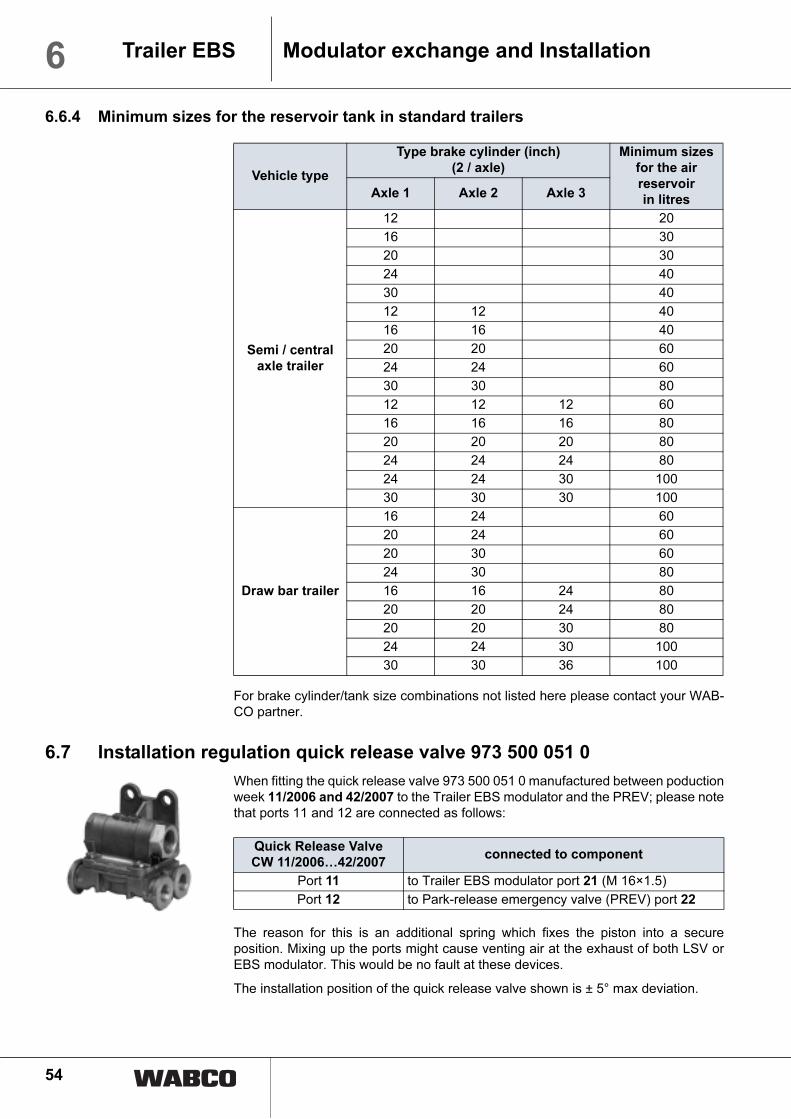
54
6 Trailer EBS Modulator exchange and Installation
6.6.4 Minimum sizes for the reservoir tank in standard trailers
For brake cylinder/tank size combinations not listed here please contact your WAB-CO partner.
6.7 Installation regulation quick release valve 973 500 051 0
When fitting the quick release valve 973 500 051 0 manufactured between poductionweek 11/2006 and 42/2007 to the Trailer EBS modulator and the PREV; please notethat ports 11 and 12 are connected as follows:
The reason for this is an additional spring which fixes the piston into a secureposition. Mixing up the ports might cause venting air at the exhaust of both LSV orEBS modulator. This would be no fault at these devices.
The installation position of the quick release valve shown is ± 5° max deviation.
Vehicle type
Type brake cylinder (inch)
(2 / axle)
Minimum sizes
for the air
reservoir
in litresAxle 1 Axle 2 Axle 3
Semi / central
axle trailer
12 20
16 30
20 30
24 40
30 40
12 12 40
16 16 40
20 20 60
24 24 60
30 30 80
12 12 12 60
16 16 16 80
20 20 20 80
24 24 24 80
24 24 30 100
30 30 30 100
Draw bar trailer
16 24 60
20 24 60
20 30 60
24 30 80
16 16 24 80
20 20 24 80
20 20 30 80
24 24 30 100
30 30 36 100
Quick Release Valve
CW 11/2006…42/2007connected to component
Port 11 to Trailer EBS modulator port 21 (M 16×1.5)
Port 12 to Park-release emergency valve (PREV) port 22
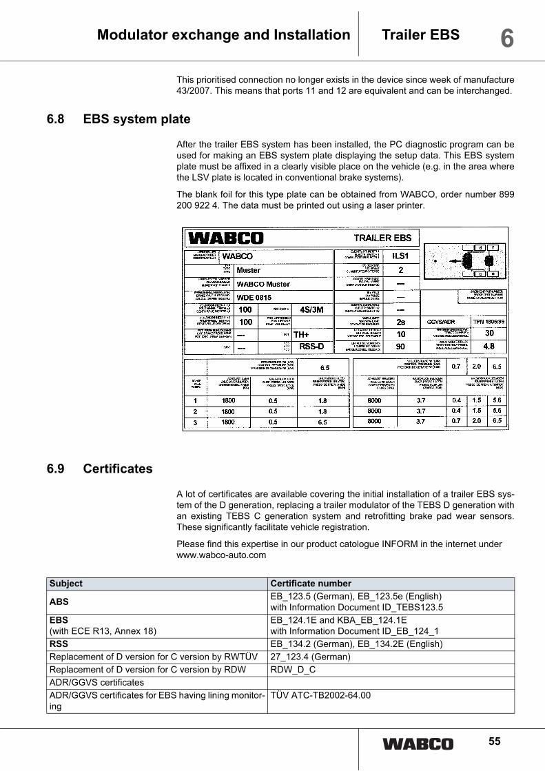
55
6Trailer EBSModulator exchange and Installation
This prioritised connection no longer exists in the device since week of manufacture43/2007. This means that ports 11 and 12 are equivalent and can be interchanged.
6.8 EBS system plate
After the trailer EBS system has been installed, the PC diagnostic program can beused for making an EBS system plate displaying the setup data. This EBS systemplate must be affixed in a clearly visible place on the vehicle (e.g. in the area wherethe LSV plate is located in conventional brake systems).
The blank foil for this type plate can be obtained from WABCO, order number 899200 922 4. The data must be printed out using a laser printer.
6.9 Certificates
A lot of certificates are available covering the initial installation of a trailer EBS sys-tem of the D generation, replacing a trailer modulator of the TEBS D generation withan existing TEBS C generation system and retrofitting brake pad wear sensors.These significantly facilitate vehicle registration.
Please find this expertise in our product catologue INFORM in the internet underwww.wabco-auto.com
Subject Certificate number
ABSEB_123.5 (German), EB_123.5e (English)with Information Document ID_TEBS123.5
EBS
(with ECE R13, Annex 18)EB_124.1E and KBA_EB_124.1Ewith Information Document ID_EB_124_1
RSS EB_134.2 (German), EB_134.2E (English)
Replacement of D version for C version by RWTÜV 27_123.4 (German)
Replacement of D version for C version by RDW RDW_D_C
ADR/GGVS certificates
ADR/GGVS certificates for EBS having lining monitor-ing
TÜV ATC-TB2002-64.00

56
6 Trailer EBS Modulator exchange and Installation
6.10 Trailer EBS test instruction - a tool for experts
Test Regulation What must be tested? How is the test done?Simul
ation
Response time 98/12/EC Annex III
ECE R13, Annex 6
Threshold time < 0.44 s
There are no requirements for the
trailer vehicle in regard of time re-
sponse behaviour.
With CTU:
Initial conditions:
• Set LSV to laden
• If necessary, set the brake narrow.
A
Power con-
sumption by
ABS - equiva-
lent actuations
98/12/EC Annex XIV After the number of equivalent ac-
tuations (ne) from the ABS certifi-
cate (§ 2.5), there must still be
pressure in the cylinder for a 22.5
% braking at the last brake actua-
tion.
TEBS-D:
Disc brake ne = 11
Drum brake ne = 10
VCS 1:
Disc brake ne = 16
Drum brake ne = 16
• Fill the trailer reservoir to 8 bar
• Shut off the supply
• At the yellow coupling head with
6.5 bar, brake with the number ne
• In the last actuation, hold the pres-
sure and measure the cylinder
pressure
Compare with the required pressure:
pH at z = 22.5 % from the brake cal-
culation page 1
A
Power con-
sumption by
spring-type
brake actuator
98/12/EG Annex V, §
2.4
ECE R13, Annex 8,
§2.4
Check if it is possible to release the
parking brake of the unhitched trail-
er at least three times.
• Support axle(s) with spring brakes
on blocks
• Charge the trailer to 6.5 bar reser-
voir pressure (7.5 bar for ECE ac-
ceptance)
• Unhitch the trailer
• autom. Release automatic braking
(black button)
• Exhaust and admit air into the
parking brake system (spring
brake) three times by pressing the
red button
• It must still be possible to turn the
wheels with spring-type brake ac-
tuators.
Start of braking
of spring-type
brake actuators
98/12/EG Annex V,
§2.5
ECE R13, Annex 8,
§2.5
This checks that the start of braking
of spring-type brake actuators is
not greater than the reservoir pres-
sure after 4 complete actuations.
• Ignition off
• Support axle(s) with spring brakes
on blocks
• Shut off the supply
• Charge the trailer to 6.5 bar reser-
voir pressure (7.0 bar for ECE ac-
ceptance)
• Exhaust and admit air into the
parking brake system (spring-type
brake actuator) by pressing the
red button until a wheel with a
spring-type brake actuator can no
longer be turned
• Measure the reservoir pressure
• Charge the trailer back up to 6.5
bar reservoir pressure (7.0 bar for
ECE acceptance)
• Actuate fully four times via the yel-
low coupling head
• Measure the reservoir pressure
The reservoir pressure at the start of
braking of the spring-type brake actu-
ators must be less than the reservoir
pressure after four complete actua-
tions.

57
6Trailer EBSModulator exchange and Installation
Measure the
brake forces on
all axles of an
unladen vehicle
on the roller dy-
namometer
The controlled braking forces of all
axles of an unladen vehicle are to
be measured.
The lifting axle is lifted and must be
lowered for the test.
B
LSV character-
istic when the
vehicle is sta-
tionary
The characteristic output by EBS
for the unladen or laden vehicle is
to be checked using a pressure
gauge.
• Connect a fine pressure control
valve and pressure gauge to the
yellow coupling head
• Connect a pressure gauge to the
brake cylinder test connection
• Supply the trailer with electrical
power
• Slowly increase the pressure us-
ing the fine control valve and
record the pressure gauge values.
C
Test Regulation What must be tested? How is the test done?Simul
ation
Simulation How to simulate? C generation D generation Note
A
Laden vehicle • Disconnect the axle load
sensor plug
• Connect a test valve to
connection 5 and simulate
laden bellows pressure
• Set the unladen braking
pressure to 6.5 bar in the
parameters (new startup
required at the end of the
measurements)
Set bellows pressure < 0.15
bar as follows
• Use rotary valve (ECAS...)
to lower onto blocks
• Connect a test valve to
connection 5 and simulate
laden bellows pressure
• Set the unladen braking
pressure to 6.5 bar in the
parameters (new startup
required at the end of the
measurements)
Reconnect the axle
load sensor plug
B
Lowering the lifted lift-
ing axle(s) of the unlad-
en vehicle.
Set an air suspension pres-
sure between 0.15 and 0.25
bar by
• Exhausting the supporting
bellows using the rotary
slide valve
• Connecting a pressure
simulation to the modula-
tor's port for bellow pres-
sure
• by PC diagnosis.
Set an air suspension pres-
sure between 0.15 and 0.25
bar by
• Exhausting the supporting
bellows using the rotary
slide valve
• Connecting a pressure
simulation to connection 5
of the modulator
• by PC diagnosis.
C
Test mode for checking
the LSV characteristic.
The emergency braking
function and standstill
function are switched
off in test mode.
Switch on the ignition / electri-
cal power supply with the ve-
hicle stationary and no
pressure at the yellow cou-
pling head.
Switch on the ignition / electri-
cal power supply with the ve-
hicle stationary and no
pressure at the yellow cou-
pling head.
Test mode is
switched off when the
vehicle is moved at
faster than 2.5 km/h.

58
7 Trailer EBS Appendix
7 Appendix
7.1
Fu
ncti
on
s /
servic
e f
or T
railer E
BS
/ t
railer m
od
ula
tor 4
80 1
02 …
0
* w
ith
Tra
iler
EB
S D
, p
ressu
re s
en
so
rs fo
r axle
load a
nd b
rake p
ressure
are
inte
gra
ted in the m
odula
tor
The p
ressure
sensor
may a
lso b
e u
sed d
uri
ng s
erv
icin
g if an
inte
rna
l d
em
an
d p
ressu
re s
en
so
r fa
ils.
WA
BC
O n
o.
48
0 1
02
...
...
00
0 0
...
00
1 0
...
00
2 0
...
00
4 0
...
00
5 0
...
01
0 0
...
01
4 0
...
01
5 0
TE
BS
G
en
era
tio
n
EB
S-C
2
to
we
ek
48
/01
EB
S-C
3
fro
m
we
ek
49
/01
EB
S-C
2
to
we
ek
48
/01
EB
S-C
3
fro
m
we
ek
49
/01
EB
S-C
2
to
we
ek
48
/01
EB
S-C
3
fro
m
we
ek
49
/01
EB
S-C
3
fro
m
we
ek
49
/01
EB
S-C
3
fro
m
we
ek
49
/01
EB
S-D
fro
m
we
ek
44
/02
EB
S-D
fro
m
we
ek
44
/02
EB
S-D
fro
m
we
ek
44
/02
AB
S
co
nfig
ura
tio
n
4S
/3M
4S
/3M
4S
/3M
4S
/3M
4S
/3M
4S
/3M
4S
/3M
4S
/3M
4S
/2M
4S
/3M
4S
/3M
Ba
tte
ry
ch
arg
eX
XX
X
TC
EX
XX
X
RS
SX
XX
X
We
ar
inp
ut
XX
XX
XX
X
Sw
itch
ing
ou
tpu
t 1
XX
XX
XX
X
Sw
itch
ing
ou
tpu
t 2
XX
XX
XX
X
ILS
XX
XX
XX
X
Axle
lo
ad
se
nso
r
44
1 0
40
...
...0
07
0
...0
13
0
...0
15
0
...0
07
0
...0
13
0
...0
15
0
...0
07
0
...0
13
0
...0
15
0
...0
07
0
...0
13
0
...0
15
0
...0
07
0
...0
13
0
...0
15
0
...0
07
0
...0
13
0
...0
15
0
...0
07
0
...0
13
0
...0
15
0
...0
07
0
...0
13
0
...0
15
0
44
1 0
44
10
1 0
/
10
2 0
*
44
1 0
44
10
1 0
/
10
2 0
*
44
1 0
44
10
1 0
/
10
2 0
*
Ext.
Bra
ke
pre
ssu
re
se
nso
r
44
1 0
40
...
...0
07
0
...0
13
0
...0
15
0
...0
07
0
...0
13
0
...0
15
0
...0
07
0
...0
13
0
...0
15
0
...0
07
0
...0
13
0
...0
15
0
...0
07
0
...0
13
0
...0
15
0
44
1 0
44
10
1 0
/
10
2 0
*
44
1 0
44
10
1 0
/
10
2 0
*
Tra
iler
em
erg
en
cy
va
lve
97
1 0
02
...
...8
02
0..
.80
2 0
...3
01
0
...8
02
0..
.80
2 0
...3
01
...8
02
0..
.80
2 0
...3
01
...8
02
0
...3
01
...8
02
0
...3
01
...3
01
0
(...
PR
EV
up
fro
m
III/
03
)
...3
01
0
(...
PR
EV
up
fro
m
III/
03
)
...3
01
0
(...
PR
EV
up
fro
m
III/
03
)
Ca
n b
e
rep
lace
d b
y
AH
M 4
80
10
2 .
..
...
01
4 0
(...
01
0 0
on
ly f
or
4S
/2M
)
...
01
4 0
(...
01
0 0
on
ly f
or
4S
/2M
)
...
01
4 0
...
01
4 0
...
01
5 0
...
01
5 0
...
01
4 0
...
01
5 0
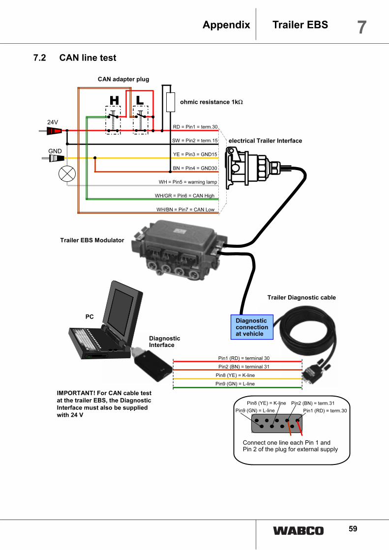
59
7Trailer EBSAppendix
7.2 CAN line test
24V
GND
CAN adapter plug
YE = Pin3 = GND15
BN = Pin4 = GND30
WH = Pin5 = warning lamp
RD = Pin1 = term.30
SW = Pin2 = term.15
WH/GR = Pin6 = CAN High
WH/BN = Pin7 = CAN Low
H L
IMPORTANT! For CAN cable test
at the trailer EBS, the Diagnostic
Interface must also be supplied
with 24 V
electrical Trailer Interface
Trailer EBS Modulator
PC
DiagnosticInterface
Diagnosticconnectionat vehicle
Trailer Diagnostic cable
Pin2 (BN) = term.31
Pin1 (RD) = term.30Pin9 (GN) = L-line
Pin8 (YE) = K-line
Connect one line each Pin 1 and Pin 2 of the plug for external supply
Pin1 (RD) = terminal 30
Pin2 (BN) = terminal 31
Pin9 (GN) = L-line
Pin8 (YE) = K-line
ohmic resistance 1kΩ

60
7 Trailer EBS Appendix
7.3 Parameter settings for lifting axle control on a semitrailer
Desired lifting
axle function
PC diagnosis "EBS parameters"
Page 1 Page 2 Page 3
Lifting
axles
ILS1 ILS2 IN/OUT1 Speed "Lift-
ing axle
raise"
(km/h)
Percentage
axle load lift-
ing axle low-
er (%)
Traction
help pres-
sure restric-
tion (bar)
stop of trac-
tion help
(km/h)
Lift axle control
1 One lifting axle; raise
while standstill
X X 0 max. 100
2 One lifting axle; raise
while ride
X X 20 max. 100
3 Two parallel lifting
axles; raise while
standstill
X X 0 max. 100
4 Two parallel lifting
axles; raise while
ride
X X 20 max. 100
5 Two separate lifting
axles; raise while
standstill
X X X 0 max. 100
6 Two separate lifting
axles; raise while
ride
X X X 20 max. 100
Traction help
7 One lifting axle X X TH 0…30 max. 100 1.3× bellow
pressure,
loaden
30
8 One lifting axle with
residual pressure
holding (additional
solenoid valve)
X X TH(+) 0…30 max. 100 1.3× bellow
pressure,
loaden
30
9 Two separate lifting
axles (ILS1 at LA 1)
X X X TH 0…30 max. 100 1.3× bellow
pressure,
loaden
30
Special cases
10 Only constrained
lowering / no traction
help
X X TH 0…30 max. 100 0 0
11 Only Traction Help /
no lifting axle func-
tion
X X TH or
TH(+)
0 10 1.3× bellow
pressure,
loaden
30

61
7Trailer EBSAppendix
7.4 Parameters load sensing
Relationship axle load/bellows pressure/brake pressure semi trailer
LSV function in the semi trailer
1 3
4
5
678 9 2
p bellow/loaden =
3.7
bar
pbellow/empty
= 0.5 bar
Brake pressure pm [bar]
= pressure coupling head yellow
Bra
ke p
ressure
pB [bar]
= p
ressure
wheel bra
ke c
ylin
der
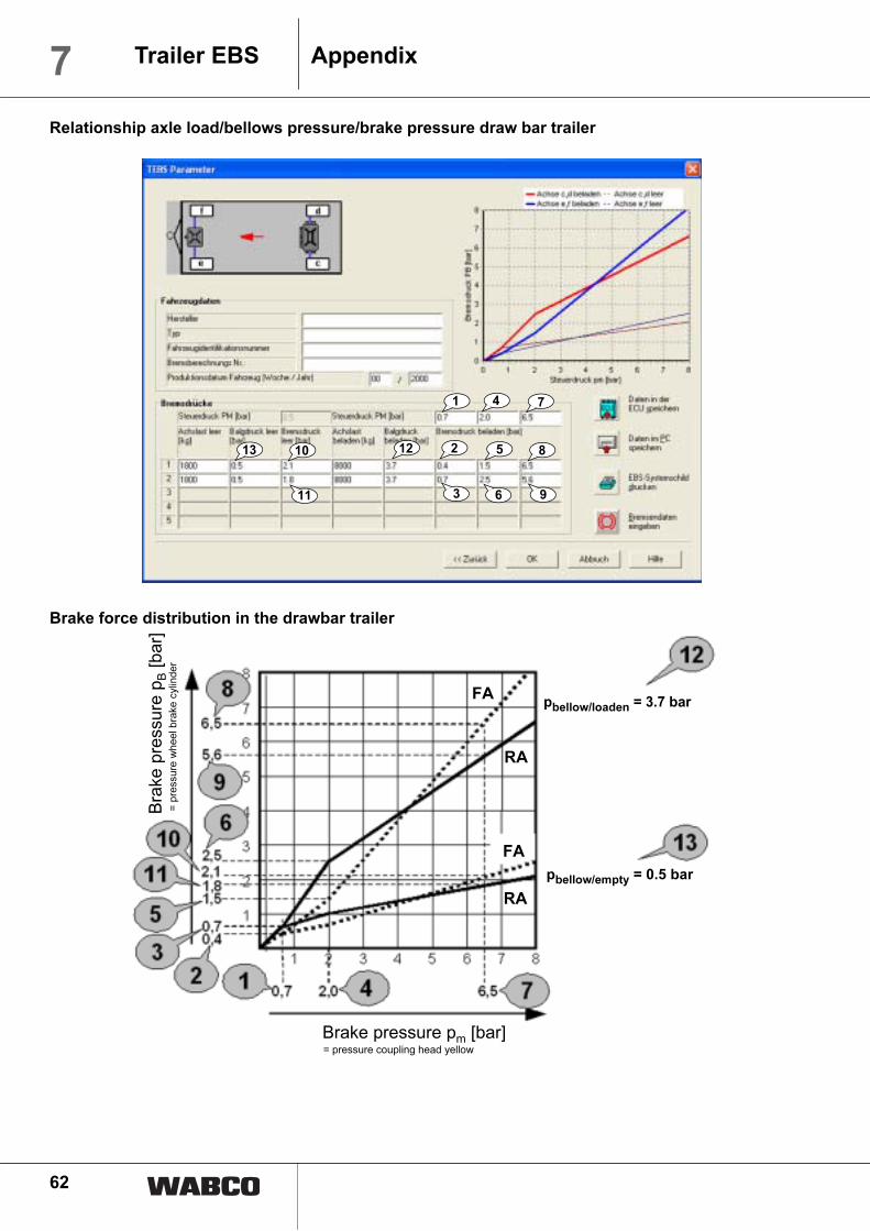
62
7 Trailer EBS Appendix
Relationship axle load/bellows pressure/brake pressure draw bar trailer
Brake force distribution in the drawbar trailer
1
11
4
510
7
813 2
3 6 9
12
pbellow/loaden = 3.7 bar
pbellow/empty = 0.5 bar
Brake pressure pm [bar]
= pressure coupling head yellow
Bra
ke p
ressure
pB [bar]
= p
ressure
wheel bra
ke c
ylin
der
FA
RA
FA
RA

63
7Trailer EBSAppendix
7.5 Lifting Axle Circuit
Lifting axle dual circuit
Lifting axle dual circuitTraction help
1234 57 68
20
2122
2423
1 2 2 1
41 1
4 3 2 1
8 7
1234
7 6 56 5
X 2 X 1
BN
BL
RD
BN
WH
to the Levelling valve
EBS-Electronic
463 084 010 0
449 624 ... 0 PIN 4
EBS DIAG-K
PIN 7
GND
PIN 1
+24V
DIA./ILS/ISS POWER
4 3 2 1
8 7
1234
7 6 56 5
12 34 57 68
20
2122
24 23
1 2 2 1
41 1
X 2 X 1
31
2
1
2
3
+
-
24 V
24 V
EBS-Electronic
Pay attention to parameters!
please consider ISO 12098 wiring
please consider truck wiring
Cable will not be connected
Switching optionalswitching to minus
switching to plus
button traction help:
press less than 5 sec. = start traction help
press > 5 sec. = constrained lowering
Levelling valve
BN
BL
RD
BN
WHBKBN
463 084 010 0
PIN 4
EBS DIAG-K
PIN 7
GND
PIN 1
+24V
DIA./ILS/ISS POWER
449 624 ... 0
449 762 ... 0
X 5
IN / OUT 1

64
7 Trailer EBS Appendix
Lifting axle single circuit Traction help
Lifting axle single circuitTraction help, stop light input
4 3 2 1
8 7
1234
7 6 56 5
12 34 57 681 2 2 1 21
1222
1
3
X 2 X 1
31
2
1
2
3
+
-
24 V
24 V
ILS 2
GND
ILS 1
RD
RD
BN
WH
BKBN
YE
WH
EBS-Electronic
Pay attention to parameters!
please consider ISO 12098 wiring
please consider truck wiring
Cable will not be connected
Switching optionalswitching to minus
button traction help:
press less than 5 sec. = start traction help
press > 5 sec. = constrained lowering
Levelling valve
463 084 030 0
PIN 4
EBS DIAG-KPIN 7
GND
PIN 1
+24V
DIA./ILS/ISS POWER
449 664 ... 0
449 762 ... 0
X 5
IN / OUT 1
switching to plus
4 3 2 1
8 7
1234
7 6 56 5
12 34 57 681 2 2 1 21
1222
1
3
X 2 X 1
31
2
1
2
3
+
-
24 V
24 V
stop light
input RD
RD
BN
WH
BKBN
BL BN
BL
BN
GN
EBS-Electronic
Pay attention to parameters!
please consider ISO 12098 wiring
please consider truck wiring
Switching optionalswitching to minus
button traction help:
press less than 5 sec. = start traction help
press > 5 sec. = constrained lowering
Levelling valve
463 084 030 0
PIN 4
EBS DIAG-K
PIN 7
GND
PIN 1
+24V
DIA./ILS/ISS POWER
449 684 ... 0
449 762 ... 0
X 5
IN / OUT 1
switching to plus
449 742 ... 0
Cable will not be connected

65
7Trailer EBSAppendix
Lifting axle single circuitTraction help with residual pressure holding
4 3 2 1
8 7
1234
7 6 56 5
12 34 57 681 2 2 1 21
1222
1
3
X 2 X 1
31
2
1
2
3
+ +
2 1
3
+
-
24 V
24 V
GND
ILS 1
ILS 2
RD
RD
BN
WHBK
BN
YE
BN
BK
WH
EBS-Electronic
Pay attention to parameters!
please consider ISO 12098 wiring
please consider truck wiring
Switching optionalswitching to minus
button traction help:
press less than 5 sec. = start traction help
press > 5 sec. = constrained lowering
Levelling valve
463 084 030 0
PIN 4
EBS DIAG-K
PIN 7
GND
PIN 1
+24V
DIA./ILS/ISS POWER
449 664 ... 0
449 764 ... 0
switching to plus
Cable will not be connected
X 5
IN / OUT 1

66
7 Trailer EBS Appendix
7.6 Braking system diagram Trailer EBS CTrailer EBS C: Central axle trailer 2-axle 4S/2M and 2S/2M

67
7Trailer EBSAppendix
Trailer EBS C: 2-axle drawbar trailer 4S/3M

68
7 Trailer EBS Appendix
Trailer EBS C: Semi trailer 3-axle 4S/2M and 2S/2M

69
7Trailer EBSAppendix
Trailer EBS C: Semi trailer 3-axle 4S/2M + 1M

70
7 Trailer EBS Appendix
Trailer EBS C: 3-axle semitrailer 4S/3M

71
7Trailer EBSAppendix
Trailer EBS C: Installation diagram 4S/3M

72
7 Trailer EBS Appendix
Trailer EBS C: Installation diagram 4S/2M

73
7Trailer EBSAppendix
Trailer EBS C: Installation diagram 4S/2M +1M

74
7 Trailer EBS Appendix
7.7 Braking system diagram Trailer EBS D
Trailer EBS D+: 3 axle semitrailer 4S/2M or 2S/2M with PREV and 2-way valve

75
7Trailer EBSAppendix
Trailer EBS D+: 3 axle semitrailer 4S/2M or 2S/2M with PREV and overload protection valve

76
7 Trailer EBS Appendix
Trailer EBS D+: 2 axle draw bar 4S/3M with PREV and 2-way valve

77
7Trailer EBSAppendix
Trailer EBS D: 3 axle semitrailer 4S/2M or 2S/2M with trailer emergency valve, double release valve
and and 2-way valve
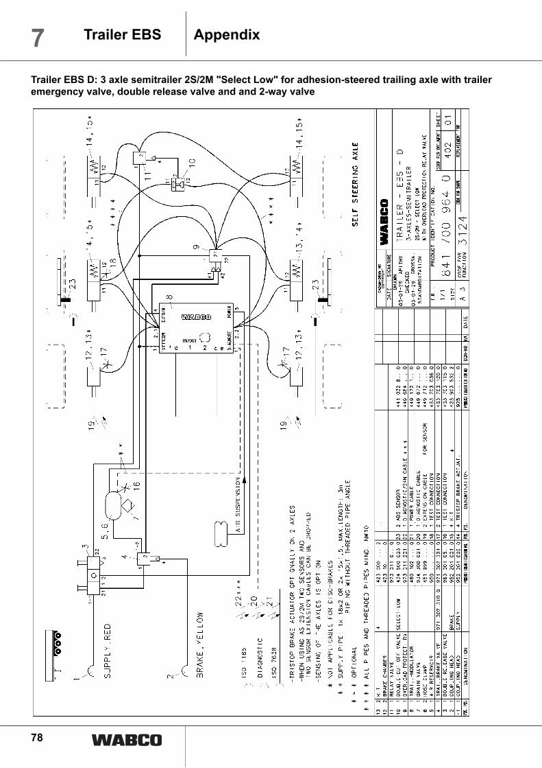
78
7 Trailer EBS Appendix
Trailer EBS D: 3 axle semitrailer 2S/2M "Select Low" for adhesion-steered trailing axle with trailer
emergency valve, double release valve and and 2-way valve

79
7Trailer EBSAppendix
Trailer EBS D: 3 axle semitrailer 4S/3M with trailer emergency valve, double release valve and 2-way
valve

80
7 Trailer EBS Appendix
Trailer EBS D with TCE: 3 axle semitrailer 4S/2M or 2S/2M with trailer emergency valve, double
release valve and and 2-way valve