Embed Size (px)
Citation preview

TRAIL CONSULTING GROUP, PLLC
TRAIL CONSULTING GROUP, PLLC 12630 North 79th Street, Scottsdale, Arizona 85260 Phone: (602) 476-1021 E-mail: [email protected]
April 19, 2017
Ms. Carmen Parks, P.E. Morrison Maierle 3202 East Harbour Drive Phoenix, Arizona 85034 TCG-16-008.1 Re: Elliot District Park – Big League Dreams
Grandstand Anchor Bolts
Ms. Parks,
Per our previous discussions, TCG has prepared the following summary of the situation at the Grandstand framing recently uncovered by the destructive testing. TCG offers the following comments:
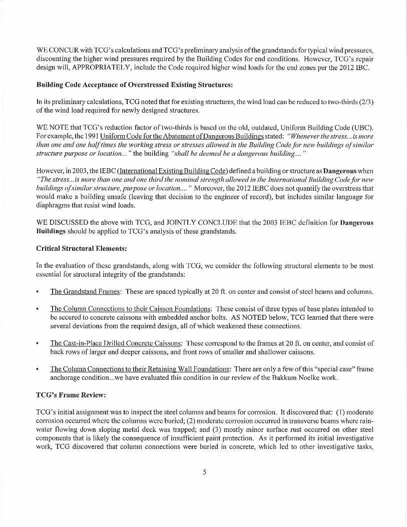
1. The concrete covering the anchor bolts was removed at eight locations. Eight anchor bolts were pull tested.
2. When the anchor bolts were exposed, they were found to be uniformly smaller in diameter than the bolts specified on the Record Drawings. The typical bolt was found to be 7/8 inch in diameter compared to the 1 1/8 inch diameter bolt required by the Record Drawings (as a “best case” scenario, the bolts would be “reduced diameter body style” bolts of one inch diameter, with an often less than the specified minimum body diameter, resulting in an effective 7/8 inch diameter bolt). This corresponds to roughly a forty (40) percent reduction in the strength of the column base connection beyond what was known prior to the testing.
3. At locations where repairs had been made during original construction (due to a deficiency in the originally installed bolt diameter), the supplemental bolts added during original construction were also 7/8 inch diameter bolts, smaller than the 1 1/8 inch diameter bolts required by the record drawings.
4. The embedment of the post (epoxy) installed anchor bolts was not consistent, with most locations showing a high probability of deficient embedment. This was evident by the variable and often excessive height of the bolt protrusion above the base plate. Lack of embedment negatively affects the capacity of the bolt.
5. One of the eight bolts (about 13%) that were tested failed the pull test when a minimal tension force (40 pounds) was applied. Epoxy was observed at the base of this anchor bolt, indicating that the bolt was installed after the concrete was placed. The failed connector reduces the capacity of the column base connection by an additional thirty-three (33) percent.
6. At three of the eight locations tested (and at other visible bolts that were not tested), epoxy was evident on the base of the anchor bolts. It is possible that epoxy installed anchor bolts were present at other test locations but the presence of epoxy was not evident.
7. Some level of corrosion was found on most steel columns, base plates, anchor bolts, nuts, and washers at most locations. The quantity of corrosion varied from relatively minor surface corrosion to a loss of cross section of about 1/16 inch of flange thickness denoted by flaking of corrosion by-products from the steel column surface.
8. Additional installation inconsistencies were noted, including exposed caisson reinforcing, omitted or loose leveling nuts, and/or omitted or incomplete corrosion protection.
The net result of the recently discovered bolt diameter deficiencies is that the capacity of the as-built anchor bolts is, at best, about forty (40) percent less than the capacity that would have been present had the correct bolt diameter been provided. This reduction is absent consideration of any of the other deficiencies noted during the testing.

The configuration of the bolts was also changed from the layout shown on the record drawings (two rows of three bolts vs. three rows of two bolts) at the larger W14x120 columns. This change further reduces the provided strength at these locations by thirty-three (33) percent, a net capacity reduction of about seventy-three (73) percent from the connection shown on the Record Drawings.
These bolt deficiencies, combined with a deficiency in the supporting caissons to resist the required loads, adds substantially to the previously known deficiency at these column base locations and requires a rethinking of the repair protocol and an expansion of the quantity of frames that will require repair. The amount of overstress that is now known to exist means that it is not practical to just strengthen the uphill column base sufficiently to resist the required loads.
Consequently, the Design Team is investigating alternate repair methodologies to strengthen the system to behave as a series of frames. Although apparently not included as part of the original structural design, frame action can distribute a portion of the forces to other elements. This redistribution of forces has the benefit of substantially reducing the stress on the deficient column base connections, but has the cost of increasing loads in other elements that were not originally designed to resist those forces.
After exploring many potential repair methodologies, the current anticipated repair methodology is to utilize steel rods, plates, and turnbuckles to provide X-bracing between the downhill and uphill caisson and sloped steel member that frames between the uphill and downhill columns. This bracing will be hidden beneath the grandstand murals. It will also be necessary to strengthen some of the caissons by introducing helical piers as a supplemental support to resist both vertical and horizontal frame forces. These piers will also be hidden from view.
In addition, due to the combination of deficiencies, many of the existing conditions can be classified by the Building Code as “Dangerous.” This classification results in a Building Code mandated need to repair or remove the offending structure.
As we have discussed, there is a substantial amount of additional structural engineering analysis and design work that is required to attempt to mitigate the impact of these additional deficiencies. This additional work is outside the scope of our current contract. As you are aware, we have continued with this additional work in an effort minimize the impact on the Project schedule.
We appreciate the opportunity to provide this service. Please call if you have any questions.
Sincerely,
TRAIL CONSULTING GROUP, PLLC Steven E. Trail, P.E. Principal
4/19/2017
6/30/2019