Embed Size (px)
Citation preview

Section 4: Temporary Traffic Control Devices
Traffic Management Manual for Work on Roadways December 2015 4-i
PART B – TRAFFIC CONTROL
Section 4: Temporary Traffic Control Devices
Contents
4.1 Introduction ................................................................................................. 4-1
4.1.1 Fundamental Principles ................................................................... 4-1 4.1.2 Safety Standards for Traffic Control Devices .................................. 4-2 4.1.3 General Requirements for Traffic Control Devices ......................... 4-2 4.2 Traffic Signs ................................................................................................ 4-3
4.2.1 General Guidelines for Traffic Signs ............................................... 4-3 4.2.2 Standard Sign Patterns ................................................................... 4-3 4.2.3 Sign Material .................................................................................... 4-3 4.2.4 Retroreflectivity Standards .............................................................. 4-4 4.2.5 Sign Dimensions and Letter Heights ............................................... 4-5 4.2.6 Sign Supports .................................................................................. 4-6 4.2.7 Sign Selection .................................................................................. 4-9 4.2.8 Sign Placement and Spacing .......................................................... 4-9 4.3 Dynamic Message Signs (DMS) .............................................................. 4-10
4.3.1 Permanently-Mounted DMS .......................................................... 4-10 4.3.2 Portable DMS ................................................................................ 4-10 4.3.3 DMS Fundamentals ....................................................................... 4-11 1. Abbreviated Messages .......................................................... 4-11 2. DMS Placement .................................................................... 4-12 3. Message Guidelines .............................................................. 4-13 4. Operational Guidelines .......................................................... 4-14 5. Message Types and Categories ........................................... 4-15
4.4 Pavement Markings .................................................................................. 4-16
4.4.1 Removal of Pavement Markings ................................................... 4-16 4.4.2 Temporary Pavement Markings .................................................... 4-18 4.4.3 Temporary Overlay Markers (TOMs) ............................................ 4-20

Section 4: Temporary Traffic Control Devices
Traffic Management Manual for Work on Roadways December 2015 4-ii
4.5 Channelizing Devices .............................................................................. 4-21
4.5.1 Cones ............................................................................................ 4-23 4.5.2 Tubular Markers (Tubes) .............................................................. 4-24 4.5.3 Drums/Barrels ............................................................................... 4-25 4.5.4 Surface-Mounted Delineators ....................................................... 4-26 4.5.5 Post-Mounted Delineators ............................................................ 4-26 4.5.6 Vertical Panels .............................................................................. 4-27 4.5.7 Barricades ..................................................................................... 4-28 4.5.8 Temporary Roadside/Median Barriers .......................................... 4-30 4.5.9 Temporary Lane Separators ......................................................... 4-31 4.5.10 Longitudinal Channelizing Devices ............................................... 4-32 4.5.11 Other Channelizing Devices ......................................................... 4-32 4.6 Flashing Arrow Boards (FABs) ............................................................... 4-33
4.6.1 FAB Specifications ........................................................................ 4-33 1. Types .................................................................................... 4-33 2. Minimum Requirements ........................................................ 4-34 3. Visibility and Light Intensity ................................................... 4-34 4. Display Options ..................................................................... 4-35 4.6.2 FAB Setup ..................................................................................... 4-35 4.6.3 FAB Operation .............................................................................. 4-36 4.6.4 Arrow Sticks .................................................................................. 4-36 4.7 Automated Flagger Assistance Devices (AFADs) ................................ 4-37
4.7.1 Operation Modes .......................................................................... 4-37 4.7.2 Deployment Guidelines ................................................................. 4-38 4.7.3 Equipment Requirements ............................................................. 4-38 4.7.4 AFAD Placement and Operating Options ..................................... 4-39 4.8 Portable Traffic Signals ........................................................................... 4-40
4.8.1 Deployment Guidelines ................................................................. 4-40 4.8.2 Operational Guidelines ................................................................. 4-41 4.8.3 Portable Traffic Signal Timing Plan............................................... 4-43 Category 2 Actuated Traffic Signal Timing Plan ........................ 4-44 Example of Actuated Portable Traffic Signal Timing Calculations ................................................................... 4-45 4.9 Lighting Devices ...................................................................................... 4-46
4.9.1 Flashing Vehicle Lights ................................................................. 4-46 4.9.2 Yellow Warning Lights .................................................................. 4-46 4.9.4 Roadway Lighting ......................................................................... 4-47 4.9.5 Overhead Lighting ......................................................................... 4-48 4.9.6 Equipment Lighting ....................................................................... 4-48 4.10 Fencing and Screens ............................................................................... 4-49
4.10.1 Work Zone Fencing ....................................................................... 4-49 4.10.2 Work Zone Screens and Barrier Screens ..................................... 4-50
Section 4: Temporary Traffic Control Devices
Traffic Management Manual for Work on Roadways December 2015 4-iii
4.11 Other Traffic Control Devices ................................................................. 4-51
4.11.1 Flags on Traffic Control Devices ................................................... 4-51 4.11.2 Sand Bags/Weights ....................................................................... 4-52 4.11.3 Speed Reader Boards ................................................................... 4-52 1. Deployment Guidelines ......................................................... 4-52 2. Operational Guidelines .......................................................... 4-53 4.11.4 Temporary Rumble Strips.............................................................. 4-56 4.11.5 Shadow Vehicles ........................................................................... 4-58 4.11.6 Buffer Vehicles .............................................................................. 4-59 4.11.7 Vehicle-Mounted Crash Attenuators ............................................. 4-59 4.11.8 Temporary Crash Attenuators on Barriers .................................... 4-60 4.11.9 Pilot Cars for Work Zones ............................................................. 4-61 1. Communication with Stakeholders ........................................ 4-61 2. Planning and Operations ....................................................... 4-61 3. Pilot Car Warning Lights ........................................................ 4-62 4. Pilot Car Signs ....................................................................... 4-62 5. Pilot Car Radio Communications .......................................... 4-63 6. Pilot Car Traffic Control ......................................................... 4-63

Section 4: Temporary Traffic Control Devices
Traffic Management Manual for Work on Roadways December 2015 4-iv
This page is intentionally blank.
Section 4: Temporary Traffic Control Devices
Traffic Management Manual for Work on Roadways December 2015 4-1
PART B – TRAFFIC CONTROL
Section 4: Temporary Traffic Control Devices
4.1 Introduction
Temporary traffic control devices are:
Signs, signals, markings, and other devices used to regulate, warn, and guide road users through or around roadway construction, maintenance, or utility work.
The design and application of temporary traffic control devices in work zones should address the needs of all road users—drivers, cyclists, and pedestrians, including those with disabilities. The devices should meet the basic principles of signing to be effective with road users:
1. They fulfill a need.
2. They command attention and respect.
3. They convey a clear, simple meaning.
4. They provide adequate time for a proper response.
These Ministry manuals provide additional information on using traffic control devices:
Electrical and Traffic Engineering Manual, 2013
Manual of Standard Traffic Signs and Pavement Markings, 2000
4.1.1 Fundamental Principles
1. Regulatory devices are those specified by Provincial statute and/or municipal by-law, and are used to require certain actions of drivers, cyclists, and pedestrians.
2. Consistent sign design assists in communicating information to drivers and enables road users to recognize and easily understand what is required. Signs should have the same shape, colour, dimensions, messaging, and retroreflectivity as signs of the same type.
3. Uniformity means always treating similar situations in the same way. Placing devices in a uniform and consistent manner ensures that road users can respond properly based on their previous exposure to similar traffic control situations.
4. Sign placement should ensure visibility and adequate time for road users to respond to the messaging.
5. Physical maintenance is required to ensure that devices are visible and legible. Clean and properly mounted devices, in good condition, command the respect of road users.
6. Functional maintenance means installing, adjusting, and removing traffic control devices in response to changing roadway conditions. This includes review of the traffic control plan for effectiveness and modification if necessary.
Section 4: Temporary Traffic Control Devices
Traffic Management Manual for Work on Roadways December 2015 4-2
4.1.2 Safety Standards for Temporary Traffic Control Devices Ministry policy requires that all roadside devices such as traffic barriers, barrier terminals, crash attenuators, bridge railings, sign and light pole supports, and work zone hardware used on Provincial highways meet the crash-worthy performance criteria specified in National Cooperative Highway Research Program (NCHRP) Report 350: Recommended Procedures for the Safety Performance Evaluation of Highway Features.
4.1.3 General Requirements for Temporary Traffic Control Devices Temporary traffic control devices used for construction, maintenance, utility or incident
management operations on a street, highway, or private road open to public travel shall comply with the applicable provisions of this Manual.
Devices shall be maintained and kept clean, visible, and properly positioned at all times.
Devices that are excessively worn, bent, or damaged shall be replaced.
Devices that have lost a significant amount of retroreflectivity shall be replaced.
Cones shall be retroreflective if used at night.
Any contract provisions regarding temporary traffic control devices shall be implemented as specified.
Section 4: Temporary Traffic Control Devices
Traffic Management Manual for Work on Roadways December 2015 4-3
4.2 Traffic Signs
This section explains the use of standard traffic signs for construction, maintenance, and utility work. Specific information on the individual signs commonly used in construction and maintenance applications—including sign illustrations and descriptions—is provided in Appendix B: Standard Construction Signs.
4.2.1 General Guidelines for Traffic Signs
Construction signs are fluorescent orange.
Other traffic signs may be used within work zones including regulatory, warning, and guide signs. Warning signs within work zones are fluorescent orange.
Existing signs that do not apply during the work activity shall be covered or removed.
See Appendix B: Standard Construction Signs for the most commonly used signs for work zones.
4.2.2 Standard Sign Patterns
The sign illustrations in this Manual are only representations of the true designs, and should not be used as patterns for sign manufacturing. The Ministry’s Catalogue of Standard Traffic Signs provides information regarding the signs used by the Ministry:
http://www.th.gov.bc.ca/publications/eng_publications/geomet/geometsigns.htm 4.2.3 Sign Material
1. Rigid Signs
Rigid signs are sufficiently rigid to display the sign information to road users for the duration of work under all road and climatic conditions. They are the most common type of sign on Provincial Highways. Rigid work zone signs are typically made of aluminum or plywood. They may also be fabricated using alternative substrate material (fiberglass, plastic, composites, etc.), provided that sign performance (visibility, sheeting adhesion) matches that of aluminum or plywood. Traffic control paddles can also use alternative substrates.
2. Roll-Up Signs
Roll-up signs are made from flexible sheeting material that allows them to be rolled-up or folded. They are usually mounted on lightweight supports. The mounting should be such that the sign display is similar to that of a rigid signs. Any roll-up sign that meets the following criteria is suitable for use on Provincial highways for work not exceeding 48 hours in duration (including overnight).

Section 4: Temporary Traffic Control Devices
Traffic Management Manual for Work on Roadways December 2015 4-4
4.2.4 Retroreflectivity Standards 1. Signs shall show the same colours and shapes by night as by day.
2. Ministry sign and device retroreflectivity shall conform to the American Society for Testing and Materials (ASTM) D 4956 Standard Specification for Retroreflective Sheeting for Traffic Control.
All fluorescent orange signs, barricades, vertical panels, and rigid, flat surfaces shall have retroreflectivity using ASTM Type 9 or better sheeting.
All rigid, flat surface signs of other colours shall have retroreflectivity in accordance with the Ministry’s Catalogue of Standard Traffic Signs (typically, ASTM Type 3/4 sheeting).
All flexible or curved surfaces, such as the surfaces of roll-up signs, drums, or tubular markers, shall have retroreflectivity using ASTM Type 6 or better sheeting material.
3. Signs should be inspected to ensure proper retroreflectivity. This may be done by driving through the work zone at night using only low-beam headlights and assessing the legibility of each sign. The retroreflectivity levels of signs may also be checked using a photometer or reflectometer.
Generally, signs should be replaced when they show a 50% loss of retroreflectivity based on the manufacturer’s specification.
4. Work zone signs are subject to severe service conditions and generally have a shorter life expectancy than permanently mounted signs. Signs that are visibly damaged, cracked, glazed, pitted, or otherwise marred to the extent that they are ineffective should be replaced immediately.

Section 4: Temporary Traffic Control Devices
Traffic Management Manual for Work on Roadways December 2015 4-5
4.2.5 Sign Dimensions and Letter Heights
1. The Ministry’s Catalogue of Standard Traffic Signs specifies sign dimensions and letter heights of construction signs.
2. Sign sizes used in work zones should not be smaller than those normally required on the roadway.
3. Sign sizes are related to the roadway type—local road, low-speed road, arterial road, expressway, or freeway:
Smaller dimensions apply to urban roadways where the regular posted speed is ≤ 60 km/h.
Larger dimensions apply to rural roadways with a regular posted speed limit of ≥70km/h, provided that there is sufficient room to accommodate the larger signs.
Multilane divided roadways typically use oversized signs on both the right and the left side of the roadway. Signs erected on the left side may be erected in a closed lane, shoulder, or median. If sufficient width is not available on the left shoulder or median, a smaller sized sign may be used.
4. Custom signs may be required to convey site-specific information. The recommended letter heights shown below should be used when designing these signs.
Table 4.1: Recommended Letter Heights for Custom Construction Signs
Recommended Letter Heights for Custom Construction Signs
≤ 50 km/h 150 mm
60 - 90 km/h 200 mm
> 90 km/h 250 mm (minimum)
300 mm (desirable)

Section 4: Temporary Traffic Control Devices
Traffic Management Manual for Work on Roadways December 2015 4-6
4.2.6 Sign Supports 1. Signs may be attached to posts or portable supports. For long-duration projects, signs
are typically post-mounted.
2. Temporary STOP and YIELD signs should be mounted at approximately the same height and in approximately the same position as permanent installations.
3. Portable sign supports are more practical for short-duration work and for situations in which signs are repositioned frequently.
4. Sign supports should be lightweight, yielding, or have the same breakaway features as permanent installations.
5. To avoid illegibility resulting from the glare and direct reflection of headlights, signs may be tilted back slightly or rotated a few degrees away from the roadway but the sign message shall remain clearly displayed to drivers.
6. Post-Mounted Sign Supports: Minimum mounting heights and lateral offsets for post-mounted signs are shown in Figure 4.1 A: Typical Sign Installation Heights and Offsets.
7. Signs up to 90 cm x 90 cm may be mounted on one post. Larger signs normally require two posts.
8. Portable Sign Supports: For posted speeds ≥ 70 km/h, signs should be mounted 1.5 metres from the ground (to the bottom of the sign) on a crash-worthy portable sign support as shown in Figure 4.1 B: Typical Sign Installation on Wind-Resistant Sign Stand. Signs shall be mounted at least 30 cm from the ground.
9. For speeds < 70 km/h, signs may be mounted less than 30 cm from the ground.
10. A lateral clearance of 60 cm should be maintained between the edge of the sign on a temporary support and the travelled way.
11. Consider the type and placement of sign supports when working around sidewalks, bicycle facilities, or areas designated for pedestrian or bicycle traffic.

Section 4: Temporary Traffic Control Devices
Traffic Management Manual for Work on Roadways December 2015 4-7
Figure 4.1 A: Typical Sign Installation Heights and Offsets
TRAV
ELLE
D RO
ADW
AYED
GE
1.8 –3.6 m
ELEVATION OF TRAVELLED ROAD- WAY EDGE
1.5 m min.1.2 m min.
NO CURB AND GUTTER
CURB and GUTTER TEMPORARY SUPPORT
TRAV
ELLE
D RO
ADW
AYED
GE
TRAV
ELLE
D RO
ADW
AYED
GE
2.1 m min.30 cm min.
60 cmmin.

Section 4: Temporary Traffic Control Devices
Traffic Management Manual for Work on Roadways December 2015 4-8
Figure 4.1 B: Typical Sign Installation on Wind-Resistant Sign Stand
1.5 mTyp.
Section 4: Temporary Traffic Control Devices
Traffic Management Manual for Work on Roadways December 2015 4-9
4.2.7 Sign Selection The standard signs shown in Appendix B: Standard Construction Signs should be used wherever possible. Custom signs should be approved by the Road Authority. Select the appropriate layout in Sections 7 to 19 that best describes the work.
4.2.8 Sign Placement and Spacing
Recommended advance placement distances for initial signs, and distances between subsequent signs in a series, are shown as dimensions in Table A – Taper Lengths and Table B – Device Spacing Lengths (see Section 6.6 or Appendix F) as well as the layouts in Sections 7 to 19. In addition, follow these placement principles for signs:
1. On urban streets, sign spacing may have to be shortened because of the length of city blocks. Additional advance warning signs may be required because of the extra intersections created by alleys and accesses, and care should be taken to ensure that signs are not hidden by parked vehicles.
2. Signs should be positioned so that they do not block the sight lines of drivers entering a roadway from side roads or other access points.
3. All signs should be placed for best visibility, which may necessitate an increase or decrease in advance placement spacing.
4. Where cyclists and/or pedestrian may be present, signs should be placed to not interfere with their passage. When possible, a lateral clearance of 60 cm should be maintained between the edge of the sign and the travelled way.
5. On divided roadways and one-way streets with two or more lanes moving in the same direction, signs should be placed on both sides of the roadway if space is available. A median-mounted sign should be positioned straight across from the same sign on the shoulder.
6. If traffic queues extend into the advance warning area, additional warning signs should be placed upstream of the queue.
7. If work zones abut or overlap, the signs within the work zones or work areas should not conflict. Effective coordination and communication between the Traffic Control Supervisors before work commences should minimize such conflicts.

Section 4: Temporary Traffic Control Devices
Traffic Management Manual for Work on Roadways December 2015 4-10
4.3 Dynamic Message Signs (DMS)
Dynamic message signs display words, numbers, and/or symbols that can be changed on demand to communicate real-time roadway, traffic, or traveller information. They include permanently-mounted overhead signs and portable messaging systems. DMS should be used for both major and minor projects when the work impacts highway lane operations. Providing advance information to road users well in advance of the work zone positions them to respond to those conditions in a safe and timely manner.
4.3.1 Permanently-Mounted DMS A permanently-mounted DMS is typically mounted overhead. It should be located within 80 km of the work zone to be used for the project works. Longer distances may be considered for projects on multilane divided highways.
The DMS message should use full words whenever possible, although commonly known abbreviations may be required in order to fit long messages onto the sign (see Table 4.2: Common Message Abbreviations).
4.3.2 Portable DMS
Portable dynamic message signs are shoulder-mounted or vehicle-mounted temporary traffic control devices that are used in advance of a work activity area or condition to supplement and enhance traffic control devices. Portable DMSs are frequently used to:
identify emergency conditions that require drivers to change their normal driving patterns
identify work zones and provide instructions and/or warnings to drivers regarding the nature of the works and the required action
inform drivers of alternative routes that may be used to minimize travel delays
provide drivers with advance information regarding the timing of events such as road closures or traffic pattern changes related to the occurrence of special events
advise of events that may affect traffic congestion or road closures

Section 4: Temporary Traffic Control Devices
Traffic Management Manual for Work on Roadways December 2015 4-11
Table 4.2: Common Message Abbreviations
Word Abbr. Word Abbr.
Ahead AHD Maintenance MAINT
Alternating/Alternative ALT Minor MNR
Boulevard BLVD Mountain Daylight Time MDT
Cardinal Direction N, E, W, S Mountain Standard Time MST
Construction CONST Pacific Daylight Time PDT
Emergency EMER Parking PKING
Entrance ENT Pavement PVMT
Equipment EQUIP Prepare PREP
Exit EXT Right RT
Freeway FWY Road RD
Hazardous HAZ Route RTE
Highway HWY Shoulder SHLDR
Information INFO Slippery SLIP
Junction JCT Speed SPD
Kilometre KM Summit SMT
Lane LN Traffic TRAF
Left LT Warning WARN
Minutes MIN Vehicle VEH
4.3.3 DMS Fundamentals
1. Abbreviated Messages
Some message boards are only eight characters wide, and abbreviations are preferred to hyphenated words.
HWY 3 CLOSED
AVALANCH
BRIDGE WORK AND 1 LN OPEN
LT LANE CLOSED AHEAD
BIG HORN SHEEP
NXT 30KM
ROAD CLOSED
FLOODING
TCP AHD PREPARE TO STOP
INCIDENT AHD‐USE EXT 123
LINE PAINTING 9‐3DAILY
SINGLE LN TRAF AHD
FOLLOW PILOT CAR

Section 4: Temporary Traffic Control Devices
Traffic Management Manual for Work on Roadways December 2015 4-12
2. DMS Placement
1. Visibility: A DMS should be visible to drivers from a distance of at least 400 m.
2. Legibility: A DMS should be legible to drivers at a distance of at least 250 m.
3. Placement: A DMS should be placed:
For speeds ≤ 60km/h, at least 150 m ahead of the point of action (detour, work zone, etc.)
For speeds ≥ 70km/h, at least 300 m ahead of the point of action
4. The lateral clearance between the outside edge of the raised sign board and the shoulder fog line/lane edge line should be at least 300 mm (12”) to reduce the possibility that the sign will be hit. There should also be enough lateral clearance to ensure the safe passage of bicycles and pedestrians.
Limited lateral clearance should not preclude the use of a DMS because it is an excellent information tool for all road users.
Drums/tubular markers should be placed on the approach side of the sign to provide notification and protection for road users. At least three channelizing devices should be placed in front of the sign on the traffic approach side.
In addition, sign trailers should be enhanced with red and white retroreflective tape.
5. There should be at least 2 m of vertical distance between the bottom of the sign and the road surface.
6. DMS should not block visibility of other signs.
7. The signs should be checked periodically for legibility. These checks should include time-of-day reviews to assess the impact of the sun on legibility, especially during spring and fall months.
8. Two or more DMS may be used on the same approach. When multiple signs are used, they should be spaced at least 300 m apart.
9. When placed on the road or highway right-of-way, the signs should be enhanced with conspicuity retroreflective sheeting or devices that delineate the sign when it is not in use.

Section 4: Temporary Traffic Control Devices
Traffic Management Manual for Work on Roadways December 2015 4-13
3. Message Guidelines
1. The sign message should be kept clear and concise. A typical driver needs
approximately 1 second to read a word and 1.5 to 2.0 seconds to read a phrase.
2. Do not use words like WARNING or CAUTION if using these words sacrifices the use of better information.
3. A DMS is typically limited to 3 lines with 8 characters per line, resulting in a maximum message size of 24 characters, including spaces (see 4.3.3.1. Abbreviated Messages above).
4. Full-matrix boards are capable of displaying symbols to enhance the messaging, and these symbols may be displayed with or without text.
5. A driver travelling at the speed limit should be able to read the message twice before passing the sign.
6. A longer message may be displayed in two phases if the message can be read twice at the speed limit.
7. Table 4.3: Typical DMS Message Sequence shows an example of a typical message sequence. Each message shall be displayed for at least 3 seconds.
8. Table 4.4: Minimum DMS Character Size shows the minimum character sizes to be used. It is possible to use 300 mm characters in high-speed areas on narrow, winding highways where the use of larger signs may not be feasible because of space limitations, but this variance shall be approved by the Road Authority.
9. Messages for work zones should not be allowed to become stale. Change the message every two to four days to command the attention of regular commuters.
10. Messages should not be flashed. The entire message phase shall be displayed at once.
Table 4.3: Typical DMS Message Sequence
Cycle 1 Cycle 2
Phase 1 Phase 2 > REPEAT >Repeated Phase 1
Repeated Phase 2
ROAD LEFT ROAD LEFT WORK LANE WORK LANE
5 KM AHD CLOSED 5 KM AHD CLOSED View Time 3 Sec. View Time 3 Sec. View Time 3 Sec. View Time 3 Sec.

Section 4: Temporary Traffic Control Devices
Traffic Management Manual for Work on Roadways December 2015 4-14
Table 4.4: Minimum DMS Character Size
Character Size Speed
Classification Comments
450 mm (18”) all speeds Used on all Provincial highways unless otherwise specified by the Road Authority.
May be used by other Road Authorities.
Typically a trailer-mounted unit.
Based on 275 metres viewing distance.
300 mm (12”) < 80 km/h More commonly used by local Road Authorities where space allows and on rural roads.
May be trailer-mounted or truck-mounted.
Based on 150 metres viewing distance.
250 mm (10”) < 60 km/h Typically used by local Road Authorities where space is limited or on shadow vehicles for mobile operations.
300 mm characters are desirable.
4. Operational Guidelines
1. A DMS should operate continuously, and have a backup system that enables
the unit to function if the primary energy source fails.
2. To maintain visibility, the units should automatically adjust brightness relative to ambient light conditions.
3. The signs should be inspected periodically to ensure that they are functioning correctly and displaying the appropriate message.
4. The units should be protected so that only authorized personnel have control of the displayed message.
5. When not in use, the signs should be positioned off the roadway or as far from the travel lane as practicable. The screen should be turned so that it is not visible to traffic.
6. Additional information on setting up and using a DMS is available in the US Federal Highway Administration (FHWA) publication entitled Portable Changeable Message Sign Handbook:
http://www.fhwa.dot.gov/publications/research/infrastructure/pavements/ltpp/reports/03066/index.cfm

Section 4: Temporary Traffic Control Devices
Traffic Management Manual for Work on Roadways December 2015 4-15
5. Message Types and Categories
Typical advance information message types for use on permanently-mounted and portable DMS units are shown below. This is not show a comprehensive list. Other messages may be required to deal with particular incidents or conditions.
Table 4.5: Typical DMS Messages
Location Descriptors Road Events Road Conditions
Hwy X Closed Collision Bridge Wash Out
Exit XX Closed Debris on Road Mud Slide
Use Hwy XX Hazardous Material Spill Rock Slide
XXX Ahead Hydro Lines Down Traffic Signal Failure
Single Lane Traffic Livestock on Road Falling Rock
Single Lane Alternating Material Spill Flood
Right Lane Closed Ahead Bridge Construction Smoke
Left Lane Closed Bridge Maintenance Traffic Congestion
Centre Lane Closed Line Painting Water Ponding
One Lane Bridge Mowing Uneven Pavement
Mon-Fri Night Work Construction Speed Limit 60 km/h
XX AM – XX PM Paving Operations Trucks Crossing
NEXT XX km Road Construction
Ramp Closed Ahead Road Maintenance
Road Sweeping
Roadside Brushing
Rock Scaling
Seal Coating
Special Event
Utility Works
Triathlon in Progress
Bicycle Race in Progress
Marathon in Progress

Section 4: Temporary Traffic Control Devices
Traffic Management Manual for Work on Roadways December 2015 4-16
4.4 Pavement Markings
When permanent pavement markings are being removed for the work taking place, temporary pavement markings may need to be applied to establish the operation of the road until such time when permanent markings are re-applied. Channelizing devices should be used to separate traffic until temporary markings can be installed
Temporary pavement markings may consist of:
paint with glass bead
temporary pavement marking tape
raised pavement markers (RPMs)
temporary overlay markers (TOMs)
For long duration work, it may be beneficial to remove permanent pavement markings which are in conflict with the temporary traffic control. Temporary pavement markings are never used to mark the edge (shoulder) of a roadway.
4.4.1 Removal of Pavement Markings
Various methods exist for removing permanent and temporary pavement markings as listed below. The method chosen for removing pavement markings should be approved by the Road Authority.
high-pressure water-jetting (preferred)
grinding
burning
chemical treatment
sandblasting or shot-blasting
painting over with black paint or bituminous material (for short-term applications only, which will require monitoring and possible re-application)

Section 4: Temporary Traffic Control Devices
Traffic Management Manual for Work on Roadways December 2015 4-17
Poor eradication of pavement markings as shown below can cause the original markings to remain visible in low light and wet conditions, confusing drivers as to which markings apply.
Figure 4.2: Poor Eradication of Temporary Pavement Markings
Grinding
Hydro-Blasting
Figure 4.3: Pavement Marking Eradication Methods
Section 4: Temporary Traffic Control Devices
Traffic Management Manual for Work on Roadways December 2015 4-18
4.4.2 Temporary Pavement Markings 1. Temporary pavement markings shall be the same colour as the permanent markings that
they replace, be retroreflective, and display the same colour by night as they do by day.
2. Temporary pavement marking tape should consist of strips 100 mm (4”) wide and at least 300 mm (12”) long.
3. The markings should be placed in a skip line pattern with a maximum gap of approximately 10 metres between line segments.
4. When establishing temporary pavement markings, directional dividing lines should be installed first, followed by lane lines, if required.
5. Work zone passing areas should be based on the pre-existing passing areas.
6. Double broken directional dividing lines, two temporary pavement markings placed 10 to 30 cm apart, are required wherever passing is prohibited. To identify passing and no passing areas in work zones, Passing Permitted R-023 signs and Do Not Pass R-022-1 signs shall also be used in accordance with Appendix B.2: Sizes and Applications of Individual Signs.
7. Stop lines should be approximately 300 mm wide, and pavement arrows should be at least one-third the size of standard arrows.
8. For highways where a median barrier, raised channelization, or a wide median is present but has been removed during construction, the directional dividing line should consist of a double broken yellow line. The separation between the broken yellow lines should be between 1.0 and 1.75 metres.
9. Temporary pavement markings should not be used to replace edge lines. If edge delineation is required, channelizing devices should be used.
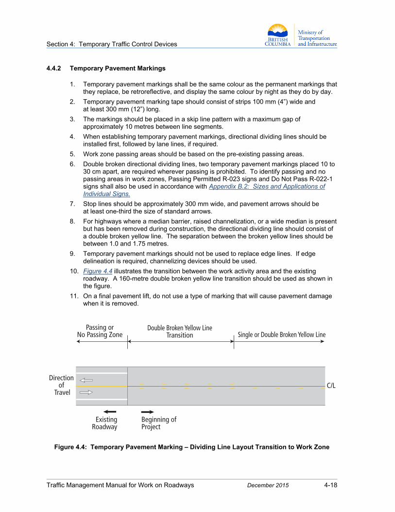
10. Figure 4.4 illustrates the transition between the work activity area and the existing roadway. A 160-metre double broken yellow line transition should be used as shown in the figure.
11. On a final pavement lift, do not use a type of marking that will cause pavement damage when it is removed.
Figure 4.4: Temporary Pavement Marking – Dividing Line Layout Transition to Work Zone
Direction of
Travel
Passing orNo Passing Zone
Double Broken Yellow LineTransition Single or Double Broken Yellow Line
Beginning ofProject
ExistingRoadway
C/L

Section 4: Temporary Traffic Control Devices
Traffic Management Manual for Work on Roadways December 2015 4-19
Figure 4.5: Temporary Pavement Markings – Directional Dividing Lane Layout at Intersections
A B
C
E
D
1/3 the size ofregular arrows
300 mm
C/L
C/L
LEGENDA Line Width
B Minimum Separation BetweenStripes for Double Broken Lines
C Minimum Stripe Length
D Gap Between Stripes (approximate)
E Stripe Offset from Centreline orPavement Joint (approximate)
Temporary Directional Dividing Line Layout
Condition A B* C D E (mm) (mm) (mm) (m) (mm)
Bondingagent used 100 600 300 10 300at C/L Joint
No bondingagent used or 100 100 300 10 50limited space
NOTES:* Use 1000 to 1750 mm separation
between double broken lines where median barrier, raised channeliza-tion, or a wide median was present but removed for construction.
Passing and no passing areas should be identified with signage using the guidelines established in this Manual and the Ministry’s Manual of Standard Traffic Signs and Pavement Markings.
This drawing illustrates the general layout of temporary directional dividing lines.

Section 4: Temporary Traffic Control Devices
Traffic Management Manual for Work on Roadways December 2015 4-20
4.4.3 Temporary Overlay Markers (TOMs) Temporary overlay markers are used as a standalone temporary pavement marking or as a supplement to other temporary pavement marking types. They are installed for both directional dividing lines and lane lines. TOMs are the only practical marking type for seal coating work and milled pavement
These devices are beneficial through changes in horizontal or vertical alignment, in areas where speeds and/or volumes are high, and where adverse weather conditions (such as fog or rain) might reasonably be expected in hours of darkness.
Figure 4.6: Temporary Overlay Markers (TOMs)
As a supplemental device, TOMs should be installed at a frequency of at least every third temporary marking, with the raised face perpendicular to traffic. TOMs should be installed frequently enough that at least four successive markers are visible in the direction of travel.
Section 4: Temporary Traffic Control Devices
Traffic Management Manual for Work on Roadways December 2015 4-21
4.5 Channelizing Devices
Channelizing devices are used to guide and direct road users through a work zone and around or away from hazards.
Channelizing devices include barriers, barricades, temporary lane separators, traffic cones, tubular markers, barrels/drums, vertical panels, and longitudinal channelizing barricades. Because they may be struck by errant vehicles, these devices are made crash-worthy using the NCHRP 350 testing regime for temporary devices.
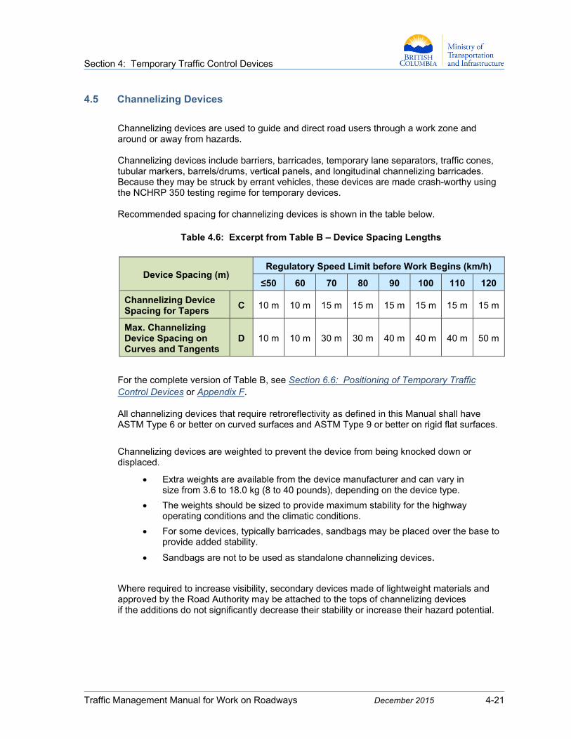
Recommended spacing for channelizing devices is shown in the table below.
Table 4.6: Excerpt from Table B – Device Spacing Lengths
Device Spacing (m) Regulatory Speed Limit before Work Begins (km/h)
≤50 60 70 80 90 100 110 120
Channelizing Device Spacing for Tapers
C 10 m 10 m 15 m 15 m 15 m 15 m 15 m 15 m
Max. Channelizing Device Spacing on Curves and Tangents
D 10 m 10 m 30 m 30 m 40 m 40 m 40 m 50 m
For the complete version of Table B, see Section 6.6: Positioning of Temporary Traffic Control Devices or Appendix F.
All channelizing devices that require retroreflectivity as defined in this Manual shall have ASTM Type 6 or better on curved surfaces and ASTM Type 9 or better on rigid flat surfaces.
Channelizing devices are weighted to prevent the device from being knocked down or displaced.
Extra weights are available from the device manufacturer and can vary in size from 3.6 to 18.0 kg (8 to 40 pounds), depending on the device type.
The weights should be sized to provide maximum stability for the highway operating conditions and the climatic conditions.
For some devices, typically barricades, sandbags may be placed over the base to provide added stability.
Sandbags are not to be used as standalone channelizing devices.
Where required to increase visibility, secondary devices made of lightweight materials and approved by the Road Authority may be attached to the tops of channelizing devices if the additions do not significantly decrease their stability or increase their hazard potential.

Section 4: Temporary Traffic Control Devices
Traffic Management Manual for Work on Roadways December 2015 4-22
Figure 4.7: Channelizing Devices
30 cm Min.(12 inches)
3 reflective Orange bands2 reflective White bands
Flexible Drum
100 cm Tubular Marker Vertical Panelwith Stand
Low Speed Roadway ≤ 60 km/hr
Wet PaintOperations
90 cm (35”)Minimum
45 cm Cone 70-90 cm Cone15 cm Cone
Type 2 Barricade Type 3 BarricadeType 1 Barricade
45 cm(18”)
70-90 cm(36”)
maximum
Optional2nd
WhiteBand
100 mm (4”)
75-100 mm (4”)
150 mm (6”)
50-75 mm (3”)
100 mm (4”)
75-100 mm (4”)
150 mm (6”)
150 mm (6”)
60 cm Min.(24”)
200-300 mm
(8”)
60 cm Min.(24”)
1.2 m Min. (47”)
90 cmMin.(35”)
90 cmMin.(35”)
1.5 mMin.(59”)
600 mmmin.
(24”min.)
300 mmmax.
150 mmand 45º
300 mmWhiteReflective
Bands
100 cm(40”)
minimum
50 mm (2”)100 mm (4”)
100 mm (4”)
150 mm (6”)

Section 4: Temporary Traffic Control Devices
Traffic Management Manual for Work on Roadways December 2015 4-23
4.5.1 Cones Cones are lightweight, flexible, channelization devices, and should be made of material that can be struck without causing damage. They are easy to install and remove, and can be nested for storage and transportation. Weighted bases may be used to increase the stability of the cone. Due to the light weight, cones should be checked frequently for correct positioning. Cones are used primarily for daylight operations. If they are used at night, they shall have retroreflective bands. The upper retroreflective band should be 15 cm (6”) wide and located 8 to 10 cm (3” to 4”) from the top of the cone. For 90 cm cones, a second band 10 cm (4”) wide should be located approximately 5 cm (2”) below the first.
Figure 4.8: Cones
15 cm (6”) cones are used only to protect freshly applied pavement markings
during the drying process.
45 cm (18”) cones are the type most commonly used for traffic control, usually to delineate work activity areas and specific hazards that are in or adjacent to the travel path.
They may also be used to form the shorter tapers required for shoulder work or for travel lanes when traffic is controlled by Traffic Control Persons, portable lane control signals, or temporary traffic signals.
If the speed limit is < 60 km/h and traffic is free flow, 45 cm cones may be used for full lane closure tapers. In these lower speed zones, smaller 30 cm (12”) cones may be substituted for 45 cm cones in any application at the discretion of the Road Authority.
70 cm (28”) cones may be substituted for 45 cm cones in any application where the additional height would be advantageous. They may be used on high-speed roadways, or at night.
90 cm (36”) cones may be a substitute for tubular markers.
Lane Closure Tapers60 km/h or less
May be substitutedfor 45 cm
Speed Limit 70 km/hor greater (May be
substituted for 45 cm cone)
for roadmarking
only
WhiteReflectorized
Band
All FluorescentRed-Orange
100 mm(4”)
100 mm (4”)
75-100 mm(3-4”)
150 mm (6”)
150 mm (6”)
50-75 mm (2”)
150 mm(6”)
150 mm (6”)
70 cm(28”)
15 cm(6”)
45 cm(18”)
90 cm(36”)
minimum
WhiteReflectorized
Band

Section 4: Temporary Traffic Control Devices
Traffic Management Manual for Work on Roadways December 2015 4-24
4.5.2 Tubular Markers (Tubes) Tubular markers (tubes) are lightweight channelizing devices which are easy to install and remove. They are particularly good for delineating travel lanes. They are predominantly orange, and made of a material that can be struck without causing damage to the impacting vehicle. They include two retroreflective bands. Tubes should be at least 100 cm (40”) high and 10 cm (4”) in diameter. Other dimensions may be used for specific applications only if approved by the Road Authority.
Tubular markers may be used to divide travel lanes and delineate the edge of a pavement drop-off if space limitations prevent the use of larger devices.
Figure 4.9: Tubular Markers
Tubes should not be a substitute for drums or barricades to mark hazards or to close roadways, unless space restrictions prevent the use of more visible devices. Tubes are stabilized by using weighted bases or weights like sandbag rings that can be dropped over them and onto the base. The weighted base should weigh at least 5.5 kg (12 pounds). Additional weights may be required in high-speed applications and where road conditions dictate. Tubular markers used on Provincial highways shall have two white retroreflective bands at least 100 mm (4”) wide near the top of the post. The first band is placed approximately 50 mm (2”) down from the top edge, and the gap between the bands is approximately 150 mm (6”). Tubes may replace 45 cm and 70 cm cones in any of their applications if reasonable stability is assured.
WhiteReflective
Bands
Minimum weight ofbase should be 5.5 kg (12 lbs)
100 cm(40”)
minimum
50 mm (2”)
100 mm (4”)
100 mm (4”)
150 mm (6”)
Section 4: Temporary Traffic Control Devices
Traffic Management Manual for Work on Roadways December 2015 4-25
4.5.3 Drums/Barrels
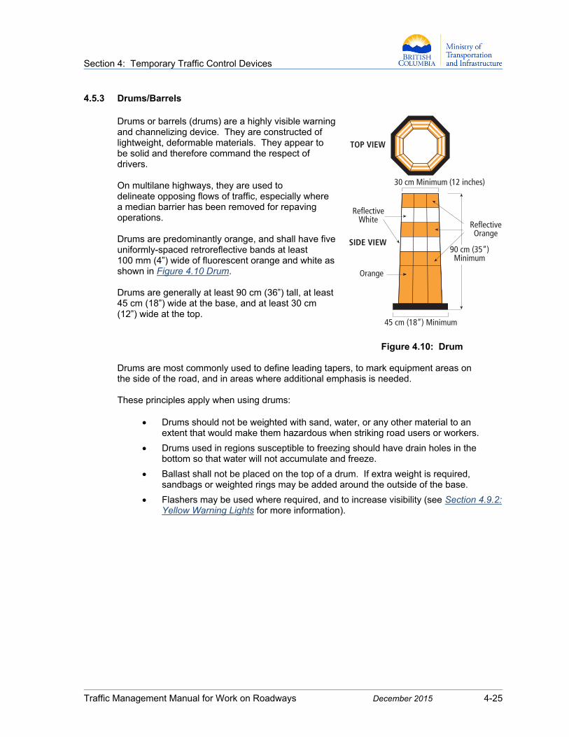
Drums or barrels (drums) are a highly visible warning and channelizing device. They are constructed of lightweight, deformable materials. They appear to be solid and therefore command the respect of drivers. On multilane highways, they are used to delineate opposing flows of traffic, especially where a median barrier has been removed for repaving operations. Drums are predominantly orange, and shall have five uniformly-spaced retroreflective bands at least 100 mm (4”) wide of fluorescent orange and white as shown in Figure 4.10 Drum. Drums are generally at least 90 cm (36”) tall, at least 45 cm (18”) wide at the base, and at least 30 cm (12”) wide at the top.
Figure 4.10: Drum
Drums are most commonly used to define leading tapers, to mark equipment areas on the side of the road, and in areas where additional emphasis is needed. These principles apply when using drums:
Drums should not be weighted with sand, water, or any other material to an extent that would make them hazardous when striking road users or workers.
Drums used in regions susceptible to freezing should have drain holes in the bottom so that water will not accumulate and freeze.
Ballast shall not be placed on the top of a drum. If extra weight is required, sandbags or weighted rings may be added around the outside of the base.
Flashers may be used where required, and to increase visibility (see Section 4.9.2: Yellow Warning Lights for more information).
TOP VIEW
SIDE VIEW
30 cm Minimum (12 inches)
90 cm (35”)Minimum
45 cm (18”) Minimum
Orange
ReflectiveWhite
ReflectiveOrange
Section 4: Temporary Traffic Control Devices
Traffic Management Manual for Work on Roadways December 2015 4-26
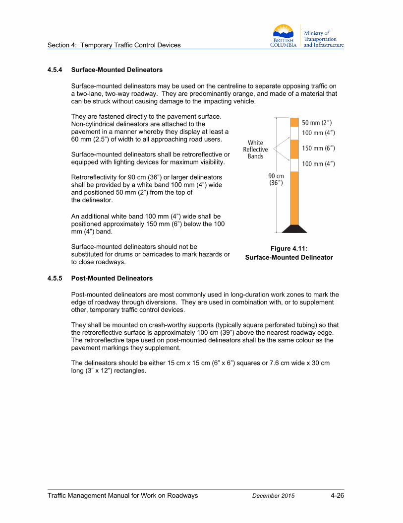
4.5.4 Surface-Mounted Delineators Surface-mounted delineators may be used on the centreline to separate opposing traffic on a two-lane, two-way roadway. They are predominantly orange, and made of a material that can be struck without causing damage to the impacting vehicle. They are fastened directly to the pavement surface. Non-cylindrical delineators are attached to the pavement in a manner whereby they display at least a 60 mm (2.5”) of width to all approaching road users. Surface-mounted delineators shall be retroreflective or equipped with lighting devices for maximum visibility. Retroreflectivity for 90 cm (36”) or larger delineators shall be provided by a white band 100 mm (4”) wide and positioned 50 mm (2”) from the top of the delineator. An additional white band 100 mm (4”) wide shall be positioned approximately 150 mm (6”) below the 100 mm (4”) band. Surface-mounted delineators should not be substituted for drums or barricades to mark hazards or to close roadways.
Figure 4.11: Surface-Mounted Delineator
4.5.5 Post-Mounted Delineators
Post-mounted delineators are most commonly used in long-duration work zones to mark the edge of roadway through diversions. They are used in combination with, or to supplement other, temporary traffic control devices.
They shall be mounted on crash-worthy supports (typically square perforated tubing) so that the retroreflective surface is approximately 100 cm (39”) above the nearest roadway edge. The retroreflective tape used on post-mounted delineators shall be the same colour as the pavement markings they supplement.
The delineators should be either 15 cm x 15 cm (6” x 6”) squares or 7.6 cm wide x 30 cm long (3” x 12”) rectangles.
90 cm(36”)
50 mm (2”)
100 mm (4”)
100 mm (4”)
150 mm (6”)White
ReflectiveBands

Section 4: Temporary Traffic Control Devices
Traffic Management Manual for Work on Roadways December 2015 4-27
4.5.6 Vertical Panels
Vertical panels have a retroreflective, striped face that is at least 300 mm (12”) wide and 600 mm (24”) high. They may be surface or temporary curb mounted. They shall have alternating, diagonal fluorescent orange and white retroreflective stripes sloping downward at a 45-degree angle in the direction that vehicular traffic is to pass. Where space is limited, vertical panels may be used to channelize vehicular traffic or to divide opposing lanes. When used as channelizing devices, vertical panels shall be secured such that the side facing traffic is at least 300 mm (12”) wide and 600 mm (24”) high.
Figure 4.12: Vertical Panel
Section 4: Temporary Traffic Control Devices
Traffic Management Manual for Work on Roadways December 2015 4-28
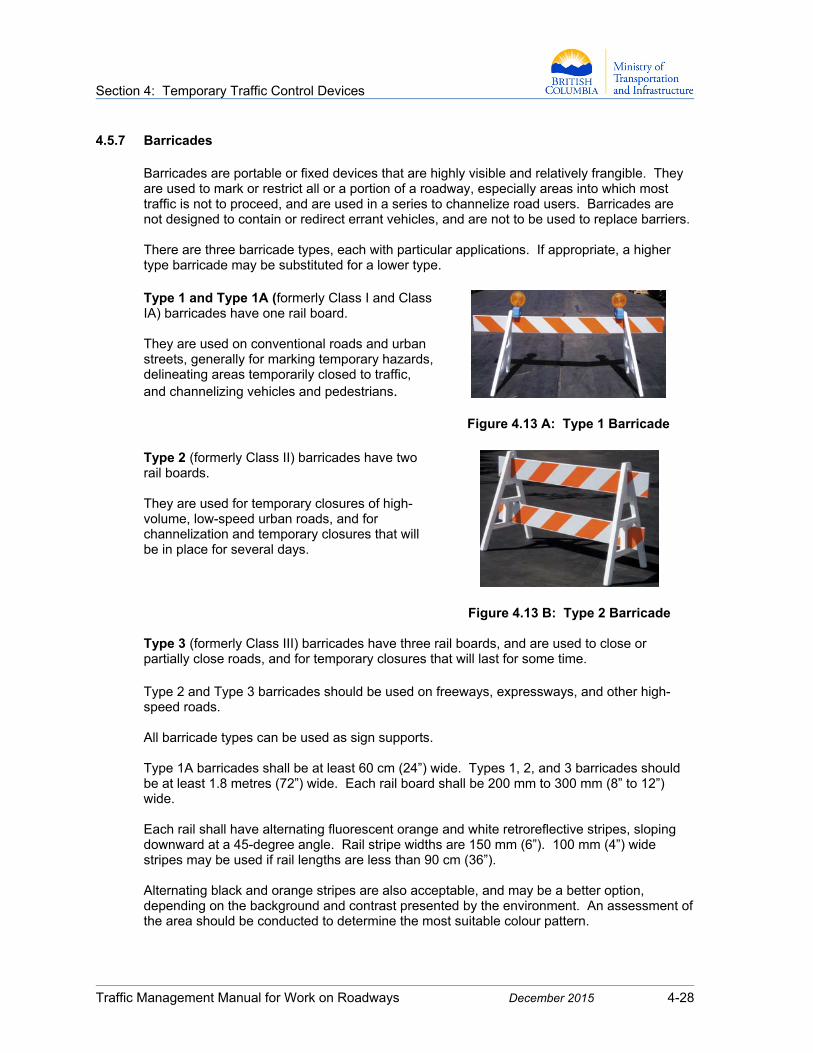
4.5.7 Barricades Barricades are portable or fixed devices that are highly visible and relatively frangible. They are used to mark or restrict all or a portion of a roadway, especially areas into which most traffic is not to proceed, and are used in a series to channelize road users. Barricades are not designed to contain or redirect errant vehicles, and are not to be used to replace barriers. There are three barricade types, each with particular applications. If appropriate, a higher type barricade may be substituted for a lower type. Type 1 and Type 1A (formerly Class I and Class IA) barricades have one rail board.
They are used on conventional roads and urban streets, generally for marking temporary hazards, delineating areas temporarily closed to traffic, and channelizing vehicles and pedestrians.
Figure 4.13 A: Type 1 Barricade
Type 2 (formerly Class II) barricades have two rail boards.
They are used for temporary closures of high-volume, low-speed urban roads, and for channelization and temporary closures that will be in place for several days.
Figure 4.13 B: Type 2 Barricade Type 3 (formerly Class III) barricades have three rail boards, and are used to close or partially close roads, and for temporary closures that will last for some time.
Type 2 and Type 3 barricades should be used on freeways, expressways, and other high-speed roads. All barricade types can be used as sign supports. Type 1A barricades shall be at least 60 cm (24”) wide. Types 1, 2, and 3 barricades should be at least 1.8 metres (72”) wide. Each rail board shall be 200 mm to 300 mm (8” to 12”) wide.
Each rail shall have alternating fluorescent orange and white retroreflective stripes, sloping downward at a 45-degree angle. Rail stripe widths are 150 mm (6”). 100 mm (4”) wide stripes may be used if rail lengths are less than 90 cm (36”).
Alternating black and orange stripes are also acceptable, and may be a better option, depending on the background and contrast presented by the environment. An assessment of the area should be conducted to determine the most suitable colour pattern.

Section 4: Temporary Traffic Control Devices
Traffic Management Manual for Work on Roadways December 2015 4-29
Figure 4.14: Type 1 Black and Orange Barricade
Follow these guidelines when using barricades:
1. Where barricades extend entirely across a roadway, the stripes should slope downward in the direction toward which road users are to pass. Where both right and left turns are provided, the stripes should slope downward in both directions from the center of the barricade or barricades. Where no turns are intended, the stripes should slope downward toward the center of the barricade or barricades.
2. Barricades used on expressways, freeways, and other high-speed roadways shall have at least 1,700 square centimeters (270 square inches) of retroreflective area facing traffic. Where traffic may approach a barricade from either side, the barricade should be retroreflective on both sides, or two barricades should be positioned back-to-back.
3. Road Closed R-012, Local Traffic Only R-012-T, and Detour C-005-LR signs may be attached to the highest barricade rail if required.
4. When a highway is closed but access is still allowed for local road users, barricades are not normally extended completely across the roadway.
5. Flashers may be used on top of the barricade to increase visibility (see Section 4.9.2: Yellow Warning Lights).
6. The stability of portable barricades can be enhanced by using sandbags, provided that they are placed on or close to the barricade bases. Weight should not be placed on the top of any rail. Non-deformable objects like rocks or concrete should not be used to weight the barricade.
Section 4: Temporary Traffic Control Devices
Traffic Management Manual for Work on Roadways December 2015 4-30
4.5.8 Temporary Roadside/Median Barrier In temporary traffic control, barrier and barricades are two different and distinct devices.
Barricades (see Section 4.5.7: Barricades) are lightweight devices that are relatively forgiving of errant vehicles. They are normally placed at or nearly at right angles to approaching traffic to provide visual identification of hazardous locations and to delineate travel paths.
Barrier is designed to contain and redirect errant vehicles. It is a solid, continuous installations designed to deflect errant vehicles at a small angle, thereby preventing them from entering a closed or hazardous area. It is normally placed parallel to or nearly parallel to approaching traffic.
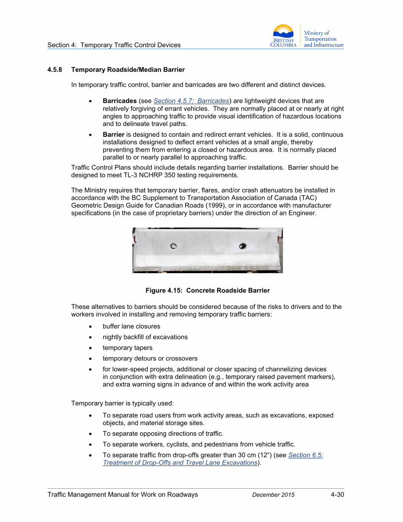
Traffic Control Plans should include details regarding barrier installations. Barrier should be designed to meet TL-3 NCHRP 350 testing requirements. The Ministry requires that temporary barrier, flares, and/or crash attenuators be installed in accordance with the BC Supplement to Transportation Association of Canada (TAC) Geometric Design Guide for Canadian Roads (1999), or in accordance with manufacturer specifications (in the case of proprietary barriers) under the direction of an Engineer.
Figure 4.15: Concrete Roadside Barrier
These alternatives to barriers should be considered because of the risks to drivers and to the workers involved in installing and removing temporary traffic barriers:
buffer lane closures
nightly backfill of excavations
temporary tapers
temporary detours or crossovers
for lower-speed projects, additional or closer spacing of channelizing devices in conjunction with extra delineation (e.g., temporary raised pavement markers), and extra warning signs in advance of and within the work activity area
Temporary barrier is typically used:
To separate road users from work activity areas, such as excavations, exposed objects, and material storage sites.
To separate opposing directions of traffic.
To separate workers, cyclists, and pedestrians from vehicle traffic.
To separate traffic from drop-offs greater than 30 cm (12”) (see Section 6.5: Treatment of Drop-Offs and Travel Lane Excavations).
Section 4: Temporary Traffic Control Devices
Traffic Management Manual for Work on Roadways December 2015 4-31
Follow these guidelines when using barrier:
Barriers used as channelizing devices should be equipped with reflectors and/or Type A, B, or C yellow lights (see Section 4.9.2: Yellow Warning Lights).
If sufficient room is available, a solid lane edge line may be installed to indicate shy distance.
When barrier is used for lane closures, they shall be preceded by devices placed for a standard lane closure taper.
When barrier restricts roadway width, enough width should be provided for the largest anticipated vehicle.
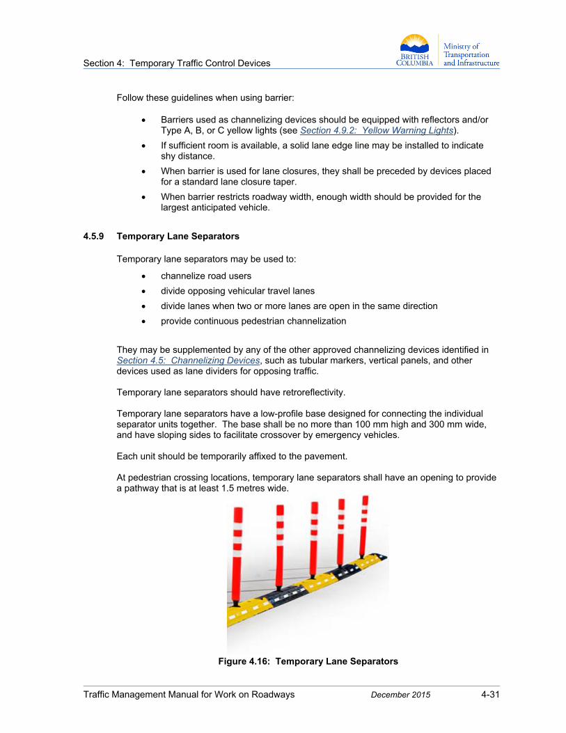
4.5.9 Temporary Lane Separators Temporary lane separators may be used to:
channelize road users
divide opposing vehicular travel lanes
divide lanes when two or more lanes are open in the same direction
provide continuous pedestrian channelization
They may be supplemented by any of the other approved channelizing devices identified in Section 4.5: Channelizing Devices, such as tubular markers, vertical panels, and other devices used as lane dividers for opposing traffic. Temporary lane separators should have retroreflectivity. Temporary lane separators have a low-profile base designed for connecting the individual separator units together. The base shall be no more than 100 mm high and 300 mm wide, and have sloping sides to facilitate crossover by emergency vehicles. Each unit should be temporarily affixed to the pavement. At pedestrian crossing locations, temporary lane separators shall have an opening to provide a pathway that is at least 1.5 metres wide.
Figure 4.16: Temporary Lane Separators
Section 4: Temporary Traffic Control Devices
Traffic Management Manual for Work on Roadways December 2015 4-32
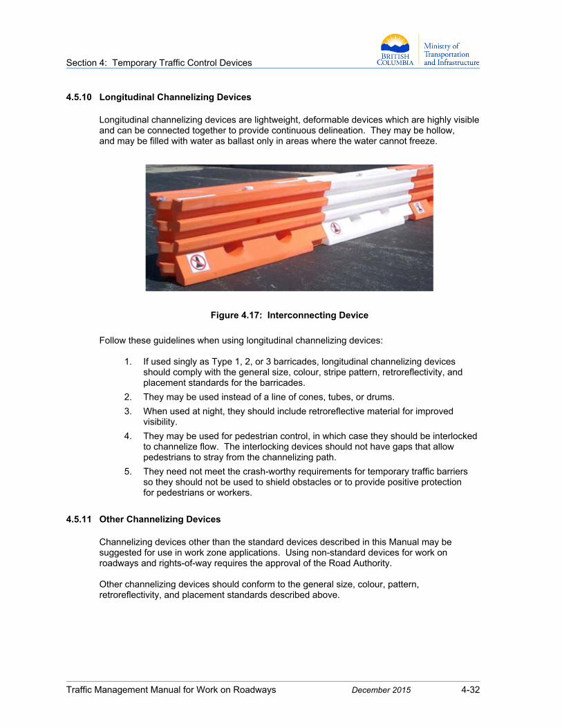
4.5.10 Longitudinal Channelizing Devices Longitudinal channelizing devices are lightweight, deformable devices which are highly visible and can be connected together to provide continuous delineation. They may be hollow, and may be filled with water as ballast only in areas where the water cannot freeze.
Figure 4.17: Interconnecting Device
Follow these guidelines when using longitudinal channelizing devices:
1. If used singly as Type 1, 2, or 3 barricades, longitudinal channelizing devices should comply with the general size, colour, stripe pattern, retroreflectivity, and placement standards for the barricades.
2. They may be used instead of a line of cones, tubes, or drums.
3. When used at night, they should include retroreflective material for improved visibility.
4. They may be used for pedestrian control, in which case they should be interlocked to channelize flow. The interlocking devices should not have gaps that allow pedestrians to stray from the channelizing path.
5. They need not meet the crash-worthy requirements for temporary traffic barriers so they should not be used to shield obstacles or to provide positive protection for pedestrians or workers.
4.5.11 Other Channelizing Devices
Channelizing devices other than the standard devices described in this Manual may be suggested for use in work zone applications. Using non-standard devices for work on roadways and rights-of-way requires the approval of the Road Authority. Other channelizing devices should conform to the general size, colour, pattern, retroreflectivity, and placement standards described above.

Section 4: Temporary Traffic Control Devices
Traffic Management Manual for Work on Roadways December 2015 4-33
4.6 Flashing Arrow Boards (FABs)
Flashing arrow boards (FABs) are signs with a matrix of elements that are capable of either flashing or sequential displays. They are very effective both day and night, providing additional warning and directional information that assists with controlling and merging road users through or around a work zone. Their main purpose on multilane roadways is to direct traffic from a closed lane into another available lane with appropriate arrow indications. They can be used for either static or moving operations. Normally only one arrow head is displayed at a time. Without directional indication, FABs can be used in place of, or in addition to, 4-way flashers and 360-degree warning lights to create a more visible warning that work is in progress. They can be mounted on trucks or trailers for both stationary and moving operations. FABs shall not be used in directional display mode when:
A lane closure is not required.
All the work is on or outside the shoulder, and there is no need to close the adjacent travel lane.
A Traffic Control Person is controlling traffic on what is normally a two-lane, two-way roadway.
4.6.1 FAB Specifications
1. Types
Flashing arrow boards are differentiated by size, where:
Type A arrow boards are for low-speed urban streets.
Type B arrow boards are for intermediate-speed facilities and maintenance or mobile operations on high-speed roadways.
Type C arrow boards are for projects on high-speed, high-volume highways.
Type D arrow boards are for use on vehicles authorized by the Road Authority.
Type A, B, and C arrow boards should have a solid rectangular appearance, whereas Type D arrow boards conform to the shape of the arrow. All arrow board faces should be finished in non-reflective black.
Figure 4.18: Type D Arrow Board
Section 4: Temporary Traffic Control Devices
Traffic Management Manual for Work on Roadways December 2015 4-34
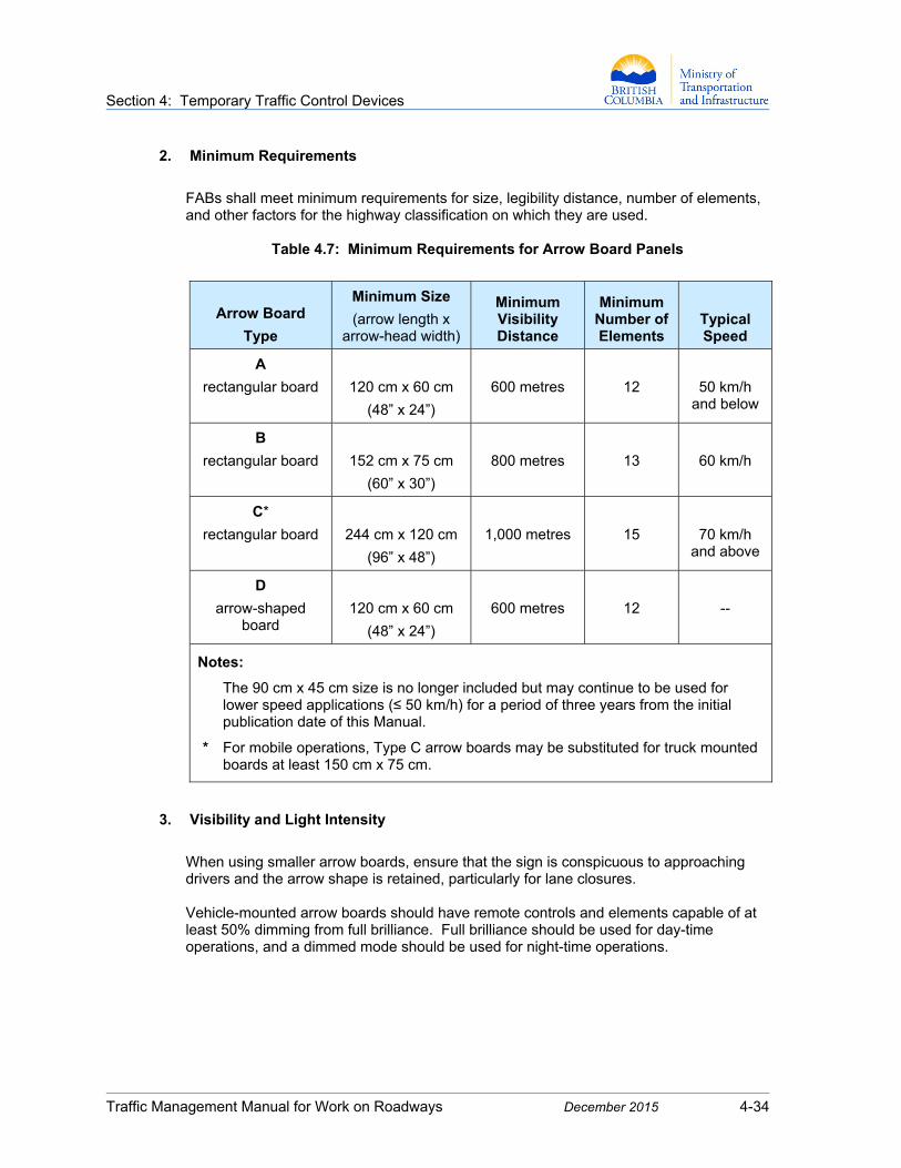
2. Minimum Requirements
FABs shall meet minimum requirements for size, legibility distance, number of elements, and other factors for the highway classification on which they are used.
Table 4.7: Minimum Requirements for Arrow Board Panels
Arrow Board
Type
Minimum Size
(arrow length x arrow-head width)
Minimum Visibility Distance
Minimum Number of Elements
Typical Speed
A
rectangular board
120 cm x 60 cm
(48” x 24”)
600 metres
12
50 km/h and below
B
rectangular board
152 cm x 75 cm
(60” x 30”)
800 metres
13
60 km/h
C*
rectangular board
244 cm x 120 cm
(96” x 48”)
1,000 metres
15
70 km/h and above
D
arrow-shaped board
120 cm x 60 cm
(48” x 24”)
600 metres
12
--
Notes:
The 90 cm x 45 cm size is no longer included but may continue to be used for lower speed applications (≤ 50 km/h) for a period of three years from the initial publication date of this Manual.
* For mobile operations, Type C arrow boards may be substituted for truck mounted boards at least 150 cm x 75 cm.
3. Visibility and Light Intensity
When using smaller arrow boards, ensure that the sign is conspicuous to approaching drivers and the arrow shape is retained, particularly for lane closures. Vehicle-mounted arrow boards should have remote controls and elements capable of at least 50% dimming from full brilliance. Full brilliance should be used for day-time operations, and a dimmed mode should be used for night-time operations.
Section 4: Temporary Traffic Control Devices
Traffic Management Manual for Work on Roadways December 2015 4-35
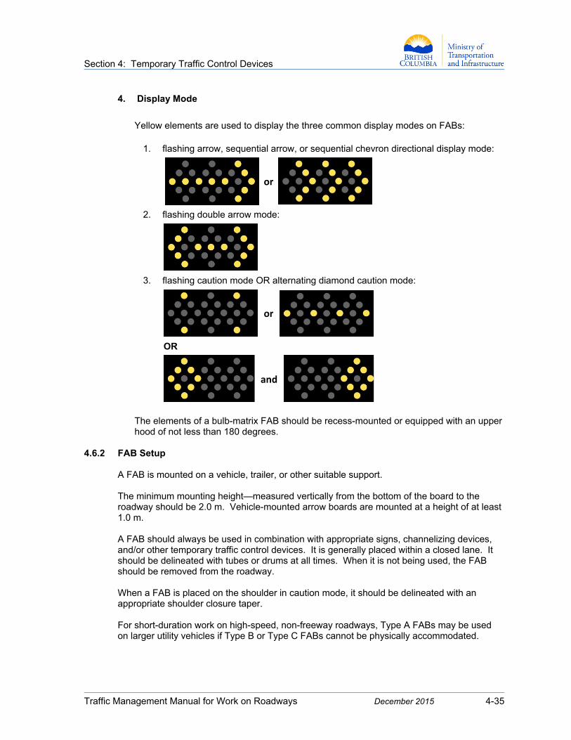
4. Display Mode
Yellow elements are used to display the three common display modes on FABs:
1. flashing arrow, sequential arrow, or sequential chevron directional display mode:
or
2. flashing double arrow mode:
3. flashing caution mode OR alternating diamond caution mode:
or
OR
and
The elements of a bulb-matrix FAB should be recess-mounted or equipped with an upper hood of not less than 180 degrees.
4.6.2 FAB Setup
A FAB is mounted on a vehicle, trailer, or other suitable support. The minimum mounting height—measured vertically from the bottom of the board to the roadway should be 2.0 m. Vehicle-mounted arrow boards are mounted at a height of at least 1.0 m. A FAB should always be used in combination with appropriate signs, channelizing devices, and/or other temporary traffic control devices. It is generally placed within a closed lane. It should be delineated with tubes or drums at all times. When it is not being used, the FAB should be removed from the roadway. When a FAB is placed on the shoulder in caution mode, it should be delineated with an appropriate shoulder closure taper. For short-duration work on high-speed, non-freeway roadways, Type A FABs may be used on larger utility vehicles if Type B or Type C FABs cannot be physically accommodated.

Section 4: Temporary Traffic Control Devices
Traffic Management Manual for Work on Roadways December 2015 4-36
Driver sight lines should be assessed when placing FABs to ensure maximum visibility without creating a hazard. Considering the curvature of the roadway, place the FAB in a position where there are no visual obstructions between it and the driver. FABs should be set up as follows:
1. For a lane closure that uses a stationary FAB (trailer-mounted), the arrow board should be positioned within the closed lane, near the end of the merging taper.
2. For a lane closure that uses a mobile FAB (truck-mounted), the arrow board should be positioned to provide enough separation from the work operation to allow approaching drivers to react appropriately.
3. For multiple lane closures, a separate arrow board shall be used for each closed lane.
4.6.3 FAB Operation
1. Determine the appropriate FAB display option based on the traffic control layout.
2. For flashing and sequencing arrow boards, the minimum element “on time” shall be 50% for the flashing mode, with equal intervals of 25% for each sequential phase. The flash rate should be between 25 and 40 flashes per minute.
Sequencing arrow panels have several arrowheads that flash in a series, directing traffic to the right or left.
3. An arrow board in arrow or chevron mode can be used only for stationary or moving lane closures on multilane roadways.
4. An arrow board may be used in caution mode in situations that include, but are not limited to:
roadside work on or near the shoulder
temporarily closing one lane on a two-lane, two-way roadway
5. A Dynamic Message Sign (DMS) may be used to simulate an arrow board display.
4.6.4 Arrow Sticks
Arrow sticks are vehicle-mounted sequential flashing devices used to supplement other temporary traffic control devices. They shall not be used as a replacement for FABs. An arrow stick can be used to indicate “move/merge…right/left.” They can also be used as a flashing bar to indicate that caution is required.
Figure 4.19: Arrow Sticks
Section 4: Temporary Traffic Control Devices
Traffic Management Manual for Work on Roadways December 2015 4-37
4.7 Automated Flagger Assistance Devices (AFADs)
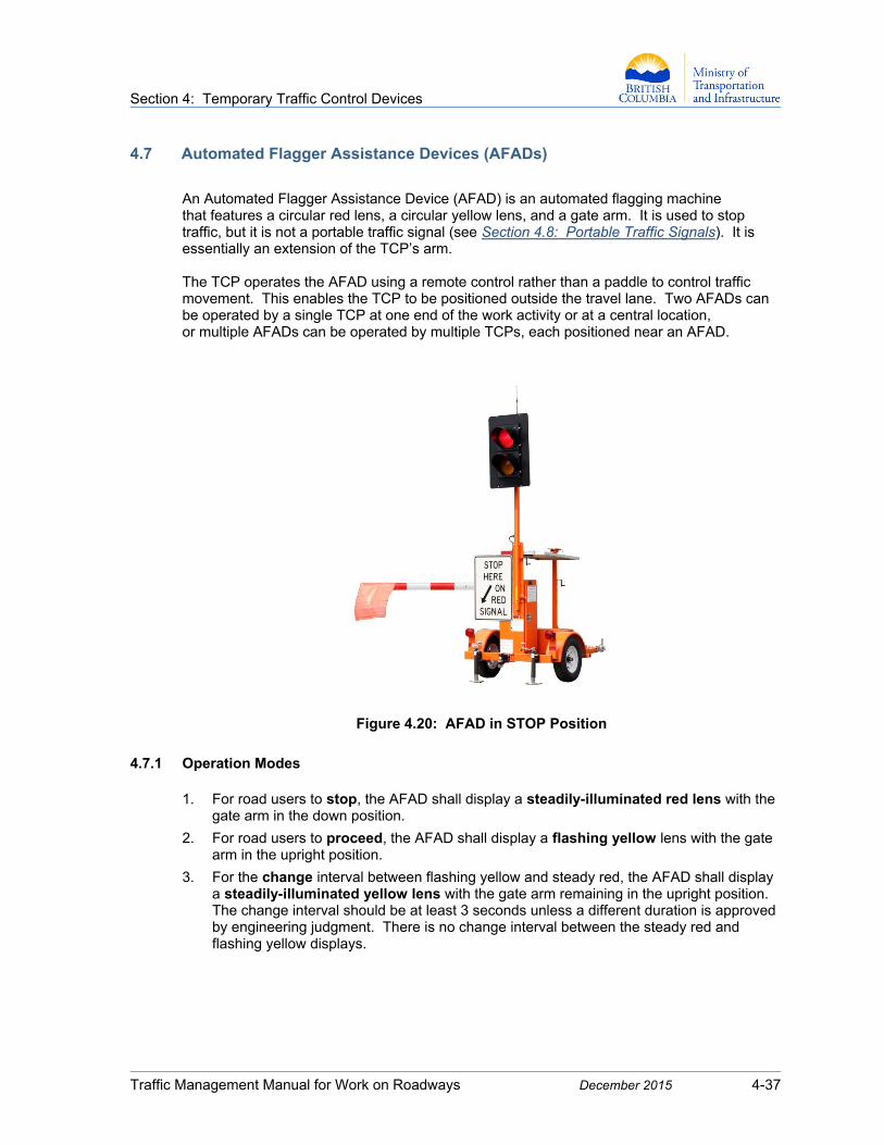
An Automated Flagger Assistance Device (AFAD) is an automated flagging machine that features a circular red lens, a circular yellow lens, and a gate arm. It is used to stop traffic, but it is not a portable traffic signal (see Section 4.8: Portable Traffic Signals). It is essentially an extension of the TCP’s arm. The TCP operates the AFAD using a remote control rather than a paddle to control traffic movement. This enables the TCP to be positioned outside the travel lane. Two AFADs can be operated by a single TCP at one end of the work activity or at a central location, or multiple AFADs can be operated by multiple TCPs, each positioned near an AFAD.
Figure 4.20: AFAD in STOP Position
4.7.1 Operation Modes 1. For road users to stop, the AFAD shall display a steadily-illuminated red lens with the
gate arm in the down position.
2. For road users to proceed, the AFAD shall display a flashing yellow lens with the gate arm in the upright position.
3. For the change interval between flashing yellow and steady red, the AFAD shall display a steadily-illuminated yellow lens with the gate arm remaining in the upright position. The change interval should be at least 3 seconds unless a different duration is approved by engineering judgment. There is no change interval between the steady red and flashing yellow displays.
Section 4: Temporary Traffic Control Devices
Traffic Management Manual for Work on Roadways December 2015 4-38
4.7.2 Deployment Guidelines 1. AFADs may be used only on two-lane, two-way roadways and on multilane roadways
that have been reduced to one lane.
2. When used at night, the AFAD station shall be illuminated with overhead lighting.
3. The speed limit where AFADs are used shall be ≤ 70 km/h. High-speed roadways require a speed reduction.
4. An AFAD is not a traffic control signal, and it cannot be used to replace or substitute for a continuously-operating temporary traffic control signal.
5. An AFAD can be operated only by a TCP who has been trained to operate it.
6. A TCP operating an AFAD shall not leave it unattended at any time while it is in use.
4.7.3 Equipment Requirements
1. The AFAD shall have two 300 mm diameter signal lenses—i.e., a lens that displays solid
red above a lens that displays flashing yellow. The flashing yellow lens shall also have solid yellow capability for change intervals.
2. The AFAD shall have a conflict monitor that prevents simultaneous illumination of the red and yellow lenses on the same device.
3. The AFAD shall have a gate arm with the following properties:
A fluorescent orange or red flag shall be installed at the end of the gate arm when the AFAD is in use.
The gate arm shall be at least 3.05 m (10 feet) long, including the flag, and shall have a vertical aspect of at least 100 mm (4 in).
The gate arm shall lower and remain lowered on a red signal.
The gate arm shall rise to an upright position on a flashing yellow signal.
The gate arm shall have retroreflectivity on both sides with alternating fluorescent red and white bands. The bands shall be 200 mm (8”) long measured horizontally.
4. A black-on-white STOP HERE ON RED or STOP HERE ON RED SIGNAL sign shall be installed on the right side of the approach at the point where drivers are expected to stop. This sign is typically provided with the AFAD, and may be installed on it.
Section 4: Temporary Traffic Control Devices
Traffic Management Manual for Work on Roadways December 2015 4-39
4.7.4 AFAD Placement and Operating Options AFADs are placed either at each end of the work activity area or at one end of the work activity area with a TCP at the opposite end. Signing and AFAD placement are shown in Figure 7.9: Lane Closure with AFADs. The preferred operating option is to have a TCP controller for each AFAD. Assigning a TCP to each device becomes more critical on high-volume roadways and in more complex work zones where construction traffic may be entering and exiting frequently. For simpler, lower-volume situations where there are good sight lines, a single TCP may control up to two AFADs:
1. Two-TCP Operation (Typical):
One TCP operates each AFAD at either end of the work activity area; or
One TCP operates an AFAD at one end of the work activity area and the second TCP controls traffic with a paddle at the other end.
2. Single-TCP Operation:
One TCP positioned in a central location simultaneously operates two AFADs that are positioned at either end of the work activity area; or
One TCP operates a single AFAD that is positioned at one end of the work activity area while also controlling traffic with a paddle at the opposite end.
In a single-TCP operation, all of these conditions shall be met:
The TCP has an unobstructed view of the AFAD(s).
The TCP has unobstructed views of approaching traffic in both directions.
The average daily traffic volume on the roadway is 6,000 vehicles or less.
The maximum distance between traffic control stations (TCP or AFAD) is 250 m.
Conflicting displays that release traffic in both directions simultaneously should be prevented by establishing clear communication procedures for fail-safe operation before work commences.
A TCP shall not activate the flashing yellow display (proceed) until the last vehicle from the opposing queue has cleared the work activity area.

Section 4: Temporary Traffic Control Devices
Traffic Management Manual for Work on Roadways December 2015 4-40
4.8 Portable Traffic Signals
Acceptance by the Road Authority is required prior to using Portable Traffic Signals.
4.8.1 Deployment Guidelines
A portable traffic signal is a mobile traffic control system in which two signal heads are mounted on a self-contained trailer. Portable traffic signals can be used in specific circumstances to regulate single-lane alternating traffic during long-duration work—for example, on single-lane bridges and in rural construction environments. They may not be appropriate in mobile work zones and in work zones where there are several access and egress requirements for public and construction traffic. There are two categories of portable traffic signals:
1. Category 1 Portable Signal: A fixed-time signal used for short-duration work in low-speed environments (≤ 60 km/h) and where advance warning flashers are not required. A Traffic Engineer need not prepare the timing sheet for this signal.
2. Category 2 Portable Signal: An actuated signal or fixed-time signal used for long-duration work, and/or in high-speed environments (≥ 70 km/h), and/or where advance warning flashers are required. A Traffic Engineer shall prepare the timing sheet for this signal.
Figure 4.21: Portable Traffic Signal Mounted on Trailer
Section 4: Temporary Traffic Control Devices
Traffic Management Manual for Work on Roadways December 2015 4-41
Portable traffic signals are used primarily to provide bi-directional traffic control in longer-term work zones. Typically, a pair of signals is set up at the perimeter of a roadway construction site, and signal communication is provided via radio interface. Each signal unit shall have at least two signal heads for each approach and shall be positioned so that at least one signal head is overhead and one is side-mounted (see Figure 4.21: Portable Traffic Signal Mounted on Trailer). The signal heads should consist of three coloured displays with 300 mm (12”) lenses. See Figure 7.10 Lane Closure with Temporary Signals for details on site layout.
4.8.2 Operational Guidelines
The operation of a portable traffic signal should consider:
traffic volumes, including roadway and intersection capacity
vehicle speeds
work staging and operations
sight distance restrictions
affected side streets and driveways
nature of adjacent land uses (e.g., residential or commercial)
pedestrians, and the use of pedestrian signal displays and audible signals
signal phasing and timing requirements
full-time or part-time operation
actuated, fixed-time, or manual operation
advance warning flashers
power failures or other emergencies
The signal units should be powered by reliable power sources capable of operating the signals at all times unless traffic is controlled by Traffic Control Persons. The units may also be capable of communicating information remotely to traffic management personnel, such as errors or low battery levels. Portable traffic signals shall be documented in the Traffic Control Plan and implemented in accordance with the standards specified in this Manual. Records shall be kept that identify placement, signal timing, inspection, and maintenance. Drums should be placed on the approach side of the signals to provide notification and protection for road users, including cyclists. Portable traffic signals that are not in use should be covered or removed.
Section 4: Temporary Traffic Control Devices
Traffic Management Manual for Work on Roadways December 2015 4-42
Additional features to be included in a portable traffic signal system are:
manual override to hold signal in green
conflict monitor to ensure that the two signals in a pair cannot show green simultaneously
ability to revert to flashing red mode if a fault is detected (i.e., low battery, lamp defect, lost communication, etc.)
low-battery warning system, if applicable
vehicle detection
Advance warning flashers are required where one or more of the following conditions apply (see also the Ministry’s Electrical and Traffic Engineering Manual, Section 400):
visibility of the signal is obstructed because of vertical or horizontal alignment
grade approaching the signal requires more than normal braking effort
posted speed limit for the highway is ≥ 70 km/h
Road Authority has requested advance warning flashers
The Traffic Signal Ahead C-112 sign should be used in accordance with Appendix B: Standard Construction Signs.
Portable traffic signals should be inspected at least once a day for:
traffic operation (vehicle delay and throughput)
signal alignment
signal display failures
power supply
signs of vandalism
C-112
Traffic Signal Ahead
If Category 2 portable signals will be used on a project, the Traffic Management Plan shall include:
Portable Traffic Signal Timing Plan stamped by a Traffic Engineer.
Portable Traffic Signal Site Layout Plan indicating the location of the site, position of the signals relative to the project site, distance between stop bars, distance between stop bars and advance warning sign (if applicable), location of vehicle-detection system, devices used to protect the signals, and other relevant information.
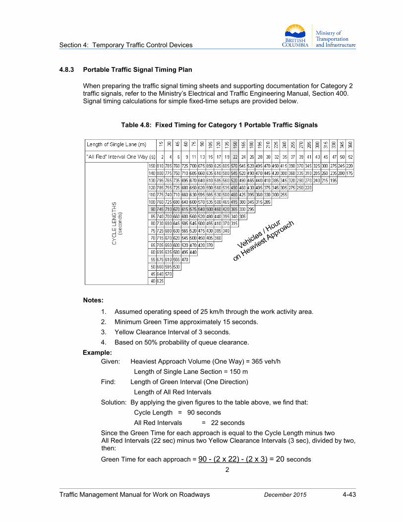
Section 4: Temporary Traffic Control Devices
Traffic Management Manual for Work on Roadways December 2015 4-43
4.8.3 Portable Traffic Signal Timing Plan When preparing the traffic signal timing sheets and supporting documentation for Category 2 traffic signals, refer to the Ministry’s Electrical and Traffic Engineering Manual, Section 400. Signal timing calculations for simple fixed-time setups are provided below.
Table 4.8: Fixed Timing for Category 1 Portable Traffic Signals
Notes:
1. Assumed operating speed of 25 km/h through the work activity area.
2. Minimum Green Time approximately 15 seconds.
3. Yellow Clearance Interval of 3 seconds.
4. Based on 50% probability of queue clearance.
Example: Given: Heaviest Approach Volume (One Way) = 365 veh/h
Length of Single Lane Section = 150 m
Find: Length of Green Interval (One Direction)
Length of All Red Intervals
Solution: By applying the given figures to the table above, we find that:
Cycle Length = 90 seconds
All Red Intervals = 22 seconds
Since the Green Time for each approach is equal to the Cycle Length minus two All Red Intervals (22 sec) minus two Yellow Clearance Intervals (3 sec), divided by two, then:
Green Time for each approach = 90 - (2 x 22) - (2 x 3) = 20 seconds 2
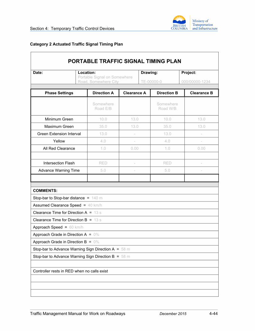
Section 4: Temporary Traffic Control Devices
Traffic Management Manual for Work on Roadways December 2015 4-44
Category 2 Actuated Traffic Signal Timing Plan
PORTABLE TRAFFIC SIGNAL TIMING PLAN
Date:
Location: Portable Signal on Somewhere Road, Somewhere City
Drawing: TE-00000-0
Project: 000/00000-1234
Phase Settings Direction A Clearance A Direction B Clearance B
Somewhere Road E/B
Somewhere Road W/B
Minimum Green 10.0 13.0 10.0 13.0
Maximum Green 35.0 13.0 35.0 13.0
Green Extension Interval 13.0 - 13.0 -
Yellow 4.0 - 4.0 -
All Red Clearance 1.0 0.00 1.0 0.00
Intersection Flash RED - RED -
Advance Warning Time 5.0 - 5.0 -
COMMENTS:
Stop-bar to Stop-bar distance = 140 m
Assumed Clearance Speed = 40 km/h
Clearance Time for Direction A = 13 s
Clearance Time for Direction B = 13 s
Approach Speed = 60 km/h
Approach Grade in Direction A = 0%
Approach Grade in Direction B = 0%
Stop-bar to Advance Warning Sign Direction A = 58 m
Stop-bar to Advance Warning Sign Direction B = 58 m
Controller rests in RED when no calls exist

Section 4: Temporary Traffic Control Devices
Traffic Management Manual for Work on Roadways December 2015 4-45
Example of Actuated Portable Traffic Signal Timing Calculations (Engineering Analysis Required)
Work Zone Characteristics:
Work zone length = 60 m Approach speed = 60 km/h = 16.7 m/s Assumed clearance speed = 40 km/h Grade = 0% (both approach directions) Stop bar distance from work zone (west side) = 40 m Stop bar distance from work zone (east side) = 40 m Therefore, stop bar to stop bar distance = 60 + 40 + 40 = 140 m
Portable Traffic Signal:
Select Max Green Time of 35 s 35 s is often a good starting point for Max Green Time.
However, based on traffic volumes and local knowledge, the Traffic Engineer may adjust the Max Green Time to ensure that there is no undue vehicle delay.
Clearance Time .
Where: R = all Red Clearance Times (s)
V = travel speed through work zone (km/h)
=3.6(140m)
40 km/h D = distance between stop bars (m)
=13 s
Yellow Time = 4 s
Advance Warning Flashers:
Distance (stop bar to advance warning flasher) = 58 m for 60 km/h approach speed and 0 % grade.
Advance Warning Time =D+Dρ
V Where: D = distance of flasher to signal (m)
Dρ = minimum perception distance = 21.3 m V = posted speed limit (m/s)
=58m+21.3m
16.7m/s
5s

Section 4: Temporary Traffic Control Devices
Traffic Management Manual for Work on Roadways December 2015 4-46
4.9 Lighting Devices
Lighting devices may be used in work zones when specified in this Manual or by the Road Authority. They may supplement channelizing devices, signs, and barriers, and/or be used to illuminate equipment or work activity areas.
4.9.1 Flashing Vehicle Lights All work, buffer, and shadow vehicles stationed in or near travel lanes should be equipped with 4-way (emergency) flashers and 360-degree flashing yellow lights. They should be activated whenever a vehicle is positioned such that it could influence traffic.
4.9.2 Yellow Warning Lights Yellow warning lights are portable yellow lights commonly used during night time hours to supplement other traffic control devices. There are four types of yellow warning lights—Types A, B, C, and D. Types A and B should not normally be mixed when used in a series.
Figure 4.23: Type A & C Yellow Warning Light
Type A Low-Intensity flashing warning lights may be used to supplement signs and channelizing devices such as barriers, barricades (particularly Type 1), and flexible drums, and for marking specific hazards and outlining long-duration work activity areas.
Type B High-Intensity flashing warning lights are used during daylight and night-time hours. They operate 24 hours per day and may be mounted on advance warning signs or on independent supports. They may also be used on barricades, barriers, and channelizing devices if they can be dimmed during night-time use to reduce driver sensitivity to brightness.
Type B lights should be visible for at least 300 metres in clear daylight conditions. Flags may be substituted for Type B lights in day-time applications.
Type C Steady-Burn and Type D 360-Degree Steady Burn warning lights may be used to supplement delineation of the edge of the roadway where multiple devices are used. They may also be used to delineate a work activity area or to run along the edge of a closed lane or shoulder. When used to delineate a curve, they should be used only on devices on the outside of the curve.
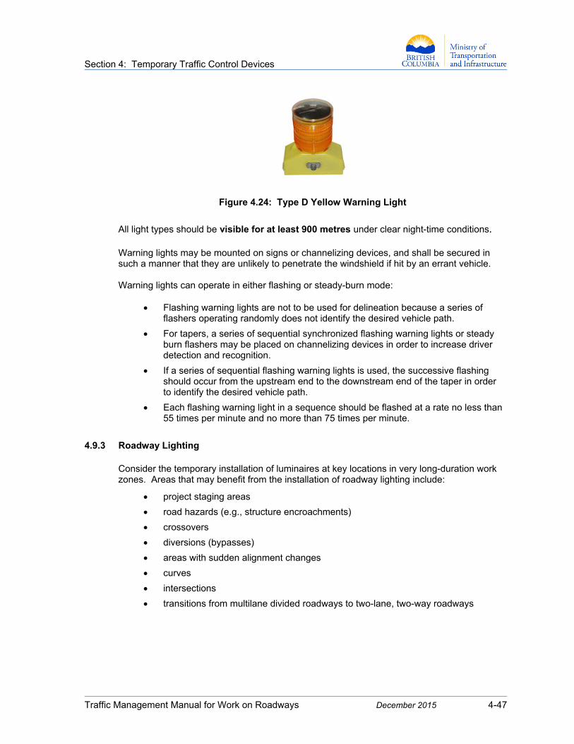
Section 4: Temporary Traffic Control Devices
Traffic Management Manual for Work on Roadways December 2015 4-47
Figure 4.24: Type D Yellow Warning Light
All light types should be visible for at least 900 metres under clear night-time conditions.
Warning lights may be mounted on signs or channelizing devices, and shall be secured in such a manner that they are unlikely to penetrate the windshield if hit by an errant vehicle. Warning lights can operate in either flashing or steady-burn mode:
Flashing warning lights are not to be used for delineation because a series of flashers operating randomly does not identify the desired vehicle path.
For tapers, a series of sequential synchronized flashing warning lights or steady burn flashers may be placed on channelizing devices in order to increase driver detection and recognition.
If a series of sequential flashing warning lights is used, the successive flashing should occur from the upstream end to the downstream end of the taper in order to identify the desired vehicle path.
Each flashing warning light in a sequence should be flashed at a rate no less than 55 times per minute and no more than 75 times per minute.
4.9.3 Roadway Lighting
Consider the temporary installation of luminaires at key locations in very long-duration work zones. Areas that may benefit from the installation of roadway lighting include:
project staging areas
road hazards (e.g., structure encroachments)
crossovers
diversions (bypasses)
areas with sudden alignment changes
curves
intersections
transitions from multilane divided roadways to two-lane, two-way roadways
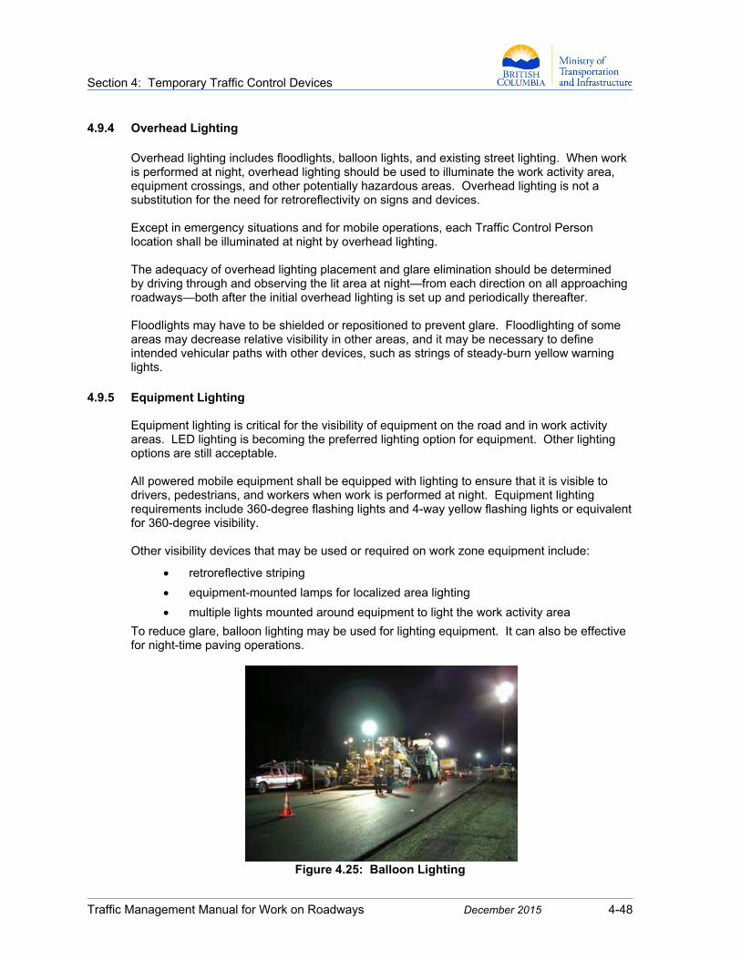
Section 4: Temporary Traffic Control Devices
Traffic Management Manual for Work on Roadways December 2015 4-48
4.9.4 Overhead Lighting Overhead lighting includes floodlights, balloon lights, and existing street lighting. When work is performed at night, overhead lighting should be used to illuminate the work activity area, equipment crossings, and other potentially hazardous areas. Overhead lighting is not a substitution for the need for retroreflectivity on signs and devices. Except in emergency situations and for mobile operations, each Traffic Control Person location shall be illuminated at night by overhead lighting. The adequacy of overhead lighting placement and glare elimination should be determined by driving through and observing the lit area at night—from each direction on all approaching roadways—both after the initial overhead lighting is set up and periodically thereafter. Floodlights may have to be shielded or repositioned to prevent glare. Floodlighting of some areas may decrease relative visibility in other areas, and it may be necessary to define intended vehicular paths with other devices, such as strings of steady-burn yellow warning lights.
4.9.5 Equipment Lighting
Equipment lighting is critical for the visibility of equipment on the road and in work activity areas. LED lighting is becoming the preferred lighting option for equipment. Other lighting options are still acceptable. All powered mobile equipment shall be equipped with lighting to ensure that it is visible to drivers, pedestrians, and workers when work is performed at night. Equipment lighting requirements include 360-degree flashing lights and 4-way yellow flashing lights or equivalent for 360-degree visibility. Other visibility devices that may be used or required on work zone equipment include:
retroreflective striping
equipment-mounted lamps for localized area lighting
multiple lights mounted around equipment to light the work activity area
To reduce glare, balloon lighting may be used for lighting equipment. It can also be effective for night-time paving operations.
Figure 4.25: Balloon Lighting

Section 4: Temporary Traffic Control Devices
Traffic Management Manual for Work on Roadways December 2015 4-49
4.10 Fencing and Screens
4.10.1 Work Zone Fencing
Work zone fencing can be used to:
identify the work area
protect the public from the work area
protect the work area from road users
mark the edge of work zones
identify the travel path for drivers, cyclists, and pedestrians
Removable Chain Link Panels Snow Fence with Retroreflective Stripes
Chain Link Panels on Concrete Roadside Barrier
Figure 4.26: Work Zone Fencing

Section 4: Temporary Traffic Control Devices
Traffic Management Manual for Work on Roadways December 2015 4-50
4.10.2 Work Zone Screens and Barrier Screens In long-duration work zones on multilane highways where median and roadside work activities may impact traffic operations and cause delays, screens are useful for blocking the road user’s view of activities, which can be distracting. Screens may further improve safety and traffic flow by reducing headlight glare from oncoming vehicle traffic. Screens may be mounted on the top of temporary traffic barriers that separate two-way vehicle traffic. They shall not be mounted where they might adversely affect vehicle operations or driver sight distances.
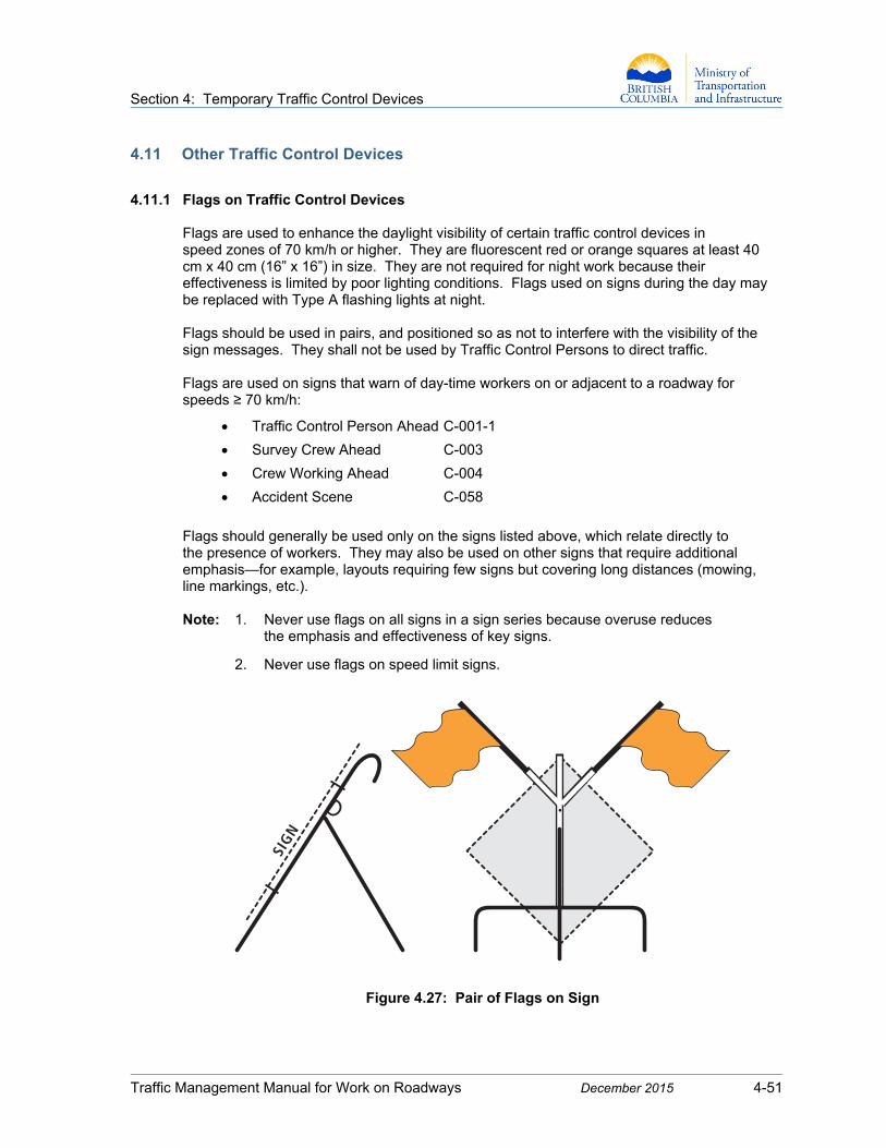
Section 4: Temporary Traffic Control Devices
Traffic Management Manual for Work on Roadways December 2015 4-51
4.11 Other Traffic Control Devices
4.11.1 Flags on Traffic Control Devices
Flags are used to enhance the daylight visibility of certain traffic control devices in speed zones of 70 km/h or higher. They are fluorescent red or orange squares at least 40 cm x 40 cm (16” x 16”) in size. They are not required for night work because their effectiveness is limited by poor lighting conditions. Flags used on signs during the day may be replaced with Type A flashing lights at night. Flags should be used in pairs, and positioned so as not to interfere with the visibility of the sign messages. They shall not be used by Traffic Control Persons to direct traffic. Flags are used on signs that warn of day-time workers on or adjacent to a roadway for speeds ≥ 70 km/h:
Traffic Control Person Ahead C-001-1
Survey Crew Ahead C-003
Crew Working Ahead C-004
Accident Scene C-058
Flags should generally be used only on the signs listed above, which relate directly to the presence of workers. They may also be used on other signs that require additional emphasis—for example, layouts requiring few signs but covering long distances (mowing, line markings, etc.). Note: 1. Never use flags on all signs in a sign series because overuse reduces
the emphasis and effectiveness of key signs.
2. Never use flags on speed limit signs.
Figure 4.27: Pair of Flags on Sign
SIGN

Section 4: Temporary Traffic Control Devices
Traffic Management Manual for Work on Roadways December 2015 4-52
4.11.2 Sand Bags/Weights Sand bags/weights may be used in work zones to support and/or stabilize the base area of signs and channelizing devices. Windy areas, higher-speed roadways, and narrow and sloped areas impact the stability of traffic control devices. The weights should be placed near the road surface where they cannot become projectiles. Sand bags shall not be used as a channelizing device.
4.11.3 Speed Reader Boards Speed reader boards (SRB) are electronic changeable speed display signs capable of detecting and displaying the speed of approaching vehicles in real-time via radar speed detection. SRB come either as trailer mounted units or pole mounted units. SRB may be used for:
long-duration work zones (i.e., night-time work or more than one day-time shift)
work zones that use Traffic Control Persons
highway projects when stipulated by provisions in the project documents
1. Deployment Guidelines
1. SRBs should be positioned downstream of the regulatory speed sign to affirm a
construction speed zone.
2. SRBs are placed approximately 100 to 200 metres in advance of the work activity area.
3. When used in advance of Traffic Control Person setups, the location of the speed reader board should follow the placement guidelines illustrated in Figure 4.29 A: Long-Duration Lane Closure with TCPs and Speed Reader Boards – Two-Lane, Two-Way Roadway.
4. On multilane highways, speed reader boards should not be placed close to merge areas and ramp areas.
5. Where work zones are divided into several work activity areas or are more than 1500 metres long, two or more speed reader boards may be used (per direction) to reaffirm and maintain speed reductions, separated by at least 300 metres.
6. Speed reader boards should be inspected for sight lines and for shadowing created by structures or construction signs to ensure sign visibility and effective operation.
7. A speed reader board should be delineated/protected using drums or tube markers/ delineators, with at least three markers/delineators on the upstream side of the speed reader board.

Section 4: Temporary Traffic Control Devices
Traffic Management Manual for Work on Roadways December 2015 4-53
2. Operational Guidelines
1. SRB should include the words YOUR SPEED or similar text, together with the
numeric electronic display. The text may be non-electronic.
2. SRB shall be in operation only when the construction speed limit is in effect and workers are present on the roadway.
3. The speed reader board shall be programmed in relation to the construction speed limit.
4. If no vehicles are approaching the speed reader board, the display should be blank.
5. The electronic display may be programmed to flash and/or display the message SLOW DOWN when the vehicle speed exceeds 10 km/h over the speed limit. It shall not flash for speeds less than 10 km/h over the speed limit. The flash rate shall be a maximum of 50 cycles per minute. Strobe-type light enhancements are not permitted.
6. When the vehicle speed exceeds 40 km/h over the speed limit, the numeric display should be programmed to go blank or display the message SLOW DOWN.
7. The radar in the speed reader board should detect an approaching vehicle no more than 10 seconds before the vehicle reaches the radar unit’s position. Detection should not occur until the vehicle has entered the construction speed zone.
Figure 4.28: Speed Reader Board
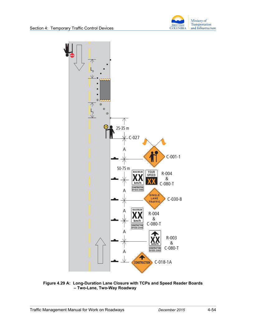
Section 4: Temporary Traffic Control Devices
Traffic Management Manual for Work on Roadways December 2015 4-54
Figure 4.29 A: Long-Duration Lane Closure with TCPs and Speed Reader Boards – Two-Lane, Two-Way Roadway
C-018-1A
C-030-8
C-001-1
LD
LS
A
A
A
A
A
50-75 m
C-027
25-35 m
R-004&
C-080-T
R-004&
C-080-T
R-003&
C-080-T
xx
xx
xx
xx

Section 4: Temporary Traffic Control Devices
Traffic Management Manual for Work on Roadways December 2015 4-55
Figure 4.29 B: Freeway/Multilane Median Crossover with Speed Reader Board
R-004&
C-022
R-003&
C-022
xx
xx
xx
xx
A
C-130-R
C-130-R& C-130-T
A
A
A
A
C-018-1A
WORKACTIVITY
AREA
LD
LL
LDLT
LM

Section 4: Temporary Traffic Control Devices
Traffic Management Manual for Work on Roadways December 2015 4-56
4.11.4 Temporary Rumble Strips Temporary rumble strips may be used to alert road users to a changing roadway environment that requires extraordinary caution. They may also be used as an audible vehicle detection system for workers adjacent to the roadway.
They are surface placed, raised strips, which are placed perpendicular to the direction of travel. When a vehicle passes over the strips, the noise and vibration draw the driver’s attention to features such as signs, unexpected alignment changes, or potential stop conditions.
Installation Guidelines:
1. Spacing between temporary rumble strips should be 3.0 m, and their width should
extend across the travel lane. A sign warning drivers of the rumble strips should be placed in advance of the installation (see Figure 4.31: Layout of Temporary Rumble Strips).
2. Temporary rumble strips may be white, yellow, black, or orange, and contrast the colour of the roadway.
3. Temporary rumble strips should be placed sufficiently in advance of the condition to allow road users to respond to the warning.
4. Temporary rumble strips should not be placed:
within intersections
through pedestrian crossings
on sharp horizontal or vertical curves
within marked bicycle lanes or on roadways used by cyclists unless a clear path at least 1.0 m wide is provided at each edge of the roadway or on each paved shoulder
Figure 4.30: Temporary Rumble Strips

Section 4: Temporary Traffic Control Devices
Traffic Management Manual for Work on Roadways December 2015 4-57
Figure 4.31: Layout of Temporary Rumble Strips
C-018-1A
C-017
C-030-8
C-027
C-001-1
A
A
A
A
~25-35 m
RUMBLE STRIPS DETAIL
WORKACTIVITY
AREA
3.0 m
3.0 m

Section 4: Temporary Traffic Control Devices
Traffic Management Manual for Work on Roadways December 2015 4-58
4.11.5 Shadow Vehicles Shadow vehicles are used to provide mobile advance warning for operations where a work vehicle blocks or encroaches into a travel lane that has not been closed to traffic. There may be more than one shadow vehicle for a continuously-moving work zone, with one shadow vehicle positioned as far as possible onto the shoulder (left or right) in advance of the work vehicle. Two shadow vehicles are typically required on multilane divided roadways with speeds ≥ 70 km/h. The shadow vehicle operator(s) and the work vehicle operator should be in communication with one another. Operations where shadow vehicles may be used include, but are not limited to:
pavement marking and striping
hydro-seeding
sweeping
flushing
pothole patching
mowing
The factors involved in determining the requirement for shadow vehicles include:
exposure of workers to traffic
speed of traffic relative to speed of work vehicle
traffic volumes and number of lanes
highway classification
shoulder width
sight distance
weather conditions
Shadow vehicle distances should be adjusted for horizontal and vertical curves so that the vehicle is clearly visible to traffic approaching the curves. The distance between shadow vehicles and working equipment may require periodic adjustment to prevent drivers from crossing or driving into the lane between the shadow vehicle and the work area or equipment. Shadow vehicles shall be equipped with a flashing arrow board (FAB) and a 360-degree flashing yellow light and 4-way flashers. If a flashing arrow board is used on a two-lane, two-way roadway, it should show only a non-directional warning display. It shall never display an arrow that directs traffic into a lane that could be occupied by opposing traffic. The shadow vehicle may be equipped with a rear-mounted crash attenuator. This may be required for specific types of work activities for certain highway classifications, or as specified by the Road Authority. Vehicle-mounted crash attenuators are often used on shadow vehicles in mobile, high-speed (≥ 70 km/h) operations.
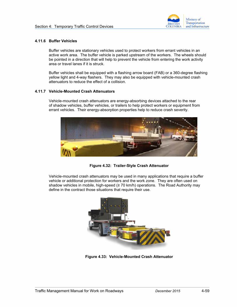
Section 4: Temporary Traffic Control Devices
Traffic Management Manual for Work on Roadways December 2015 4-59
4.11.6 Buffer Vehicles Buffer vehicles are stationary vehicles used to protect workers from errant vehicles in an active work area. The buffer vehicle is parked upstream of the workers. The wheels should be pointed in a direction that will help to prevent the vehicle from entering the work activity area or travel lanes if it is struck. Buffer vehicles shall be equipped with a flashing arrow board (FAB) or a 360-degree flashing yellow light and 4-way flashers. They may also be equipped with vehicle-mounted crash attenuators to reduce the effect of a collision.
4.11.7 Vehicle-Mounted Crash Attenuators Vehicle-mounted crash attenuators are energy-absorbing devices attached to the rear of shadow vehicles, buffer vehicles, or trailers to help protect workers or equipment from errant vehicles. Their energy-absorption properties help to reduce crash severity.
Figure 4.32: Trailer-Style Crash Attenuator
Vehicle-mounted crash attenuators may be used in many applications that require a buffer vehicle or additional protection for workers and the work zone. They are often used on shadow vehicles in mobile, high-speed (≥ 70 km/h) operations. The Road Authority may define in the contract those situations that require their use.
Figure 4.33: Vehicle-Mounted Crash Attenuator

Section 4: Temporary Traffic Control Devices
Traffic Management Manual for Work on Roadways December 2015 4-60
4.11.8 Temporary Crash Attenuators on Barriers
Crash attenuators—also known as crash cushions or impact attenuators—are systems that absorb energy when struck by an errant vehicle, either through deceleration or deflection. These devices reduce the effects of crashes from the exposed ends of barriers, bridge piers, fixed objects, and other obstacles. Detailed crash attenuator information is available in the American Association of State Highway and Transportation Officials’ (AASHTO) Roadside Design Guide. Requirements for the use of temporary crash attenuators are defined in the Ministry’s special provisions for highways projects, or by the Road Authority.
1. Crash attenuators used on Provincial highways shall meet the TL-2 and TL-3 crash test levels for speed as specified in National Cooperative Highway Research Program’s NCHRP Report 350.
2. Unless otherwise approved by the Road Authority, the selected test level shall match the original or intended regulatory speed at which the highway will operate when the work zone is removed.
3. Crash attenuators should be inspected periodically to verify that they have not been hit or damaged. Damaged crash attenuators shall be repaired or replaced to maintain their crash-worthiness.
4. For Ministry projects, the Regional Traffic Engineer will assess the need for crash attenuators based on several factors. These include, but are not limited to:
speed
highway classification
number of lanes
volume
geometrics
site constraints
obstacle to be protected

Section 4: Temporary Traffic Control Devices
Traffic Management Manual for Work on Roadways December 2015 4-61
4.11.9 Pilot Cars for Work Zones
Section 4.11.9 deals with pilot cars that are used to guide traffic through construction zones and work areas.
For information on piloting extraordinary loads, see Division 8 (Pilot Cars and Signs) in the Commercial Transport Regulations and Chapter 8 of the Commercial Transport Procedure Manual:
http://www.bclaws.ca/Recon/document/ID/freeside/30_78
http://www.th.gov.bc.ca/cvse/ctpm/Chapter_8.pdf
For the purposes of this Manual, a pilot car is a vehicle marked with warning signs and lights that is used to guide a queue of vehicles through a work zone or detour regulated by Traffic Control Persons or by temporary signals for which the pilot car operator has full control of the signal operation. The length and complexity of the work zone makes navigation difficult for drivers. (e.g., where there is a substantial change in alignment). When deciding whether or not to use a pilot car operation, it is important to consider the type of work, traffic volume, road alignment, and access points within the work zone. A pilot car should have four or more wheels, seating for two or more persons, and be capable of transporting pedestrians or cyclists through the work zone. 1. Communication with Stakeholders
It is important to communicate with the affected stakeholders when initiating a pilot car operation in an area with accesses and driveways via:
written notification of the dates and times when work will take place
written instructions for safely joining and leaving the traffic stream when entering and leaving the location of the business, residence, or institution
contact information for the Prime Contractor
2. Planning and Operations
The plan to use a pilot car should be assessed before the project commences, taking into account the nature of the work zone. For example, if there are complex access issues, a strategy should be developed for keeping track of vehicle entries and departures from the queue.
A pilot car shall be operated in a manner that ensures the highest level of safety for road users and workers. The travel speed should not permit gaps to develop between the vehicles being led, and should not contribute to tar splatter or the creation of dust in the work zone.

Section 4: Temporary Traffic Control Devices
Traffic Management Manual for Work on Roadways December 2015 4-62
Traffic Control Persons and pilot car operators should remain in radio communication throughout the work zone, with Traffic Control Persons regulating traffic:
at each end of the work zone
at every intersection that may require it between Traffic Control Persons
at every other location where needed to ensure safety
when an assessment dictates it, at every business access location that routinely has customers stopping between the primary Traffic Control Persons at either end of the pilot car zone
3. Pilot Car Warning Lights
Four-way flashers and 360-degree rotating yellow warning lights shall be used on pilot cars. Warning lights should be directly wired to the vehicle’s electrical system. Arrow sticks are an acceptable alternative to the 360-degree rotating yellow warning lights. The lights should be used only when the pilot car is operating.
4. Pilot Car Signs
The Pilot Car C-049 sign is usually double-sided and should have the words PILOT CAR on one side for approaching vehicles and PILOT CAR – DO NOT PASS on the other side for following vehicles. The sign should be positioned on the pilot car so that it is visible to drivers of vehicles approaching from both directions, and shall be kept in a vertical position to ensure good viewing from both directions. Pilot cars may use two separate signs with the same messaging indicated above. Another option is the Pilot Car C-048-2 sign, which displays PILOT CAR on both sides and fits within manufactured overhead racks. Shoulder-mounted FOLLOW PILOT CAR signs should be positioned so that approaching drivers are notified of the pilot car operation. Additional FOLLOW PILOT CAR signs may be required so that signs are positioned beyond the end of the expected or known vehicle queues resulting from pilot car operations.

Section 4: Temporary Traffic Control Devices
Traffic Management Manual for Work on Roadways December 2015 4-63
C-049-x
900 x 900 mm
C-048-1-DS
1200 x 900 mm
C-048-2 1830 x 305 mm
Figure 4.34: Pilot Car Signs
5. Pilot Car Radio Communications
Pilot cars should have an electronic device that allows all pilot car operators and all Traffic Control Persons to communicate effectively with each other over the length of the pilot car operation. Communications should be on the same channel or frequency, and should be switched on at all times during pilot car operations.
6. Pilot Car Traffic Control
Pilot car operators are not authorized to direct traffic. Their role is to guide traffic through a work zone once that traffic has been directed to follow them by an authorized Traffic Control Person. Pilot car operators may also position their vehicles to control vehicle access to the work zone. If a pilot car operator is to carry out Traffic Control Person operations, that operator shall first be trained as a Traffic Control Person in a manner that is acceptable to WorkSafeBC, and shall perform Traffic Control Person duties in a manner that complies with WorkSafeBC and Road Authority requirements.

Section 4: Temporary Traffic Control Devices
Traffic Management Manual for Work on Roadways December 2015 4-64
This page is intentionally blank.

Section 5: Traffic Control Persons (TCPs)
Traffic Management Manual for Work on Roadways December 2015 5-i
PART B – TRAFFIC CONTROL
Section 5: Traffic Control Persons (TCPs)
Contents
5.1 Roles and Responsibilities ........................................................................ 5-1
5.1.1 Traffic Control Supervisor ................................................................ 5-1 5.1.2 Traffic Control Persons (TCPs) ....................................................... 5-2 5.2 Use of TCPs in Work Zones....................................................................... 5-3 5.3 Minimum Requirements for TCPs ............................................................. 5-4
5.3.1 Physical and Mental Requirements ................................................. 5-4 5.3.2 Training and Certification ................................................................ 5-4 5.4 Work Zone Apparel and Equipment ......................................................... 5-5
5.4.1 TCP Apparel and Equipment ........................................................... 5-5 1. Basic Requirements ................................................................ 5-5 2. Day-Time and Night-Time Apparel .......................................... 5-6 3. Additional Requirements for Night Operations ........................ 5-7 4. Night Lighting .......................................................................... 5-7 5. Optional Equipment ................................................................. 5-7 6. Lettering and ID Patches ......................................................... 5-7 5.4.2 Apparel Retroreflectivity for TCPs ................................................... 5-7 5.4.3 Apparel for Other Onsite Workers ................................................... 5-9 5.4.4 Apparel Labelling for All Onsite Workers ....................................... 5-10 5.5 TCP Communications .............................................................................. 5-11
5.5.1 Fundamental Principles ................................................................. 5-11 5.5.2 TCP Radios ................................................................................... 5-13 1. Radio-Based Tasks ............................................................... 5-13 2. Rules for Radio Use .............................................................. 5-13 3. Radio Frequencies ................................................................ 5-13 5.6 TCP Positioning and Signals................................................................... 5-14
5.6.1 Hazard and Risk Assessment ....................................................... 5-14 5.6.2 Positioning Rules for TCPs ........................................................... 5-14 5.6.3 Positioning Rules for TCPs in Intersections .................................. 5.15 5.6.4 Temporary Stop Bars .................................................................... 5-16 5.6.5 TCP Signals ................................................................................... 5-17 1. Signal for Stopping Traffic ..................................................... 5-17 2. Signal for Slowing Traffic ....................................................... 5-17 3. Stopping Sight Distances ...................................................... 5-18
Section 5: Traffic Control Persons (TCPs)
Traffic Management Manual for Work on Roadways December 2015 5-ii
5.7 TCP Safety ................................................................................................ 5-19
5.7.1 Ability to Make Evasive Manoeuvers ............................................ 5-19 5.7.2 Management of Approaching Vehicle Speeds .............................. 5-19 1. Speed Management Delineation .......................................... 5-19 2. Speed Management at Night ................................................ 5-20 5.7.3 Prohibitions for TCPs While Actively Controlling Traffic ............... 5-20 5.8 Emergency Procedures ........................................................................... 5-21
5.8.1 Passage of Emergency Vehicles and Personnel .......................... 5-21 5.8.2 Traffic Control at Emergency Scenes ........................................... 5-22

Section 5: Traffic Control Persons (TCPs)
Traffic Management Manual for Work on Roadways December 2015 5-1
PART B – TRAFFIC CONTROL
Section 5: Traffic Control Persons (TCPs) 5.1 Roles and Responsibilities
For information on management responsibilities related to traffic control, see Section 1.2: Road Authority and Prime Contractor Responsibilities.
5.1.1 Traffic Control Supervisor The Prime Contractor shall designate a Traffic Control Supervisor who is qualified to assume the responsibilities of this function. It cannot be the Site Supervisor, Superintendent, or Foreman unless the designation is authorized by the Road Authority.
The Traffic Control Supervisor may be an employee of the Prime Contractor or a sub-contractor to the Prime Contractor. It may be the Traffic Control Manager for the project or an onsite Traffic Control Person if circumstances allow. If the traffic management responsibilities for the project require full-time or frequent attention, a different person should be assigned to this role.
In general, the Traffic Control Supervisor is responsible for ensuring that:
oversee traffic control operations, ensuring traffic control is executed in accordance with the Traffic Control Plan, and updated as necessary.
ensure compliance with Part 18 of WorkSafeBC’s Occupational Health and Safety Regulation regarding supervision of Traffic Control Persons in the work zone
provide direction to Traffic Control Persons
required traffic control devices are in place
signs are checked, maintained, and moved as required
daily traffic control setups are documented, and changes are identified in the Traffic Control Plan or log book
traffic concerns are reported to the Traffic Control Manager or Site Supervisor
each member of the traffic control crew wears the required personal protective clothing and equipment (see Section 5.4: Work Zone Apparel and Equipment)
The Traffic Control Supervisor shall also ensure that all TCPs are:
carrying evidence of current TCP certification
equipped with all necessary equipment, including, radios, spare batteries, chargers, and red signalling wand
performing traffic control duties competently and safely
positioned in safe locations that are clear of potential environmental hazards, such as a slide or avalanche
provided with rest breaks

Section 5: Traffic Control Persons (TCPs)
Traffic Management Manual for Work on Roadways December 2015 5-2
If two or more TCPs work as a team, the employer of the traffic control personnel and the Traffic Control Supervisor should ensure that the responsibility for coordinating changes in traffic flow is assigned appropriately. The Traffic Control Supervisor shall have TCP certification in order to assume the duties of a TCP and direct traffic.
5.1.2 Traffic Control Persons (TCPs)
Depending on the project category and complexity, and in collaboration with the Prime Contractor, TCPs may be required to prepare, review, amend, and document Traffic Control Plans as part of their daily activities. In order to do so, they shall carry valid TCP certification on the work site at all times, and have a good working knowledge of this Manual. TCPs shall communicate instructions and directions to drivers effectively by using standard traffic control motions and signals that are precise and deliberate to be clearly understood by road users. TCPs quickly become familiar with their work zone, and should try to assess the layout through the eyes of a road user who is arriving at the zone in the worst foreseeable conditions. This will help them to anticipate traffic control issues and identify required changes to the Traffic Control Plan. TCP training and performance should emphasize:
the importance of the job
alertness and attentiveness
the need for a courteous but firm manner
proper TCP positioning in relation to the work activity area in order to achieve effective traffic control and ensure the safety of the public, workers, equipment, and all TCPs
sufficient discipline to prevent others from loitering near the TCP location
sufficient discipline to remain in position until relieved by other personnel or until the conflict being controlled no longer exists
the requirement to remove or cover Traffic Control Person Ahead C-001-1 signs whenever TCPs are not actively regulating traffic
the requirement to comply with Part 18 of WorkSafeBC’s Occupational Health and Safety Regulation regarding personal protective equipment (see Section 5.4: Work Zone Apparel and Equipment) and traffic control signals (see Section 5.6: TCP Positioning and Signals)
Among other requirements specified in Part 18.4 of WorkSafeBC’s Occupational Health and Safety Regulation, employers and supervisors should ensure that:
Traffic control arrangements and procedures for the work are made known to all personnel involved in the work.
Required traffic control devices and procedures are in place before the work starts and are removed when they are no longer required.
Any person assigned to be a TCP is adequately trained in a manner acceptable to WorkSafeBC, and performs effectively in accordance with the traffic control arrangements and procedures for the work.

Section 5: Traffic Control Persons (TCPs)
Traffic Management Manual for Work on Roadways December 2015 5-3
5.2 Use of TCPs in Work Zones
TCPs are used only when all other traffic control methods are considered
inadequate to warn, direct, and regulate road users within a work zone.
TCPs are used to regulate traffic within a work zone, thereby preventing conflicts between the movements of pedestrians, vehicles, workers, and work zone equipment. TCPs shall not control traffic within speed limits greater than 70 km/h. Common applications for TCPs include:
control of alternating one-way traffic through sections of a two-way road that is temporarily reduced to one lane (single lane alternating traffic or SLAT)
stopping public traffic to permit equipment to cross or enter onto a road, structure, or other work zone feature
providing information to drivers or pedestrians regarding road closures, wait times, route options, etc.
One or both TCPs may be omitted in the following situations:
1. The self-regulated section does not extend through an intersection.
2. Where an open, one-lane section is sufficiently short (e.g., a spot obstruction), sight distance is adequate, and traffic volumes are light.
If one TCP is omitted, the Traffic Control Person Ahead C-001-1 signs remain to warn of the one TCP ahead.
If both TCPs are omitted, the Traffic Control Person Ahead C-001-1 signs are removed and a Yield To Oncoming Traffic R-056 sign is posted in the closed lane or the lane affected by the works.
3. A temporary traffic signal may be used instead of TCPs to control traffic on sections of one-lane, two-way roadways (see Section 4.8: Portable Traffic Signals).
4. TCPs are not generally required as a traffic control measure for reducing speed or for reducing the number of lanes on multilane roads.

Section 5: Traffic Control Persons (TCPs)
Traffic Management Manual for Work on Roadways December 2015 5-4
5.3 Minimum Requirements for TCPs
5.3.1 Physical and Mental Requirements
TCPs should be physically and mentally prepared to do the required work, and should exhibit these characteristics:
good vision
good hearing
alertness and mature judgement
intelligence and common sense
pleasant, cooperative disposition
sense of responsibility for the safety of workers and the public
5.3.2 Training and Certification
TCPs shall receive approved training, pass an examination, and be certified before they are assigned to work within a work zone.
TCPs shall:
have valid proof of training or certification issued by a recognized training agency as determined by WorkSafeBC
carry their certification at all times while on the job
present their certification to the appropriate authorities on demand
TCPs should have these proficiencies:
knowledge of vehicle operations, such as stopping distances, turning radii, etc.
knowledge of basic regulatory requirements governing drivers
understanding of basic traffic signs and the rules of the road
understanding of driver expectations
A Class 5 driver’s licence may help to provide information about these proficiencies.
Section 5: Traffic Control Persons (TCPs)
Traffic Management Manual for Work on Roadways December 2015 5-5
5.4 Work Zone Apparel and Equipment
5.4.1 TCP Apparel and Equipment
Personal protective clothing and equipment for TCPs shall comply with Parts 8 and 18 of WorkSafeBC’s Occupational Health and Safety Regulations and other standards as identified below. 1. Basic Requirements
TCPs shall have the following required material with them on the job at all times:
STOP or SLOW C-027 Paddle: An extension pole that is 1.3 to 2.1 metres long is optional.
Traffic Control Person Ahead C-001-1 Sign: The sign shall be removed or covered when TCPs are not actively controlling traffic.
Safety Headgear: TCP hard hats shall comply with one of these standards:
- CSA Standard CAN/CSA-Z94.1-92, Industrial Protective Headwear
- ANSI Standard Z89.1-1986, American National Standard for Personnel Protection – Protective Headwear for Industrial Workers Requirements
- Japanese Industrial Standard JIS T8131-1990, Industrial Safety Helmets for Class AB or ABE Headgear
Hard hats shall be of a high-visibility colour with a band of retroreflective tape across the top from front to back and on the sides.
- WorkSafeBC permits fluorescent yellow-green, fluorescent orange-red, and fluorescent red colours.
- The hard hat shall have retroreflective material across the top from front to back and on the sides to make it clearly visible to drivers approaching from any angle.
Safety Footwear: TCP footwear shall be CSA-compliant Grade 1 safety footwear (green triangular CSA patch on the outside, green rectangular label on the inside).
Safety Apparel: TCPs shall wear Class 3 garments that comply with both the CSA Z96-02 standard and Section 18.9 of WorkSafeBC’s Occupational Health and Safety Regulation.
See also Section 5.4.2: Apparel Retroreflectivity for TCPs.

Section 5: Traffic Control Persons (TCPs)
Traffic Management Manual for Work on Roadways December 2015 5-6
2. Day-Time and Night-Time Apparel
Figure 5.1: TCPs with Fluorescent Yellow-Green and Fluorescent Orange-Red Vests
Figure 5.2: TCPs with Fluorescent Yellow-Green and Fluorescent Orange-Red Coveralls
FRONT BACK
FRONT BACK

Section 5: Traffic Control Persons (TCPs)
Traffic Management Manual for Work on Roadways December 2015 5-7
3. Additional Requirements for Night Operations
flashlight with red signalling wand
spare batteries
two-way radios
4. Night Lighting
TCP stations shall be illuminated at night. If street lighting is available, TCPs should stand below the light to maximize front-of-body illumination. If temporary overhead lighting is being used, it shall not subject approaching drivers to excessive glare.
5. Optional Equipment
CSA-approved safety sunglasses or eye protection where required
rain gear meeting Class 3 retroreflectivity requirements
6. Lettering and ID Patches
Lettering and ID patches that are not retroreflective may be placed on the garment, provided that they do not cover an area greater than 100 cm2 and do not cover any part of the mandatory retroreflective stripes/bands. Retroreflective lettering or ID patches that meet the requirements of Tables 5, 6, and 7 in the CSAZ97-02 standard shall not cover an area greater than 500 cm2 and may be placed anywhere on the garment as long as the positioning does not obscure the recognizable pattern of the stripes/bands. Note: For work on Provincial roadways, the Ministry has adopted a high-visibility
standard for worker apparel that exceeds WorkSafeBC’s retroreflectivity standard.
This standard provides both adequate retroreflectivity and contrasting colour, and applies to all workers on all Ministry projects.
5.4.2 Apparel Retroreflectivity for TCPs
TCPs shall wear Class 3 safety garments that comply with both the CSA Z96-02 standard and the WorkSafeBC requirement. At minimum, Class 3 high-visibility material shall fully cover the upper torso (front, back, sides, and over shoulders) and shall include bands encircling both arms and both legs. Acceptable colours for background material on these high-visibility safety garments are fluorescent yellow-green and fluorescent orange-red (the orange-red is often labelled fluorescent orange). These garments require a contrasting-colour fluorescent stripe that is at least 100 mm (4”) wide. Acceptable colours for the contrasting stripe are also fluorescent yellow-green and fluorescent orange-red. The retroreflective bands used on these garments shall be at least 50 mm (2”) wide and in a colour that contrasts with the background colour.
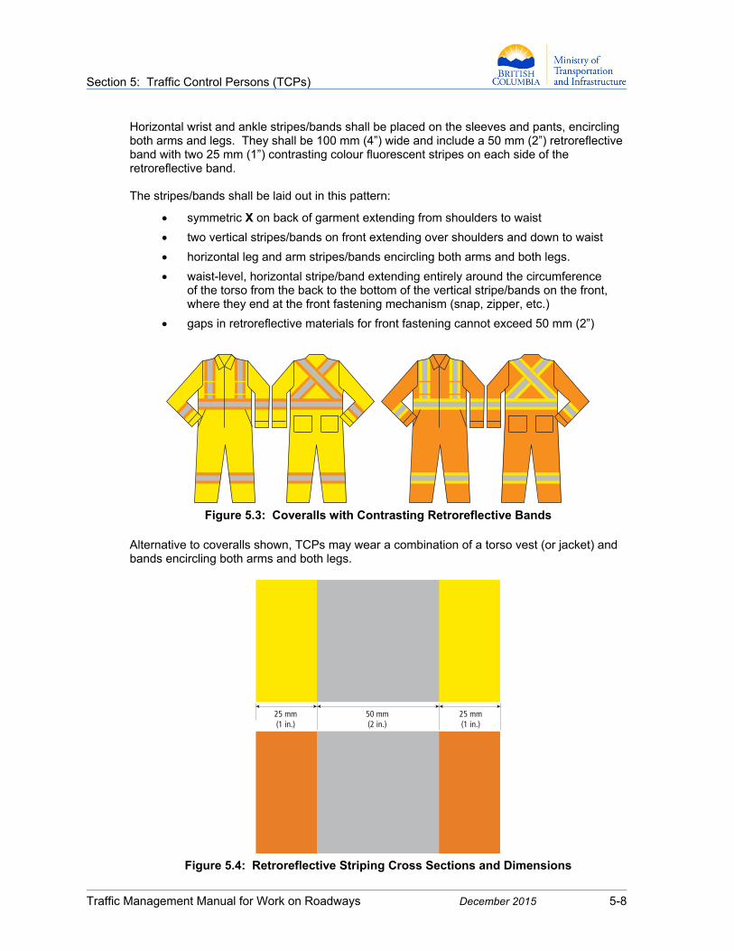
Section 5: Traffic Control Persons (TCPs)
Traffic Management Manual for Work on Roadways December 2015 5-8
Horizontal wrist and ankle stripes/bands shall be placed on the sleeves and pants, encircling both arms and legs. They shall be 100 mm (4”) wide and include a 50 mm (2”) retroreflective band with two 25 mm (1”) contrasting colour fluorescent stripes on each side of the retroreflective band. The stripes/bands shall be laid out in this pattern:
symmetric X on back of garment extending from shoulders to waist
two vertical stripes/bands on front extending over shoulders and down to waist
horizontal leg and arm stripes/bands encircling both arms and both legs.
waist-level, horizontal stripe/band extending entirely around the circumference of the torso from the back to the bottom of the vertical stripe/bands on the front, where they end at the front fastening mechanism (snap, zipper, etc.)
gaps in retroreflective materials for front fastening cannot exceed 50 mm (2”)
Figure 5.3: Coveralls with Contrasting Retroreflective Bands
Alternative to coveralls shown, TCPs may wear a combination of a torso vest (or jacket) and bands encircling both arms and both legs.
Figure 5.4: Retroreflective Striping Cross Sections and Dimensions
25 mm(1 in.)
25 mm(1 in.)
50 mm(2 in.)

Section 5: Traffic Control Persons (TCPs)
Traffic Management Manual for Work on Roadways December 2015 5-9
5.4.3 Apparel for Other Onsite Workers Work zone workers who are not TCPs shall wear Class 2 safety garments that comply with both the CSA Z96-02 standard and the WorkSafeBC requirement. At minimum, Class 2 high-visibility material shall fully cover the upper torso (front, back, sides, and over the shoulders). The following apparel components shall also comply with the retroreflectivity requirements for TCPs (see Section 5.4.2: Apparel Retroreflectivity for TCPs):
fluorescent background material
fluorescent 100 mm (4”) contrasting stripe
50 mm (2”) retroeflective bands of tape
Figure 5.5: Worker Vests with Contrasting Retroreflective Bands (Day-Time Apparel for TCPs)
Note: For work on Provincial roadways, the Ministry adopted standard outlined above for work apparel exceeds WorkSafeBC’s retroreflectivity standard.
This standard provides both adequate retroreflectivity and contrasting colour, and applies to all workers on all Ministry projects.

Section 5: Traffic Control Persons (TCPs)
Traffic Management Manual for Work on Roadways December 2015 5-10
5.4.4 Apparel Labelling for All Onsite Workers Garment labels should include these details to comply with the CAN/CSA Z96-02 standard:
1. Manufacturer or authorized representative name, trademark, or other form of identification.
2. Designation of the product type (i.e., Coverall), commercial name, or code.
3. Size designation.
4. CSA Z96.
5. Apparel Class and Level of Performance for the retroreflective material.
6. Indication that background material is fluorescent.
7. Indication of Flame Resistant (FR) Performance if applicable.
Figure 5.6: Manufacturer’s Label
Section 5: Traffic Control Persons (TCPs)
Traffic Management Manual for Work on Roadways December 2015 5-11
5.5 TCP Communications
5.5.1 Fundamental Principles
TCPs work together to regulate traffic through the work zone. This means that they need to communicate effectively with each other.
When the two TCPs are within sight of each other:
They should use pre-arranged visual signals to communicate.
One TCP should wait until signals are acknowledged by the other TCP before changing traffic flow.
When the two TCPs are not inter-visible, such as on curves or hills, they should either use two-way radios or take the following steps:
1. Station a third TCP between them so that signals can be relayed visually. This third person should stand outside the travel lanes at a location visible to the two other TCPs. This will be practicable only within short work zones.
For illustrations of these positioning requirements, see Figure 5.7: Positioning Requirements When Two TCPs Are Not Inter-Visible.
2. Equip the intermediate TCP with a Stop/Slow paddle for relaying signals from the TCP at one end to the TCP at the other end.
3. Ensure that all three TCPs understand and acknowledge the pre-arranged signals.

Section 5: Traffic Control Persons (TCPs)
Traffic Management Manual for Work on Roadways December 2015 5-12
Figure 5.7: Positioning Requirements When Two TCPs Are Not Inter-Visible
TCP
TCP
WORK AREA
TCP 1
TCP 2
WORK AREA
TCP 3
TCP 2
TCP 3
25 - 35 mWORK AREA
TCP 3
50 - 75 m TCP 2
TCP 1
TCP 1
WORK AREA
25 - 35 m
50 - 75 m
50 - 75 m
25 - 35 m
STRAIGHT ROAD
CURVE
HILL

Section 5: Traffic Control Persons (TCPs)
Traffic Management Manual for Work on Roadways December 2015 5-13
5.5.2 TCP Radios 1. Radio-Based Tasks
Using radios allows TCPs to carry out several important tasks:
communicate with others in areas where they cannot be seen
pass along information about traffic in the queue or passing through the site
advise of movements or encroachment of construction traffic on travelling lanes
smoothly coordinate the movement of public and construction traffic
advise of incidents or issues that may occur on the site
warn of approaching emergency vehicles
coordinate safe passage of construction traffic past the vehicle queue
2. Rules for Radio Use
When using radios, TCPs should follow these rules:
use as specified in the manufacturer’s instructions and conditions of use
ensure that radios work properly across the work zone or work activity area before beginning to use them for traffic control
carry spare batteries and have chargers readily available
use only one ear for a headset or receiver, keeping the other free for hearing other noises in the area
ensure that both hands are free for use
pre-arrange voice signals for every situation, and do not change them
speak clearly
ask for unclear messages to be repeated
avoid unnecessary talk
avoid inappropriate comments
be aware of signal delay and allow time for the transmission to get through
3. Radio Frequencies
It is important to use radio frequencies that allow for communication not only between TCPs but also with the Site Foreman, First Aid Attendant, and equipment operators who may be encroaching on or entering into the travel lanes. It is best to use one common frequency for all onsite personnel. If this is not possible, the Traffic Control Supervisor should carry an additional radio that uses the work site frequency in order to communicate with the work site and help to coordinate movements and pass information to TCPs on their radio frequency.
Section 5: Traffic Control Persons (TCPs)
Traffic Management Manual for Work on Roadways December 2015 5-14
5.6 TCP Positioning and Signals
5.6.1 Hazard and Risk Assessment
When deciding on a position for the TCP and the traffic queue, it is important to identify and assess the potential risks associated with all site hazards. If TCPs and traffic queues will be positioned such that the TCPs are at high risk from a hazard, appropriate steps should be taken to eliminate or minimize the risk. It may be necessary to remove the hazard or reposition the TCP. Hazards that create risk for TCPs include, but are not limited to:
rock fall areas or avalanche zones (seasonal)
blind corners and hill crests
tunnel entrances and exits
lengthy or steep grades
danger trees
wildlife
dark or remote areas
heavy traffic congestion
large commercial or business accesses
Note: TCPs should be able to focus their attention on traffic and not be distracted by having
to watch out for other hazards. The distance between the Traffic Control Person Ahead C-001-1 sign and the TCP should not exceed 150 metres. If there is not an ideal location within this distance because of road features or conditions, an additional sign should be used in advance of the C-001-1, such as a Flagger Ahead C-001-2 sign or a Prepare to Stop C-029 sign.
5.6.2 Positioning Rules for TCPs 1. Stand either on the shoulder adjacent to the traffic being controlled or in a lane that has
been closed to traffic, on the same side of the roadway where you are controlling traffic. Be aware that the closed lane is not the opposing lane, even when controlled by another TCP or device.
Always plan an escape route from every position you assume—i.e., an uninhibited path for avoiding errant vehicles (see also Section 5.7.1: Ability to Make Evasive Manoeuvers).
After more than one vehicle has been stopped—and only if necessary—you may move into the lane under your control to assess queue length or to achieve a better view of approaching vehicles.
Avoid entering a lane being used by opposing traffic.
Return to your starting position before you release the stopped traffic queue.

Section 5: Traffic Control Persons (TCPs)
Traffic Management Manual for Work on Roadways December 2015 5-15
2. Unless otherwise specified, stand 25 to 35 metres from the TCP taper and 50 to 75 metres from the downstream taper to avoid out-of-control vehicles and to provide manoeuvring room for responding to vehicles that make unanticipated lane changes.
3. Face the centre of the road, with your back to the road shoulder, scanning traffic approaching from both directions. Remain aware of what is happening in the stopped lane.
4. Where work is in progress adjacent to an intersection, it may be necessary to stand in the middle of the intersection, in which case it may not be possible to comply with the three rules above.
5. Stand where you can see equipment on the site and where you can see—and be seen by—approaching drivers. To the extent practicable, stand where the background will make you as conspicuous as possible.
6. To be visible to drivers, stand away from the other workers, and never stand in a group of people while stopping traffic.
7. Never use your body as a barrier for blocking errant vehicles.
8. Regardless of the rules listed above, always stand where you can be easily seen by approaching drivers, and in a position that is suitable for safely stopping traffic and/or directing traffic through the work activity area.
5.6.3 Positioning Rules for TCPs in Intersections
1. TCP direction in intersections cannot conflict with the direction provided by any existing intersection control. Traffic signals shall be shut off or changed to flash mode. Stop signs shall be covered.
2. Traffic Control Persons must be visible to approaching traffic and not obscured by advance warning or other signage.
3. It is important to ensure that temporary traffic control devices are consistent with the use of TCPs so that drivers can determine what is expected of them through the intersection.

Section 5: Traffic Control Persons (TCPs)
Traffic Management Manual for Work on Roadways December 2015 5-16
5.6.4 Temporary Stop Bars Temporary stop bars (stop lines) may be used by TCPs to help define a specific stopping location in advance of the TCP position. Temporary stop bars not only provide road users with defined stopping locations but also help TCPs to maintain a safe separation from stopped vehicles. A temporary stop bar must be white, and at least 25 cm (10”) wide. It should extend across the full width of the lane for which it is intended, perpendicular to the direction of vehicular travel. It is made of low-profile plastic or another temporary material that is heavy enough not to be displaced when vehicles stop on it or are driven over it at anticipated speeds. The profile must be low enough that it does not impede traffic flow when being crossed by traffic. One tubular marker should be used on the shoulder side and one on the median side of a temporary stop bar, with each tubular marker displaying the appropriate Stop Line R-025-R or R-025-L sign.
Figure 5.8: Temporary Stop Bar
A temporary stop bar should be placed at least one-half of Distance A from the TCP (Distance A values are those shown for Construction Sign Spacing in Table B – Device Spacing Lengths, see Section 6.6 or Appendix F), with sufficient sight distance provided for approaching drivers. A temporary stop bar should not be placed:
on sharp horizontal or vertical curves
across bicycle lanes
through pedestrian crossings
within intersections that have permanent stop bars
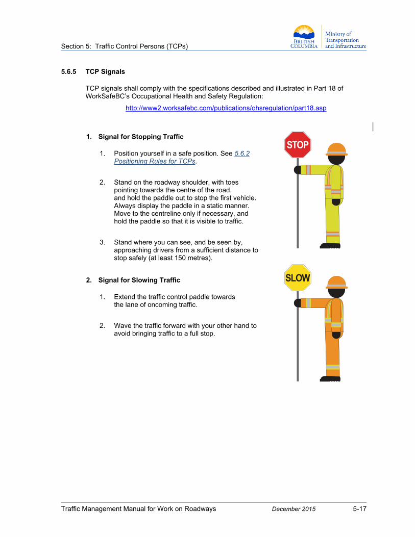
Section 5: Traffic Control Persons (TCPs)
Traffic Management Manual for Work on Roadways December 2015 5-17
5.6.5 TCP Signals TCP signals shall comply with the specifications described and illustrated in Part 18 of WorkSafeBC’s Occupational Health and Safety Regulation:
http://www2.worksafebc.com/publications/ohsregulation/part18.asp
1. Signal for Stopping Traffic
1. Position yourself in a safe position. See 5.6.2
Positioning Rules for TCPs.
2. Stand on the roadway shoulder, with toes pointing towards the centre of the road, and hold the paddle out to stop the first vehicle. Always display the paddle in a static manner. Move to the centreline only if necessary, and hold the paddle so that it is visible to traffic.
3. Stand where you can see, and be seen by, approaching drivers from a sufficient distance to stop safely (at least 150 metres).
2. Signal for Slowing Traffic
1. Extend the traffic control paddle towards
the lane of oncoming traffic.
2. Wave the traffic forward with your other hand to avoid bringing traffic to a full stop.
STOP
SLOW

Section 5: Traffic Control Persons (TCPs)
Traffic Management Manual for Work on Roadways December 2015 5-18
3. Stopping Sight Distances
When slowing and stopping traffic, it is critical to remember the required stopping distances for vehicles travelling at various speeds. The faster a vehicle is moving, the more distance it requires to stop. The size and weight of a vehicle also affect its stopping distance.
Table 5.1: Stopping Sight Distances
Vehicle Speed (km/h)
Stopping Sight Distance
(m) Notes
50 60 These are stopping sight distances (SSD) for passenger vehicles in wet conditions on a level roadway.
More stopping distance is required for larger, heavier vehicles.
More stopping distance is required on a downgrade.
The table values are from the Transportation Association of Canada (TAC) Geometric Design Guide for Canadian Roads (1999), rounded to the nearest 10.
60 80
70 110
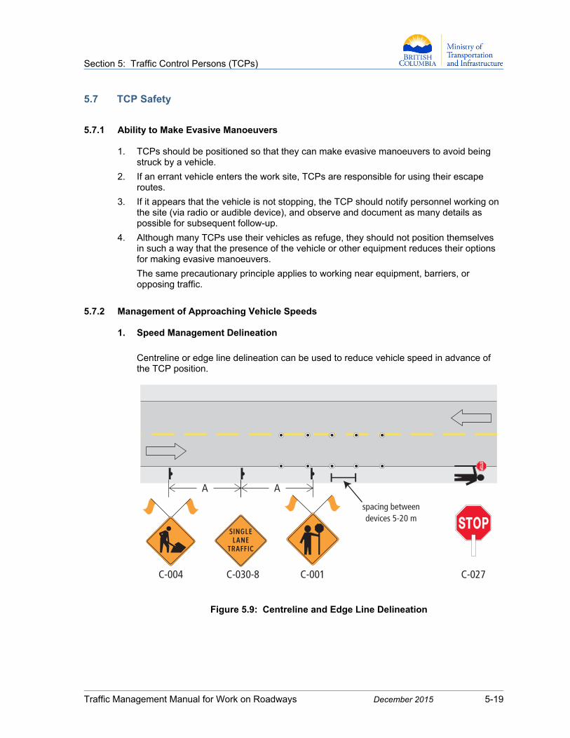
Section 5: Traffic Control Persons (TCPs)
Traffic Management Manual for Work on Roadways December 2015 5-19
5.7 TCP Safety
5.7.1 Ability to Make Evasive Manoeuvers
1. TCPs should be positioned so that they can make evasive manoeuvers to avoid being
struck by a vehicle.
2. If an errant vehicle enters the work site, TCPs are responsible for using their escape routes.
3. If it appears that the vehicle is not stopping, the TCP should notify personnel working on the site (via radio or audible device), and observe and document as many details as possible for subsequent follow-up.
4. Although many TCPs use their vehicles as refuge, they should not position themselves in such a way that the presence of the vehicle or other equipment reduces their options for making evasive manoeuvers.
The same precautionary principle applies to working near equipment, barriers, or opposing traffic.
5.7.2 Management of Approaching Vehicle Speeds
1. Speed Management Delineation
Centreline or edge line delineation can be used to reduce vehicle speed in advance of the TCP position.
Figure 5.9: Centreline and Edge Line Delineation
C-004 C-030-8 C-001 C-027
spacing betweendevices 5-20 m
A A

Section 5: Traffic Control Persons (TCPs)
Traffic Management Manual for Work on Roadways December 2015 5-20
2. Speed Management at Night
When TCPs are working during hours of darkness and are having difficulty getting traffic to stop, various traffic control options may assist with slowing and stopping traffic. Examples include, but are not limited to:
increasing number of advance warning signs and devices
increasing sign sizes
using dynamic messaging signs (DMS)
using speed reader boards
using an oversized STOP R-001 sign (75 cm x 75 cm) on a barricade across the closed lane where the TCP is positioned
5.7.3 Prohibitions for TCPs While Actively Controlling Traffic
1. Never stand near a vehicle or sit in a vehicle when actively controlling traffic.
2. Never argue with a driver.
3. Never stand in an open travelled portion of the roadway while traffic is moving.
4. Never accept an assignment to carry out other onsite work, and never attempt to carry out any other onsite work.
5. Never allow the TCP sign to be displayed when a TCP is not directing traffic.
6. Never give direction that contradicts a traffic signal.
7. Never converse with any person about anything that is not work-related, and ensure that all work-related conversation is both necessary and brief.
8. Never sit when actively controlling traffic.
9. Never lean on a post or other object.
10. Never use a mobile device, tape, disk, MP3 player, TV, non-work radio, or any other device that impairs sight, hearing, or attention. Use cell phones only to communicate about onsite emergencies.
11. Never stand near equipment.
12. Never turn your back on approaching traffic.
13. Never wear clothing or items that can obscure or reduce peripheral vision, such as hoodies, certain kinds of sunglasses, etc.
14. Never become impatient or enraged.
15. Never attempt to slow traffic by displaying the STOP sign rather than the SLOW sign.
16. Never leave the control position without being replaced. Meal, coffee, toilet, and rest breaks should be pre-arranged before work starts.
17. Never regulate traffic if your judgment is impaired in any way.
18. Never regulate traffic if you have suffered a reduction in performance that could increase anyone’s exposure to risk.
Section 5: Traffic Control Persons (TCPs)
Traffic Management Manual for Work on Roadways December 2015 5-21
5.8 Emergency Procedures
5.8.1 Passage of Emergency Vehicles and Personnel
TCPs should review the Traffic Management Plan, which may specify how emergency vehicles and personnel are to be accommodated or taken through the work zone, and should discuss the process to be used in these situations with the Traffic Control Supervisor and Site Supervisor.
TCPs need to be aware of any instructions that should be communicated to the drivers of emergency vehicles, including:
the path to drive
where hazards may exist
any communications required along the way (e.g., the lead vehicle may be given a radio with the site frequency to be returned to the TCP at the other end)
a site map if the work zone is long, such as a repair work zone established to deal with a significant flood event
In smaller rural communities, many emergency service providers are volunteers, which means that the emergency facility is not staffed on a regular basis. In these situations, volunteers may be driving personal vehicles to their “hall” to pick up emergency vehicles.
There should be a process for allowing these volunteers to get to their hall quickly, keeping in mind that they may be passing through the work zone again shortly thereafter with an emergency response vehicle.

Section 5: Traffic Control Persons (TCPs)
Traffic Management Manual for Work on Roadways December 2015 5-22
5.8.2 Traffic Control at Emergency Scenes Members of emergency services and recovery groups that may respond to a motor vehicle incident may include:
police, fire, and ambulance responders
highway rescue and search and rescue responders
towing companies
Road Authority officials
maintenance contractors
other emergency groups
Members of these emergency responder groups often have to control traffic around the site of an emergency or crash. Before implementing traffic control, responders and workers should ensure their own safety and the safety of others.
Having assured the safety of themselves and other onsite personnel, emergency responders are expected to maintain traffic operations through the area impacted by the emergency by employing basic traffic control principles, and to be trained in:
basic traffic control techniques
traffic control equipment setup, operation, and take-down
the traffic management principles outlined in this Manual
the use of a buffer vehicle to protect the workplace
the use of appropriate personal protective clothing and safety equipment
other appropriate safe work procedures
If the traffic control situation will persist for more than two hours, the emergency responders directing traffic are expected to be trained in a manner acceptable to WorkSafeBC for high-risk traffic control or to be replaced by personnel who have this training.