Embed Size (px)
Citation preview

1
372 ROUTE 4 BARRINGTON, NH 03825 USA TEL (603) 868-5720 FAX (603) 868-1040 1-800-435-6708 E-Mail:[email protected] www.seafrost.com
TRADEWINDS AIR/WATER INSTALLATION INSTRUCTIONS
CONDENSING UNIT LOCATION AND MOUNTING The water-cooled option should be considered supplemental cooling. Installation should proceed with a proper air-cooling first. The water-cooling feature should be used to enhance efficiency on occasions when cold-water temperatures are encountered or interior cabin air temperatures are extreme The design of the TRADEWINDS allows placement of the air-cooled unit in an enclosed space such as a cabin locker or sail locker. Allow 1.5 inches of clearance between the back of the unit and any obstruction. Air flows through the condensing unit and out the back. Intake air should be drawn in from the cabin area to insure the coolest, driest air supply. Intake ducting from the exterior of the boat may cause damp salt air to be drawn in which might reduce unit life. This will also increase below deck moisture. Standard 4" duct hose may be used. A vent must be installed in the area to allow warm air to escape.
2
An un-ducted unit in a poorly ventilated small space will heat the air, thereby lowering the capacity of the unit and possibly causing damage by overheating the compressor. Service access and installation requires that the front, top, and left end should be accessible. The duct hose will require 4 inches of clearance past the end of the unit. Mount the TRADEWINDS A/W level. The compressor is at the bottom. The unit may be platform mounted. Holes have been drilled through the bottom of the housing for fastening to a platform. INSTALLATION REQUIREMENTS
• The air inlet should never be blocked.
• Provide for driest, coolest air for intake (top air port on housing.)
• Total combined air duct length should not exceed six feet.
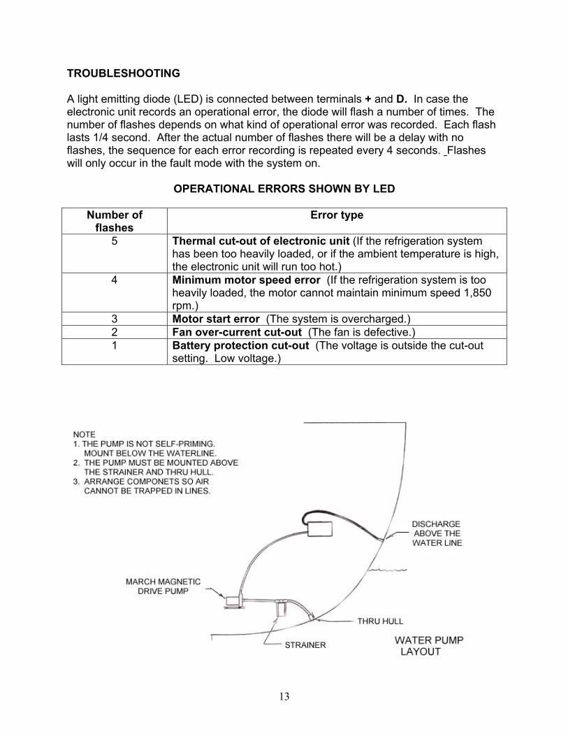
• For intake through a finished panel, order flange grill P/N FG. PUMP INSTALLATION This is a most important operation. Please understand this before beginning the installation. The TRADEWINDS A/W uses a centrifugal pump. It is not self-priming. Air pockets caused by loops or descending lines from one component to the other may cause pump problems. This pump must never be run dry. It is water cooled and lubricated. The wet end may be destroyed if it is started dry. A separate through hull fitting 1/2" or larger should be used. It should be as low in the boat as possible and away from head and cockpit drains. A forward facing scoop will prevent problems if the unit is operating underway. A large seawater strainer should be mounted above the seacock. The pump should be mounted horizontally. It should be higher than the strainer. The discharge should be on the top. The hose should feed up hill to the unit. Refer to the drawing at the end of this manual.

3
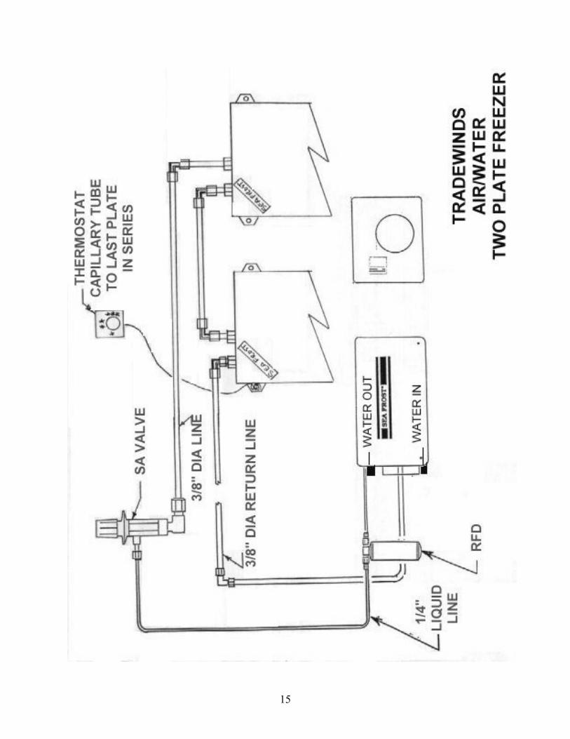
EXPANSION VALVE Connect the expansion valve to either of the 3/8" tubes from the plate. In a two-plate system connect to one of the tubes on one of the plates and connect a jumper between the plates as in the drawing included. Please contact us for advice when connecting to a two-plate system. The valve should be located to allow access to the screw cap on top of the valve. It is preferable that the cap be up. Trim the tube ends on the plate as necessary. However, allow at least 3/4" to insert into the fitting. Refer to the Swagelok installation instructions. The expansion valve can be mounted inside the box or outside. If it is mounted outside it will need to be insulated with cork tape and foam to prevent unwanted sweating and dripping. THE RECEIVER FILTER DRIER (RFD) Unpack and fit the RFD last and at the time of evacuation and charging to prevent saturating the desiccant with moisture. Refer to the "VALVE SCHEMATIC” drawing that follows. Mount the RFD external to the TRADEWINDS cabinet, connecting to the 1/4" liquid line. It must be mounted vertically with the fittings at the top. It is fitted with a sight glass for checking the charge. This glass is best viewed looking straight into the top. Install the RFD in a location that allows proper viewing of the sight glass. The RFD must be installed in the proper flow direction. Connect the tube from the compressor to the in side of the RFD. The out connects to the tube that connects to the valve. RUNNING TUBING LINES The plate and the compressor are connected by two lines. One is 3/8" and the other is 1/4". Run the 1/4" liquid line between the condensing unit area and the expansion valve. This 1/4" line makes up at the expansion valve. The externally mounted receiver filter drier (RFD) will be fitted to this line. (See; "RFD"). The 3/8" line connects to the other plate tube end with a 3/8" fitting. The other end of this 3/8" line connects at the compressor. Run the 1/4" liquid line in contact with 3/8" suction line for at least one foot from the cabinet. Wrap these two tubes tightly together with electrical tape. Insulate this section. This will improve operation and prevent moisture from condensing on the coldest section of these tubes. It is not necessary to insulate the remaining length of 3/8" return line to the compressor.
4
CAP TUBE ENDS Be sure to keep the copper tubing clean and fee of moisture by capping the tubing after each cut with the plastic caps provided. Support the tubing every 18 inches as necessary using tie wraps fastened with self-taping screws. WARNING: The TRADEWINDS unit is shipped with some nitrogen pressure. Before removing the caps on the connection ports remove the plastic caps on the service valve covers and depress the valve cores to vent any existing pressure. COMPRESSOR CONNECTIONS Working one line at a time, remove the Swagelok caps from compressor and condenser fittings. Attach the union fitting bodies. This is a pre-swaged connection. Make up of these pre-swaged connections is 1/4 turn from wrench snug. Connect the 1/4" line to the condenser fitting and 3/8" line to the compressor. Tighten these fittings 1-1/4 turns from wrench snug. NOTES ON SWAGELOK FITTINGS Swagelok fittings come to you completely assembled, finger-tight. (Pieces a, b, and c in Drawing #1 are already together). They are ready for immediate use. Disassembly before use can result in dirt and foreign material getting into the fitting and causing leaks and you risk damaging the threads if nuts are removed. If disassembly is necessary, reassemble per drawing. This is a double ferrule system. The most serious installation problem encountered with SEA FROST is the improper assembly of these fittings. Be sure that you assemble all fittings as in Drawing #1. To ease assembly slacken the fitting nut slightly before assembly. Then retighten with fingers before tightening with a wrench. (This is to avoid cross threading.) Step 1. Always leave two inches of straight, undistorted tubing leading to all Swagelok fittings to allow proper connection. Step 2. Prior to inserting 1/2" tubing into the Swagelok tube fitting, make a pencil mark 1" from end of tube. Prior to inserting 3/8" tubing, make a pencil mark 3/4" from the end of the tube. With 1/4" tubing make a mark 5/8" from the end.
5
Step 3. Insert clean, smooth tubing with the pencil mark into the Swagelok tube fitting. You can be sure the tube is resting firmly on the shoulder of the fitting when the pencil mark is flush with the nut. This mark will also indicate that the tube has not moved before tightening. (As the fitting is tightened the space from the pencil mark to the shoulder will increase.) Step 4. Tighten the Swagelok nut to a wrench snug* position. Scribe the nut with a pencil at the 6:00 o'clock position (see drawing #1, step # 2). * Wrench snug is the first point in the assembly tightening when the tube cannot be pulled from the fitting, (i.e. when the ferrules tighten enough to contact the tubing). Step 5. Now, while holding the fitting body with a back-up wrench, tighten the nut one-and-one-quarter turns ( 1-1/4). To do so, watch the scribe mark, make one complete revolution, and continue to the 9:00 o'clock position. (See drawing #1, step #3).

6
DRAWING 1
STEP 1 Simply insert the tubing into the SWAGELOK tube fitting. Make sure that the tubing rest firmly on the shoulder of the fitting and that the nut is wrench snug.
STEP 2 Before tightening the SWAGELOK nut, scribe the nut at the six o'clock position.
STEP 3 Now, while holding the fitting body steady with a backup wrench, tighten the nut 1 1/4 turns. Watch the scribe mark, make one complete revolution and continue to the 9 o'clock position. By scribing the nut at the 6 o'clock position as it appears to you, there will be no doubt as to the starting position. When tightened 1 1/4 turns to the 9 o'clock position, you can easily see that the fitting has been properly installed.
7
SWAGELOK FITTINGS ARE TO BE TIGHTENED TO A TORQUE SPEC, NOT INFINITE TIGHTNESS. BE SURE YOUR STARTING POINT IS WRENCH SNUG. A DISTORTED TUBE MIGHT GIVE A FALSE STARTING POINT. * When making all connections, USE TWO WRENCHES. Don't allow the fittings to turn or twist when tightening. RECONNECTING PRE-SWAGED FITTINGS
Connections can be disconnected and retightened many times. When reconnecting, insert the tubing with pre-swaged ferrules into the fitting until the front ferrule seats in the fitting. Tighten the nut by hand. After tightening to wrench snug, rotate the nut about one-quarter turn with a wrench. SWAGELOK PERFORMANCE
Swagelok fittings have built-in spring interaction between the ferrules. This compensates for temperature changes and allows the fittings to be reconnected many times. As the fitting is tightened, a burnishing occurs between the body of the fitting and the ferrules and between the ferrules and the tube. This action provides the tightest connection available.
8
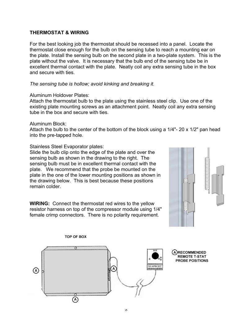
THERMOSTAT & WIRING For the best looking job the thermostat should be recessed into a panel. Locate the thermostat close enough for the bulb on the sensing tube to reach a mounting ear on the plate. Install the sensing bulb on the second plate in a two-plate system. This is the plate without the valve. It is necessary that the bulb end of the sensing tube be in excellent thermal contact with the plate. Neatly coil any extra sensing tube in the box and secure with ties. The sensing tube is hollow; avoid kinking and breaking it. Aluminum Holdover Plates: Attach the thermostat bulb to the plate using the stainless steel clip. Use one of the existing plate mounting screws as an attachment point. Neatly coil any extra sensing tube in the box and secure with ties. Aluminum Block: Attach the bulb to the center of the bottom of the block using a 1/4"- 20 x 1/2" pan head into the pre-tapped hole. Stainless Steel Evaporator plates: Slide the bulb clip onto the edge of the plate and over the sensing bulb as shown in the drawing to the right. The sensing bulb must be in excellent thermal contact with the plate. We recommend that the probe be mounted on the plate in the one of the lower mounting positions as shown in the drawing below. This is best because these positions remain colder. WIRING: Connect the thermostat red wires to the yellow resistor harness on top of the compressor module using 1/4" female crimp connectors. There is no polarity requirement.
9
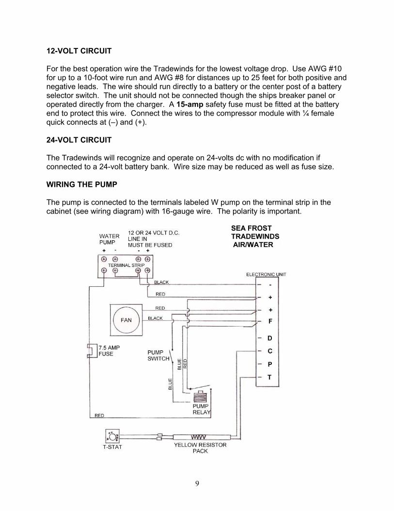
12-VOLT CIRCUIT For the best operation wire the Tradewinds for the lowest voltage drop. Use AWG #10 for up to a 10-foot wire run and AWG #8 for distances up to 25 feet for both positive and negative leads. The wire should run directly to a battery or the center post of a battery selector switch. The unit should not be connected though the ships breaker panel or operated directly from the charger. A 15-amp safety fuse must be fitted at the battery end to protect this wire. Connect the wires to the compressor module with ¼ female quick connects at (–) and (+). 24-VOLT CIRCUIT The Tradewinds will recognize and operate on 24-volts dc with no modification if connected to a 24-volt battery bank. Wire size may be reduced as well as fuse size. WIRING THE PUMP The pump is connected to the terminals labeled W pump on the terminal strip in the cabinet (see wiring diagram) with 16-gauge wire. The polarity is important.
10
COMMISSIONING Attach clean, purged R-134a gauges to the suction service port on compressor. This is the blue-capped tube stub on the compressor. It is not necessary to connect to the high-pressure port when starting a new system. This is provided to aid in fault diagnosis. Pressurize with nitrogen or R-134a only. Check for leaks. After checking for leaks, evacuate. Pump down to the best vacuum.
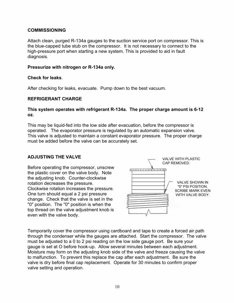
REFRIGERANT CHARGE This system operates with refrigerant R-134a. The proper charge amount is 6-12 oz. This may be liquid-fed into the low side after evacuation, before the compressor is operated. The evaporator pressure is regulated by an automatic expansion valve. This valve is adjusted to maintain a constant evaporator pressure. The proper charge must be added before the valve can be accurately set. ADJUSTING THE VALVE Before operating the compressor, unscrew the plastic cover on the valve body. Note the adjusting knob. Counter-clockwise rotation decreases the pressure. Clockwise rotation increases the pressure. One turn should equal a 2 psi pressure change. Check that the valve is set in the "0" position. The "0" position is when the top thread on the valve adjustment knob is even with the valve body. Temporarily cover the compressor using cardboard and tape to create a forced air path through the condenser while the gauges are attached. Start the compressor. The valve must be adjusted to a 0 to 2 psi reading on the low side gauge port. Be sure your gauge is set at O before hook-up. Allow several minutes between each adjustment. Moisture may form on the adjusting knob side of the valve and freeze causing the valve to malfunction. To prevent this replace the cap after each adjustment. Be sure the valve is dry before final cap replacement. Operate for 30 minutes to confirm proper valve setting and operation.

11
The valve may need to be cleared of dirt or chips if adjustment is not possible. With the compressor running, turn the valve adjustment knob clockwise about 3 turns momentarily then back to the proper setting. Do not leave the valve in open position (allowing high backpressure) as this may cause the compressor to overload. After satisfactory adjustment, turn off the thermostat. Remove the gauges. Recap the service ports. Replace the service panel. When the valve has dried, insulate the valve body by cutting the insulating sleeve to fit the valve then wrap it with cork tape. This is to prevent condensation. Also insulate the one-foot section of 3/8" tubing that exits the cabinet. (The valve need not be insulated if the valve is in the icebox).
Trouble shooting note: The operating pressure of the system will not indicate the amount of refrigerant in the system. The valve will not give proper operation or pressure if it is undercharged. Check the valve scribe line. It should correlate to gauge pressure. The system requires enough refrigerant to supply liquid to the valve. If the valve has a steady hissing sound then the charge is ok. If the valve is sputtering then it is low. If the valve is making a noticeable roar it is empty. If the low side pressure is properly set the high side pressure will be 80 to 135 psi depending on the air temperature (50 to 95 degrees F.) through the unit. Almost immediately upon start up the valve body will begin to frost. THE THERMOSTAT The TRADEWINDS A/W thermostat is variable. Turning the knob fully counterclockwise turns the unit "OFF". The fully clockwise setting is the coldest. The thermostat may be adjusted to obtain any temperature desired in the cabinet. The thermostat may be calibrated should the warmest setting be too cold. OPERATION DESCRIPTION The SEA FROST TRADEWINDS A/W is a small system. It is efficient in its electrical conversion of energy to heat movement. Its rate of cooling is 1/20 the rate of the Engine Drive system. By being small it is quiet, compact, has low electrical starting requirements and running power draw, and is able to be air or water-cooled. With the control switch (mounted on the left end of the cabinet) down the unit is operating as an air-cooled system. With the switch in the up position the unit will operate as an air/ water-cooled unit. The pump will switch on and off with the compressor and fan. NOTE: The water pump has a limited brush life. It is best to select water-cooling only when on board and operating from battery power.
12
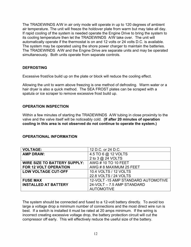
The TRADEWINDS A/W in air only mode will operate in up to 120 degrees of ambient air temperature. The unit will freeze the holdover plate from warm but may take all day. If rapid cooling of the system is needed operate the Engine Drive to bring the system to its cooling temperature then let the TRADEWINDS A/W take over. The unit will automatically operate if the thermostat is on and 12 volts or 24 volts D.C. is available. The system may be operated using the shore power charger to maintain the batteries. The TRADEWINDS A/W and the Engine Drive are separate units and may be operated simultaneously. Both units operate from separate controls. DEFROSTING Excessive frost/ice build up on the plate or block will reduce the cooling effect. Allowing the unit to warm above freezing is one method of defrosting. Warm water or a hair dryer is also a quick method. The SEA FROST plates can be scraped with a spatula or ice scraper to remove excessive frost build up. OPERATION INSPECTION Within a few minutes of starting the TRADEWINDS A/W tubing in close proximity to the valve and the valve itself will be noticeably cold. (If after 20 minutes of operation cooling in this area is not observed do not continue to operate the system.) OPERATIONAL INFORMATION VOLTAGE: 12 D.C. or 24 D.C. AMP DRAW: 4.5 TO 6 @ 12 VOLTS
2 to 3 @ 24 VOLTS WIRE SIZE TO BATTERY SUPPLY: FOR 12 VOLT OPERATION
AWG # 10 TO 10 FEET AWG # 8 MAXIMUM 25 FEET
LOW VOLTAGE CUT-OFF 10.4 VOLTS / 12 VOLTS 22.8 VOLTS / 24 VOLTS
FUSE MAX INSTALLED AT BATTERY
12-VOLT -15 AMP STANDARD AUTOMOTIVE 24-VOLT – 7.5 AMP STANDARD AUTOMOTIVE
The system should be connected and fused to a 12-volt battery directly. To avoid too large a voltage drop a minimum number of connections and the most direct wire run is best. If a switch is installed it must be rated at 20 amps minimum. If the wiring is incorrect creating excessive voltage drop, the battery protection circuit will cut the compressor off early. This will effectively reduce the useful size of the battery.
13
TROUBLESHOOTING A light emitting diode (LED) is connected between terminals + and D. In case the electronic unit records an operational error, the diode will flash a number of times. The number of flashes depends on what kind of operational error was recorded. Each flash lasts 1/4 second. After the actual number of flashes there will be a delay with no flashes, the sequence for each error recording is repeated every 4 seconds. Flashes will only occur in the fault mode with the system on.
OPERATIONAL ERRORS SHOWN BY LED
Number of flashes
Error type
5 Thermal cut-out of electronic unit (If the refrigeration system has been too heavily loaded, or if the ambient temperature is high, the electronic unit will run too hot.)
4 Minimum motor speed error (If the refrigeration system is too heavily loaded, the motor cannot maintain minimum speed 1,850 rpm.)
3 Motor start error (The system is overcharged.) 2 Fan over-current cut-out (The fan is defective.) 1 Battery protection cut-out (The voltage is outside the cut-out
setting. Low voltage.)

14
15
16
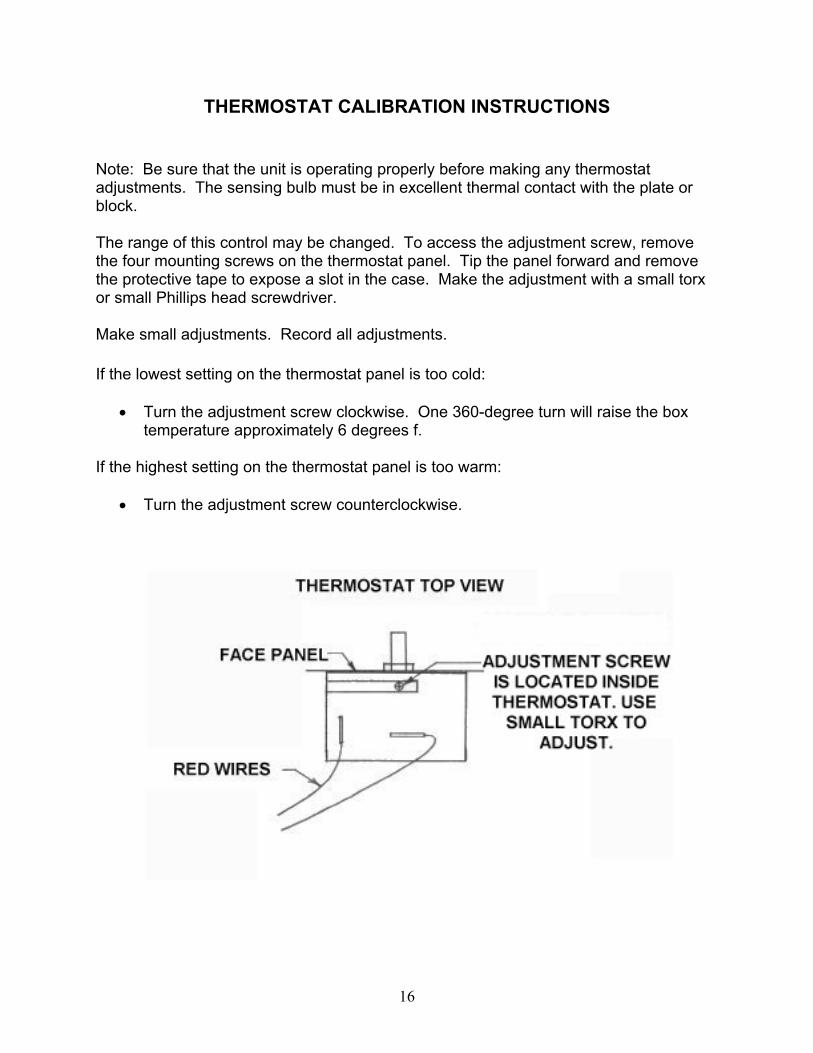
THERMOSTAT CALIBRATION INSTRUCTIONS
Note: Be sure that the unit is operating properly before making any thermostat adjustments. The sensing bulb must be in excellent thermal contact with the plate or block. The range of this control may be changed. To access the adjustment screw, remove the four mounting screws on the thermostat panel. Tip the panel forward and remove the protective tape to expose a slot in the case. Make the adjustment with a small torx or small Phillips head screwdriver. Make small adjustments. Record all adjustments.
If the lowest setting on the thermostat panel is too cold:
• Turn the adjustment screw clockwise. One 360-degree turn will raise the box temperature approximately 6 degrees f.
If the highest setting on the thermostat panel is too warm:
• Turn the adjustment screw counterclockwise.