Embed Size (px)
Citation preview

AGIRA/ELY
PROFESSIONAL A-WHEELTRACTORS (G SERIES)OPERATOR'S MANUAL
PART NO: 41853, 41871, 4187641966, 41974,42149
FORM NO:42639 (11-86) PRINTED IN USA
NOTE
Read this manual carefull-y and
your tractor before using it.
To keep the warranty, the tractoroperated as directed in this manual.
learn to operate and service
must be maintained and
All references to nleft-siden, nright-siden,nbackn are given f rom the operatorts positj.on.
nfrontn, and
Use the serial numbers to ensure prompt and correct servicewhen ordering parts, requesting service r ot making inquiries.
TRACTOR
ENGINE
ENGINE SPEC NUI,IBER
SERIAL NUMBER
SERIAL NUMBER
Look for thisprecautions.YOUR SAFETY IS
symbol to point out important safetyIt meAns -- ATTENTION! BECOII,IE ALERT!INVOLVED.

CONTENTS
1. INSTRUCTIONS FOR SAFE OPERATION
2. CONTROLS
3. OPERATING INSTRUCTIONS
4. SERVICE INSTRUCTIONS
5. STORAGE
6. PROBLEM SOLVING
.I . SPECIFICATIONS AND WIRING
8. SET-UP INSTRUCTIONS
9. WARRANTY
SECTION 1
Instructions for Safe Operation
rmproper use of this tractor can injure people and damage theequipment. People using or servicing this Lractor must reid andfollow the instructions in this manual.It is irnportant to understand that this manual and any otherGravely instruction manuals do not cover every possible danger.It is impossible for Gravely to know of all possiUfe dangeri in<lperating and servicing the tractor and attachments.The purchaser must give these instructions to the people opera-ting and niaintaining this tractor. These people musl use eya andfoot protection.
1"1 Preparation1. Read the tract.cr
caref ulJ-y.ancj atL.achment operatorrs manuais
1
3.
4.
Learn the -ocat -onatLachment c*ntrols -
Learn how ru useatr-achment.
and function of
ihc control-s to stop
all tractor and
the t ract.or anci
very flammable.away frorn fJ,arnesfuel tank whii-espilled gasoline
and interl-ockK
Use caution with gasoline" Gasol-ine isKeep it in a clran and tight containeror hot items. Never put gasol:ne in thethe engine is running or hot. C1ean upbefore startlng engine,Be certain that ait shields, guards,switches are in the correct positions.
6. when hauling the tractor, connect the chassis and rearhitch to the transporting vehicle. Never connect fromcontrol Ievers, rods 1 or like items that couLd bedamaged.

L.2 Operation1. wear foot and eye protection. Do not wear looseclothing.2. Do not use the tractor in the dark without adequate
1 ighting.3, Keep the tractor in good condition. Maintain it as
directed in this manual.4. Replace all parts that becorne damaged or }ost.5. USE ONLY GRAVELY ACCESSORIES AND ATTACHMENTS OR ATTACH-
I'IENTS GRAVELY HAS APPROVED FOR USE WITH THIS TRACTOR.
6. Do not overspeed the engine. Do not override thegovernor.
7. Keep away from moving parls.8. Keep people and animals away from the operating area.9" Do not let people other than the operator ride on the
suJ-ky.
10, Use a slow speed and engage the direction control leverslowly when operating on slopes.
11. Look for and keep away from hazards.12. Before starting the engine, put the direction controllever in the nNEUTRAL" position and the PTO control in
the ,OFF" position.13. Look behind when operating in reverse.1"4. After hitting an object with the tracLor or attachment,
stop the engine and check for damage. Repair any damagebefore continuing operation.
15. Operate the tractor only fron the operatorrs position,on the seat.
16. Travel up and down slopes.I7 . Never permit children to operate the tractor.18. Before leaving the tractor, move the PTO control tonOFFn, lock the brake or put in gear and engage thedirection control leverr and remove the ignition key.
19. rf there is a sudden change in the sound or vibration ofthe tractor or attachmeits, stop the "rrfirr"-ino checkfor damage. Repair any 'damagl or fairure beforecontinuing operation.20. Never ryn the engine indoors except to moveExhaust fumes are dangerous.2I. Go slow on slick surfaces.22. Follow traffic raws when operating on or near23. Before making_ adjustments or servicing, moverOFFnf turn the ignition switch to noFF;, andall moving parts completely stop.
it outside.
a road.the PTO towait until
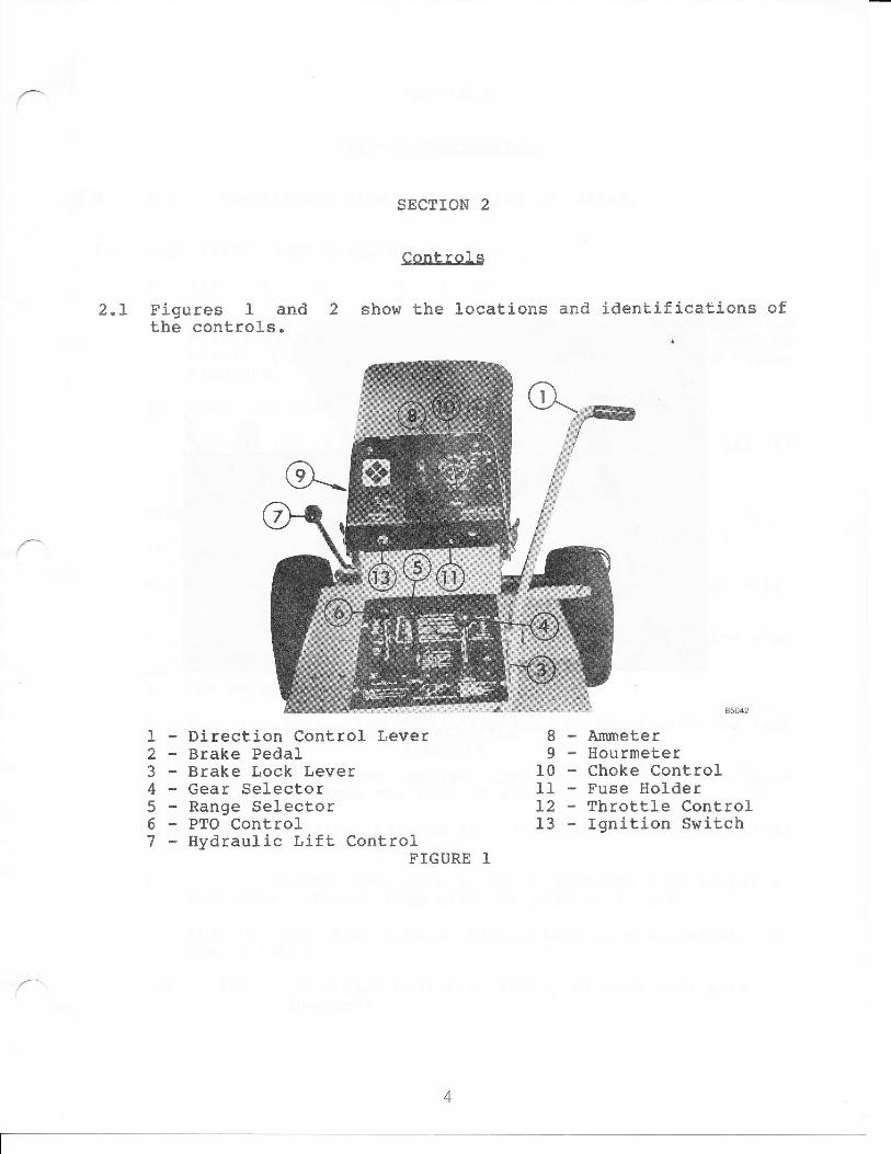
2.I Figures 1 and 2the controls.
SECTION 2
Controls
show the locations and identifications of
I234567
Direction Control LeverBrake PedalBrake Lock LeverGear SelectorRange SelectorPTO ControlHydraulic Lift, Control
FIGURE 1
AmmeterHourmeterChoke ControlFuse HolderThrottl-e ControlIgnition Switch
89-1011L213

I23-
Manual Lift LeverRelease ButtonLift Range Control
FIGURE 2
5
SECTION 3
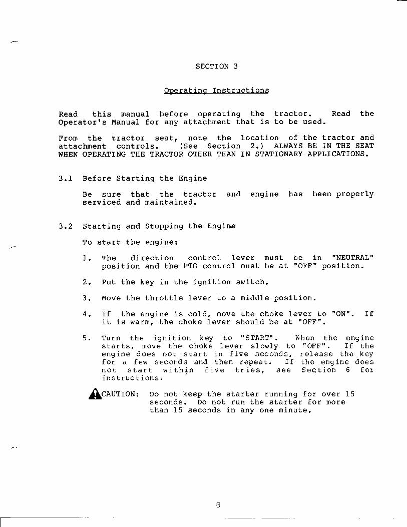
Operating Instructions
Read this manuaL before operating the tractor. Read theOperator's Manual- for any attachment that is to be used.
From the tractor seat, note the location of the tractor andattachment controls. (See Section 2.) ALWAYS BE IN THE SEALWHEN OPERATING THE TRACTOR OTHER THAN IN STATIONARY APPLICATIONS.
3.1 Before Starting the Engine
Be sure that the tractor and engine has been properlyserviced and maintained.
3.2 Starting and Stopping the Engine
To start the engine:1. The direction control lever must be in 'NEUTRAL'position and the PTO control must be at 'OFF" position.2. Put the key in the ignition switch.3. l"love the throttle lever to a middle position.4. If the engine is cold, move the choke lever to nONn. If
it is warm, the choke lever should be at rrOFFn.
5. Turn the ignition key to " START'' . When the eng inestarts, move the choke lever s1ow1y to "oFF". rf theengine does not start in five seconds, release the keyfor a few seconds and then repeat. If the engine doesnot start within five tries, see Section 6 forinstructions.CAUTION: Do not keep the
seconds. Do notthan 15 seconds
starter running for over 15run the startet for morein any one minute.
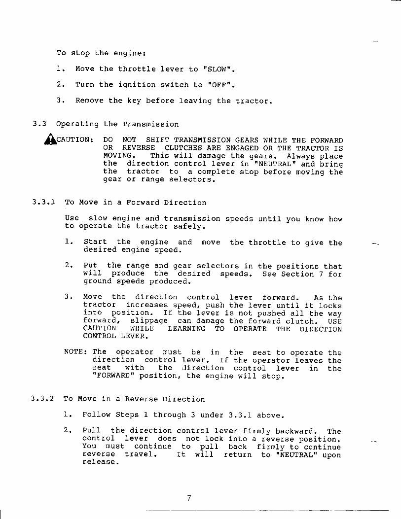
To stop the engine:1. Move the throttle lever to I'SLOW'.
2. Turn the ignition switch to nOFFn.
3. Remove the key before l-eaving the tractor.
3.3 Operating the Transmission
[ceurron, Do Nor sHrFT TRANsMrssroN GEARS wHrLE THE FoRwARDOR REVERSE CLUTCHES ARE ENGAGED OR THE TRACTOR ISMOVING. This will damage the gears. Always placethe direction control lever in 'NEUTRALn and bringthe tractor to a complete stop before moving thegear or range selectors.
3.3.1 To Move in a Forward DirectionUse slow engine and transmission speeds until you know howto operate the tractor safely.1. start the engine and move the throttle to give thedesired engine speed.2. Fut the range and gear sel-ectors in the positions thatwill produce Lhe desired speeds. See Section 7 forgnound speeds produced.3. Move the direction control lever forward. As thetractor increases speed, push the lever untir it. locksinto position. ff; the lever is not pushed all the wayforwandr slippage can damage the f,orward clutch. USECAUTION WHILE I,EARNING TO OPERATE TTIE DIRECTION
CONTROL I,EVER.
NOTE: The operator must be in Lhe seat to operat.e thedirection control lever. If the operator leaves theseat with the ili rection control- lever in thenFORWARDn position, the engine will- stop,
3.3,2 To Move in a Reverse oirection1. FolLow Steps 1 throuEh 3 under 3.3.1 above.2. Pull the direction control lever firnly backward. ThecontroL lever does not lock into a reverse position.You must continue lo pull back firmly to continuereverse travel.
release.It will return to rNEUTRALr upon
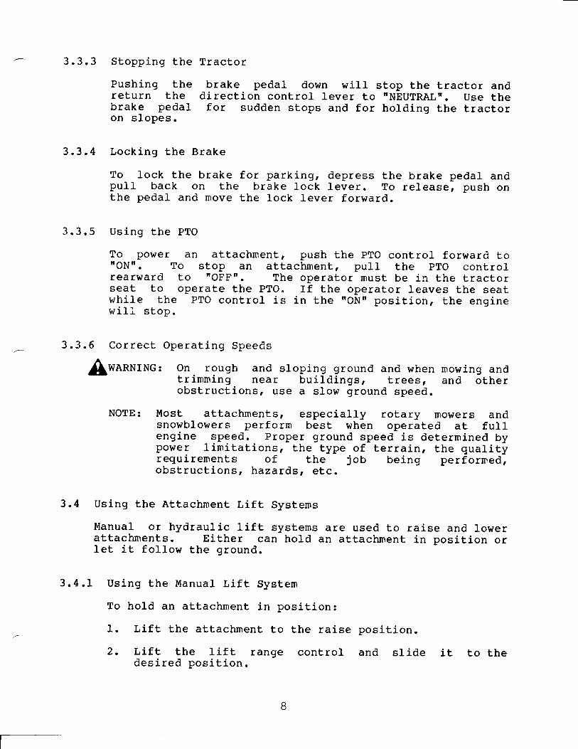
3.3,3 Stopping thePushing thereturn thebrake pedalon slopes.
Tractorbrake pedal down will stop the tractor anddirection control- lever to nNEUTRALn. Use thefor sudden stops and for holding the tractor
3.3.4 Locking the BrakeTo lock the brake for parking, depress the brake pedal andpull back on the brake lock Jever. To reJease, push onthe pedal and move the lock lever forward.
3.3.5 Using the PTO
To power an attachment, push the PTO control forward to'ONn. To stop an attachmenL, pulI the pTO controLrearward to "OFF n. The operator must be in the tractorseat to operate the PTO. If the operator leaves the seatwhile the PTO control is in the nON[ position, the enginewili stop.
3.3.6 Correct Operating Speeds
On rough and sloping ground and when mowing andtrimming near buildings, trees, and otherobstructionsl us€ d slow ground speed.[wanurnc,
NOTE: Ivlost attachments, especially rotary mowers andsnowblowers perform best when operated at fullengine speed. Proper ground speed is determined bypower limitations, the type of terrain, the qualityrequirements of the job being performed,obstructions, hazards, etc.
3.4 Using the Attachment Lift Systems
Manual or hydraulic lift systems are used to raise and lowerattachments. Either can hold an attachment in position orlet it folIow the ground.
3.4.I Using the Manual Lift System
To hold an attachment in position:I. Lift the attachment to the raise position.
and slide2. Lift the lift rangedesired position.
8
cont rol it to the
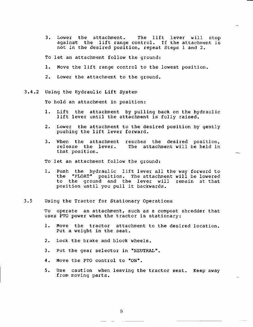
3, Lower the attachment. The Iift lever will stopagainst the lift range controL. ff the attachment isnot in the desired position, repeat Steps I and 2.To let an attachment follow the ground:1. Move the lift range control to the lowest position.2. Lower the attachment to the ground.
3.4.2 Using the Hydraulic Lift. System
To hold an attachment in position:I. Lift the attachnent by pulling back on the hydrauliclift Jever until the attachment is fully raised.2. Lower the attachment to the desired position by gently
pushing the lift lever forward.3. When the attachment reaches the desired position,release the lever. The attachment will be held inthat position.To 1et an attachment follow the ground:1. Push the hydraulic lift lever all the way forward tothe I'FLOATn position. The attachment will be loweredto the ground and the lever wil] remain at thatposition until you pul1 it backwards.
3.5 Using the Tractor for Stationary OperationsTo operate an attachment, such as a compost shredder thatuses PTO power when the tractor is stationary:1. Move the tractor attachment to the desired location.
Put a weight in the seat.2. Lock the brake and block wheels.3. Put the gear selector in 'liEUTRALn.4. Move the PTO control to nON'.
5. Use caution when leaving the tractor seat. Keep awayfrom moving parts.
I

Chart I showsperformed on a
SECTION 4
Service Instructions
the recommended schedule for service that should beregular basis.
SERVICE PERFORI\,IEDI TrtlE TNTERVALSI BETWEEN SERVICE
Chcc3.- Batt-ery.- Fluid (sect ion 4 .5 ) | L I LtiiShqs&ilaLgsx's---iAesui,ss"- ,*51'-- * -_L-*L.**--*"!*=X-rll(;he=k*;hfu--I-n-takc* -r5-cLses**L$-e"sLt-4.{r-9"-i_L-*-.*--*'1-.".-"*&**L.*-_--- t . -trlehee&"*Ci: o-}j ns-S&*sLem.lgc-atj:an* 4-*S-i**-_-**+-----*-:*l**-e-"r-.- *
illeheekMiqn*€""*3i .*J*8"1-."---l-*ttlCtreeil--Es-ansiei$s:i=-an- oi-t*[Ss$ti-E:r* 4 ^ LL) -.*-i J**-e -i. *"- ,"tlCheck Ti re Sressur e -l5es-Li-aa"J-1**- tlxl
CIIART 1
4.I Filling the Fuel- Tanls
$rwo*Nt^c, Gasoline is very flammable. Follow saf etyinstructions shown in Section 1.
Gasoline is added as required. Use clean leadregular grade gasoline. To add gasoline:I. Put the tractor in an open area.2, Stop the engine and lock the brake.3. Clean the fuel cap area.4. Remove the fuel tank cap.
free or
5. FiII the tank with gasoline. Use caution. Do notoverflow "
6 " Rcir:sLail- f uel. ';ank cap"
7 * If qanoJ-ini: is sg>iltredr wipe i: up"
i0

4.2
4.4
General LubricationThere are seven grease fittings to be greasedintervals. Clean the fittings before attachinggun. Use a multi-purpose grease. Add greaseappears at the ends of the bearings. The locatiseven fittings are:1. On the direction control lever.
at 25-hourthe grease
until itons of the
atOn2.3.4.
the front axlethe front axle
each king pin.shown in Figure 3.On
Appty motor oi1areas where slidand I ift control
as
On the steering mechanism as shown in Figure 4.
to all pining occurs insystems every
connections, pivot points andthe clutch, transmission, PTO,25 hours.
4.3 Checking the Engine Oi1
Check the eng ine oil leve1 daily . Never operate t 1,e' eng inewith the oi1 leveI below the Jow niark on the di6;stick. Seey our eng ine nranual for oil spec if ications and oil f ilterservice instructions.To check the oil level:
Clean around the dipstick to prevent dirt fron, enteringthe tube.
1.
3,
4.
6.5.
Remove the dipstick and wipe off the oil.Put the dipstick back in p1ace. Be sure it js all theway down.
Remove the dipstick again and note oil level.Add oil, if needed. Do not overfill.Repeat Step 3.
Chang ing the1. Read your2. Move the
Eng ine Oileng ine rnanual f or
tractor to a 1evel3. If the engine is cold, fet
is warm,
r ecornmended change scheduf e.
area. Lock the brake.it run f or 5 nrinutes.
When the eng inefender.
stop it and r a.ise the rear
Fngine rnuffler and other parts are hot.
4.
11
VIARNlNG:

I - Grease Fitting on the Front AxIeFIGURE 3
45
1-2-3-Grease Fittings forGrease Fittings forAdjusting Bolt
the Steeringlhe Steering
FIGURE
ArmsColumns
4
Lock NutAdjusting Nut
12
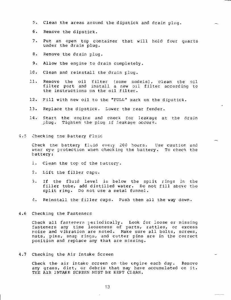
5. Clean the areas around the dipstick and drain plug"6. Remove the dipstick.7. Put an open top container that will hold four quarts
under the drain plug.B. Remove the drain p1ug.
9. Allow the engine to drain completely.i0, Clean and reinstall the drain plug"11. Remove the oil tilter (some nodels), clean the cilfilter port and install a new cil filter according tothe instructions on the oil filter.\2. F' ill with new oil- to the "FULL" mark on t.he d ipstick.13. Replace the dipstick. Lower the rear fender.-.:-4" Start the engine and check f,or ieakage a.t the Crain
FIug , Tighten the plug if leakaoe occurs.
4,5 Checking the BaLtery Fiu:cCheck the battery f 1u j.d every 200 hours " Use caution andwear eye prot.ection when check ing the baLtery. To check tLrebattery:i"" Clean the top of the "hattetry.
2" Lift the f itrler cap$"
3, If the fl"uid level is below the split rinEs in thef i1ler tube, ddd d i still-ed water . Do not f i11 above tiLespl it r ing . Do not use a metal f unnel- .
4. Reinstall the filler caps. Push them all the way down.
4,6 Checking the FastenersCheck all- f asteners l,er iooically. Look f or ioose or missingfasteners any time looseness of parts, rattles, or excessnoise and vibration are noted. Make sure all bolts, screws,nuts, pins, snap rings, and cotter pins are in the correctposition and replace any that are missing.
4.7 Checking the Air fntake Screen
Check the air intake screen on the engine each day. Removeany grass, dirt, or debris that may have accumul-ated on it.THE AIR INTAKE SCREEN IUUST BE KEPT CLEAN.
13

4"8 CheckinE the Cooling Systern
Check the cooJ- inE systern f c'r signs c'f tire collection ofgrass and debris in ttre engine cooling f,ins every 25 hoursor more often when operated in dirty conditions. See yourengine nanua,l for irrstructions'
4"9 Checking the Air CleanerCtreck the air cleaner each day. See your engine manual fotinsi:ructions.
4.10 Changing the Air Cleaner Element
Replace the air cleaner el-er,ent at the correct intervals '5ee your eng ine rnanual- f or instructions.
4.11 Checking the Transmission OilCheck the transmission oil leve1 every 25 hours. If leakagej s observed, check nrotre frequently . The f i11 tube andcheck plug are shown in Figure 5. To check the transmissionoil Jevel:1. Move the tractor to a 1evel area. Stop the engine and
lock the brake.2. Raise the rear fender.3. Clean the check plug and remove it.4. The oil level is correct when oil is at the bottom of
the hole.5. If the level is correct, reinstall and tighten the plug.
If the level is low, add oil. See Section 7 forrecommended lubr icant specif ications.
To add oi1:l. Remove the fill tube cap.
2. Add oit until it reaches the bottom of the check plugho1e.
3. Reinstall and tighten the fitl tube cap and check plug.
14
86025
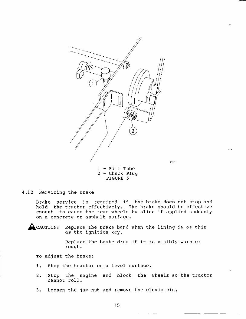
1 - FilI Tube2 - Check Plug
FIGURE 5
4.I2 Servicing the Brake
Brake service is required if the brake does not stop andhold the tractor effectively. The brake should be effectiveenough to cause the rear wheels to slide it applied suddenlyon a concrete or asphalt surface.
[ceurron, Replace the brake banci when the lining' is as thinas the ignition key.
Replace the brake drum if it is visibly worn orrough.
To adjust the brake;1. Stop the tractor on a level surface.2. Stop the engine and block the wheels so the tractor
cannot roll.3. Loosen the jam nut and remove the clevis pin.
15

5.
Turn the clevis clockwise to tighten or counterclockwiseto loosen as needed.
To check the adjustnent, reconnect the clevis and brakeband with the pin.Push the direction control- Iever a1l the way forward.Push the brake pedal by hand while watching the motionof the brake band. The brake is correctly adjusted whenthe band becornes tight on the drun as the directioncontrol l-ever rnoves to nNEUTRALT'. If the band is tightbefore the lever noves to nNEUTRALn, the brake is tootight. If Loo t.ight or too loose, repeat Steps 4t 5,6,and 7 until the correct adjustment is obtained.Install the cotter pin in the cl-evis pin and tighten thejain nut.Check the effectiveness of the brake while operating thetractor.
4.13 Servicing the Forward and Reverse ClutchesThe forward and reverse clutches nust be checked every 100hours. If the lining has worn to a thickness of less than0.150 inch (3.8mm), replace the lining, The forward clutchis on the right side of the transnission and the reverseclutch is on the left side of the transrnission. See Figuretr
Inspect and adjust the clutches as follows:1. Stop the engine and place the direction control lever in
the'TNEUTRALn position.2. Raise the rear fender.3. Ivleasure the clearance in the slot. The correctclearance is .030 inch (.76mn) to .060 inch (1.5nn).4. Adjust the bolts which go through the flange on the axlebearing retainer so that the forward-reverse clutchsprings are straight up and down when the clutches havezero clearance. Lock the bolt in place with the jan
nut. Loosen the jan nut which holds the slide rodbushing in p1ace. Adjust the bushing on the slide roduntil the clearance is correct. Lock the bushing inplace with the jarn nut.5. Lubricate the clutch once each season. Remove theclutch and apply a filn of rnul-ti-purpose grease to thesplined clutch shaft. While the clutch is off, checkthe lining wear. rf the lining has worn near the rivetheads, replace the lining. Re-adjust the cl_utch asdescribed above.
4.
6.7.
8.
9.
It)

4"14 $ervicing the PTO ClutchThe PTO clutch should be adjusted whenever there j,s lessthan .5 inches of f ree tnavel in the cl-utehr lever when it isin the 'ONu position. See Fi-gure 6 to see where this freetravel- is neasured " The f ree travel- shoul-d be beti+eerr " 5inch and I.CI inch. To adjust:1". SLop the engine and lock the brake.2" troosen the bolts holding the switch bracket and push the
bracket down,
Raise the rear fender.trush the PTO lever to UON'.
Disconnect t-he PTO control f rom the transmiss j on I ever "
Turn the control- rod to change the free travel. Eachturn wj-11 change it by about .25 inch. Turn clockwiseto increase and countercioc:kwjse to decrease the freetravel,.
3.4"
c
6.
7"
8.
Reconnect the control rod to the transmissionCheck for correct free travel. Repeat Stepsif necessary.Put the PTO control in the "OFF" position.Move the switch bracket up until the sw(makes a circuit).
I ever .
4, 5, and 6
itch closeso
10.
11. Tighten the switch bracket hardware.
[Noru: Irlake sure that the PTO control assembly does notrest on the switch bodY.
FIGURE 6
17
-\
q
oru C-
t

4.l-5 Serv ic ing the Steer i ng Sy stem
Adjustment is usually needed whenever there is more than 2j-nches of free play in the steering wheels. To adjust thesteer ing gear:1. Loosen the lock nuts on both adjusting bolts. SeeFigure 4.
2. Turn the steering wheel to the r ight as f ar as it wil,]go.
Turn the adjusting nut on the left side adjusting boltclockwise with your fingers until it is tight. Thenback the nut off one fourth turn.Tighten the lock nut against the adjusting nut beii:qcareful not to move the adjusting nut.Turn t-he steering wheel bo the.l-eft as far as r,t:rii1\.jJ'
F.epeat, Steps 4 and 5 for t?ie righL side adji:gr.ir,r,, -,.^t,
Check for tightnessj at L;a,cklash in thc, stee-.r:r::ct r.i{ts..rthrcugh the full- range of the steerinE wheel rc;t.at j,,;,::.There shoul-d be no nr:ticeable tiEhtness or back l-all: tithe rack and pinion mesh, Jf t"he::e is, ;eper:t $tepi; irtbrough 7 as required.
Upon cornpletion of the steering gear adjustment.n rech*ck thesteering wheel free play. If the free play is st;illexcessive, look for loose steering arms on the king piirs,l-oose or worn ball j oints, o!: other signs of wear " Tight,enor: replace as required.
4.16 Servicing the Spark Plug (s)
To clean or change a spark plug:1. Stop the engine, lock the brake, and raise the rear
fender.2. See your engine manual for further j-nstructions.
4.I7 Hydraulic Lift Service:Check the hydraul, ic f lu id level when:
:l-. The hydraulic l.ifL will not raise the attachment.2. Leaks are observed.
4.
6
1B

4.
2.3.
3.4.
To check the hydraufic fluid level:1; Put the hydraul ic I ift control
forward) position. 1n the "FLOAT" (ftill
C1ean the area around the filter/reservoir.Remove the filter/reservoj.r. I\'iOTE: When the filter isremoved, some oil will run out because of the l-or,;pressure valve in the filter. Oil spillage wi1l, beminimized if the fil-ter is rernoved after the tractor hasnot been operated for one-half hour.The correct hydraulic ftuid level is one inch from thetop of the filter. Add Dextron 1I ATF to maintain thisl-evel-.
The fiLter/reservoir shoul-d be replaced when:
1. The tractor has been used one year commerci.ally.2. The tractor has been used 2 years by a consurrer.3" The hydraulic system has been repaired.To install- a new fLlter/reservoir:1. F'ill a new filter to one inch from the top (observe the
threaded hole).Let the filter set for 15 minutes. Refill- the filter tothe correct level-.Install the filter.If the hydraulic system has been repaired or leaks fluid:a. Operate the 1ift.b. Shut off the tractor.c. Put the hydraulic lif t control in the 'TFLOATil
pos it ion .d. Remove the fLLLer/reservoir and fill to one inctrbelow the top.
e. Replace the filter/reservoir.
2.
4.18 Adjustment of Range Selec1. Move the Hi-Lo shift
d irections. Measurethe end of the slot.than 5/16".
torlever as far as it wiII go both
the distance between the Iever andThis distance should not be Iess
Adjust the clevis so that the clearance between the Hi-Loshift Iever and the control cover plate slot is equal forboth positions of the lever.
19
2.

SECTION 5
Storage
5.1 When the tractor will not be operated for more than twomonths:
1. Do the daily and 25-hour maintenance, but do not addgasoline.2. Clean the t.ractor. Paint or oil bare metal surfaces toprevent rust.3, Refer to the engine manual and prepare the engine for
storage.4. Clean and charge the battery. Charge the battery everythree or four weeks whiLe in storage,5, Place the P.T.O. lever in 'OUT* position.5. Store in a cool, dry place.
5.2 To use the tractor again:1. Refer to the engine manual and prepare the engine for
service.2. Charge the battery.3. PuL freshr clean gasoLine in the fuel tank.
20
1" No sound or motion whenthe ignition switch isturned to the TTSTARTU
position.
id lre:!: r- jror j"i.; ;r $. t i" Or: iw i b.C l:,ris t: i.trilc:d to uoST'AR.T", thret:',1 ,:)rq.ri"l:i "c1i"oJk,so* an'J +-trei:rrg5:.ie sL{-JrLer nict()r cloesrfib, c'p4:abe"
iiiifi.,)r, iiie Jgni tiotl switchj.s, turned to'sSTAF.Tr', the:star- Le':; ope!:ates but thecrii;i.r"le' does not start.
4. tsett€ry d ischarged
IinE ine continues to runwhen the ignition switchis rotated to the rrOFFrrposition.
Lights do not come onwhen the 1i9ht switch ismoved to the rroNrrpos it ion.
Engine runs rough orstops after it gets hot.
r
6.
7.
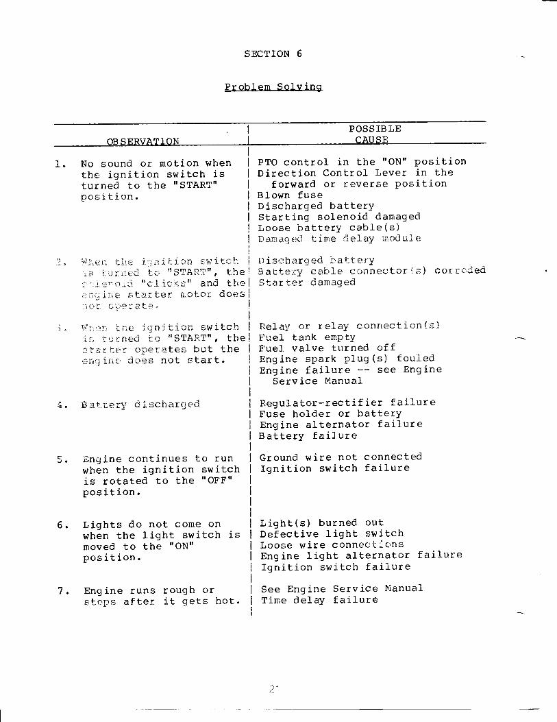
SECTION 6
Problem Solving
. I POSSIBLEOBSERVATION I CAUSE
PTO control in the UON' PositionDirection Control Lever in theforward or reverse PositionBlown fuse
Discharged batteryStarting solenoid damagedLoose battery cable(s)Dama.ged tine rlelaY moduie
Fisetiarqed batteryi3atter:y ca"b'1e connector iB) co)ii rc'''$edStarter danaged
Relay or relay connection{s}Fuel tank emptyFuel valve turned cffEngine spark plug(s) fouleoEngine failure see Engine
Service Manual
Regulator-rectif ier f ailureFuse holder or batterYEngine alternator failureBattery failureGround wireIgnition swi
not connectedtch failure
Light(s) burned outDefective Iight switchLoose wire connec-c icnsEngine light alternator failureIgnition switch failureSee Engine Service lvianualTime delay failure
2n'

I
oB sr':R\/A.r'l oN I
POSS]B LEC AT] SF:
8. Fuse blows when startingeng ine.
9. Hydraulic lift will notlift attachment.
Defective solenoid
Hydraulic valve sealsCylinder sealsLow fluid levelHydraulic pump
22

SECTTON 7
Specifications and Wiring
Fue] specifications see your engine manualFuel- Tank Capac ity 5.3 Gallons (U. S. )(20 liters)Engine oil specification see your engine rranualEngine oil capacity see your engine manuaL
Trarsnission oil specification Apr service sc 10w-3CIMotor Oil
Trani:nrission Oit flapacity 6 euarts (U.S. )(5.7 liters)Ilyel;:au.i ic Fluicl Specif ication ATF Dextron Ifilydraulj.c Fluid Capacity .I euart (U.S.)(.9 liter)Battery 12 Volt, BCl group 22F,
42 amp. hr.Fuse 30 amp. Acc_30Tire Sizes:
Professional L2-c and 16-c Front 16 x 6.50-BRear 23 x 8.50 L2
Professional 18-c and 20-c Front 16 x 7.50 8Rear 23 x 10.50 12
Tire Pressure, Front 14 ps i (97 fu/m2) to18 psi (124 kv/n2lTire Pressure, Rear 10 psi (G9 klg,/m2) ^to14 ps L (97 kN/mz)
23

7.I Grounds Speeds (at 3600 rpm Engine Speed)
FORWARD
'LO' RANGE NHIN RANGE
Gear Soeed Gear Soeed
1 .5 mph ( .8 km,/h) L 2.5 mph ( 4.0 km,zh)
2 .8 mph ( I.2 kmr/h) 2 3.8 mph ( 6 " I kmr/h)
3 1.1 mph ( 1.8 kmrZh) 3 5.7 nrph ( L2 kmy/h)
4 I.7 mph (2.7 kmr/h) 4 8.5 mph (13.7 kmy'hi
REVERSE
rHLn OR nLOn RANGES
Gear Speed
--1 1.1 mph ( I.8 kmr/h)
2 1.7 mph (2.7 kmr/h)
3 2.5 mph (4 .0 km,zh)
4 3 .8 mph ( 6.1 kmrzh)
24
t

7.2 Wiring Diagram:
PTOINTERLOCK SWITCH
SOLENOIDSWITCH
o**-@-" * o**-.@a n owrul I I r
r.
FWD-REVINTERLOCK SWITCH
RED
IGNITIONswlrcH
FUSE
DARKBLUE
REGULATOR
RED
l------[-BLAcKDARKBLUE
CONNECTOR
[][_]
BATTERYSTARTERMOTORWHITE
AMMETER
/---:---\aLncx-{' _ff-*'.'r=-lllr,.HOURMETER
HEADLIGHTS
GREEN
_l_: TIME DELAY
ORANGE
I
GREEN
PUBPLE -J WHITE
25
MODULE
ROwN----{__l--- |
I

SECTION 8
Set-Up Instructions
8.1 Remove the tractor from the shipping container.
8.2 Rear Tire Assembly fnstallation:I. Raise the rear of the tractor.2. Mount the rear wheel assemblies7/I6-20fi/A hub bolts. NOTE:turned toward the inside of thetractors.
to the wheel hub withThe vaJve stem must betwin cylinder engine
3. Lower the tractor.4. Adj.uqt. the air pressurB in the rear tires to r0 psi (69
kN,/mo) to 14 psi (97 kN,/m21.
8.3 Front Tire Assembly Installation:1. Raise the front of the tractor.2. Put two .813x1.375x1.00 flat washers on each front axle.
See Figure 7.
3. Slide a spacer into the grease seal on the val-ve stemside of each front wheef.4. Put multi-purpose grease on each axle.5. Put a wheelr the valve stem towards the insider or! each
ax1e.6. Pack multi-purpose grease into each bearing. Make surethe bearing cages are full of grease.7. slide a bearing, tapered end first, onto each axle. push
the bearings into the wheels.8. Put a spacer and then a .565x1.312x.095 flat washer oneach ax1e. Fasten them with the 5/8" lock nuts.9. Tighten the lock nuts slowly to take up the crearance inthe bearings.NorE: The front wheels must turn freely with no clearancein the beari.ngs.
26

i--Ax1e 6 Spacer2 Flat Washer (.813n I.D.) 7 - FIat Washer (.656n I.D.)3.-Spacer 8-LockNut4-Whee1 9-DustCap5 - Bearing
FIGURE 7
1"0, Install the dust cap.
l,:" Lowen {:he f ront of the tractorI:. Actjuqt the aj-r pressure.,in the front tires to 14 psi t97kN/m') to 18 psi t724 kn/m").
8.4 To Connect the Direction Control Lever:1. Align the hole in the lower end of the direction control
lever with the hol e in the shifter link and neutralreturn strap.
2. Put a clevis pin through the hol-es f rom the outside.3, Secure with a flat washer and cotter pin.
B.5 Steering Wheel Installation:L. PUL the steering wheel bushing on the steering wheei
shaft. Make sure the steering wheel bushing fit-s over t"henylon bushing in the instrument panel. See Figure E.
2" Put tiie nylon bushing on the steering wheel shaft anci j-ni;e;the steering wheel bushing.
3, Put the spring on the steering wheel- shaft"27

7.E\\
3--#t-2v'
-\'\at^''-" -.
'-'
5678
B
1-z-3-4-
Steering Wheel ShaftSteering Wheel BushingNylon BushingSpring
FIGURE
Steering Wheel- Flat Washer- Lock Nut
Steering Wheel Insert
"1. Fut the steering wheel on the steering5 " Put a .656x1.3I2x.095 flat washershaft. fnstall the S/9" Iock nut.torque of 20 ft. Ibs. (27 N,m).6. Install the steering wheel insert.
wheel shaft.on the steering wheeiTighten tne nut :o a
8.6 Seat Installation:1. Tighten the 5/16 hex bolts and Lock washer holding theseat to the seat springs. See Figure 9.2. Align the holes in the seat springs with the holes in theseat pan.3. Fasten the seat _in _position on the seat pan with the5/16x3/4 round head bolts, frat washer, and lock nuts.4. Plug in seat switch.
2B
t--

--4L3I5
1*2-3-4-5-
Seat 6 - Round Head BoltsSeat Springs 7 - Flat l,JasherHex Bolts I - Lock NutsLockWashers 9- PIugSeat Pan
FIGURE 9
29
2.
This Limited Five-Year Warranly is issued by Gravelylnternational, lnc,, only to the original purchaser. lfGravely equipment is leased by Gravely, this Warrantyshall extend also to the original lessee as if suchlessee were the original purchaser.
Gravely warrants that all new equipment manu-factured by Gravely ("Gravely Products") shall be lreeol defects in material and workmanship for lhe termdescribed in paragraph 4, below. Except as hereinafterprovided this Warranty does not cover any engine,tires or battery iorming a part ol the Gravely Product.Engine and iires are covered by and subject toseparate warranlies ol the manufacturers thereof.
ln the event that any Gravely Product,,varrantedhereunder shall be defective or f ailto conform with thisWarranty, Gravely shall, subject to lhe provisronshereof, pay tor, or provide Iabor and materials lor, tnereDair or replacemenl of such defective GravelyProduct
This Warranty is fcr live years (60 months) from,urcrlase rjale f cr Gravely Prod::iriS uSed exClusrvelytor pcrsoltai, i:irnrly or ii.;usehold purposes, and two', ears /:14 rtionths) for prodlcls ilseC ior otherpurposct; iL-o|rlrnei'cial use), excluding rental firrns.Gravely Droducls r.iseC ior renlal p,lrposes will bewarianled 1a)r :i,' days. Reparr of G;avel1 Prcrrjuctsafter li-ie scr..lld year (24 months from date o{f .iichase) inal' tte subject to a $50.0C iJeduciible iirreach re i;;rr ,i,i1 l l,!o years, Gr.avel;,. :gret:s io repaircr.-eplact-: .tclcciive Gravely Products used ex-ciulvu , lor .:,erscnal, famrly or househcld purposLas.)!ti)' i.r :rc .t\ir-:r-rt thal lht. i:osl of such wallantyr.Jvcrert 'e0ati j r .r'i-rlaceineni excer;is $50 00 )
:ailt.fr:l at, r,ittianted 5v G.avel,r, iOr a pertCrCt Cl:werve i12i ,nor:irlS only if a battery sl-rali fail wilhin,t:ri,,,e i1 :r) a it :l-t-q ci nrrrcnase ihe repiaCemenl Cost
ihereoi sh,lrl b(t troraleLr c,vtr a lwelve-monlh terinDaSed uiror-r ih! ruirDej' oi m;n159 Since purChar^e.
I'o itb,lair',Varranl',. Sei'zi.-'e Oir a Gravely PrcduCtiirrcludinq 3n,,, italierv oi o!hi'r comoorent nOi manu-la("iul'eC l/ {lra!€- )/), USe lhts procerlLlre
a. llotify lhe Gri:v'eiy cJeaier irorn whom you pur-'rhascrj the pl,trprncnt
D if ycu have irrOved and it is not convenient lo notilythe seilinc Cealer norify lhe nr-.arest GravelyrJealer. You shculd suppiy thrs dealer with a copyol tne bili ot saie as prool of the dale ol purchase.
c. !lake afranqements to have the equipment oe-livered tc the dealer (refer to paragraph 6 a.,below)
d. lf you have any questions concerning the GravelyLimited Warranty, they should be referred to:
Gravely lnternational, lnc.One Gravely LaneClemmons, NC 27012Attn: Customer Service Deparlment
e. Warranty service on Gravely Products must bepertormed by an authorized Gravely dealer.
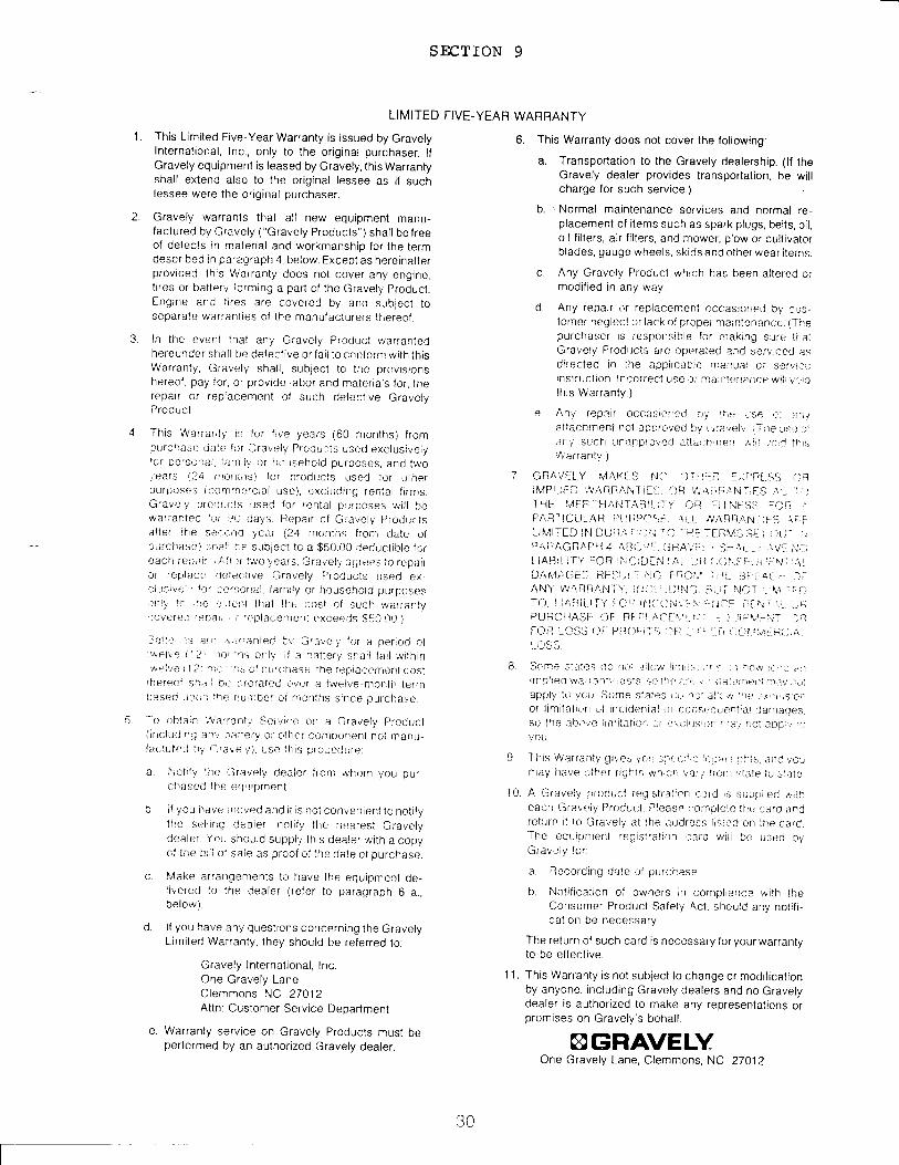
SECTION 9
LI MITED FIVE-YEAR WARRANTY
6. This Warranty does nol cover lhe following:
a. Transporlation to the Gravely dealership. (lf theGravely dealer provides transportation, he willcharge for such service.)
b. ,Normal maintenance services and normal re-placement of items such as spark plugs, belts, oil,oil filters, air filters, and mower, plow or cultivatorblades, qauOe wheels, skids and other wear iterns.
c. Any Gravely Product which has been altered ormodified rn any way.
d. Any repair or replacement cccasjoned by cr-rs.torner negiecl or lacx of prcpei nraintenancc. {ThepUrchaser is responsible for naking Sr.ji'e llratGravely Products arre operated ard serv'jced asdirected in ilte appiicalije nraituai or sef\/r{rrlinsti'uclron. i ncorrect use,tr n-:a jnlerr:.lilce wtil \..rrillhis Warranty.)
e. Any repnir occasicle(j o)i llirj Jse,.ji :,irttattachment not 3p!rLrved by u,'avel,,' I i ne l:e ,lSrty SUCfr r,rnlnprOr'ed aita.thn)err ,.,,tii .,ail 1l)tWarranty.)
7 GnAVf:tY MAKf S t'J:r Oi'rlfr LiL'ni:SS 'lRiMPl tED !\ARFANTiEi.i, {)R w/\rii;,r,Ni]F.il .f ::, 'i_:-l-liE lr/t-hr- l-JAl.il ABll-;l Y ajF riil NFSS ;._iR .1.
FAFTICIjL.AR i'l tnpC-(l:: ,11_L /r'AFnAN'i;L-:S \i: i:LltillTED lll DUil,tii:r'i; rO -tlE -FRVlj SEI i,1r; j ,..rP4|:TAGRAPI-14 Ailtr',.rr: ijllAl:::r,, j:1Ar , , tAV': i.,i,_;LlABll l'f'/ IOR ittl;;i,];,11 IAi Ji? i-)Orr;S'L:;i r:N r ;AiDhL4t"GE', ilEil,L :lNlt; FflOl'4 rilfr !'Jf'r:a/- i 1:'AN\'WARflAi!-i \', li'{.ri '.ji,rri.,lG ;ri.j i \r,'T - V,rrf-lT{), lir.3iL.i l-Y FCI: lil{'rlN-\:\ri,rl jr':F- , r[ f{ i i.i .,]i-iPURCIIAS[ {)F RI t)l ,\i-F !,rt-]fJl : .r liirVrl;l ;r''FC)il t_(,tss {)i: PSor:ir'! r.lli .., r i ,:ir i'( $.ri\ri:ili t;rl
B. Scme slalles (1o iiat ,riicyJ lirlil- ::.r, s iri :rit\lr' ,{'ta ir :{rnDlted'.va,tarnl. tasl,c iii) llra.ir, !- iiAianleIiilr.iV ).i)i
appiy tt, _vCu Some Slatrj:'. tl,; nit'i]lli)r/'nL).:ri',,jSlcrior limitati.rn oi incidenial {_;i crjlsr.rlu€_riiiar .jar|ages,SO the tbi.,,e jtilltlaliOr :/ o ialr.t,sr,Ji, ..)j,, rrot aDn v /lyou.
9 This Warranlv gr\es yrirt :j:,i:.)r{ir-'ieil:r rr(.ltis. iiiC vcr,ilay have 1]ther riOirts wiriotr vatl lrcrri itl3t€r tu ;tale
'1 0. A Graveiy prrlduci rr,:,Jistralrcn c:lrd is suptlired,fliheaci'r Graltiy Prr;dlrcl. Pleasp lrorirDlele thc :iiro andrelurn it to Gravely at lfte itddress l,sied on ttte card.-fhe equiUntent regt.istratlon tard will be used byGtavelv for:
a. I?ecording drrte i:i prrrcl.ase
b. Notification of owners irr compiierrr:e with theConsumer Product Safety Act, shoulC any notifi-calion be necessary.
The return of such card is necessary for your warrantylo be effective.
1 1. This Warranty is not subject to change or modificationby anyone, including Gravely dealers and no Gravelydealer is authorized to make any representations orpromises on Gravely's behalf.
AGRAVELYOne Gravely Lane, Clemmons, NC 27012
t30