Embed Size (px)
Citation preview
Lars Buhrkall, Sviegade 3, DK - 6760 Ribe. Tel. +45 74846011, Email [email protected], www.buhrkall.dk
Traction SystemCase Study
Lars Buhrkall
Electrical engineer
Electrical drives, tractionsystems, and compatibility

Lars Buhrkall, Sviegade 3, DK - 6760 Ribe. Tel. +45 74846011, Email [email protected], www.buhrkall.dk
Case Study?
• Inspiration from Class 357 ”Electrostar”, the Gardermoen Airport Express (Oslo, Norway), and several tender projects.
• Designing a traction package is a multivariable problem and an iterative process – not projects two are equal!
• 6 selected themes that have cost a lot of money!

Lars Buhrkall, Sviegade 3, DK - 6760 Ribe. Tel. +45 74846011, Email [email protected], www.buhrkall.dk
Why are trains different?
• Metro trains: All axles driven, small motors• High speed trains: Locomotives, high powerQ: How many motors, and how much power?

Lars Buhrkall, Sviegade 3, DK - 6760 Ribe. Tel. +45 74846011, Email [email protected], www.buhrkall.dk
Performance Specification• 5 km line• 10 ‰ uphill between
km 1 and km 3• ≤ 4 min run time• 4 car EMU• 2 bogies per car• Max. µ = 15 %• Max. weight 170 t
(How do we know that?)Route profile

Lars Buhrkall, Sviegade 3, DK - 6760 Ribe. Tel. +45 74846011, Email [email protected], www.buhrkall.dk
Generic Tractive Effort curveF (N, kN)
FMAX
PMAX, P = F⋅v
vMAX
v (m/s, km/h)
Determine this curve for 4, 6, and 8 traction motors
Lars Buhrkall, Sviegade 3, DK - 6760 Ribe. Tel. +45 74846011, Email [email protected], www.buhrkall.dk
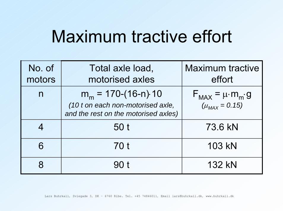
Maximum tractive effort
No. of motors
Total axle load,motorised axles
Maximum tractiveeffort
n mm = 170-(16-n)⋅10(10 t on each non-motorised axle,
and the rest on the motorised axles)
FMAX = µ⋅mm⋅g (µMAX = 0.15)
4 50 t 73.6 kN
6 70 t 103 kN
8 90 t 132 kN

Lars Buhrkall, Sviegade 3, DK - 6760 Ribe. Tel. +45 74846011, Email [email protected], www.buhrkall.dk
Train resistance• Running resistance (friction, aerodynamics):
Numerous formulas, here Filipović:FR(v) = m⋅g⋅(2.5⋅10
-3+ 0.33⋅(v+15)
2⋅10
-6)
• Gradient resistance:FG(s) ≈ m⋅g⋅G(s)/1000 (G in ‰, G ≤ 100 ‰)
• Curve resistance: FC(s) = m⋅g⋅K/r (K ≈ 0.75)
• FACC = F(v) – FR(v) – FG(s) – FC(s)

Lars Buhrkall, Sviegade 3, DK - 6760 Ribe. Tel. +45 74846011, Email [email protected], www.buhrkall.dk
Performance Simulation
• Define an initial F(v) curve• Discrete integration gives v(s):
v(s)2 – v(s-∆s)
2 = 2⋅a⋅∆s, wherea = F(v(s-∆s))/mdyn and ∆s ≈ 1 m
• Time vector t(s):t(s) = t(s-∆s) + 2⋅∆s/(v(s)–v(s-∆s))

Lars Buhrkall, Sviegade 3, DK - 6760 Ribe. Tel. +45 74846011, Email [email protected], www.buhrkall.dk
Calculated run times

Lars Buhrkall, Sviegade 3, DK - 6760 Ribe. Tel. +45 74846011, Email [email protected], www.buhrkall.dk
TE curves

Lars Buhrkall, Sviegade 3, DK - 6760 Ribe. Tel. +45 74846011, Email [email protected], www.buhrkall.dk
Spec compliant systems
No. of motors vMAX PMAX
4 137 km/h 2.0 MW
6 117 km/h 1.2 MW
8 112 km/h 1.08 MW

Lars Buhrkall, Sviegade 3, DK - 6760 Ribe. Tel. +45 74846011, Email [email protected], www.buhrkall.dk
Quick Comparison
No. of motors 4 6 8 8No. of inverters 2 3 4 2No. of motors/inverter 2 2 2 4Peak power - + + +Redundancy - + -Cost DC-supply only (+) (+) -Additional cost AC-supply (+) +

Lars Buhrkall, Sviegade 3, DK - 6760 Ribe. Tel. +45 74846011, Email [email protected], www.buhrkall.dk
Motor and inverter size
Why is the short-term power reduced at high speeds?

Lars Buhrkall, Sviegade 3, DK - 6760 Ribe. Tel. +45 74846011, Email [email protected], www.buhrkall.dk
Basic control of the 3-phase driveThe ASM supplied from a 3-phase inverter:• n ∼ f1• U1/f1 ∼⋅ constant up to fBASE (constant flux)• P ∼ U1⋅I1, T ∼ P/n
f1U1I1T n

Lars Buhrkall, Sviegade 3, DK - 6760 Ribe. Tel. +45 74846011, Email [email protected], www.buhrkall.dk
Motor torqueT = k1⋅VROTOR⋅J⋅B⋅cos(øi), where
VROTOR = active rotor volumeJ = stator current surface densityB = air gap flux density (saturation!)øi = angle between J and B vectors
(increases at increasing J, ⇒ pullout!)

Lars Buhrkall, Sviegade 3, DK - 6760 Ribe. Tel. +45 74846011, Email [email protected], www.buhrkall.dk
Pullout torque
Speed-torque characteristic at constantstator frequency

Lars Buhrkall, Sviegade 3, DK - 6760 Ribe. Tel. +45 74846011, Email [email protected], www.buhrkall.dk
Pullout torque limit at high speedPullout torque vs. voltage and frequency:
TPO = (k2/Lσ)⋅(U1/f1)2
,
where f1 ∼ v, while U1 is limited by the DC link voltage:
u1ωt
π/6 5π/6

Lars Buhrkall, Sviegade 3, DK - 6760 Ribe. Tel. +45 74846011, Email [email protected], www.buhrkall.dk
Inverter power and current• Inverter power: PINV(v) = F(v)/(v⋅η)• Try 2 different base speeds
(different U1/f1 characteristics)• Current: IINV(v) = P(v)/(√3⋅U1(v)⋅cos(ϕ))
U1
F v
PINV

Lars Buhrkall, Sviegade 3, DK - 6760 Ribe. Tel. +45 74846011, Email [email protected], www.buhrkall.dk
Two different designs, equal performance
• Motor size ∼ max. torque• Inverter size ∼ UMAX⋅IMAX

Lars Buhrkall, Sviegade 3, DK - 6760 Ribe. Tel. +45 74846011, Email [email protected], www.buhrkall.dk
Comparison of the two designs
Big motor, small inverter
Small motor, big inverter
Relative motor size (VROTOR)
2.8 1
Relative inverter size (UMAX⋅IMAX)
1 1.7
Requirements on motor cooling
Low High

Lars Buhrkall, Sviegade 3, DK - 6760 Ribe. Tel. +45 74846011, Email [email protected], www.buhrkall.dk
DC Traction and Line Filters
How do we avoid that this nasty current spectrum causes interference with wayside systems?

Lars Buhrkall, Sviegade 3, DK - 6760 Ribe. Tel. +45 74846011, Email [email protected], www.buhrkall.dk
DC Traction Systems
AC motor 3~
Inverter
Line filter and DC link
iDM
+ UDC
-
iLINE
750 V DC / 1500 V DC / 3000 V DC
CD
LLINE HSCB
iM
Interference current generation mechanisms, motor/inverter combination, and line filter design
Lars Buhrkall, Sviegade 3, DK - 6760 Ribe. Tel. +45 74846011, Email [email protected], www.buhrkall.dk
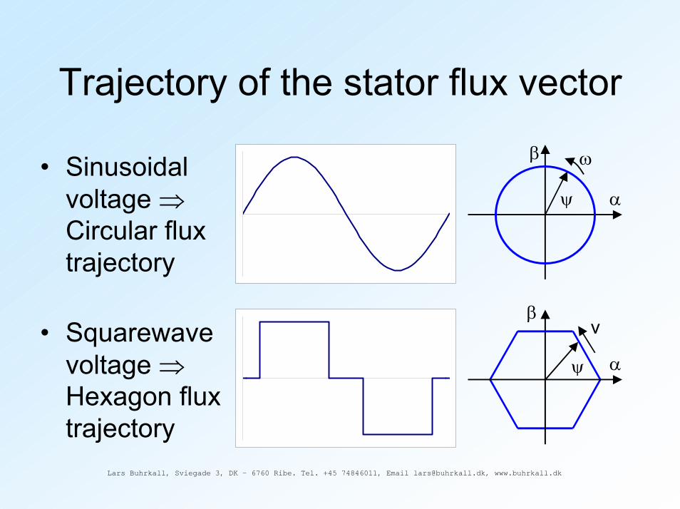
Trajectory of the stator flux vector
α
β
ψ
ω• Sinusoidal voltage ⇒Circular flux trajectory
• Squarewave voltage ⇒Hexagon flux trajectory
α
β
ψ
v

Lars Buhrkall, Sviegade 3, DK - 6760 Ribe. Tel. +45 74846011, Email [email protected], www.buhrkall.dk
Base frequency and Reed track circuit interference
• Hexagon flux polygon ⇒Current components with f = 6⋅fS in iDM
• Reed frequencies: 363 Hz – 423 Hz• fBASE ≤ 70.5 Hz (i. e., big motor, small inverter) ⇒
The 6th harmonic interferes with the Reed band!

Lars Buhrkall, Sviegade 3, DK - 6760 Ribe. Tel. +45 74846011, Email [email protected], www.buhrkall.dk
Low speeds Irregular harmonics• Stop points below base
speed• Aim for a circular flux
polygon• Harmonics due to stops
and shape
• Asymmetries and main circuit imperfections displaces the polygon and/or bends it out of shape
• Stator frequency in iDM!
α
β
ψ
v
α
β
ψ
v

Lars Buhrkall, Sviegade 3, DK - 6760 Ribe. Tel. +45 74846011, Email [email protected], www.buhrkall.dk
DC line filter• Gain of 2nd order L-C filter:
iLINE = iDM/(1-ω2LC)• Typical values:
- Reed limit = 10 mA at 363 Hz- 6th harmonic = 200 A (big motor, small inverter)
• If C = 15 mF, then L ≥ 260 mH !!!• Use small motor / big inverter combo, or
4th order filter, and/or cornerfolding

Lars Buhrkall, Sviegade 3, DK - 6760 Ribe. Tel. +45 74846011, Email [email protected], www.buhrkall.dk
Line side circuits for AC-AC traction systems
How do we avoid this line voltage wave shape?

Lars Buhrkall, Sviegade 3, DK - 6760 Ribe. Tel. +45 74846011, Email [email protected], www.buhrkall.dk
AC-AC Traction
AC motor
2~
3~
4QC Inverter DC link
iD
+ UDC-
+ UB-
+ UL -
iL
15 kV 16 2/3 Hz, 25 kV 50 Hz

Lars Buhrkall, Sviegade 3, DK - 6760 Ribe. Tel. +45 74846011, Email [email protected], www.buhrkall.dk
The short circuit impedance of the main transformer – a key parameter
+ UL-
RT XT
IL
RTIL jXTIL
UB'
IL
UL
∠ψ
~ ~+
UB'-
• IL = (UL-UB’)/(RT+jXT)
• UB is controlled to give cos(ø) = 1:- amplitude- relative angle Ψ
• P ∼ IL ∼ ∆UT

Lars Buhrkall, Sviegade 3, DK - 6760 Ribe. Tel. +45 74846011, Email [email protected], www.buhrkall.dk
2nd harmonic current• Power balance across the 4QC ⇒
iD(t) = ID,DC + îD,2nd⋅sin(2ωt)• The 3-phase drive consumes a
constant power• DC link ripple cause torque pulsations:u1
ωtπ/6 5π/6

Lars Buhrkall, Sviegade 3, DK - 6760 Ribe. Tel. +45 74846011, Email [email protected], www.buhrkall.dk
2nd harmonic link
• Low impedance at the 2nd harmonic ⇒ reduced voltage ripple (tolerances!)
• Supplies the reactive power to the main transformer

Lars Buhrkall, Sviegade 3, DK - 6760 Ribe. Tel. +45 74846011, Email [email protected], www.buhrkall.dk
4QC currents
4QC peak current
∆i u4QC (PWM)
i4QC
√2⋅I1,4QC⋅sin(ωt+ϕ)
tP
A big transformer allows for a smaller converter!

Lars Buhrkall, Sviegade 3, DK - 6760 Ribe. Tel. +45 74846011, Email [email protected], www.buhrkall.dk
4QC voltage spectrum
Voltage spectrum, primary side(3 interlaced bridges)
4QC modulation

Lars Buhrkall, Sviegade 3, DK - 6760 Ribe. Tel. +45 74846011, Email [email protected], www.buhrkall.dk
Line impedanceOHL impedance parameters:• RSERIES
• LSERIES
• CSHUNT
• GSHUNT
ZLINE(f) is subsequently inductive and capacitive, with parallel (highs)and series (lows) resonance points.

Lars Buhrkall, Sviegade 3, DK - 6760 Ribe. Tel. +45 74846011, Email [email protected], www.buhrkall.dk
Line-vehicle resonance
Gain ULINE/U4QC
Line impedance seen from the train
Train impedanceseen from the line
Resonance between the capacitive line and the inductive train (transformer) causes amplifications of harmonics
Examples, 4QC voltage spectra.50 Hz line frequency,250 Hz switching frequency.
Left: 2 interlaced bridgesRight: 4 interlaced bridges
Cable
Line
ULINE
U4QC
Substation transformer

Lars Buhrkall, Sviegade 3, DK - 6760 Ribe. Tel. +45 74846011, Email [email protected], www.buhrkall.dk
Line-vehicle resonance• Seen from the 4QC, the
transformer and the line are in series
• The impedance of the series connection of an inductive transformer and a capacitive line is lowerthan the impedance of the transformer alone
• A high admittance is seen at the resonance point where |XL| = |XC|
From top:• Line and train impedance• Impedance seen from 4QC• Admittance seen from 4QC

Lars Buhrkall, Sviegade 3, DK - 6760 Ribe. Tel. +45 74846011, Email [email protected], www.buhrkall.dk
Relative admittance seen from the 4QC
Relative transformer reactance eX
10 % 40 %
ZLINE is assumed to be 0 4 1
The real line impedance is considered
22 2.1
• A high eX is advantageous• The ”conservative” estimate ZLINE = 0 is wrong!

Lars Buhrkall, Sviegade 3, DK - 6760 Ribe. Tel. +45 74846011, Email [email protected], www.buhrkall.dk
AC line filter
• R damps the resonance• C reduces power losses• Option: L parallel to R
• Upper: Line and train impedance• Lower: Trans-admittance from
4QC to line
2~
4QCDC link
15 kV 16 2/3 Hz, 25 kV 50 Hz
AC line filter

Lars Buhrkall, Sviegade 3, DK - 6760 Ribe. Tel. +45 74846011, Email [email protected], www.buhrkall.dk
Relative (trans-) admittance 4QC to line
Relative transformer reactance eX
10 % 40 %
ZLINE is assumed to be 0 or real line and filter
4 1
The real line impedance is considered, no filter
22 2.1

Lars Buhrkall, Sviegade 3, DK - 6760 Ribe. Tel. +45 74846011, Email [email protected], www.buhrkall.dk
Dual voltage operation (AC and DC)
Step-up chopper or direct-on-line?

Lars Buhrkall, Sviegade 3, DK - 6760 Ribe. Tel. +45 74846011, Email [email protected], www.buhrkall.dk
Dual voltage systems (DC and AC)
AC motor
2~
3~
4QC Inverter DC link
AC DC
AC motor
2~
3~
4QC,chopper
Inverter DC link
AC
DC
• Direct-on-line DC• ≈ 750 V DC link
• Step-up choppers• > 1000 V DC link

Lars Buhrkall, Sviegade 3, DK - 6760 Ribe. Tel. +45 74846011, Email [email protected], www.buhrkall.dk
Comparable 4th order filter configurations
AC motor
2~
3~
4QC Inverter DC link
AC
DC
AC motor
2~
3~
4QC,chopper
Inverter DC link
AC
DC
Equal power rating of components in equal positions gives basically equal performance

Lars Buhrkall, Sviegade 3, DK - 6760 Ribe. Tel. +45 74846011, Email [email protected], www.buhrkall.dk
Relative currents and voltages
Equal power lead to basically equal interference levels
C
+v-
i
i +v-
i i
M C
L L
3AC
DC
C/k2
+ k⋅v-
i/k
i/k+v-
i i
M C
L L
3AC
DC
DC
DC +v-

Lars Buhrkall, Sviegade 3, DK - 6760 Ribe. Tel. +45 74846011, Email [email protected], www.buhrkall.dk
Harmonic intermodulation• If the DC link voltage (the high
voltage side of the chopper) is ideally smooth, only the chopper frequencies (here n⋅300 Hz) are seen at the low voltage side.
• Any DC link ripple, e. g., at 50 Hz, is also seen at the LV side. The chopper acts as a transformer.
• But also a 350 Hz ripple causes a 50 Hz component, due to intermodulation with the 300 Hz chopper frequency.
Harmonic components at the LV side

Lars Buhrkall, Sviegade 3, DK - 6760 Ribe. Tel. +45 74846011, Email [email protected], www.buhrkall.dk
Dual system - conclusion
• Step-up choppers should only be used if the traction power is so high that the current rating of the 3-phase inverter becomes impractical at direct-on-line supply.

Lars Buhrkall, Sviegade 3, DK - 6760 Ribe. Tel. +45 74846011, Email [email protected], www.buhrkall.dk
Testing and approval
Interference tests
Tractiveefforttests
Compatibility tests
Wintertests

Lars Buhrkall, Sviegade 3, DK - 6760 Ribe. Tel. +45 74846011, Email [email protected], www.buhrkall.dk
The purpose of testing
• Convince yourself• Convince your customers• Convince the responsible authorities

Lars Buhrkall, Sviegade 3, DK - 6760 Ribe. Tel. +45 74846011, Email [email protected], www.buhrkall.dk
Convince yourself
• Component tests• Subsystem and prototype tests• Control systems tests using real time simulators• Combined system tests and type test• Commissioning and testing of 1st vehicle
” - I’m convinced. I have shown that my calculations are right”.” - But I could easily make your equipment fail!”

Lars Buhrkall, Sviegade 3, DK - 6760 Ribe. Tel. +45 74846011, Email [email protected], www.buhrkall.dk
Convince your customer
• Run time tests• Endurance tests• Tractive effort tests• Climatic tests

Lars Buhrkall, Sviegade 3, DK - 6760 Ribe. Tel. +45 74846011, Email [email protected], www.buhrkall.dk
Convince the authorities
• Deregulations ⇒ undefined situations in most European countries
• Every country is different• Address this problem from day 1:
- Technical requirements- Acceptance process

Lars Buhrkall, Sviegade 3, DK - 6760 Ribe. Tel. +45 74846011, Email [email protected], www.buhrkall.dk
Subjects for approval• EU directives (e. g., EMC)• International standards (EN, IEC, UIC)• National legislation• Local specifications (e. g., interference limits,
climatic conditions, etc.)• What has not been specified?
- Local traditions- The already existing systems(vehicles, power supply)
Act responsible!