Embed Size (px)
Citation preview

TraceNet™ TCSeries Control System
TCM18 Panel Installation, Start-Up,and Maintenance Guide
Thermon Manufacturing Company
TraceNet™is a registered trademark of Thermon Manufacturing Company.
PN 50312

TCM18 Panel Installation and Start-Up Guide©2013 Thermon Manufacturing Company. All Rights Reserved.
This guide, as well as the firmware described in it, is furnished under license and may only be used orcopied in accordance with the terms of such license. The information in this guide is furnished for infor-mational use only, is subject to change without notice, and should not be construed as a commitment byThermon Manufacturing Company. Thermon Manufacturing Company assumes no responsibility or liabil-ity for any errors or inaccuracies that may appear in this guide.
This documentation is considered proprietary and is protected by copyright. This document may not, inwhole or in part, be copied, photocopied, reproduced, translated, or reduced to any electronic medium ormachine-readable form without prior consent in writing from Thermon Manufacturing Company.
This information is subject to change without notice. It is recommended that a quick check of the currentrevision status be done at www.Thermon.com prior to proceeding.
This guide is written and designed at Thermon Manufacturing Company, 100 Thermon Drive, San Marcos,TX 78667-0609, USA.
Copyright ©2013 Thermon Manufacturing Company. All Rights Reserved.
PRODUCT WARRANTY INFORMATIONThe seller warrants all equipment manufactured by it to be free from defects in workmanship or materialunder normal use and service. If any part of the equipment proves to be defective in workmanship ormaterial and if such part is, within 12 months of the date of shipment from sellers factory, and if the sameis found by the seller to be defective in workmanship or material, it will be replaced or repaired, free ofcharge, F.O.B. the seller’s factory. The seller assumes no liability for the use or misuse by the buyer, hisemployees, or others. A defect within the meaning of this warranty in any part of any piece of equipmentshall not, when such part is capable of being renewed, repaired, or replaced, operate to condemn suchpiece of equipment. This warranty is in lieu of all other warranties (including without limiting the generalityof the foregoing warranties of merchantability and fitness for a particular purpose), guarantees, obligations,or liabilities expressed or implied by the seller or its representatives and by statue or rule of the law.
PN 50312_0414

Contents
Chapter 1: Introduction. . . . . . . . . . . . . . . . . . . . . . . . . . . . . . . . . . . . . . . . . . . . . . . . . . . . . . . . . . . . . . . . . . . . . . . . . . . . . . . . . . . . . . . . . . . . . . 1
Chapter 2: Panel Specifications. . . . . . . . . . . . . . . . . . . . . . . . . . . . . . . . . . . . . . . . . . . . . . . . . . . . . . . . . . . . . . . . . . . . . . . . . . . . . . . . . . . . . . . . . . . . . . 3
Chapter 3: Module Connections. . . . . . . . . . . . . . . . . . . . . . . . . . . . . . . . . . . . . . . . . . . . . . . . . . . . . . . . . . . . . . . . . . . . . . . . . . . . . . . . . . . . . . . . . . . . . . 5
Chapter 4: Field and Panel Wiring. . . . . . . . . . . . . . . . . . . . . . . . . . . . . . . . . . . . . . . . . . . . . . . . . . . . . . . . . . . . . . . . . . . . . . . . . . . . . . . . . . . . . . . . . . . . . . 9
Chapter 5: The User Interface. . . . . . . . . . . . . . . . . . . . . . . . . . . . . . . . . . . . . . . . . . . . . . . . . . . . . . . . . . . . . . . . . . . . . . . . . . . . . . . . . . . . . . . . . . . . . . 13
Chapter 6: Heat Trace Control. . . . . . . . . . . . . . . . . . . . . . . . . . . . . . . . . . . . . . . . . . . . . . . . . . . . . . . . . . . . . . . . . . . . . . . . . . . . . . . . . . . . . . . . . . . . . . 21
Chapter 7: System Start-Up. . . . . . . . . . . . . . . . . . . . . . . . . . . . . . . . . . . . . . . . . . . . . . . . . . . . . . . . . . . . . . . . . . . . . . . . . . . . . . . . . . . . . . . . . . . . . . 23
Chapter 8: Maintenance. . . . . . . . . . . . . . . . . . . . . . . . . . . . . . . . . . . . . . . . . . . . . . . . . . . . . . . . . . . . . . . . . . . . . . . . . . . . . . . . . . . . . . . . . . . . . . 24
Chapter 9: Notes. . . . . . . . . . . . . . . . . . . . . . . . . . . . . . . . . . . . . . . . . . . . . . . . . . . . . . . . . . . . . . . . . . . . . . . . . . . . . . . . . . . . . . . . . . . . . . 29
Chapter 10: More Information. . . . . . . . . . . . . . . . . . . . . . . . . . . . . . . . . . . . . . . . . . . . . . . . . . . . . . . . . . . . . . . . . . . . . . . . . . . . . . . . . . . . . . . . . . . . . . 30
Appendix A:. . . . . . . . . . . . . . . . . . . . . . . . . . . . . . . . . . . . . . . . . . . . . . . . . . . . . . . . . . . . . . . . . . . . . . . . . . . . . . . . . . . . . . . . . . . . . . 31
Appendix B:. . . . . . . . . . . . . . . . . . . . . . . . . . . . . . . . . . . . . . . . . . . . . . . . . . . . . . . . . . . . . . . . . . . . . . . . . . . . . . . . . . . . . . . . . . . . . . 43
Appendix C:. . . . . . . . . . . . . . . . . . . . . . . . . . . . . . . . . . . . . . . . . . . . . . . . . . . . . . . . . . . . . . . . . . . . . . . . . . . . . . . . . . . . . . . . . . . . . . 44
PN 50312_0414

1 Introduction
The following serves as a general guide and overview on the installation and startup ofa TraceNet TC Series heat tracing control panel. This guide shall be used in conjunc-tion with the project specific control system drawings and any other standard installationinstructions/guides provided. In the unlikely event that a conflict or uncertainty arises,contact the Thermon engineering support personnel assigned to this project to clarify.
All installation personnel should be properly trained and qualified to safely install, service,and program this TraceNet heat tracing control panel as well as to operate the associatedheat tracing system.
THE PANEL LOCATION
A wide variety of TraceNet TC Series panel configurations are possible. The TraceNetmodules are designed to operate in ambients ranging from -40◦F (-40◦C) to 140◦F (60◦C)and higher. The TraceNet panels can be located in site locations having electrical clas-sifications ranging from ordinary to hazardous. The actual panel markings provided withthe panel will detail the design intended specific location requirements.
INITIAL INSPECTION AND HANDLING
Upon receiving the TraceNet TC Series panel, it is important to confirm that the contentsof the shipping containers agree with the shipping documents and with the purchase or-der. Also, it is important to check the shipped container exterior and packing materialsfor any possible freight damage. Where damage is observed, take photos and notify thecarrier as well as your nearest Thermon engineering support center before proceedingfurther.
After carefully removing the panel from its shipping container, move the panel to its se-lected location utilizing the pallet base and the securement strapping provided using alift truck/fork lift. Where lifting eyes are provided on the panel, they should be used whenhandling.
Where the panel has external heat sinks to dissipate the heat generated by solid state
1 PN 50312_0414

relay switching, it is recommended that a minimum of 6” (150 mm) of space be allowedbetween sinks and walls or other panels to minimize heat buildup at the heat sinks.Where heat sinks are present on adjacent panels, allow 12” (300 mm) spacing betweenheat sinks for sufficient natural air movement.
Adequate door clearance for service work entry and conduit panel entries should beanticipated when establishing the exact panel location. When the panel is located out-doors, a concrete base pad of sufficient height to avoid potential standing water shouldbe constructed.
Once the panel has been properly located, refer to the project specific installation detailsfor the recommended floor mounting as well as wall mounting details.
Once bolted in place, the panel is ready for final configuration, wiring, and site requiredassembly. Note that the TCM18 control and monitoring module is normally shipped in aseparate container to minimize any undue impact stress during shipment. It should beremoved from its shipping container again being attentive to any shipping damage thatmay have occurred during its transit. The TCM18 mounting details are likewise providedin the project specific drawing details.
Note: For installation requirements specific to purged panels, please see Appendix B.
2 PN 50312_0414

2 Specifications
The general TraceNet TC Series panel specifications are as given below.
Interior panel operating ambient range -40◦F to 140◦F (-40◦C to 60◦C)
Exterior panel operating ambient range -40◦F to 131◦F (-40◦C to 55◦C)
Ambient storage range -40◦F to 158◦F (-40◦C to 70◦C)
Relative humidity range 0 to 90% Non Condensing
Nominal instrument control voltage 100 to 240 Vac, 50/60 Hz
Temperature sensor types 100 Ohm 3 Wire Platinum RTD
Control temperature range -200◦F to 1112◦F (-129◦C to 600◦C)
Maximum power consumption of TCM18 module 70 Watts
Current ratings in hazardous (classified) locations based on TraceNet TC Series panelsfor up to 72 circuits are as follows1:
Maximum Panel ExteriorAmbient (◦C)
For: 1 - 36 Circuits For: 37 - 72 Circuits
Maximum Allowable Average Amps per Relay
(Calculated for each side of enclosure)2
40 22.2 18.045 21.0 16.850 19.7 15.655 18.3 14.3
3 PN 50312_0414

Current ratings in nonhazardous (ordinary) location based on TraceNet TC Series panelsfor up to 72 circuits are as follows1:
Maximum Panel ExteriorAmbient (◦C)
For: 1 - 36 Circuits For: 37 - 72 Circuits
Maximum Allowable Average Amps per Relay
(Calculated for each side of enclosure)2
20 27.0 22.725 25.8 21.630 24.7 20.435 23.5 19.240 22.2 18.045 21.0 16.850 19.7 15.655 18.3 14.3
Note 1: Contact the manufacturer for the maximum allowable amps per relay for custom enclosure sizes.
Note 2: Based on factory panel wiring rated for 105◦C.
TCM18 LCD heated display 1-3/4” ( 44 mm) x 4.875” (124 mm)
TCM18 touchpad tactile feel, stainless steel dome keys
TCM18 communication 2 RS485 ports
TCM18 operating temperature range -40◦F (-40◦C) to 140◦F (60◦C)
TCM18 alarm relay outputs -U Option Three, sealed dry contacts rated @0.4 Amp, 24 Vdc
-A Option Three, sealed dry contacts rated 100-240 Vac @ 0.5A
Entries into panels must meet IP54 and/or NEMA-4 ingress protection levels to maintainthe environmental rating of the panel.
4 PN 50312_0414
3 Module Connections
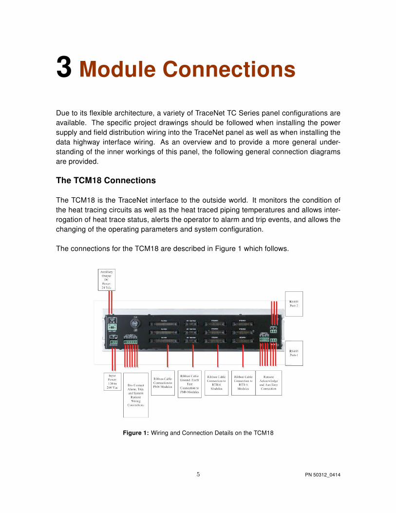
Due to its flexible architecture, a variety of TraceNet TC Series panel configurations areavailable. The specific project drawings should be followed when installing the powersupply and field distribution wiring into the TraceNet panel as well as when installing thedata highway interface wiring. As an overview and to provide a more general under-standing of the inner workings of this panel, the following general connection diagramsare provided.
The TCM18 Connections
The TCM18 is the TraceNet interface to the outside world. It monitors the condition ofthe heat tracing circuits as well as the heat traced piping temperatures and allows inter-rogation of heat trace status, alerts the operator to alarm and trip events, and allows thechanging of the operating parameters and system configuration.
The connections for the TCM18 are described in Figure 1 which follows.
Figure 1: Wiring and Connection Details on the TCM18
5 PN 50312_0414

The RTB6 Module Connections
The RTB6 module allows the connection of six 3-wire 100 Ohm platinum RTD inputs tothe TraceNet control system. The RTB6 circuit board is a passive device which commu-nicates the discrete temperature inputs into a 26 pin bundled ribbon cable which theninterconnects to a TCM18 module.
The connections within a TraceNet panel for the RTB6 are shown in the illustration whichfollows.
Figure 2: RTB6 Wiring and Connections
6 PN 50312_0414

The PM6 Connections
The PM6 serves as the heat trace power solid state switching module for a TraceNetTCM18 controller. It includes the heater and ground current measurement transformers,solid state heat trace control relays, and the heat dissipating heat sink. This module in-cludes a ground leakage functional test circuit. In addition, alarm and trip output capabil-ity to indicating lights on the panel front door are also provided.The module connectionsfor the PM6 are as detailed in the following illustration.
Figure 3: PM6 Wiring and Connections
7 PN 50312_0414

The RM6 Connections
The RM6 is a DIN rail mounted six circuit relay interface module for linking to individualsolid state or mechanical relays via ribbon cable from the TCM18 controller. The RM6includes individual terminal strips which allow the interconnection of individually mountedheater and ground current sensing transformers. This module is primarily used wherecustom current transformers, solid state relays with integral heat sinks, or individual pilotand mechanical relays are to be used. The module connections for the RM6 are as de-tailed in the following illustration.
Figure 4: RM6 Wiring and Connections
When receiving a new TraceNet TC Series control panel shipment, it is recommendedthat all module connections within the panel be re-torqued to the recommended tightnesslevels as provided in the project panel drawing and in Table 1 Chapter 4. Occasionally,it is possible that handling and shipment can loosen some wiring terminations orcomponents cables.
Servicing allowed for removable electrical connectors only when the area is known to befree of explosive atmospheres.
8 PN 50312_0414

4 Field and Panel Wiring
For a successful installation of a TraceNet TC Series heat tracing control and monitoringpanel, a number of equally critical parts of the system must be installed properly. Areasrequiring close attention are the heat trace and insulation, the RTD temperature sensorinstallation, the distribution of the field RTD and power wiring, and the installation androuting of wiring inside the TraceNet panel.
The heat tracing system installation shall be in accordance with the electrical area clas-sification requirements as well as shall conform to the latest requirements as detailed inapplicable heat tracing standards, the local Electrical Code and plant standard practices.Where conflicts arise, contact the project engineer for resolution.
Heat Trace and Insulation Installation
All heat trace circuits and insulation shall be installed in accordance with project instal-lation details provided. In addition, refer to the Electric Heat Tracing Maintenance andTroubleshooting Guide (Thermon Form No. 20745) for general procedures and installa-tion tips.
RTD Installation and Wiring
RTD control sensors should generally be installed on the process lines or in ambi-ent(where ambient sensing is applied) in a location that is most representative of theentire heat trace circuit. In general, it is recommended that the sensors not be locatedat heat sinks such as pipe supports, pumps, and valves as the control system responseneeds to be based on the majority of the process line. The RTD control sensor locationon the process piping should follow the guidelines detailed below.
9 PN 50312_0414

Figure 5: RTD Sensor Location
Where limiter RTD sensors are installed on the process piping it should follow the guide-lines above. In cases where the limiter is to be installed on the heater itself, it is importantto recognize that an offset should be anticipated in the limiter trip value to allow for sen-sor reading error and overshoot.
As a general rule, field RTD wiring and power wiring should not be routed in the sameconduit or proximity in a tray as the temperature signals can become distorted and resultin improper readings.
Power Distribution Wiring and Breakers
All field power wiring materials used shall be suitable for the intended service and shallbe rated for insulation service temperatures up to and exceeding 221◦F (105◦C) unlessotherwise higher values are noted in project specifications. Power supply wiring fromthe power transformers to the power distribution panel and distribution wiring to the heattrace circuits shall be rated for the heat trace use voltage or higher and sized sufficientlylarge in wire size to minimize voltage drop. Circuit breakers if not already supplied inthe TraceNet panel should be selected based on the heat trace cable type being used,the service voltage, and the circuit current draw characteristics. It is especially importantwhen using self regulating cable to make sure that the circuit breaker response curvetype is coordinated with the startup characteristic of the heat trace cable in a cold startcondition. All distribution wiring connections should be tightened using a torque indicat-ing screw driver to the levels indicated in Table 1.
10 PN 50312_0414

Location of Terminals Torque Values (Typical)*
RTB6 5.3 to 7.0 in. lbs. (0.60 to 0.79 N-m)
PM6 12.5 to 13.5 in. lbs. (1.41 to 1.53 N-m)
Distribution Equipment 13.2 to 15.9 in. lbs. (1.49 to 1.80 N-m)
*Required torque values may vary depending on individual panel designs and size ofterminals. Refer to project documentation for additional information.
Table 1: Recommended Torque Values
TraceNet Panel Wiring
TraceNet TC Series panels are configured and prewired into an integrated heat tracecontrol and monitoring system. Clean terminal strips are provided to facilitate the fieldwiring into the panels. Refer to the project specific panel drawings when installing thefield wiring within the panel. Field wiring is conventionally shown by dashed lines. Allfield power wiring materials used shall be suitable for the intended service and shallbe rated for insulation service temperatures up to and exceeding 221◦F (105◦C) unlessotherwise higher values are noted in project specifications. All TraceNet componentsterminal block connections should be tightened using a torque indicating screw driver tothe levels indicated in Table 1.
Serial Communication Wiring
TraceNet TC Series panels may be linked together for communications with a RS485communication cable at distances up to 4000 feet (300 m.) or more. In addition, a ter-mination module should be used at each end of the RS485 network. The recommendedcommunication cables for use in the RS485 network are as given in Table 2 which fol-lows.
11 PN 50312_0414

Cables for RS485 Communication
CableType Recommended
120 Ohm, -20 to +60 C 22AWG FHDPEinsulation PVC outer jacket
Belden 3107A or equal
120 Ohm, -30 to +80 C 24AWG PE insula-tion PVC outer jacket
Belden 9842 or equal
120 Ohm, -70 to +200 C 24AWG TeflonFFEP insulation Teflon FEP outer jacket
Belden 89842 or equal
Note all these products are designated as 120 ohm impedance for balanced line com-munication uses.
Table 2: Recommended RS485 Cable Type
12 PN 50312_0414

5 The User InterfaceThe TCM18 functions as the user interface for a TraceNet TC Series control panel net-work of heat tracing control modules. The TCM18 allows the operator to access oper-ating control parameters and operating conditions throughout the heat tracing systemnetwork.
There are four display message lines on the TCM18 display. All interfacing to the TCM18and the heat tracing circuit information is via the dedicated tactile feel membrane touch-pad and the companion four line LCD display as shown in Figure 6
Figure 6: TCM18 Control and Monitoring Module Front Panel
On power up, the TCM18 will display the following start-up screen message:
THERMON TCM18COPYRIGHT 2013
Figure 7: TCM18 Start-Up Screen
After this start-up message, the TCM18 will immediately proceed to operation in its SCAN
13 PN 50312_0414

MODE.
The TCM18 will operate in a heat tracing circuit SCAN MODE during normal operation.That is, the LCD display will automatically scroll through each enabled heat tracing cir-cuit number, indicating the actual measured temperature and the control set point formaintain temperature on the first two display screen lines. The third display screen linewill indicate the heater status (ON % or OFF) and the heat tracing circuit heater currentvalue. The fourth display screen line will indicate any alarm(s) present on the circuitdisplayed. Where multiple alarm events occur on a circuit, the TCM18 will display onlyone alarm message at a time until all have been cleared. A typical SCAN MODE screenwhen the heat tracing circuit is operating normally is as shown below in Figure 8:
CKT 7 TEMP= 61◦CMAINTAIN TEMP= 60◦CHEATER ON 80% 12.0A
Figure 8: Typical TCM18 information when in SCAN MODE
Note that the fourth message line on the display screen will be empty as long as there areno alarm or trip conditions present on a given circuit. During SCAN MODE, the TCM18will sequence through all enabled heat tracing circuits beginning with the first circuit andthen loop back to the first circuit after displaying the last circuit and repeat the scanningprocess.
To access information on a specific heat tracing circuit, press the appropriate yellow orred key. Pressing these keys will directly access the information and functions associ-ated with that key. As a typical example, press the MAINTAIN TEMP key as shown inFigure 9.
14 PN 50312_0414

Figure 9: TCM18 Touch Pad
This will result in the display screen response as illustrated below in Figure 10.
CIRCUIT = 7MAINTAIN TEMPERATUREMAINT= 49◦C
Figure 10: TCM18 LCD Response
The TCM18 has an electronic password security provision. To access the programmingmode, enter the 4 digit numerical security code. If no code has been entered, press thePROG key followed by the ALARM ACK key and subsequently followed by the PROGkey. Next, successively select a numerical code using the UP and DOWN arrow keysalong with the ENTER key. An entry of 0000 will deactivate the security code feature.Note that once a security code has been entered, the user has unlimited access as longas activity is present. A period of inactivity of 30 minutes or more will result in program-ming access being denied. At this point, re-entry of the security code will be required. Ifthe security code is forgotten at some future date, enter a value of 1954 (during the first 5
15 PN 50312_0414

minutes after power is applied to the TCM18) as the security code, then a new code maybe entered by pressing the ALARM ACK key and subsequently followed by the PROGkey.
To program circuit control settings or control parameters, multiple keys in sequence willneed to be pressed. For example, to change the settings associated with the MAINTAINTEMP key, first press the green PROG key.
Figure 11: TCM18 PROG Key
The Display now reads as shown below:
PROGRAM MODE ENABLEDSELECT FUNCTION KEY
Figure 12: Program Mode Enabled
Press the MAINTAIN TEMP key.
16 PN 50312_0414

Figure 13: MAINTAIN TEMP Key
The Display now reads as shown below with the flashing cursor z representing the activedata entry field:
PROGRAM CIRCUIT = 7zMAINTAIN TEMPERATUREMAINT= 49◦C
Figure 14: Programming Maintain Temperature
Pressing the green UP or DOWN Arrow programming keys followed by the green EN-TER key allows the selection of the heat tracing circuit to program.
17 PN 50312_0414

Figure 15: Programming Keys
The display screen will now shift the cursor to the next value to program as shown in thefollowing display.
PROGRAM CIRCUIT = 7MAINTAIN TEMPERATUREMAINT= 49◦C← 49◦Cz
Figure 16: Changing Maintain Temperature
A single press of the green UP or DOWN arrow programming key will increase or lowerthe Maintain Temperature set point by a single degree. Holding these keys down willincrease the indexing speed for cases where a significantly large increase or decreasein set point is required. Once the new set point is reached, press the green ENTER keyto save the new set point.
18 PN 50312_0414

Figure 17: The ENTER Key
The DISPLAY screen now appears as shown in Figure 18.
PROGRAM CIRCUIT = 7zMAINTAIN TEMPERATUREMAINT= 52◦C
Figure 18: Selecting a New Circuit Number
At this point, pressing the green UP or DOWN arrow key will select the next heat tracingcircuit to program. Alternatively, press the green PROG key to exit and return to SCANMODE. However, if for some reason this is not done, the screen will automatically returnto SCAN mode operation.
19 PN 50312_0414

TIP: In many cases, the programmed value can be the same for a majority of heat tracingcircuits. Note that when sequencing through the circuit numbers, there is an ALL option.This allows the programming of the same set point for all circuits on this particular TCM18module and permits only entering the set point once. When selecting the ALL option, thevalues programmed into the first circuit will initially appear as a starting point for anyvalue changes.
This TCM18 user interface should be found to be very intuitive and require minimal train-ing to perform day to day operations. The TraceNet system is a fully featured heat tracecontrol and monitoring system and thus has many advanced options in setup and con-figuration. A companion document “TCM18 Operating Guide - PN 50308” included withthe documentation package covers the full features of this interface in much more detail.
20 PN 50312_0414

6 Heat Trace Control
The TraceNet system allows a variety of control options for heat trace operation. Themost energy efficient control mode is to use one or more process sensing RTD’s foreach heat trace circuit. When configured with two RTD sensors, TraceNet will controloff of the lowest reading and alarm off of the highest reading encountered. In the caseof process sensing control, however, one must be aware of the normal flow directionswithin the process piping and only group process piping having a common flow conditionwith the control sensors. A failure to do so can result in non flowing areas cooling andfreezing where the flowing portions have appropriately turned the heat trace circuit off.Process sensing control is also a necessity where steam outs and high exposure tem-perature process conditions are expected and where the heat trace (due to its inherentcharacteristics) cannot be operated during such events. When using this control mode,the TraceNet TC Series panel will have RTD’s hard wired directly back to the panel.
As an alternate control mode which is a bit less energy conservative, the TraceNet TCSeries panel may be configured for Ambient Proportional Control (APC). In this case,one or two RTD’s may be used to sense ambient temperatures in the process area.The heat trace will be set to operate at 100% power at the maintenance temperature(which is the minimum ambient condition) and then ramp down to a 20% power levelat the maintenance temperature plus the control band. If the ambient rises above thisvalue, the heat trace will then turn off. For example, to freeze protect a process unit ina minimum ambient of -40◦F (-40◦C), one would set the circuit to operate on APC. TheMaintenance Temperature (at or below which power is on 100%) would be programmedto be a value of -40◦F (-40◦C). The Control Band would be set to 90◦F (50◦C) and thusthe heat trace circuit would turn off above 50◦F (= -40 + 90) or 10◦C (= -40 + 50) am-bient conditions. Obviously, this type of control mode will reduce RTD requirements butstill achieve a good measure of temperature control. In addition, due to the amount ofpower cycling it is important to realize that this should only be utilized when using solidstate relay switching of the heat tracing circuits. APC control should not be used wheresteam outs and high exposure temperature process conditions are expected and wherethe heat trace due to its inherent characteristics cannot be operated during such events.
As a third control mode option, which is a less energy conservative approach, theTraceNet TC Series panel may be configured for Ambient ON/OFF Control. In this case,one or two RTD’s may be used to sense ambient temperatures in the process area. Theheat trace will be set to operate at 100% power whenever the ambient temperature drops
21 PN 50312_0414

below the maintenance temperature which is typically set at 50◦F (10◦C). If the ambientrises above this value, the heat trace will turn off. Obviously, this type of control modewill also reduce RTD requirements. In this case, there will naturally be some tempera-ture overshoot expected in the process as the ambient approaches the turn off point. Inthis case, mechanical relay switching of the heat tracing circuits may be used. AmbientSensing ON/OFF control should not be used where steam outs and high exposure tem-perature process conditions are expected and where the heat trace due to its inherentcharacteristics cannot be operated during such events.
22 PN 50312_0414

7 System Start-Up
For information on entering and/or changing individual control and monitoring parame-ters through the TCM18, refer to the System Start-Up Operating Guide PN 50308.
Starting Up the Heat Trace System
All heat trace circuits should be properly terminated and meggered prior to energizingthe heat trace power distribution and control panels. In addition, all pipes should be insu-lated and weather sealed to achieve the expected heat up and temperature maintenanceperformance of the system.
Troubleshooting Tips
When starting up a newly installed heat trace and control system, it is not uncommonto encounter numerous alarm and trip events. Data entry errors, unanticipated tempera-ture overshoots due to system inertia or too tight control band settings, and incompleteinstallation details are just a few of the many contributing factors to this result. A table ofTroubleshooting Tips is provided in Appendix A to assist during start-up.
23 PN 50312_0414

8 Maintenance
Preventative maintenance consists of inspection, testing, checking connections, andgeneral cleaning of equipment at scheduled intervals. The maintenance recommen-dations that follow are intended to support and in some cases “add to” those proceduresdetailed in the facility’s Planned Maintenance System (PMS). In case of conflicts, con-tact the project engineer for resolution. When carrying out the scheduled maintenanceprogram, the following safety precautions should be observed.
Safety Precautions
The heat tracing can be powered by the project specified nominal voltages ranging from100 to 600 Vac. It is important that only authorized trained personnel conduct thesemaintenance and service activities. Before conducting any maintenance or service pro-cedure, exercise required lockout and tag out procedures at the appropriate circuit break-ers. Additionally, do additional testing within the control panel to ensure that the specificheat tracing and control circuit of interest is fully de-energized and the equipment isgrounded.
If it becomes necessary to service or test live equipment, the following instructions mustbe followed:
• Use one hand when servicing the equipment. Accidental death or severe injurymay occur especially if a current path is created through the body from one handto the other.
• First, de-energize the equipment. To de-energize any capacitors connected intothe circuits, temporarily ground the terminals where work is to be done.
• Connect the multi-meter/instrument to the terminals of interest using a rangehigher than the expected. Make sure that you are not grounded whenever aneed arises to adjust equipment or test circuit operation. Verify that all testequipment used is properly maintained and safe for the intended use.
• Without touching the multi-meter/instrument energize the equipment and readthe values indicated on the multi-meter/instrument.
• Remove the test leads after de-energizing the circuit of interest.
24 PN 50312_0414

Maintenance Schedule Recommendation
The service schedule is somewhat dependent on the “in service” hours. As a generalrule, however, it is recommended that the heat tracing control and monitoring panel beserviced on a twelve month basis to start. The schedule may be adjusted depending onthe operating history of the panel and as the historical maintenance records dictate. Therecommended typical list of tools and test equipment follows:
Tools Comment
Multimeter Calibrated and in Safe Working Order
Flashlight
Vacuum Cleaner Nonmetallic Nozzle
Screw Drivers Standard as Well as Torque Type
Wrenches Standard as Well as Torque Type
Fuse Extractor
Stiff Bristle Wire Brush
Infrared Camera Helpful in Checking Out Connections
The recommended spare parts inventory list for this panel follows:
Spare Parts Description Quantity
TCM18 Control Module
PM6
D2450 SSR Relay
D60125 SSR Relay
D6090 SSR Relay
25 PN 50312_0414

The recommended typical list of cleaning materials follows:
Materials Comment
Lockout and tag out safety tags
Dry lint free cloths
Cleaning agent
Medium grit sandpaper
Touch up paint
Machine oil
Grease
Electrical tape Refer to specific panel materials list fortapes being used. Use only Thermon ap-proved or equivalent materials.
Damp cloth To avoid electrostatic discharge, clean win-dow with damp cloth only.
Recommended Visual Inspection Procedures
The interior and exterior of the control and monitoring panel should be inspected as fol-lows:
• Inspect door and /or heat sink gaskets for water intrusion as indicated by mineraldeposits and rust. Where feasible replace any gaskets which appear to be faulty.
• Survey panel exterior and interior for dust, lint, moisture, or foreign residue.Remove any such residue with the lint free cloth material. Heavy residues maybe addressed with wood scrapers and a cleaning agent. Do not soak partswith cleaning agent but only use dampened cloths in removing heavy residues.Excessive application of cleaning agents can damage components.
• Check for panel corrosion and scratches. Remove corrosion and prepare anydamaged areas with sandpaper. Repaint with the approved primer and touch uppaint.
• Check door hinges, latches, and other moving parts for proper operation. Usemachine oil to lubricate the moving parts and restore proper operation wherenecessary.
26 PN 50312_0414

• Check for mechanical damage to any windows as well as check the windowseals. Repair or replace damaged materials.
In all cases where equipment damage is observed, a root cause analysis should be ini-tiated to determine any future corrective action needed to prevent a recurrence.
Wiring and Connections Survey
The wiring and connections survey recommended is as follows:
• If the servicing of removable electrical connectors is to be conducted, then makecertain the area is free of explosive atmospheres.
• If equipment is available, an infrared scan of the interior of the panel cabinet andassociated wiring (while in operation) is recommended. Any unusually high tem-peratures at connections are usually evidence of poor connections. Tighten con-nections, repair with new terminations, and/or replace any components whichhave been exposed to long term overheating. All terminal block connectionsshould be tightened using a torque indicating screw driver to the levels indicatedin Table 1 and project installation drawings.
• Check for corrosion at electrical connections and terminations. Where corrosionof electrical terminals is observed, this may be additional evidence of looseconnections and excessive heat. A part replacement may be necessary.
• Inspect wiring for abrasion wear, mechanical damage, and thermal overexpo-sure. Repair or replace any damaged or defective wiring.
In all cases where equipment damage is observed, a root cause analysis should be ini-tiated to determine any future corrective action needed to prevent a recurrence.
Control System Operation Check
The TCM18 controller screen is an ideal resource in facilitating operation checks of thecontrol system. To begin this program, energize the panel and the appropriate heat tracecircuits for a minimum of 24 hours or until all circuits are cycling within their appropriatecontrol band. A typical list of operational maintenance checks are given in the followingtable.
27 PN 50312_0414

Tests Description
Perform Self Test The Self Test function (under the CONFIGkey) checks circuit breaker and output re-lay functionality. This function also checksfor high ground/earth leakage alarms in theheat tracing circuits.
Perform SCAN Mode Review Operator should do a visual check for out ofrange temperatures and low or high heaterand ground/earth leakage current in the heattracing circuit(s). No alarms shall be presenton any circuits in the fourth line of the displayscreen.
Perform Simulated Ground / Earth LeakageTrip Exercise
The TCM18 can simulate a highground/earth leakage (under the CON-FIG key) and manually cause a trip tooccur. This allows operator to verify that theground/earth leakage function is operable.
28 PN 50312_0414

9 Notes
29 PN 50312_0414

10 More Information
More extensive information about TraceNet and Thermon heat trace products may bedownloaded at www.Thermon.com. Contact your nearest engineering service center formore detailed information regarding this specific project panel. In addition, Thermon’sproduct support group may be contacted for information of a more general nature.
30 PN 50312_0414

Appendix A
Troubleshooting tips are provided here as a beginning point in correcting start-up issuesand clearing out alarm and trip events.
High Temperature Reading/Alarm
The following summarizes some of the possible causes and solutions for heat tracinghigh temperature alarms.
Cause Possible Solutions
Temperature of product in process line isabove alarm set point or the expected read-ing due to events other than heat tracing -high processing temperatures, steam-outs,etc.
Let process return to normal condition or ad-just alarm set point (if approved by projectengineer) to allow for this processing condi-tion.
High alarm setting programmed or expectedreading did not consider natural tempera-ture overshoot associated with the controlscheme.
Move control set point down to allow forovershoot or raise the high temperaturealarm set point (if approved by project en-gineer). It may also be possible to decreasethe control band on the control circuit or ad-just the type of control from on-off to propor-tional.
31 PN 50312_0414

Improperly located RTD sensor. Is the RTD sensor installed next to a heatedtank or a steam jacketed pump that mightcause a higher than expected reading? Isthe RTD sensor on the heater itself? Movethe RTD sensor to location more represen-tative of the majority of the piping. Is thesensor location representative for properlycontrolling under all flow scenarios? Re-view location of the RTD(s) with respect tothe known process flow patterns which oc-cur and change as appropriate.
Wrong insulation size, type, or thickness onall of the line being traced.
Measure circumference of insulation, divideby π, and compare to insulation diametercharts for proper over sizing. Check insula-tion type and thickness against design spec-ification. Replace insulation or review sys-tem design for alternate operating possibili-ties.
Wrong insulation size, type, or thickness onpart of the line being traced.
The insulation system should be as speci-fied in the design for the entire circuit be-ing traced. Having a lower heat loss on onepart of the circuit and higher heat loss in-sulation on the other part of the circuit (per-haps where the RTD sensor is) will result inthe better insulated line being too hot. Redothe insulation to assure uniformity and con-sistency.
Damaged RTD temperature sensor. Disconnect RTD sensor and measure resis-tance. Compare to resistance tables for cor-responding value of temperature. Compareto pipe or equipment temperature known byanother probe or sensor. If different, theRTD sensor may need replacement.
32 PN 50312_0414

Heat tracing over designed in heat outputand or/ due to cable availability or naturaldesign selections available. This can resultin higher than expected temperatures due toovershoot (especially when used with on-offcontrol mode). This can also occur in an am-bient sensing control modes.
Review design as well as installation instruc-tions. Check heat tracing for presence ofproper current. Since replacing the circuitmay not be a desirable option here, the firstapproach should be to adjust the controlmethod which the TraceNet control systemhas been configured in.
Heat tracing circuits are miswired such thatthe RTD for circuit 1 is controlling circuit 2,etc.
Trace and recheck field and panel wiring.Use circuit "turn -on " and "turn-off" tech-nique or disconnect RTD’s one at a time tosee if the proper RTD failure alarm occurson the right circuit. Let process return to nor-mal condition or adjust alarm set point (if ap-proved by project engineer) to allow for thisprocessing condition.
Low Temperature Reading/Alarm
The following summarizes some of the possible causes and solutions for heat tracinglow temperature readings/alarms.
33 PN 50312_0414

Cause Possible Solutions
Temperature of product in process line is be-low the alarm set point or expected read-ing due to events other than heat tracing-lowpumping temperatures, etc.
Let process operations return to normal con-ditions and then recheck for alarms. Alter-nately adjust alarm set point (with projectengineers approval) to allow for this processcondition.
Low temperature alarm programmed settingor expected reading did not consider natu-ral temperature undershoot associated withcontrol scheme.
Move control set point up to allow for natu-ral undershoot or lower the low temperaturealarm set point (when approved by projectengineer).
Damaged, open, or wet thermal insulationdoes not allow the heat provided to hold thedesired temperature.
Repair damage to insulation.
Wrong insulation size, type, or thickness onall of circuit being traced.
Measure circumference of insulation, divideby π, and compare to insulation diametercharts for proper over sizing. Check insula-tion type and thickness against design spec-ification. Replace insulation or review sys-tem design for alternate operating possibili-ties which involve more heat output.
Wrong insulation size, type, or thickness onpart of circuit being traced.
The insulation system should be as speci-fied in the design for the entire circuit beingtraced. Having a high heat loss on one partof the circuit and a lower heat loss insula-tion on the other part of the circuit (perhapswhere the sensor is) will result in the not sowell insulated line being too cold. Redo theinsulation to assure uniformity and consis-tency.
Improperly located RTD temperature sen-sor.
Is RTD sensor next to pipe support, equip-ment, or other heat sink? Move RTD sensorto location more representative of the major-ity of the piping.
34 PN 50312_0414

Improperly installed RTD temperature sen-sor or RTD temperature probe.
Permanent RTD temperature sensors aremost accurate when installed along the pipeor equipment with at least a foot of probeand sensor wire running along the pipe be-fore exiting through the insulation. Perma-nent RTD sensors which enter the insula-tion at 90 degrees may be more sensitiveto error associated with them depending oninsulation installation or how well the sen-sor is physically attached. Adjust control setpoint to compensate for any accuracy off-set. When using a 90 degree RTD probe fordiagnostics, verify this measurement tech-nique on a known pipe in the same generaltemperature range and insulation configura-tion.
Damaged RTD sensor. Disconnect RTD sensor and measure resis-tance. Compare to resistance tables for cor-responding value of temperature. Compareto pipe or equipment temperature known byanother probe or sensor. If different, theRTD sensor may need replacement.
Heat tracing undersized, improperly in-stalled or damaged.
Review design/installation. Check heat trac-ing for presence of proper current and alsomeg for dielectric resistance. Repair or re-place heat tracing.
Heat tracing circuits are wired such that theRTD for circuit A is controlling circuit B, etc.
Trace and recheck field and panel wiring.Use circuit "turn -on " and "turn-off" tech-nique or disconnect RTD’s one at a time tosee if the proper RTD failure alarm occurson the right circuit.
Heat tracing does not heat. Breaker hasbeen switched off due to maintenance ac-tivities or has possibly malfunctioned.
As soon as maintenance activities ceaseand after conferring with operations man-ager, switch breaker back ON. Note thatsome period of time will elapse before thetemperature alarm goes away (pipes andequipment take time to heat up).
35 PN 50312_0414
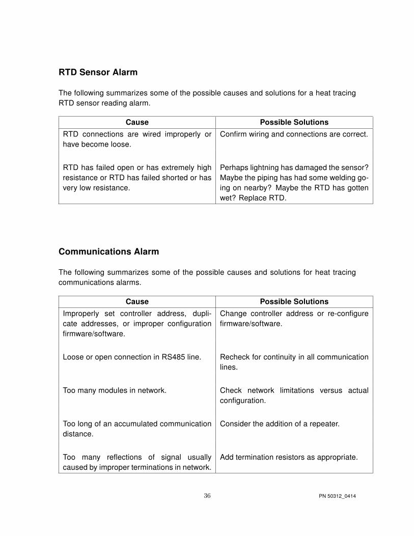
RTD Sensor Alarm
The following summarizes some of the possible causes and solutions for a heat tracingRTD sensor reading alarm.
Cause Possible Solutions
RTD connections are wired improperly orhave become loose.
Confirm wiring and connections are correct.
RTD has failed open or has extremely highresistance or RTD has failed shorted or hasvery low resistance.
Perhaps lightning has damaged the sensor?Maybe the piping has had some welding go-ing on nearby? Maybe the RTD has gottenwet? Replace RTD.
Communications Alarm
The following summarizes some of the possible causes and solutions for heat tracingcommunications alarms.
Cause Possible Solutions
Improperly set controller address, dupli-cate addresses, or improper configurationfirmware/software.
Change controller address or re-configurefirmware/software.
Loose or open connection in RS485 line. Recheck for continuity in all communicationlines.
Too many modules in network. Check network limitations versus actualconfiguration.
Too long of an accumulated communicationdistance.
Consider the addition of a repeater.
Too many reflections of signal usuallycaused by improper terminations in network.
Add termination resistors as appropriate.
36 PN 50312_0414

Circuit Fault Alarm
The following summarizes some of the possible causes and solutions for heat tracingcircuit fault alarms.
Cause Possible Solutions
Upon initial installation start-up, improperwiring of the relay or low current in heater.
Confirm correct wiring and presence of theheater. Where normal operating amperageis in range of 0 to 250mA, disabling theSelf-Test function or adding multiple loopsthrough the current sensing toroid may berequired.
During daily operations; possibly indicatesrelay contact failure.
If relay has failed, replace.
Breaker off. Turn on breaker after conferring with opera-tions manager.
High Current Readings/Alarms
The following summarizes some of the possible causes and solutions for heat tracinghigh current readings or alarms.
Cause Possible Solutions
Self regulating heater or power limitingheater current may exceed set value duringnormal operation or start-up operations.
Increase high current alarm set point (if ap-proved by project engineer). For startup op-eration current alarm nuisances, it may alsobe desirable to increase the delay time (be-fore a current reading is done after turn on)set in the controller.
Self-regulating or power limiting heater maybe operating at cooler than design pipe tem-peratures due to processing conditions andthus heaters may be drawing higher currentvalues.
Increase high current alarm set point (if ap-proved by project engineer).
37 PN 50312_0414

Self-regulating or power limiting heater maybe operating in its cold start regime.
When reading current on one of these typeheaters, it is necessary to read the current atsteady state. One may have to wait as longas 5 minutes for heater steady state values.After five minutes the current value will con-tinue to drop as the pipe or equipment be-gins to warm.
Heater circuit may be longer than antici-pated in the design stage.
Verify installed length (if possible) and if dif-ferent review design. If length is different butperformance-wise the “as built” design is ac-ceptable, initiate “as built” drawing changeand change controller high current setting.
Wrong heater wattage or heater resistancemay be installed.
Check heater set tags or markings on heatercable against installation drawings. As anadditional check, disconnect heater frompower and measure DC resistance.
Heat tracing may be powered on wrong volt-age.
Recheck heater supply voltage.
Current sensing circuitry may have encoun-tered a problem.
Use a different current clamp type meterwhich is known to be accurate and do acomparative reading. Investigate currentmeasurement circuitry further. Note that oneshould only read heater currents when theheater is 100% on.
Field heater wiring is improperly labeledand/or connected such that the heater andthe circuit number are not matched.
Trace out the circuit wiring from the fieldback into the panel and subsequently to thecontroller. Wherever possible, turn the cir-cuit “off” and “on” and watch for an appro-priate response. If this is the problem, re-dothe wiring.
38 PN 50312_0414

Short circuit in a series resistance circuit. Disconnect heater from power, meg be-tween each of the conductors and groundfor proper dielectric rating. If okay, measureresistance of circuit for agreement with de-sign values.
Low Current Readings/Alarms
The following summarizes the possible causes and solutions for heat tracing low currentreadings/alarms.
Cause Possible Solutions
Self-regulating or power limiting heater maybe operating at higher than design pipe tem-peratures due to processing conditions andthus heaters may be drawing lower currentvalues.
Decrease low current alarm setpoint (if ap-proved by project engineer).
Loss of a branch of the heat tracing circuit. Measure total current and each branch cur-rent. Compare to design values. Check allconnections.
Breaker off. Turn breaker back on after conferring withoperations manager.
Heat tracing cable may have been exposedto temperatures in excess of their maxi-mum temperature ratings (excessive steam-out temperatures or upset process temper-ature events) and could have damaged theheater.
Replace heater.
39 PN 50312_0414

Controller may be in error in reading current. Use a different current clamp type meterwhich is known to be accurate and do acomparative reading. If the current mea-suring circuitry is in error, investigate con-trols further. Note that one should only readheater currents when the heater is 100% on.
Heater circuit may be shorter than antici-pated in the design stage.
Verify installed length (if possible) and ifdifferent review design. If length is differ-ent but performance-wise the “as built” de-sign is acceptable, initiate “as built” drawingchange and change controller low currentsetting. Check heater set tags or markingson heater cable against installation draw-ings. As an additional check, disconnectheater from power and measure DC resis-tance.
Wrong heater wattage or heater resistancemay be installed.
Measure pipe temperature and measuresteady-state heater current, voltage, andlength. Compare to manufacturer’s ratedpower curve. Replace heat tracing cable ifnecessary.
Heat tracing may be powered on wrong volt-age.
Recheck heater supply voltage.
Current sensing circuitry may have encoun-tered a problem.
Use a different current clamp type meterwhich is known to be accurate and do acomparative reading. Investigate currentmeasurement circuitry further. Note that oneshould only read heater currents when theheater is 100% on.
Field heater wiring is improperly labeledand/or connected such that the heater andthe circuit number are not matched.
Trace out the circuit wiring from the fieldback into the panel and subsequently to thecontroller. Wherever possible, turn the cir-cuit “off” and “on” and watch for an appro-priate response. If this is the problem, re-dothe wiring.
40 PN 50312_0414

Open circuit in a series resistance circuit. Disconnect heater from power, meg be-tween each of the conductors and groundfor proper dielectric rating. If okay, measureresistance of circuit for agreement with de-sign values.
High Ground Current Alarm
The following summarizes some of the possible causes and solutions for heat tracinghigh ground current alarm.
Cause Possible Solutions
Heat tracing is damaged. Disconnect heat tracing circuit and deter-mine if alarm clears. If so, repair heat trac-ing.
Wiring to heat tracing had high leakage cur-rent.
Disconnect heat tracing and sequentiallydisconnect power wiring until the alarmceases. Check last section removed fordamage.
Improper wiring of current sense wiresthrough toroid.
The current sensing toroid must have theoutgoing heater current lead and the returncurrent heater lead run through the toroidfor a proper ground leakage measurement.Redo wire routing if only one wire has beenrun through the current sensing toroid.
Heat tracing power wires in a multiple circuitsystem improperly paired.
If the return current wire in the toroid is froma different circuit the two heater currentswill not cancel and leave only leakage to bemeasured. Correct wiring.
41 PN 50312_0414

Heat tracing circuit has higher than expectedleakage due to circuit length or higher volt-age.
Replace the EPD breaker with a higherground current trip device if available.Where a controller (with variable leakagetrip functions) is doing the ground leakagedetection function, increase ground leakagealarm set point (if approved by project engi-neer).
If issues remain after exercising all these possible causes and solutions for heat tracingalarms and trips, contact your nearest Thermon engineering center for assistance and/orfor arranging for field service.
42 PN 50312_0414

Pendin
gAppendix B
This Appendix applies to TraceNet TC Series panels without purge equipment. The TCSeries panels have been certified to be in compliance with IEC 60079-0: 2011, IEC60079-15: 2010, EN 60079-0: 2012, and EN 60079-15: 2010.
MARKINGS FOR TC SERIES PANELS
The panels shall be marked IECEx FMG 12.0018X Ex nA IIC T4 Gc, and/or II 3 GEx nA IIC T4 Gc FM13ATEX0073X, along with Ta = -40◦C to +55◦C and IP54.
43 PN 50312_0414

Pendin
g
Appendix C
This Appendix applies to TraceNet TC Series panels with purge equipment. The TCSeries panels have been certified to be in compliance with IEC 60079-0: 2011 and IEC60079-2: 2007.
MARKINGS FOR TC SERIES PANELS
The panels shall be marked IECEx FMG 11.0028X Ex pxb IIC T4 Ta = -20◦C to +50◦C,for Zone 1 applications.
The panel shall be marked IECEx FMG 11.0028X Ex pzc IIC T4 Ta = -20◦C to +55◦C,for Zone 2 applications.
SUPPLY LINES FOR PROTECTIVE GAS
a. The point at which the protective gas enters the supply lines(s) shall be situated in anon-hazardous location.
b. The intake line(s) to a compressor should not pass through a hazardous area. If thecompressor intake line passes through a hazardous area, it should be constructed ofnoncombustible material and protected against mechanical damage and corrosion.
c. The purge duration shall be increased by the time necessary to purge the free volumeof the associated lines (if applicable) which are not a part of the certified panel by at leastfive times their volume at the minimum flow rates (see panel markings) specified by themanufacturer.
POWER FOR PROTECTIVE GAS SUPPLY
The electrical power for the protective gas supply shall be taken from a power sourceseparate from the power source of the panel.
ENCLOSURE MAXIMUM OVERPRESSURE
The purge equipment inlet pressure shall be limited to 120 PSI.
44 PN 50312_0414

Thermon Manufacturing Company100 Thermon DriveSan Marcos Texaswww.thermon.com
Thermon PN 50312_0414