Embed Size (px)
Citation preview

iTELEDYNE ANALYTICAL INSTRUMENTS
OPERATING INSTRUCTIONS FOR
Model 3160Trace Oxygen Analyzer
P/N M52972ECO# 99-0323
08/06/99
HIGHLY TOXIC AND OR FLAMMABLE LIQUIDS OR GASES MAY BE PRESENT IN THIS MONITORING SYSTEM.
PERSONAL PROTECTIVE EQUIPMENT MAY BE REQUIRED WHEN SERVICING THIS SYSTEM.
HAZARDOUS VOLTAGES EXIST ON CERTAIN COMPONENTS INTERNALLY WHICH MAY PERSIST FOR ATIME EVEN AFTER THE POWER IS TURNED OFF AND DISCONNECTED.
ONLY AUTHORIZED PERSONNEL SHOULD CONDUCT MAINTENANCE AND/OR SERVICING. BEFORECONDUCTING ANY MAINTENANCE OR SERVICING CONSULT WITH AUTHORIZED SUPERVISOR/MANAGER.
DANGER
ii TELEDYNE ANALYTICAL INSTRUMENTS
Copyright © 1999 Teledyne Analytical InstrumentsAll Rights Reserved. No part of this manual may be reproduced, transmitted, transcribed, stored in aretrieval system, or translated into any other language or computer language in whole or in part, in anyform or by any means, whether it be electronic, mechanical, magnetic, optical, manual, or otherwise,without the prior written consent of Teledyne Analytical Instruments, 16830 Chestnut Street, City ofIndustry, CA 91749-1580.
Warranty
This equipment is sold subject to the mutual agreement that it is warranted by us free from defects ofmaterial and of construction, and that our liability shall be limited to replacing or repairing at ourfactory (without charge, except for transportation), or at customer plant at our option, any material orconstruction in which defects become apparent within one year from the date of shipment, except incases where quotations or acknowledgements provide for a shorter period. The Micro-Fuel Cellwarranty period begins on the date of shipment from Teledyne. Components manufactured by othersbear the warranty of their manufacturer. This warranty does not cover defects caused by wear, accident,misuse, neglect or repairs other than those performed by Teledyne or an authorized service center. Weassume no liability for direct or indirect damages of any kind and the purchaser by the acceptance ofthe equipment will assume all liability for any damage which may result from its use or misuse.
We reserve the right to employ any suitable material in the manufacture of our apparatus, and to makeany alterations in the dimensions, shape or weight of any parts, in so far as such alterations do notadversely affect our warranty.
Important Notice
This instrument is intended to be used as a tool to gather valuable data. The information provided bythe instrument may assist the user in eliminating potential hazards caused by the process that theinstrument is intended to monitor; however, it is essential that all personnel involved in the use of theit is essential that all personnel involved in the use of theit is essential that all personnel involved in the use of theit is essential that all personnel involved in the use of theit is essential that all personnel involved in the use of theinstrument or its interface with the process being measured be properly trained in the process itself,instrument or its interface with the process being measured be properly trained in the process itself,instrument or its interface with the process being measured be properly trained in the process itself,instrument or its interface with the process being measured be properly trained in the process itself,instrument or its interface with the process being measured be properly trained in the process itself,as well as all instrumentation related to it.as well as all instrumentation related to it.as well as all instrumentation related to it.as well as all instrumentation related to it.as well as all instrumentation related to it.
The safety of personnel is ultimately the responsibility of those who control process conditions. Whilethis instrument may be able to provide early warning of imminent danger, it has no control overprocess conditions, and can be misused. In particular, any alarm or control system installed must betested and understood, both as to how they operate and as to how they can be defeated. Any safeguardsrequired such as locks, labels, or redundancy must be provided by the user or specifically requested ofTeledyne when the order is placed.
The purchaser must be aware of the hazardous conditions inherent in the process(es) he uses. He isresponsible for training his personnel, for providing hazard warning methods and instrumentation perthe appropriate standards, and for ensuring that hazard warning devices and instrumentation aremaintained and operated properly.
Teledyne Analytical Instruments, the manufacturer of this instrument, cannot accept responsibility forconditions beyond its knowledge and control. No statement expressed or implied by this documentNo statement expressed or implied by this documentNo statement expressed or implied by this documentNo statement expressed or implied by this documentNo statement expressed or implied by this documentor any information disseminated by the manufacturer or his agents is to be construed as a warrantyor any information disseminated by the manufacturer or his agents is to be construed as a warrantyor any information disseminated by the manufacturer or his agents is to be construed as a warrantyor any information disseminated by the manufacturer or his agents is to be construed as a warrantyor any information disseminated by the manufacturer or his agents is to be construed as a warrantyof adequate safety control under the user’s process conditions.of adequate safety control under the user’s process conditions.of adequate safety control under the user’s process conditions.of adequate safety control under the user’s process conditions.of adequate safety control under the user’s process conditions.

iiiTELEDYNE ANALYTICAL INSTRUMENTS

iv TELEDYNE ANALYTICAL INSTRUMENTS
TTTTTababababable of Contentsle of Contentsle of Contentsle of Contentsle of Contents
1 Introduction1.1 Features ....................................................................................... 1-1
1.1.1 Fixed Features .............................................................. 1-11.1.2 Variable Features ......................................................... 1-1
1.2 Components ................................................................................. 1-31.3 Options and Model Numbers ........................................................ 1-31.4 Applications ................................................................................. 1-4
2 Operational Theory2.1 Principles of Operation ........................................................... 2-1
2.1.1 Micro-Fuel Cell Sensor ................................................. 2-32.1.2 Sample System .............................................................. 2-32.1.3 Electronics and Signal Processing ............................. 2-5Range Identifier Table ....................................................... 2-7
3 Installation3.1 Unpacking the Analyzer ................................................................ 3-13.2 Front Panel ................................................................................. 3-13.3 Rear Panel ................................................................................... 3-23.4 Gas Line Connections ................................................................... 3-4
3.4.1 Span Gas In .................................................................. 3-43.4.2 Instrument Air ................................................................ 3-43.4.3 Sample Gas In ............................................................... 3-43.4.4 Vent .............................................................................. 3-4
3.5 Micro-Fuel Cell Installation or Replacement .................................. 3-53.6 Electrical Connections ............................................................. 3-6
3.6.1 Voltage Selection .......................................................... 3-73.6.2 Fuse Changing .............................................................. 3-83.6.3 Parallel and Serial Ports .......................................... 3-9
3.7 Installation Checklist ..................................................................... 3-10
4 Operations4.1 Front Panel Controls ..................................................................... 4-1
4.1.1 Spinning Wheel ............................................................. 4-24.1.2 Cell Output Factor ........................................................ 4-2
4.2 Modes of Operation ..................................................................... 4-2Cold Start-Up ........................................................................ 4-5
(continued)

vTELEDYNE ANALYTICAL INSTRUMENTS
TTTTTababababable of Contents (continle of Contents (continle of Contents (continle of Contents (continle of Contents (continued)ued)ued)ued)ued)
Calibration Zeroing ........................................................... 4-6Calibration Using Span Gas .............................................. 4-8Select Active Sensor (Two Cells Only) ............................. 4-11Install Sensor and Test Alternate Sensor .... (Two Cells Only) .. 4-12O
2 Range Set-Up .................................................................. 4-14
Set-up Alarms ........................................................................ 4-15Logger Set-Up ....................................................................... 4-17Set-Up Clock Functions ......................................................... 4-19Changing Passwords For Remote
Monitoring and Control ......................................... 4-21System Statistics ..................................................................... 4-23
5 Maintenance & Troubleshooting5.1 Routine Maintenance .................................................................... 5-1
5.1.1 Sensor Maintenance ............................................... 5-15.1.2 Scrubber Maintenance .................................................. 5-1
5.2 Troubleshooting ............................................................................ 5-2
AppendixA-1 Specifications Sheet ................................................................ A-1A-2 Recommended Spare Parts List .............................................. A-2A-3 Drawing List ........................................................................... A-3A-4 Material Safety Data Sheet ..................................................... A-4A-5 Material Safety Data Sheet ..................................................... A-5

vi TELEDYNE ANALYTICAL INSTRUMENTS

1-1
Introduction 1Introduction 1Introduction 1Introduction 1Introduction 1
TELEDYNE ANALYTICAL INSTRUMENTS
Introduction
1.1 Features
1.1.1 Fixed Features
The Model 3160 is a microprocessor-based trace oxygen monitoring system thatprovides on-line monitoring of trace oxygen at parts-per-million (PPM) levels and candirectly measure the level of purity in high-grade gases.
The 3160 computer uses an Intel® 80188 microprocessor combined with 32kilobytes of random access memory (RAM) and 128 kilobytes of read-only memory(ROM). The total computer program resides in the ROM and is not affected by shut-down periods, loss of power, or battery failure. However, calibration parameters andstored measurement readings are retained in battery-backed-up RAM, which requirecontinuous battery voltage in order to be retained. This information will be lost ifbattery power is interrupted, as in battery replacement.
Two displays help you monitor trace oxygen levels: a red 4-digit light emittingdiode (LED) display with one-inch numerals is easily read at a distance or even inbright daylight, and a liquid crystal display (LCD) helps you keep track of alarmsetpoints, ranges, mode and system statistics.
1.1.2 Variable Features
Various models are available. The following features describe the basic model,but the exact configuration depends on the standard options incorporated. Paragraph1.3 contains a list of standard variations on the basic model.
The Class B-2 Micro-Fuel Cell measures trace O2 in a mixture of gases. Because
the Micro-Fuel Cell sensor is a sealed electrochemical device, it is replaced as a unit.There are no electrolytes to change or electrodes to clean, making the sensor mainte-nance free. The analyzer can be configured with one or two sensor blocks. Each blockcan be isolated by pneumatically switched valves. The software automatically adjustswhen a second cell block is present.

1-2
1 Introduction1 Introduction1 Introduction1 Introduction1 Introduction
TELEDYNE ANALYTICAL INSTRUMENTS
The 3160 features six full-scale linear ranges of analysis:
• 0–1 PPM
• 0–10 PPM
• 0–100 PPM
• 0–1000 PPM
• 0–1%
• 0–25%
An AutoRanging feature automatically selects the range that is appropriate for agiven reading. For example, if the O
2 level exceeds 100% of the current range, the
analyzer switches to the next higher range. When desired, a manual override featureallows a particular range of interest to be locked-in.
With the AutoSpan feature, the analyzer automatically calibrates at scheduledintervals, and automatically performs electronic zeroing and sensor settling detectionduring calibration.
Five user-programmable absolute-reading (PPM) alarm setpoints with assignableForm 1C (SPDT) relays are provided, along with a RS-232C bidirectional serial dataport, and four signal outputs for chart recorders, etc. TheRS-232 serial port can be used with or without a modem to connect with
• a personal computer loaded with the Teledyne Remote AnalyticalControl Software (TRACS)
• any terminal or terminal emulation software
• a custom computer program
Several analyzer functions, including troubleshooting, can be run from your PCthrough the phone line to the analyzer.
The analyzer has separate sample and span gas ports, which allow the installationof an external source of span gas for calibration without interfering with the samplegas line.
An optional scrubber installed into the sample system allows sample gas to beused as a zero gas after treatment with the scrubber. If the scrubber is installed, pneu-matic valves on either side of the scrubber open automatically during zeroing.
Note: Units equipped with a scrubber should only be used with inert gasesand saturated hydrocarbons.
The analyzer output is not affected by minor changes in the flow rate. Analyzerperformance is stable under minor mechanical vibration.

1-3
Introduction 1Introduction 1Introduction 1Introduction 1Introduction 1
TELEDYNE ANALYTICAL INSTRUMENTS
1.2 Components
The analyzer is designed to mount in a standard 19-inch rack. All of the opera-tional controls are easily accessed through the front panel. The analyzer contains eachof the following:
• Analysis Section
• Single or Dual Electrochemical Micro-Fuel Cell
• Sample System
• Power Supply
• Microcontroller Module
• LED Display
The front panel consists of:
• LED Display
• LCD Display with Touch Panel
• Micro-Fuel Cell Access Panel
• Flowmeter and flow set knob
The back panel ports are:
• Gas Inlet/Outlet Ports
• Electrical Connections
1.3 Options and Model Numbers
The 3160 is available with the following standard options, which are designatedby a descriptive suffix on the model number. Most of the options can be combined.
• 3160SA Single fuel cell.
• 3160SB Single fuel cell and oxygen scrubber
• 3160DA Dual fuel cell
• 3160DB Dual fuel cell and oxygen scrubber
• 3160SAS Single cell and stainless steel cell block
• 3160SBS Single cell, stainless steel cell block, and oxygen scrubber
• 3160DAS Dual cell and stainless steel cell block
• 3160DBS Dual cell, stainless steel cell block, and oxygen scrubber

1-4
1 Introduction1 Introduction1 Introduction1 Introduction1 Introduction
TELEDYNE ANALYTICAL INSTRUMENTS
1.4 Applications
The analyzer is an invaluable tool in the following applications and industries:
• Inert and gaseous hydrocarbon stream monitoring.
• Measuring the purity of various gases in air separation plants.
• Prevention of oxidation by measuring the purity of blanketing gases infiber and glass industries.
• Monitoring and controlling gas atmospheres in the heat treatment of metalsin steel and other metal industries.
• Gas analysis and research in laboratories and research and developmentareas.
• Semiconductor manufacturing.
• Process monitoring of gaseous monomers—vinyl chloride, propylene,butadiene, or ethylene.
• Gas purity certification.
• Glove box leak detection.
• Natural gas treatment and transmission.
• Inert gas welding of exotic metals.

Operational Theory 2Operational Theory 2Operational Theory 2Operational Theory 2Operational Theory 2
2-1TELEDYNE ANALYTICAL INSTRUMENTS
Operational Theory
2.1 Principles of Operation
The sub-systems that make up the analyzer are:
1. Micro-Fuel Cell Sensor
2. Sample System
3. Electronic Signal Processing
The Micro-Fuel Cell sensor is an electrochemical galvanic device that translatesthe amount of oxygen present in the sample into an electrical current. The samplesystem delivers the sample gas in a form that is as unaltered as possible for testing,and for leak-free transport of gases through the analyzer.
The electronic signal processing unit (control module) is designed to simplify theoperation of the analyzer and accurately process the signal from various components.The control module incorporates a microprocessor which allows the operation of theanalyzer with a minimum of operator interaction. Figure 2-1 illustrates majorcomponents.

2-2
2 Operational Theory2 Operational Theory2 Operational Theory2 Operational Theory2 Operational Theory
TELEDYNE ANALYTICAL INSTRUMENTS
Figure 2-1. Major Components.
O
I

Operational Theory 2Operational Theory 2Operational Theory 2Operational Theory 2Operational Theory 2
2-3TELEDYNE ANALYTICAL INSTRUMENTS
2.1.1 Micro-Fuel Cell Sensor
The Micro-Fuel Cell is a sealed plastic disposable oxygen transducer that mea-sures 1¼ inches in diameter and is ¾ inch thick. Inside of the cell are a cathode andanode immersed in 15% aqueous KOH electrolyte. At one end of the sensor is aTeflon diffusion membrane; the other end is sealed with a polyethylene membrane. Atthe rear of the cell is a contact plate consisting of two concentric foils. The foils matewith spring-loaded contacts in the sensor block assembly and provide the electricalconnection to the rest of the analyzer.
The sensing cathode, located beneath the diffusion membrane, has a surface areaof 2.48 cm2. The sample gas enters the sensor block through an inlet tube between thecathode and the sensor block cap, diffuses through the Teflon membrane, and anyoxygen in the sample gas is reduced on the surface of the cathode by the followingmechanism:
O2 + 2H2O + 4e––––– → 4OH––––– (cathode)
When the oxygen is reduced at the cathode, lead is simultaneously oxidized at theanode by the following mechanism.
2Pb → 2Pb+2 + 4e––––– (anode)
The electrons released at the surface of the anode flow to the cathode surface viaan external circuit. This current is proportional to the amount of oxygen. It is mea-sured and used to determine the oxygen concentration in the gas mixture.
The overall reaction for the fuel cell is:
2Pb + O2 → 2PbO
The output of the fuel cell is limited by the amount of oxygen in the cell at anyone time, and the amount of stored anode material. In the absence of oxygen, there isno current generated.
2.1.2 Sample System
The sample system delivers gases to the Micro-Fuel Cell sensor from the ana-lyzer rear panel inlet. Depending on the mode of operation either a sample or zero gasis delivered.
The Model 3160 sample system is designed and fabricated to ensure that theoxygen concentration of the gas is not altered as it travels through the sample system.
The following list of sample system and analyzer features are among thoseavailable, but the exact configuration depends on the standard options incorporated.Paragraph 1.3 contains a list of the standard variations on the basic model.

2-4
2 Operational Theory2 Operational Theory2 Operational Theory2 Operational Theory2 Operational Theory
TELEDYNE ANALYTICAL INSTRUMENTS
• Electropolished 316L-type stainless steel components.
To eliminate oxygen absorption and desorption from the internalwetted surfaces of the sample system components, the sample system isfabricated from electropolished 316L-type stainless steel.
• Welding/Metal Gasket-Type Fittings.
All of the joints upstream of the Micro-Fuel Cell oxygen sensor areorbitally welded. Orbital welding is used in the sample systemwherever feasible. Orbital welding fuses the electropolished 316Lstainless steel components together, forming a smooth, clean internal(wetted) weld junction and eliminating small spaces around the weldjunction where gases can get trapped or absorbed. All of the weldjunctions in the entire assembly are purged using an inert gas duringwelding to ensure that there is no oxygen contamination.
Orbital welding is used where practical; otherwise, conventionalprecision welding is used. For example, conventional precision weldingis used to fuse the tubes to the mounting blocks.
• Valves.
The analyzer sampling system utilizes three different types of valves.Each valve is selected to prevent oxygen contamination of the sampledepending on its position and purpose in the circuit.
Air-Actuated Bellows Valves: These valves are normally closed in thesample system. They are used to control the delivery through the samplesystem of the sample or zero gas. The valve bodies are orbitally welded inthe system and the valve bonnets make a metal-to-metal seal to the body.This valve system eliminates inboard and outboard gas leakage. The valvesare activated (open/closed) by computer-controlled solenoid valves.
Metering Valve: The metering valve is used to manually control thegas flow rate to the sensor. The body of the metering valve is orbitallywelded, and the bonnet is sealed to the body with metal O-rings. This type ofvalve eliminates inboard and outboard gas leakage.
Solenoid Valves: The solenoid valves control the air flow to the air-activated bellows valves. The solenoid valves are controlled by themicroprocessor module. When de-energized, the valve outlet is open toambient air, allowing the air-activated bellows valve to close.
• Scrubber (optional). See Appendix for details.
In systems with a scrubber, oxygen-trapping media is used to removeany trace oxygen from the sample gas. This occurs automatically in thezero menu, where the pneumatic valves leading to the scrubber aretriggered by a certain menu sequence. This process enables sample gas

Operational Theory 2Operational Theory 2Operational Theory 2Operational Theory 2Operational Theory 2
2-5TELEDYNE ANALYTICAL INSTRUMENTS
to be used to zero the analyzer, eliminating the need to switch externaltanks.
• Overall Design.
The design of the sample system minimizes the volume of dead space, whichcan retain residual gas from another route or previous mode of analysis.
Figure 2-2: Model 3160 flow schematic.
2.1.3 Electronics and Signal Processing
The Model 3160 analyzer has an embedded microcomputer, which controls allsignal processing, input/output, and display functions for the analyzer. System poweris supplied from a power supply module designed to be compatible with any interna-tional power source.
The microcomputer, a liquid crystal display (LCD), and all analog signal pro-cessing electronics are located inside a replaceable control module. A light emittingdiode (LED) display is located outside the control module.

2-6
2 Operational Theory2 Operational Theory2 Operational Theory2 Operational Theory2 Operational Theory
TELEDYNE ANALYTICAL INSTRUMENTS
Electronics in the analyzer are grouped according to function:
1. Analog in
2. Analog out
3. Digital circuit
4. Power supply
Analog signal processing is accomplished in two plug-in circuit cards operatingunder control of the microcomputer. All analog signals are converted to digital earlyin the processing cycle to minimize analog processing and assure maximum systemaccuracy, since digital processing is much more accurate than analog and immune tomany parameters such as drift and aging.
The initial processing and digitization of the signal from the Micro-Fuel Celltakes place on two circuit boards: the six-decade programmable printed circuit board(PCB), and the analog input board.
The first step in the chain takes place on the six-decade programmable PCB,which is mounted directly on top of the cell block. The output of the sensor is acurrent that is linearly proportional to the oxygen concentration. At low concentra-tions, the current from the sensor is low, which makes the close physical proximity ofthe pre-amp circuitry to the Micro-Fuel Cell necessary.
The sensor current is routed into a low-offset, low-bias current operationalamplifier configured as a current-to-voltage converter. The signal is sent through twoamplifiers to the analog input board. The pre-amp board provides sensor zeroing and aconnection to the thermistor in the sensor cell block.
The analog input PCB, which plugs into a DIN connector on the digital PCB,performs three functions:
• Temperature compensation in the sensor signal
• Sensor offset correction
• Digitization
A thermistor inside the sensor block registers resistance and thus the temperatureof the sensor. Accordingly, an analog-to-digital converter configured as a digitally-programmed attenuator (DPA) is used to reduce or increase the gain of the sensorsignal, so that the signal coming out of the DPA is independent of temperature.
If the software determines that the sensor needs offsetting, the sensor current isback-calculated and an analog-to-digital converter on the analog board is driven by thesoftware to produce a voltage that is used to force a current into the current-to-voltageconverter located on the pre-amp board. The current injected is equal and opposite inpolarity to the portion of the sensor current that needs offsetting.
Digitization is provided by a 12-bit analog-to-digital converter, which digitizesthe oxygen and temperature signals.
Operational Theory 2Operational Theory 2Operational Theory 2Operational Theory 2Operational Theory 2
2-7TELEDYNE ANALYTICAL INSTRUMENTS
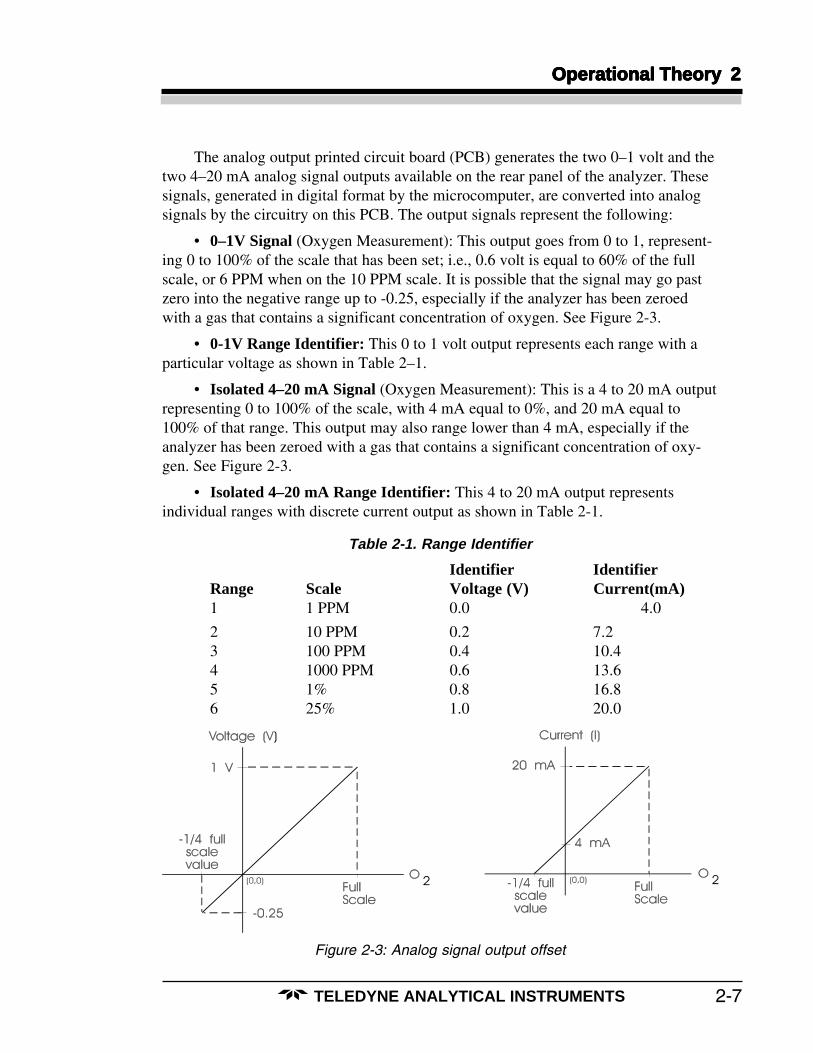
The analog output printed circuit board (PCB) generates the two 0–1 volt and thetwo 4–20 mA analog signal outputs available on the rear panel of the analyzer. Thesesignals, generated in digital format by the microcomputer, are converted into analogsignals by the circuitry on this PCB. The output signals represent the following:
• 0–1V Signal (Oxygen Measurement): This output goes from 0 to 1, represent-ing 0 to 100% of the scale that has been set; i.e., 0.6 volt is equal to 60% of the fullscale, or 6 PPM when on the 10 PPM scale. It is possible that the signal may go pastzero into the negative range up to -0.25, especially if the analyzer has been zeroedwith a gas that contains a significant concentration of oxygen. See Figure 2-3.
• 0-1V Range Identifier: This 0 to 1 volt output represents each range with aparticular voltage as shown in Table 2–1.
• Isolated 4–20 mA Signal (Oxygen Measurement): This is a 4 to 20 mA outputrepresenting 0 to 100% of the scale, with 4 mA equal to 0%, and 20 mA equal to100% of that range. This output may also range lower than 4 mA, especially if theanalyzer has been zeroed with a gas that contains a significant concentration of oxy-gen. See Figure 2-3.
• Isolated 4–20 mA Range Identifier: This 4 to 20 mA output representsindividual ranges with discrete current output as shown in Table 2-1.
Table 2-1. Range Identifier
Identifier IdentifierRange Scale Voltage (V) Current(mA)1 1 PPM 0.0 4.0
2 10 PPM 0.2 7.23 100 PPM 0.4 10.44 1000 PPM 0.6 13.65 1% 0.8 16.86 25% 1.0 20.0
Figure 2-3: Analog signal output offset

2-8
2 Operational Theory2 Operational Theory2 Operational Theory2 Operational Theory2 Operational Theory
TELEDYNE ANALYTICAL INSTRUMENTS
The digital printed circuit board (PCB) is a general purpose microcomputer usedto control all functions of the analyzer. The analog input PCB and the analog outputPCB plug directly into connectors located on the digital PCB. In addition to control-ling these analog PCBs, the digital board performs the following functions:
1. Processes input from the control panel pushbuttons.
2. Provides signals for the selectable alarms.
3. Processes serial I/O functions (RS-232 data). The serial interface defaultand programmable parameters are listed in Table 2-2.
Table 2-2. Default and Programmable Parameters
Defaults Programmable Options
1200 Baud 1200 Baud
8 Bits 5, 6, 7, or 8 Bits
No Parity Even, Odd, or No Parity
1 Stop Bit 1 or 2 Stop Bits
4. Controls the LCD and the LED displays.
LCD: This screen is a dot-matrix display located on the control module ofthe analyzer. It is the user interface for system operations. Itdisplays the menus and command options available for eachfunction.
LED: This screen is a 7-segment display located on the front panel of theanalyzer, above the control module. It displays only the oxygenconcentration. It is large and bright to allow the operator to read itat a greater distance. A dimmer switch for this display is located onthe display PCB behind the front panel.
The analyzer power supply module is a replaceable assembly containing fourpower supplies and five alarm relays. Electronic circuitry used to drive and interfacethe alarm relays to the output of the microcomputer is also located inside this module.
Note: This power supply contains an International Power Entry Module. Thisfeature allows operation on any of four international voltage ranges:100V, 120V, 220V or 240V (50Hz or 60Hz). It also facilitates both NorthAmerican and European fusing arrangements. Programming this mod-ule is described in the installation section of this manual.

Installation 3Installation 3Installation 3Installation 3Installation 3
3-1TELEDYNE ANALYTICAL INSTRUMENTS
Installation
Installation of the analyzer includes:
1. Unpacking the system.
2. Recognizing the necessary precautions when installing the system.
3. Hooking up the sample/span gas and air supply to appropriate connections.
4. Installing the Micro-Fuel Cell sensor(s).
5. Hooking up electrical connections.
6. Testing the system.
3.1 Unpacking the Analyzer
The analyzer is shipped with all the materials and special items you need to installand prepare the system for operation. Carefully unpack the analyzer and inspect it fordamage. Immediately report any damage to the shipping agent. Remove the packingslip and verify that you have received all the components listed in Table 3-1.
Table 3-1. Accessory Kit for Model 3160
QtyQtyQtyQtyQty Part No.Part No.Part No.Part No.Part No. DescriptionDescriptionDescriptionDescriptionDescription3 G285 Weld glands, VCR-type3 G284 Gaskets, VCR-type3 N284 Nuts, female (Hoke 4NM316)2 W64 Wrench, Open End, 3/4"–5/8"1 M52973 Instruction Manual
3.2 Front Panel
The Model 3160 front and rear panels are illustrated in Figure 3–1 on the follow-ing page. The front panel contains the following displays and controls:
1. Main power switch.
2. Light Emitting Diode (LED) display: the O2 concentration is displayed in
bold lettering.

3-2
3 Installation3 Installation3 Installation3 Installation3 Installation
TELEDYNE ANALYTICAL INSTRUMENTS
3. Parts Per Million (PPM) and Percent Oxygen indicators: the PPM light willlight while the instrument is measuring O
2 in units of PPM. The percent
light will light while the instrument is measuring O2 concentration in
percent.
4. Flow Indicator and Flow Set: a flowmeter and flow set knob are providedfor adjusting gas flow in standard cubic feet per hour (SCFH).
5. Liquid Crystal Display (LCD) with keypad: the LCD shows system menusand data during instrument operation. The keypad is the primary user-inputdevice used to enter information in the system.
3.3 Rear Panel
Figure 3–1 also shows the rear panel of the 3160. Located on the rear panel arethe following electrical power and gas input ports, alarm relay outputs, and analog anddigital outputs:
1. Gas Input/Vent: three input fittings are provided for span gas, samplegas, and compressed air for pneumatic valve operation. A single vent is usedfor the sample and span gas outlet. Consult the Appendix for scrubber selec-tion.
2. AC Power Input: 110, 120, 220 or 240 V ~ at 50/60 Hz 1.5 A MAX.
Use 250 V 1.6 A T Fuse for 110, 120 V ~
Use 250 V 0.8 A T Fuse for 220, 240 V ~
3. Alarm Circuit Connections: there are five contact closures/openingsprovided for external alarms. The alarm functions are defined by the user viakeypad input within the LCD menu system.
4. Analog Outputs: four analog output connectors are provided for usewith a chart recorder. Two provide range and data in voltages; the other twoprovide range and data for current-driven recorders.
5. RS-232 Serial Port: a 9–pin digital input/output connector is providedfor connecting either a serial printer or a serial link to an external computer.Optional serial link software (such as TRACS) can be used with the instru-ment for remote external computer monitoring and control of the instrument,via modem or hardware link.

Installation 3Installation 3Installation 3Installation 3Installation 3
3-3TELEDYNE ANALYTICAL INSTRUMENTS
Figure 3–1: Analyzer front and rear panels.
LEDDISPLAY
PPMINDICATOR
PERCENTINDICATOR
LIQUIDCRYSTALDISPLAY
(LCD)
POWERSWITCH
COMPUTERMODULE KEYPAD
FLOWSET
KNOB
FLOWMETER
SENSORACCESSPANEL
REMOVABLETOP COVER
RS-232SERIAL PORT
ANALOGOUTPUT
CONNECTIONS
INSTRUMENTAIR
SPANGAS IN
SAMPLE IN
SAMPLE/SPANVENT
AC POWERVOLTAGE SELECT
ALARMCIRCUIT
CONNECTIONS
������
����
�����
�����
�����
�� �
�� �
����
������
���
��
����
�� �
��
I
O
DIMENSIONS: Inmm

3-4
3 Installation3 Installation3 Installation3 Installation3 Installation
TELEDYNE ANALYTICAL INSTRUMENTS
3.4 Gas Line Connections
All of the gas lines to the system hook up at the back of the unit (see Figure 3–1).All of the fittings on the removable back panel are ¼ " male VCR type fittings, with theexception of the compressed air inlet fitting. Use the wrenches provided to connect thegas lines. Insert the gasket between the fitting and tighten the female and male nutsuntil finger-tight; then, by holding the male nut with the wrench, tighten the female nutwith the second wrench by ¼ turn.
CAUTION: Do not put any torque on the tubes welded on the samplingsystem.
Check that each of the lines is hooked up to the correct connection. The linesshould be connected in the following order (from left to right):
3.4.1. Span Gas In
Provide at least one sample gas of a known oxygen concentration. Using70-99 % of the range just one range above the range of interest is recommended. Anyrange EXCEPT 0-1 ppm may be used to calibrate.
3.4.2. Instrument Air (Compressed Air Fitting)
The gas pressure (70–80 psi) needed to operate the pneumatic valves in theanalyzer can be supplied through this fitting.
CAUTION: Pressure higher than 80 psig can damage the solenoidvalves.
3.4.3. Sample Gas In
Hook up the sample gas to the sample gas inlet. When the sample gas flowsthrough the optional oxygen scrubber, the sample gas becomes the zero gas and can beused for calibration.
Note: Sample and span gas pressure should be between 5 and 10 psig andwithin ±2 psi of each other. A substantial difference in the span andsample gas pressures will cause a sudden change in gas flow rate.
3.4.4. Vent
The vent transports the sample or span gas out of the system after exposure tothe Micro-Fuel Cell sensor.

Installation 3Installation 3Installation 3Installation 3Installation 3
3-5TELEDYNE ANALYTICAL INSTRUMENTS
Figure 3-2: Sensor Installation.
3.5 Micro-Fuel Cell Sensor Installation or Replacement
The 3160 comes with the Micro-Fuel Cell(s) already installed. When installing orreplacing the cells, remember to inspect the replacement sensor for leaks or damage. SeeFigure 3-2.

3-6
3 Installation3 Installation3 Installation3 Installation3 Installation
TELEDYNE ANALYTICAL INSTRUMENTS
1. The sensor compartment is located in the lower right-hand corner of theanalyzer front panel. To remove the sensor compartment panel, loosen thethumbscrews located left and right center of the panel.
2. Make sure that sample gas is flowing through the analyzer, then shut offthe flow completely. This insures that air does not diffuse into the analyzer.
3. Inside the compartment should be two (one) stainless steel cylindricalsensor block(s), each with a clamp lever across the front. The bottom halfof the clamp face is bent outward. To release the clamp, pull the clamplever up and toward you slowly.
4. Releasing the clamp releases the stainless steel block cap on the bottom ofthe sensor block. Pull the cap downward to remove it. There is a guide pinto the rear of the sensor block that aligns the cap to the block.
Note: It is important to minimize the amount of time that the new cell is ex-posed to air in order to reduce the time required for the reading to dropto zero.
5. Remove the Micro-Fuel Cell from the plastic bag. The cell has a meshscreen with a raised plastic dress ring on one side and flat gold contactrings on the other. Place the screen side of the cell face down on the blockcap so that the dress ring locks onto the cap ridges and will not move sideto side. The gold contact rings will be facing up.
6. Carefully guide the sensor and cap into the block, putting the guide pinthrough the hole in the back edge of the cap.
7. While holding the cap in place, squeeze the clamp down firmly until thenotches on the clamp lock onto the block side pins.
8. Immediately start the sample flow, and set to about 2 SCFH. The analyzernow needs to be zeroed and calibrated.
3.6 Electrical Connections
All of the electrical connections are located on the analyzer back panel. Theanalyzer is shipped with all of the electrical connections intact, with no assembly orinstallation required. The power cord receptacle is located in the lower center of thepanel. The voltage selection terminal and the fuse block are in the same fitting directlyabove the power cord receptacle. There are four output signal connectors with screwterminals in the upper right-hand panel. There are two wires per output with the polari-ty noted below each. The five alarm circuit connectors, located in the lower centerright-hand panel, are screw terminals for alarm relay contacts. These five provide a setof Form C contacts for the user. The contacts are capable of switching up to 3 am-peres at 115 V ac into a resistive load.

Installation 3Installation 3Installation 3Installation 3Installation 3
3-7TELEDYNE ANALYTICAL INSTRUMENTS
Figure 3-3: 3160 Rear Panel.
3.6.1 Voltage Selection
WARNING: Power cord must be disconnected before performing any voltageselection!
The voltage setting and fuses of the analyzer can be changed to internationalstandards. To change the voltage setting or fuses:
1. Open the cover using a small blade screwdriver.
2. Remove the cover and the fuse block assembly.
3. Pull the voltage selector card straight out of the housing by pulling on theindicator pin (see Figure 3–4).

3-8
3 Installation3 Installation3 Installation3 Installation3 Installation
TELEDYNE ANALYTICAL INSTRUMENTS
Figure 3-4: Removing the Voltage Card
4. Turn the card so that the desired voltage can be read at the bottom.
5. Slide the indicator pin around the card so that it is pointing up when thevoltage is read at the bottom (see Figure 3–5).
Figure 3–5: Voltage Selection
6. Place the voltage selector card back into the housing. The edge where thedesired voltage is printed should go in first and the printed side of the cardshould be facing the IEC connector.
7. Replace the fuse block and the cover. Verify that the indicator pin ispointing to the correct voltage.
3.6.2 Fuse Changing
NOTE: Spare fuses are located in a clip attached to the power supply enclosureinside of the analyzer.

Installation 3Installation 3Installation 3Installation 3Installation 3
3-9TELEDYNE ANALYTICAL INSTRUMENTS
WARNING: Power cord must be disconnected before performing anyvoltage selection!
To change from North American to European fuses, perform the following:
1. Use a small blade screwdriver to open the cover.
2. Loosen the Phillips screw two turns and remove the fuse block by sliding itaway from the screw and up from the pedestal.
3. Remove the North American fuse and turn the fuse block over.
4. Replace the fuse with European fuses. Two European fuses are required,but the lower one may be replaced with a dummy fuse, or jumper bar (seeFigure 3–6).
Figure 3–6: Fuse Replacement
5. Slide the fuse block back on the Phillips screw and pedestal.
6. Tighten the Phillips screw and replace the cover.
NOTE: The fuses that go into the housing first are the active set.
European 1.6 Amp T Fuses5 x 20 mm
North American 3 A T Fuses

3-10
3 Installation3 Installation3 Installation3 Installation3 Installation
TELEDYNE ANALYTICAL INSTRUMENTS
3.6.3 RS-232 Serial Digital Port
The RS-232 port is configured as data terminal equipment (DTE) and uses a 9-pinD connector wired as follows:
1. No connection2. Transmit Data3. Receive Data4. N/C5. Ground6. N/C7. RTC8. CTS9. N/C
Connecting the analyzer to a modem requires a PC to modem cable. When con-necting the analyzer directly to a PC, terminal or other data terminal equipment, a“null-modem” cable is required.
The following serial interface default parameters are used:
Defaults Programmable Options
1200 Baud 1200 Baud
8 Bits 5, 6, 7, or 8 Bits
No Parity Even, Odd, or None
1 Stop Bit 1 or 2 Stop Bits
3.7 Installation Checklist
Have you:
• Checked for leaks from any of the rear panel connections?
• Checked the sample and span gas pressures (5–10 psi)?
• Checked the instrument air pressure (70–80 psi)?

Operations 4Operations 4Operations 4Operations 4Operations 4
4-1TELEDYNE ANALYTICAL INSTRUMENTS
Operations
4.1 Front Panel Controls
The front panel of the analyzer, shown in Figure 4-1, contains indicators and displaysthrough which the computer module can be accessed. The upper left-hand side of the panelhas an LED screen that displays the oxygen content of the sample in one-inch highnumerals. This display can be brightened or dimmed by a potentiometer located directlybehind the panel inside of the analyzer case. To access it, remove the top cover of theanalyzer.
Figure 4.1: Analyzer front panel.
Below the LED screen are two red LED lights. Each will light to indicate whether theoxygen is being displayed in parts per million (PPM) or percent (%).
To the right of the LED screen is a flowmeter in standard cubic feet per hour(SCFH). The flow set knob adjusts the flow rate of the gas during calibration and zeroing.
In the panel below the LED screen is the LCD display. The five colored buttonsbelow it are used to interface with the computer module in selecting modes, with the LCD
4-2
4 Operations4 Operations4 Operations4 Operations4 Operations
TELEDYNE ANALYTICAL INSTRUMENTS
displaying the function of each button directly above it. The LCD screen displays thecurrent mode and any warning messages, instructions and button functions.
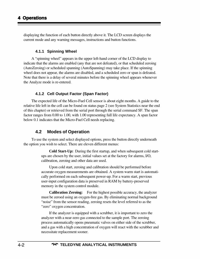
4.1.1 Spinning Wheel
A “spinning wheel” appears in the upper left-hand corner of the LCD display toindicate that the alarms are enabled (any that are not defeated), or that scheduled zeroing(AutoZeroing) or scheduled spanning (AutoSpanning) may take place. If the spinningwheel does not appear, the alarms are disabled, and a scheduled zero or span is defeated.Note that there is a delay of several minutes before the spinning wheel appears wheneverthe Analyze mode is re-entered.
4.1.2 Cell Output Factor (Span Factor)
The expected life of the Micro-Fuel Cell sensor is about eight months. A guide to therelative life left in the cell can be found on status page 2 (see System Statistics near the endof this chapter) or retrieved from the serial port through the serial command SF. The spanfactor ranges from 0.00 to 1.00, with 1.00 representing full life expectancy. A span factorbelow 0.1 indicates that the Micro-Fuel Cell needs replacing.
4.2 Modes of Operation
To use the system and select displayed options, press the button directly underneaththe option you wish to select. There are eleven different menus:
Cold Start-Up: During the first startup, and when subsequent cold start-ups are chosen by the user, initial values set at the factory for alarms, I/O,calibration, zeroing and other data are used.
Upon cold start, zeroing and calibration should be performed beforeaccurate oxygen measurements are obtained. A system warm start is automati-cally performed on each subsequent power-up. For a warm start, previoususer-input configuration data is preserved in RAM by battery-preservedmemory in the system control module.
Calibration Zeroing: For the highest possible accuracy, the analyzermust be zeroed using an oxygen-free gas. By eliminating normal background“noise” from the sensor reading, zeroing resets the level referred to as the“zero” oxygen concentration.
If the analyzer is equipped with a scrubber, it is important to zero theanalyzer with a near-zero gas connected to the sample port. The zeroingprocess automatically opens pneumatic valves on either side of the scrubber,and a gas with a high concentration of oxygen will react with the scrubber andnecessitate replacement sooner.
Operations 4Operations 4Operations 4Operations 4Operations 4
4-3TELEDYNE ANALYTICAL INSTRUMENTS
When waiting for manual sensor settling during calibration zeroing, waituntil the oxygen concentration has reached its lowest value and has remainedso for 10–15 minutes. It is important to make sure that the sensor is reading thelowest possible value, since zeroing will reset the point at which the sensorreads zero. Do not zero prior to reaching the lowest possible oxygen concentra-tion. When initially installing the sensor(s), do a zero calibration, then a spancalibration. If desired, the instrument may be programmed for automaticperiodic zeroing (AutoZeroing) if the optional scrubber is installed. AutoZero-ing uses the scrubber to generate a zero gas from a low O
2 sample gas.
NOTE: 1. Zeroing in the 0-1 PPM range preserves the life of the scrubber.
In scheduled zeroing and spanning (AutoZeroing and AutoSpanning), atime interval must be chosen. This interval determines how often the instru-ment zeros or spans itself. To change the scheduled time, edit it after settingthe interval in the Set Up Clock Functions mode.
NOTE: 2. AutoZeroing and AutoSpanning may be delayed until the alarms have beenenabled.
Calibration Using Span Gas: After zeroing, the instrument can nowbe calibrated using a span gas with a known oxygen concentration. The analyz-er may be calibrated on any range other than 0–1 PPM, but it is best to cali-brate one range up from the range where the sample is expected to be. Thespan gas concentration should be within 70% to 99% of full scale of the rangeselected.
NOTE: 3. Prior to calibration, allow the analyzer reading to come to a stable value withzero or sample gas flowing through the analyzer.
Select Active Sensor (Two cell blocks only): One or two O2 sensor
blocks can be installed in the system. In dual sensor systems, either sensor canbe isolated with pneumatic valves, and the other sensor chosen as the activesensor for O
2 measurements. The system software is aware of how many
sensor blocks are present, but will not automatically switch sensors should onefail.
This menu will not appear if only one cell block is installed.
Install Sensor and Test Alternate Sensor (Two cell blocks only): Pro-cedures are provided for installing a new sensor and for testing the alternate O
2
sensor.
This menu will not appear if only one cell block is installed.
O2 Range Set-Up: The measurement range may be manually chosen, or
the system may be set to automatically choose the range (AutoRanging). In theAutoRanging mode, the range will step up at greater than 100% and stepdown at 80% of full scale of the current range. The analyzer is programmed toprevent oscillation between ranges during rapidly changing oxygen levels.

4-4
4 Operations4 Operations4 Operations4 Operations4 Operations
TELEDYNE ANALYTICAL INSTRUMENTS
Set-Up Alarms: Each of five alarms provided may be programmed toactuate at any O
2 trace level above or below a threshold. The fifth alarm may
also be programmed as a system alarm to monitor several system-level condi-tions. The system alarm can be triggered by the following system operations:
• Scheduled zero (AutoZero) failure
• Scheduled span (AutoSpan) failure
• Battery failure
• Internal errors
Any condition triggering the system alarm can be determined from statuspage 4 (see this chapter: System Statistics).
When the alarms are disabled, scheduled zeroing or spanning will nottake place.
Logger Set-Up: A system data logger keeps a record of past oxygenmeasurements. The logger is presented in the form of a graphed chart on thesystem LCD; gaps in time will not display, and all points shown on a singlechart have the same range and sensor number.
The logger will not record in the Test Alternate Sensor mode.
Set Up Clock Functions: An internal clock provides the time and datefor events scheduled by the user. The internal clock is also used by the loggerto record events scheduled at timed intervals.
Scheduled zeroing and spanning (AutoZeroing and AutoSpanning) are setin this mode. The mode uses an electronic timer to set off the zeroing orspanning sequence at pre-selected intervals. During an AutoZero or AutoSpan,the alarms are defeated and the screen displays “PLEASE WAIT. SCHED-ULED SPAN IN PROGRESS.”
Since AutoZeroing and AutoSpanning uses automatic settling detectionof the sensor, which can take up to fifteen minutes, oxygen monitoring will beinterrupted for the length of time it takes to zero or span, after which monitor-ing will resume. The LCD will display the current background level duringzeroing or spanning.
Changing Passwords For Remote Monitoring and Control:Programmable security passwords are provided to prevent unauthorized accessto remote monitoring and control. “Monitor” is the lowest authorization leveland only permits monitoring of analyzer functions, while “Control” allowsremote control of any function.
System Statistics: Menu screens are available to view various systemparameters, and for setting serial link operation parameters, including modemoperation.

4-5
Operations 4Operations 4Operations 4Operations 4Operations 4
TELEDYNE ANALYTICAL INSTRUMENTS
1. A cold start will automatically occur the first time youstart the analyzer. In any other situation, you can coldstart by turning the analyzer off and holding down thered key below the LCD screen while you turn the powerback on. Continue to hold the red key until the screencomes on. There will be a two minute wait for systeminitialization before the second screen.A warm start will take you directly to step 5.
2. Set the time using the SELEC, UP and DOWN keys,and press ACCPT.
3. Select sensor A or B as the active sensor.(This menu is omitted if only one cell block is installed.)
4. If you have not done so, connect the sample gas to thesample port and press ACK.
5. Using the valve and meter on the sample gas supply, setthe flow rate to 2 SCFH and press ACK.
If you have warm-started, this is the second screen youwill see.
6. The main Analyze mode menu will appear, and themeasured O
2 level of the sample gas will display. The
system should first be zeroed, then spanned, to obtainthe most accurate O
2 measurements.
Cold Start-UpCold Start-UpCold Start-UpCold Start-UpCold Start-Up

4-6
4 Operations4 Operations4 Operations4 Operations4 Operations
TELEDYNE ANALYTICAL INSTRUMENTS
1. At the main Analyze mode screen press ZERO.
2. Press ACK to acknowledge that a low O2 gas has al-
ready been connected to the sample port. The samplegas O
2 level should be close to zero to preserve the life
of the scrubber (if one is installed).
3. Set the flow rate to 2 SCFH using the knob on the sys-tem front panel and press ACK.
4. Press AUTO to let the system determine the settlingtime before spanning or press MAN for manual.
5. If MAN was chosen in step 4, watch the logger or theO
2 value on the screen to assess when the output is con-
stant, and then press ACK.
6. After step 5, the system will automatically span to theuser-entered span value. If the zeroing is successful, themain Analyze mode menu will appear as in step 10.
Calibration ZeroingCalibration ZeroingCalibration ZeroingCalibration ZeroingCalibration Zeroing

4-7
Operations 4Operations 4Operations 4Operations 4Operations 4
TELEDYNE ANALYTICAL INSTRUMENTS
7. If the O2 cell current is too large to be zeroed, an error
message will appear. Press ACK to retry or ESC toabort the zeroing process.
8. If AUTO was chosen in step 4, wait for the O2 level to
settle before the system zeros. This may take from thirty(30) seconds to fifteen (15) minutes, depending on thesample gas oxygen level.
9. After a stable low oxygen level is detected by the sys-tem, the system will automatically zero.
If the O2 cell current is too large to be zeroed, an error
message will appear (see step 7). You will then have topress ESC to abort, or ACK to retry.
10. If the zero is successful, the system will return to themain Analyzer mode menu.

4-8
4 Operations4 Operations4 Operations4 Operations4 Operations
TELEDYNE ANALYTICAL INSTRUMENTS
1. Enter the Calibration mode from the Analyze mode bypressing SPAN.
2. Press ACK if zeroing has already been done. Make sureto zero before calibrating to ensure correct O
2 readings.
3. If the span gas tank is not connected to the span port,connect it now and press ACK.
4. Enter the span gas concentration using the UP andDOWN keys, and press ACCPT.
5. Set the flow rate to 2 SCFH and press ACK.
6. Select manual or automatic sensor settling detection bypressing MAN or AUTO. Automatic sensor settling de-tection lets the system determine when the sensor hasstabilized.
Calibration Using Span GasCalibration Using Span GasCalibration Using Span GasCalibration Using Span GasCalibration Using Span Gas

4-9
Operations 4Operations 4Operations 4Operations 4Operations 4
TELEDYNE ANALYTICAL INSTRUMENTS
7. If AUTO was chosen in step 6, wait for the O2 level to
settle before the system spans. This may take from fif-teen (15) to thirty (30) minutes or longer, depending onthe sample gas oxygen level.
Go to step 11 if MAN was chosen in step 6.
8. If any key was pressed in step 7, the screen indicatesthat the span has been aborted. Press ACK to retryspanning, or ESC to abort the span.
9. After the system has automatically detected sensor sta-bility, the system will automatically span. If the systemspans correctly, the next screen will be the Analyzemode main menu (see step 14).
10. If the O2 cell current is too strong or too weak to be
spanned, an error message will appear. Insure that thespan gas concentration has been entered correctly. PressACK to retry, or ESC to abort the span.
11. If MAN was pressed in step 6, watch the logger or theO
2 value on the screen to determine when the output is
constant, and then press ACK.
12. After step 11, the system will automatically span to theuser-entered span value.

4-10
4 Operations4 Operations4 Operations4 Operations4 Operations
TELEDYNE ANALYTICAL INSTRUMENTS
13. If the O2 cell current is too strong or too weak to span,
an error message will appear. This will not occur if theuser-entered span gas concentration is correct. PressACK to retry, or ESC to abort the span.
14. If the span is successful, the system will return the mainAnalyze mode menu. Check to see that the span value iscorrect.

4-11
Operations 4Operations 4Operations 4Operations 4Operations 4
TELEDYNE ANALYTICAL INSTRUMENTS
1. Enter set-up from the Analyze mode main menu bypressing SETUP.If only one cell block is installed, the TEST and INSTLoptions on the next screen are omitted.
2. Press SET to change the active sensor.
3. Enter your authorization code by using the SELEC, UPand DOWN keys, and press ACCPT.
4. Press SENSR. (This option will not appear if only onesensor block is installed.)
5. Select sensor A or B.
6. The main Analyze mode menu will appear, and will indi-cate the chosen sensor.
Select Active Sensor (TSelect Active Sensor (TSelect Active Sensor (TSelect Active Sensor (TSelect Active Sensor (Twwwwwo Cells Onlo Cells Onlo Cells Onlo Cells Onlo Cells Only)y)y)y)y)

4-12
4 Operations4 Operations4 Operations4 Operations4 Operations
TELEDYNE ANALYTICAL INSTRUMENTS
1. Enter set-up from the Analyze mode by pressingSETUP.If only one cell is installed, the TEST and INSTL op-tions on the next screen are omitted.
2. Press TEST to test the alternate sensor or INSTL to in-stall a new sensor.
3. If TEST was chosen in step 2, the active sensor is dis-played and you are directed to press ACK to test the al-ternate sensor.
If INSTL was chosen in step 2, go to step 5.
4. After pressing ACK in step 3, the alternate sensor isflushed for 10 minutes while the measured O
2 level is
displayed. The 10 minute flush may be restarted bypressing RESET, or aborted by pressing SKIP. Go tostep 8.
5. If INSTL was chosen in step 3, the screen will displaythe active sensor. Press A or B for the sensor you areinstalling.
6. Install the sensor (either A or B from step 5) into thesensor block within two minutes, and press ACK.
Install Sensor and Install Sensor and Install Sensor and Install Sensor and Install Sensor and TTTTTest Alternate Sensor (Test Alternate Sensor (Test Alternate Sensor (Test Alternate Sensor (Test Alternate Sensor (Twwwwwo Cells Onlo Cells Onlo Cells Onlo Cells Onlo Cells Only)y)y)y)y)
4-13
Operations 4Operations 4Operations 4Operations 4Operations 4
TELEDYNE ANALYTICAL INSTRUMENTS
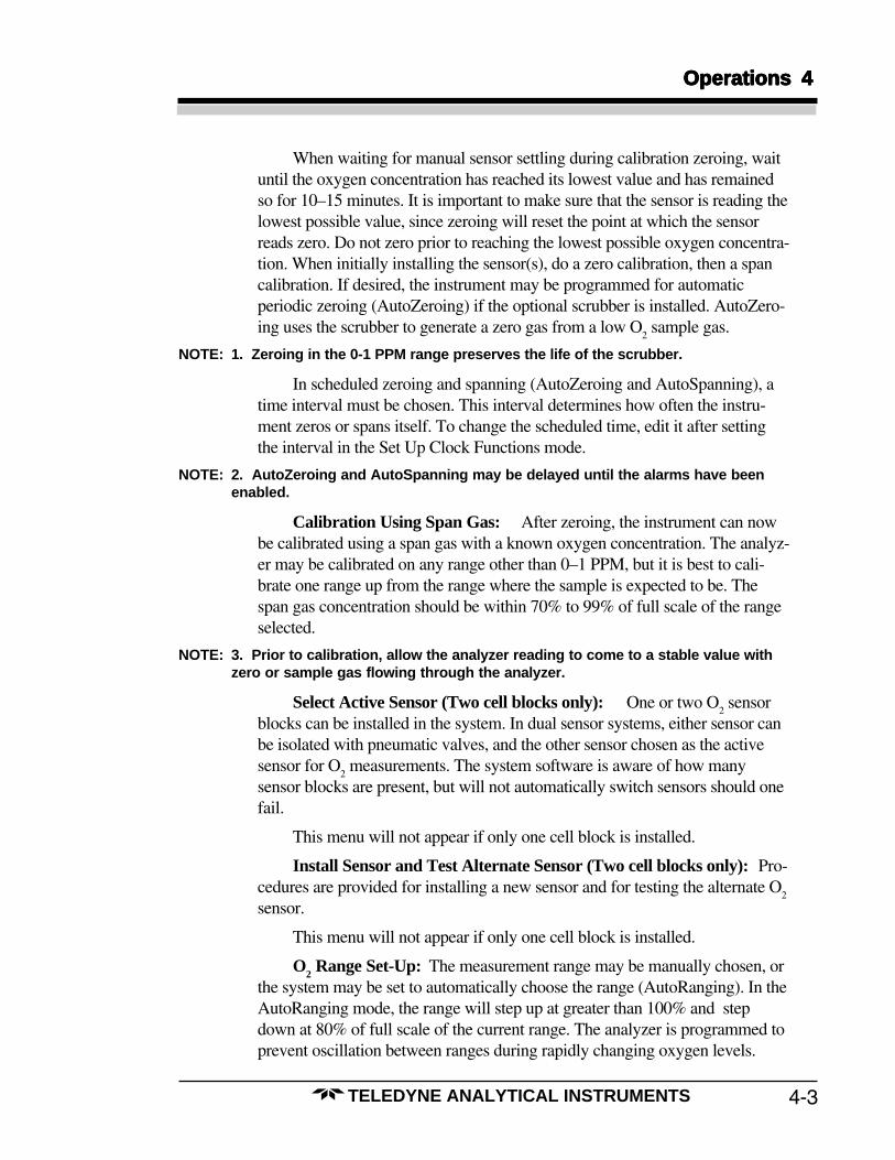
7. After pressing ACK in step 6, the new sensor is flushedfor 10 minutes while the measured O
2 level is displayed.
The 10-minute flush may be restarted by pressing RE-SET, or aborted by pressing SKIP.
8. When sensor installation or alternate sensor test arecomplete, the system will return to the main Analyzemode menu.
4-14
4 Operations4 Operations4 Operations4 Operations4 Operations
TELEDYNE ANALYTICAL INSTRUMENTS
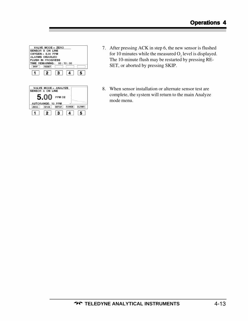
1. Enter Range Set-Up mode from the Analyze mode bypressing RANGE.
2. Press AUTO for AutoRanging, or FIXED to manuallyfix the O
2 measurement range. In AutoRange mode, the
range will be automatically determined so that the O2
measurements are within a range which maximizes theaccuracy of the reading.
3. If AUTO is chosen in step 2, the main Analyze modemenu will appear, and will indicate the automatically de-termined range (see screen for step 1).If FIXED is chosen in step 2, use the UP and DOWNkeys to choose the desired manual range, and pressACCPT.
4. If FIXED was chosen in step 2 and the range was speci-fied in step 3, the main Analyze mode screen will ap-pear, and will indicate the new manually set range.
OOOOO22222 Range Set-Up Range Set-Up Range Set-Up Range Set-Up Range Set-Up

4-15
Operations 4Operations 4Operations 4Operations 4Operations 4
TELEDYNE ANALYTICAL INSTRUMENTS
1. Enter set-up from the Analyze mode by pressingSETUP.
2. Press SET to set the alarms.
3. Enter the authorization code by using the SELEC, UPand DOWN keys, and press ACCPT.If this is a COLD START, the code you enter will bethe code set for every subsequent start-up until the nextCOLD START.If this is a WARM START, enter the code used duringthe last COLD START.
4. Press ALRMS.
5. Press• AL1 for alarm 1• AL2 for alarm 2• MORE for alarms 3–5• ESC twice to return to the main menu
Note that alarm 5 may be programmed as a systemalarm.
6. If AL1 or AL2 was chosen in step 5, use the SELEC,UP and DOWN keys to configure alarm 1 or 2, andpress ACCPT, which will take you back to step 5.
• LEVEL is the O2 concentration for the alarm
threshold.• HIGH/LOW determines whether the alarm con-
dition is above or below the alarm threshold.
Set-Up AlarmsSet-Up AlarmsSet-Up AlarmsSet-Up AlarmsSet-Up Alarms

4-16
4 Operations4 Operations4 Operations4 Operations4 Operations
TELEDYNE ANALYTICAL INSTRUMENTS
• LATCHING actuates the alarm above a certainsetpoint even if the level falls back below thesetpoint.
• RELAY indicates the relay (on the rear panel)actuated by the alarm, which is changeable.
• FAILSAFE=YES enables the relay which actu-ates the alarm during system failure.
• DEFEAT=NO actuates the alarms for normaluse.
7. If MORE was pressed in step 5, choose alarms 3, 4, or 5by pressing AL3, AL4, or AL5.Choose AL5 to set-up a system alarm.
8. If AL5 was pressed in step 7, choose alarm 5 to be anO
2 or system alarm by pressing O
2 or SYSTEM.
Configured as a system alarm, alarm 5 will ring when ascheduled calibrator zeroing or a scheduled span calibra-tion fails, when there is an internal system failure, orwhen the RAM back-up battery fails.
9. If SYSTM was pressed in step 8, configure the systemalarm using the SELEC, UP and DOWN keys.
• LATCHING=YES actuates alarm 5 above a cer-tain setpoint even if the level falls back below thesetpoint.
• FAILSAFE=YES enables the relay which actu-ates the alarm during system failure.
• DEFEAT=YES actuates the alarm for normaluse.
Press ACCPT to accept the new system alarm configu-ration. The next screen will ask you if there are morealarms to set. If not, pressing ESC three times will takeyou back to the Analyze mode main menu.
10. If O2 was pressed in step 8, the screen will resemble the
one in step 6. Use the SELEC, UP and DOWN keys toconfigure alarm 5. When finished, press ACCPT. Thenext screen will ask you if there are more alarms to set.If not, pressing ESC three times will take you back tothe Analyze mode main menu.

4-17
Operations 4Operations 4Operations 4Operations 4Operations 4
TELEDYNE ANALYTICAL INSTRUMENTS
1. Enter set-up from the Analyze mode by pressingSETUP.
2. Press SET to set up the logger.
3. Enter the authorization code by using the SELEC, UPand DOWN keys. Then press ACCPT.
4. Press LOG for the logger functions. Press ESC to returnto the Analyze mode main menu.
5. Press CLEAR if you want to clear the current loggerdata. Press SETUP to continue setting up the logger.
6. If you chose SETUP in step 5, use SELEC to chooselogger ON/OFF, the time period between samples, orthe mode of measurement. Then choose EDIT tochange the values. After you are finished, press ACCPT,which will take you to step 4.The choices for the logger chart sampling mode (MODE=) are on the next page.
Logger Set-UpLogger Set-UpLogger Set-UpLogger Set-UpLogger Set-Up

4-18
4 Operations4 Operations4 Operations4 Operations4 Operations
TELEDYNE ANALYTICAL INSTRUMENTS
Note:Note:Note:Note:Note: The above screens use T to indicate two values: seconds and minutes. The first value isThe above screens use T to indicate two values: seconds and minutes. The first value isThe above screens use T to indicate two values: seconds and minutes. The first value isThe above screens use T to indicate two values: seconds and minutes. The first value isThe above screens use T to indicate two values: seconds and minutes. The first value isthe time period between samples on the logger, and is programmable. The second timethe time period between samples on the logger, and is programmable. The second timethe time period between samples on the logger, and is programmable. The second timethe time period between samples on the logger, and is programmable. The second timethe time period between samples on the logger, and is programmable. The second timevalue is the width of the logger chart page, and is not programmable. There are 64value is the width of the logger chart page, and is not programmable. There are 64value is the width of the logger chart page, and is not programmable. There are 64value is the width of the logger chart page, and is not programmable. There are 64value is the width of the logger chart page, and is not programmable. There are 64samples per logger chart page, and over 20 pages of past data which may be viewed.samples per logger chart page, and over 20 pages of past data which may be viewed.samples per logger chart page, and over 20 pages of past data which may be viewed.samples per logger chart page, and over 20 pages of past data which may be viewed.samples per logger chart page, and over 20 pages of past data which may be viewed.
ModeModeModeModeMode determines how to calculate the sample values shown on the logger chart:AverageAverageAverageAverageAverage: The average of all measurements in the time period between samples.MedianMedianMedianMedianMedian: The average of the minimum and the maximum values measured in the time
period between samples.MaximumMaximumMaximumMaximumMaximum: The maximum of all values measured in the time period between samples.MinimumMinimumMinimumMinimumMinimum: The minimum of all values measured in the time period between samples.SampleSampleSampleSampleSample: The last sample measured in the time period between samples.
Press EDIT in step 6 and then use the UP and DOWN keys to select the above choices for thelogger chart mode.
4-19
Operations 4Operations 4Operations 4Operations 4Operations 4
TELEDYNE ANALYTICAL INSTRUMENTS
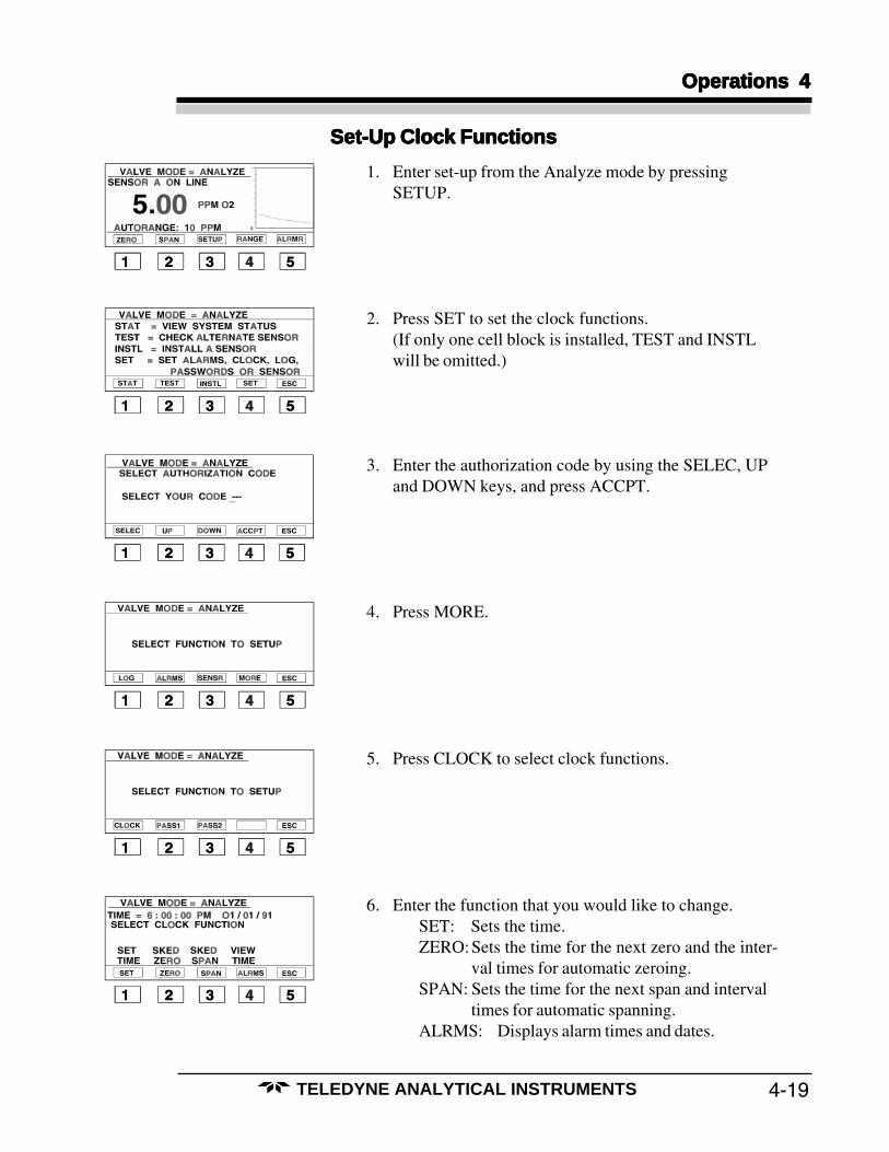
1. Enter set-up from the Analyze mode by pressingSETUP.
2. Press SET to set the clock functions.(If only one cell block is installed, TEST and INSTLwill be omitted.)
3. Enter the authorization code by using the SELEC, UPand DOWN keys, and press ACCPT.
4. Press MORE.
5. Press CLOCK to select clock functions.
6. Enter the function that you would like to change.SET: Sets the time.ZERO:Sets the time for the next zero and the inter-
val times for automatic zeroing.SPAN: Sets the time for the next span and interval
times for automatic spanning.ALRMS: Displays alarm times and dates.
Set-Up Clock FunctionsSet-Up Clock FunctionsSet-Up Clock FunctionsSet-Up Clock FunctionsSet-Up Clock Functions
4-20
4 Operations4 Operations4 Operations4 Operations4 Operations
TELEDYNE ANALYTICAL INSTRUMENTS
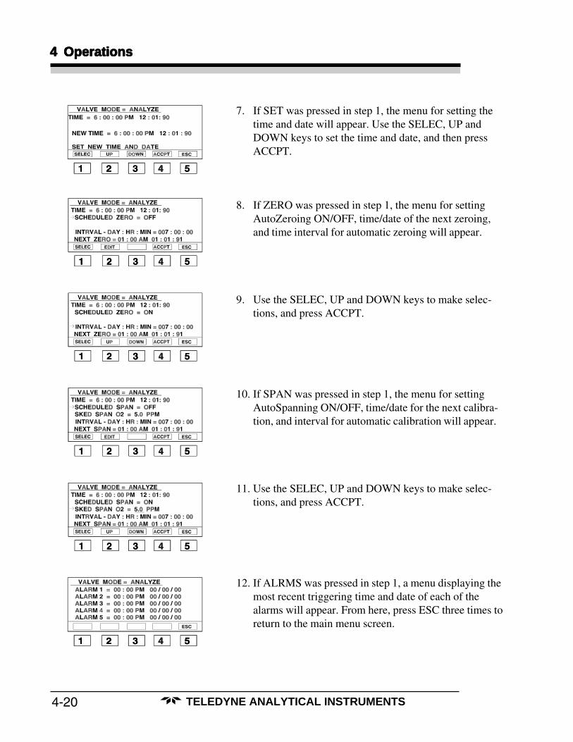
7. If SET was pressed in step 1, the menu for setting thetime and date will appear. Use the SELEC, UP andDOWN keys to set the time and date, and then pressACCPT.
8. If ZERO was pressed in step 1, the menu for settingAutoZeroing ON/OFF, time/date of the next zeroing,and time interval for automatic zeroing will appear.
9. Use the SELEC, UP and DOWN keys to make selec-tions, and press ACCPT.
10. If SPAN was pressed in step 1, the menu for settingAutoSpanning ON/OFF, time/date for the next calibra-tion, and interval for automatic calibration will appear.
11. Use the SELEC, UP and DOWN keys to make selec-tions, and press ACCPT.
12. If ALRMS was pressed in step 1, a menu displaying themost recent triggering time and date of each of thealarms will appear. From here, press ESC three times toreturn to the main menu screen.
4-21
Operations 4Operations 4Operations 4Operations 4Operations 4
TELEDYNE ANALYTICAL INSTRUMENTS
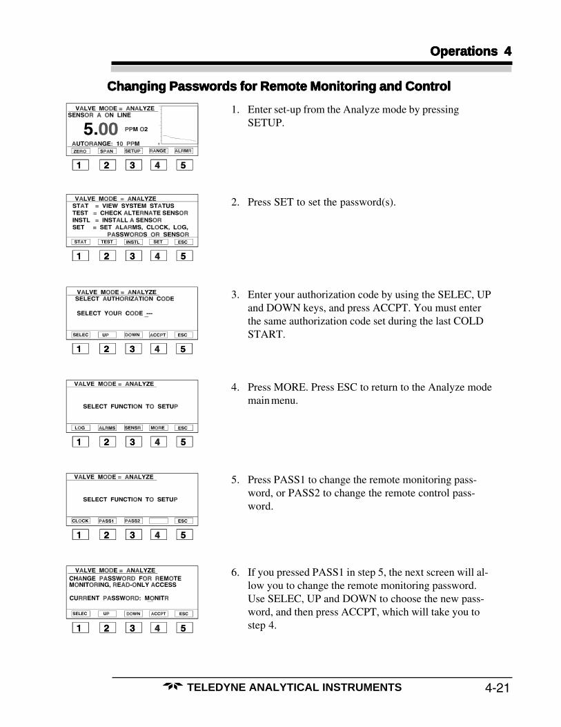
1. Enter set-up from the Analyze mode by pressingSETUP.
2. Press SET to set the password(s).
3. Enter your authorization code by using the SELEC, UPand DOWN keys, and press ACCPT. You must enterthe same authorization code set during the last COLDSTART.
4. Press MORE. Press ESC to return to the Analyze modemain menu.
5. Press PASS1 to change the remote monitoring pass-word, or PASS2 to change the remote control pass-word.
6. If you pressed PASS1 in step 5, the next screen will al-low you to change the remote monitoring password.Use SELEC, UP and DOWN to choose the new pass-word, and then press ACCPT, which will take you tostep 4.
Changing Passwords for Remote Monitoring and ControlChanging Passwords for Remote Monitoring and ControlChanging Passwords for Remote Monitoring and ControlChanging Passwords for Remote Monitoring and ControlChanging Passwords for Remote Monitoring and Control

4-22
4 Operations4 Operations4 Operations4 Operations4 Operations
TELEDYNE ANALYTICAL INSTRUMENTS
7. If you pressed PASS2 in step 5, the next screen will al-low you to change the remote control password. UseSELEC, UP and DOWN to choose the new password,and press ACCPT, which will take you to step 4.

4-23
Operations 4Operations 4Operations 4Operations 4Operations 4
TELEDYNE ANALYTICAL INSTRUMENTS
1. Enter set-up from the Analyze mode by pressingSETUP.ESC in any status page will take you to the last set-upscreen and eventually the main analyze mode.PREV steps you back one status page.NEXT moves forward one status page.
2. Press STAT for system status.(If only one cell block is installed, TEST and INSTLwill be omitted.)
3. Status page one displays the active sensor (A or B), thesystem time/date, and the system hardware configura-tion. The number and date of the installed software ver-sion are also shown.Press PREV for the previous screen, or NEXT for thenext screen.
4. Status page two shows the O2 level set for spanning, the
cell strength factor, the type and time of the last span,the time interval for scheduled spanning (AutoSpan),and whether or not scheduled spanning is active. [Thecell strength factor is an indication of the amount of celllife left in the cell, with 1.00 being the most and 0.00 be-ing the least.]
5. Status page three shows the time of the last zero, thetime interval for scheduled zeroing (AutoZero), andwhether or not scheduled zeroing is active.
6. Status page four shows the settings for the five pro-grammable alarms.
System StatisticsSystem StatisticsSystem StatisticsSystem StatisticsSystem Statistics
4-24
4 Operations4 Operations4 Operations4 Operations4 Operations
TELEDYNE ANALYTICAL INSTRUMENTS
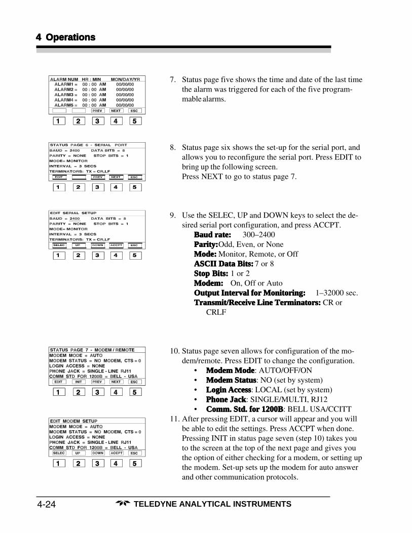
7. Status page five shows the time and date of the last timethe alarm was triggered for each of the five program-mable alarms.
8. Status page six shows the set-up for the serial port, andallows you to reconfigure the serial port. Press EDIT tobring up the following screen.Press NEXT to go to status page 7.
9. Use the SELEC, UP and DOWN keys to select the de-sired serial port configuration, and press ACCPT.
Baud rate:Baud rate:Baud rate:Baud rate:Baud rate: 300–2400Parity:Parity:Parity:Parity:Parity:Odd, Even, or NoneMode:Mode:Mode:Mode:Mode: Monitor, Remote, or OffASCII Data Bits:ASCII Data Bits:ASCII Data Bits:ASCII Data Bits:ASCII Data Bits: 7 or 8Stop Bits:Stop Bits:Stop Bits:Stop Bits:Stop Bits: 1 or 2Modem:Modem:Modem:Modem:Modem: On, Off or AutoOutput Interval for Monitoring:Output Interval for Monitoring:Output Interval for Monitoring:Output Interval for Monitoring:Output Interval for Monitoring: 1–32000 sec.Transmit/Receive Line Terminators:Transmit/Receive Line Terminators:Transmit/Receive Line Terminators:Transmit/Receive Line Terminators:Transmit/Receive Line Terminators: CR or
CRLF
10. Status page seven allows for configuration of the mo-dem/remote. Press EDIT to change the configuration.
• Modem ModeModem ModeModem ModeModem ModeModem Mode: AUTO/OFF/ON• Modem StatusModem StatusModem StatusModem StatusModem Status: NO (set by system)• Login AccessLogin AccessLogin AccessLogin AccessLogin Access: LOCAL (set by system)• Phone JackPhone JackPhone JackPhone JackPhone Jack: SINGLE/MULTI, RJ12• Comm. Std. for 1200BComm. Std. for 1200BComm. Std. for 1200BComm. Std. for 1200BComm. Std. for 1200B: BELL USA/CCITT
11. After pressing EDIT, a cursor will appear and you willbe able to edit the settings. Press ACCPT when done.Pressing INIT in status page seven (step 10) takes youto the screen at the top of the next page and gives youthe option of either checking for a modem, or setting upthe modem. Set-up sets up the modem for auto answerand other communication protocols.

4-25
Operations 4Operations 4Operations 4Operations 4Operations 4
TELEDYNE ANALYTICAL INSTRUMENTS
12. After checking for the modem, pressing ESC returnsyou to status page seven in step 10.If INIT was pressed in status page 7 and then SETUPpressed in step 11, pressing ACK will return you to thisscreen. Press ESC to return to status page seven in step10.
13. If you have purchased the parallel printer option, statuspage eight allows for configuration of the port. PressEDIT to change the configuration.
• ModeModeModeModeMode: ON/OFF• IntervalIntervalIntervalIntervalInterval: 3–32000 seconds
NOTE:NOTE:NOTE:NOTE:NOTE: The printer report will always be in the same for-The printer report will always be in the same for-The printer report will always be in the same for-The printer report will always be in the same for-The printer report will always be in the same for-mat—Omat—Omat—Omat—Omat—O22222 Level, Range, Active Sensor, Time & Date. Level, Range, Active Sensor, Time & Date. Level, Range, Active Sensor, Time & Date. Level, Range, Active Sensor, Time & Date. Level, Range, Active Sensor, Time & Date.
14. After pressing EDIT, a cursor will appear and you willbe able to edit the settings.
15. Status page nine shows whether or not the last and nextstart-ups were WARM or COLD. The next start-up maybe changed by pressing the COLD or WARM keys.
16. Status page ten displays logger data. Press VIEW to seethe logger data history. Press NEXT to return to statuspage one. Press ESC twice to return to the Analyzemode main menu.
17. If VIEW was pressed in step 13, logger data may beviewed by using the +, –, REV and FWD keys. The O
2
level, range, and time are shown for each data point.NEXT takes you to status page two.REV and FWD change the date by one page (or 64points), while – and + go through the data one point at atime within a single page. Press ESC to return to statuspage ten.

4-26
4 Operations4 Operations4 Operations4 Operations4 Operations
TELEDYNE ANALYTICAL INSTRUMENTS

5-1
Maintenance & Maintenance & Maintenance & Maintenance & Maintenance & TTTTTrrrrroubouboubouboubleshooting 5leshooting 5leshooting 5leshooting 5leshooting 5
TELEDYNE ANALYTICAL INSTRUMENTS
Maintenance & Troubleshooting
5.1 Routine Maintenance
1. Calibrate the analyzer at least once each week during the first four weeksand then once every two weeks during the next eight weeks. Afterwards,the analyzer should be calibrated once a month.
2. Check the pressure of the air supply to the analyzer. Air pressure should bemaintained between 70 and 80 psig.
Note: The instrument air pressure must be greater than 70 psig in order to openand close the pneumatic solenoid valves.
3. Check the sample pressure. Pressure should be maintained between 5 and10 psig. Sample and span gas pressures should be within ±2 psig of eachother.
5.1.1 Sensor Maintenance
Sensor maintenance in the 3160 is limited to replacing the sensor(s) when replace-ment is indicated. Consult the troubleshooting section for symptoms that indicate that thesensor needs replacing.
A guide to the relative life left in the cell can be found on status page 2. See “CellStrength Factor” at the beginning of Chapter 3.0.
In units with 2 cell blocks, if sensor A fails, sensor B will not automatically switchonline. This must be done manually through the Install Sensor and Test Alternate Sensormenu.
5.1.2 Scrubber Maintenance
The oxygen scrubber is a replaceable component. With normal use, the scrubberusually lasts for several years.
NOTE: Do not zero in ranges other than 0-1 ppm, as zeroing in higher ranges willexhaust the scrubber.
5-2
5 Maintenance & 5 Maintenance & 5 Maintenance & 5 Maintenance & 5 Maintenance & TTTTTrrrrroubouboubouboubleshootingleshootingleshootingleshootingleshooting
TELEDYNE ANALYTICAL INSTRUMENTS
Analyzers equipped with a scrubber should only be used with inert gases and saturat-ed hydrocarbons.
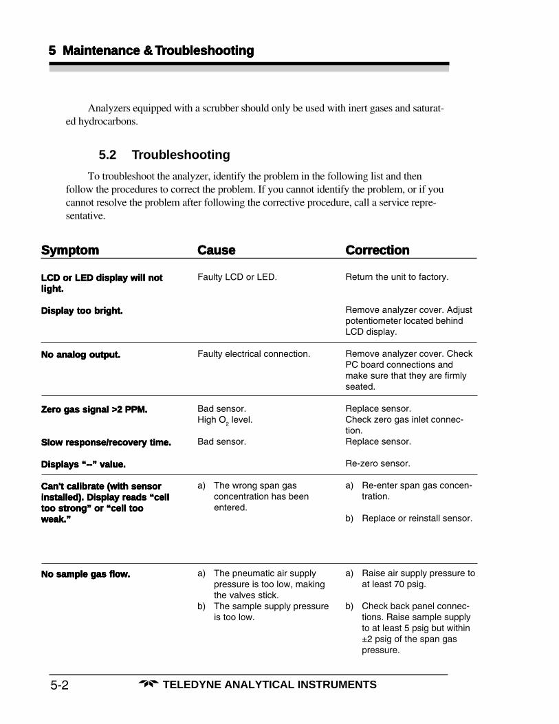
5.2 Troubleshooting
To troubleshoot the analyzer, identify the problem in the following list and thenfollow the procedures to correct the problem. If you cannot identify the problem, or if youcannot resolve the problem after following the corrective procedure, call a service repre-sentative.
LCD or LED display will notLCD or LED display will notLCD or LED display will notLCD or LED display will notLCD or LED display will notlight.light.light.light.light.
Display too bright.Display too bright.Display too bright.Display too bright.Display too bright.
No analog output.No analog output.No analog output.No analog output.No analog output.
Zero gas signal >2 PPM.Zero gas signal >2 PPM.Zero gas signal >2 PPM.Zero gas signal >2 PPM.Zero gas signal >2 PPM.
Slow response/recovery time.Slow response/recovery time.Slow response/recovery time.Slow response/recovery time.Slow response/recovery time.
Displays “--” value.Displays “--” value.Displays “--” value.Displays “--” value.Displays “--” value.
Can't calibrate (with sensorCan't calibrate (with sensorCan't calibrate (with sensorCan't calibrate (with sensorCan't calibrate (with sensorinstalled). Display reads “cellinstalled). Display reads “cellinstalled). Display reads “cellinstalled). Display reads “cellinstalled). Display reads “celltoo strong” or “cell tootoo strong” or “cell tootoo strong” or “cell tootoo strong” or “cell tootoo strong” or “cell tooweak.”weak.”weak.”weak.”weak.”
No sample gas flow.No sample gas flow.No sample gas flow.No sample gas flow.No sample gas flow.
Return the unit to factory.
Remove analyzer cover. Adjustpotentiometer located behindLCD display.
Remove analyzer cover. CheckPC board connections andmake sure that they are firmlyseated.
Replace sensor.Check zero gas inlet connec-tion.Replace sensor.
Re-zero sensor.
a) Re-enter span gas concen-tration.
b) Replace or reinstall sensor.
a) Raise air supply pressure toat least 70 psig.
b) Check back panel connec-tions. Raise sample supplyto at least 5 psig but within±2 psig of the span gaspressure.
Faulty LCD or LED.
Faulty electrical connection.
Bad sensor.High O
2 level.
Bad sensor.
a) The wrong span gasconcentration has beenentered.
a) The pneumatic air supplypressure is too low, makingthe valves stick.
b) The sample supply pressureis too low.
SymptomSymptomSymptomSymptomSymptom CauseCauseCauseCauseCause CorrectionCorrectionCorrectionCorrectionCorrection
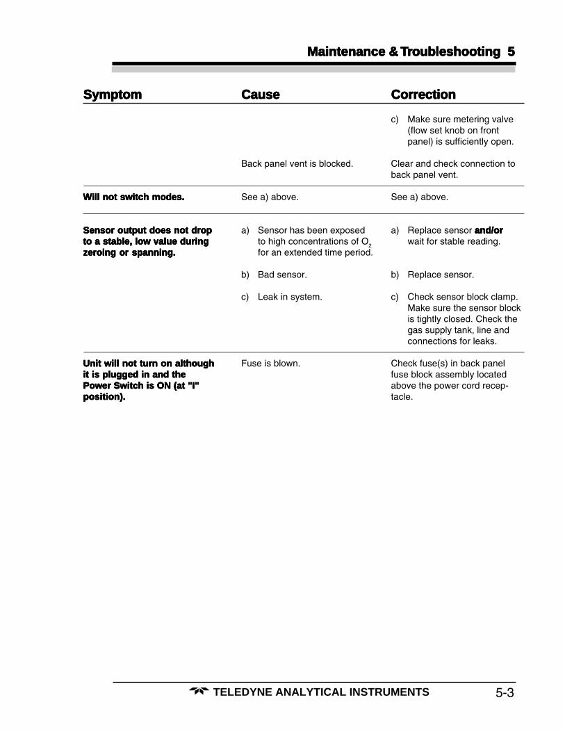
5-3
Maintenance & Maintenance & Maintenance & Maintenance & Maintenance & TTTTTrrrrroubouboubouboubleshooting 5leshooting 5leshooting 5leshooting 5leshooting 5
TELEDYNE ANALYTICAL INSTRUMENTS
SymptomSymptomSymptomSymptomSymptom CauseCauseCauseCauseCause CorrectionCorrectionCorrectionCorrectionCorrection
Will not switch modes.Will not switch modes.Will not switch modes.Will not switch modes.Will not switch modes.
Sensor output does not dropSensor output does not dropSensor output does not dropSensor output does not dropSensor output does not dropto a stable, low value duringto a stable, low value duringto a stable, low value duringto a stable, low value duringto a stable, low value duringzeroing or spanning.zeroing or spanning.zeroing or spanning.zeroing or spanning.zeroing or spanning.
Unit will not turn on althoughUnit will not turn on althoughUnit will not turn on althoughUnit will not turn on althoughUnit will not turn on althoughit is plugged in and theit is plugged in and theit is plugged in and theit is plugged in and theit is plugged in and thePower Switch is ON (at "I"Power Switch is ON (at "I"Power Switch is ON (at "I"Power Switch is ON (at "I"Power Switch is ON (at "I"position).position).position).position).position).
Back panel vent is blocked.
See a) above.
a) Sensor has been exposedto high concentrations of O
2
for an extended time period.
b) Bad sensor.
c) Leak in system.
Fuse is blown.
c) Make sure metering valve(flow set knob on frontpanel) is sufficiently open.
Clear and check connection toback panel vent.
See a) above.
a) Replace sensor and/orand/orand/orand/orand/orwait for stable reading.
b) Replace sensor.
c) Check sensor block clamp.Make sure the sensor blockis tightly closed. Check thegas supply tank, line andconnections for leaks.
Check fuse(s) in back panelfuse block assembly locatedabove the power cord recep-tacle.

5-4
5 Maintenance & 5 Maintenance & 5 Maintenance & 5 Maintenance & 5 Maintenance & TTTTTrrrrroubouboubouboubleshootingleshootingleshootingleshootingleshooting
TELEDYNE ANALYTICAL INSTRUMENTS

A-1
AppendixAppendixAppendixAppendixAppendix
TELEDYNE ANALYTICAL INSTRUMENTS
Appendix
A.1 Specifications(Subject to change without notice.)
Ranges: (Six ranges with AutoRanging on all ranges)1: 0–1 part per million (ppm) O
2
2: 0–10 ppm O2
3: 0–100 ppm O2
4: 0–1000 ppm O2
5: 0–1 % O2
6: 0–25 % O2
Accuracy: ±2% of full scale when calibrated and operated at the same constanttemperature and pressure.*±5% of full scale over the operating temperature range once tempera-ture equilibrium is reached.*
* Additional 0.04 ppm on 0-1 ppm range, generated by internal scrub-ber (which is necessary to maintain these specifications).
Response Time: 90 % of final reading in less than 61 seconds at 25 °C
Operating Temperature:0-50°C (32 -122 °F)
Analog Signal Outputs: For percent of full scale indication:one 0–1 V dc non-isolated signalone 4–20 mA dc isolated signal
For range identification:one 0–1 V dc non-isolated signalone 4–20 mA dc isolated signal
Digital Data Lines: One RS-232C serial interface for 2-way communicationswith separate host computer—for remote monitoring andcontrol of all functions.
Alarms: Five user-programmable absolute-reading alarm setpoints,with Form C, SPDT relays (3A resistive).

A-2
AppendixAppendixAppendixAppendixAppendix
TELEDYNE ANALYTICAL INSTRUMENTS
Mounting and Enclosure: 19" relay rack, 20.3 cm (12.25 inches) high,for general purpose (nonhazardous) areas.(Class I, Division II, hazardous area modelsavailable on special order.)
Sensor: Class B-2, B2C, A2, or A2C, Micro-FuelCells.
Altitude: 1,609 mRelative Humidy: Up to 99%
Power Requirements: 100, 120, 220, or 240~ 50-60 Hz 1.5 A MAXUse 250 V 3.0 A T Fuse for 110, 120 V~Use 250 V 1.6 A T Fuse for 220, 240 V~
TELEDYNE Analytical Instruments
16830 Chestnut StreetCity of Industry, CA 91749-1580
Phone (626) 934-1500,
Fax (626) 961-2538
TWX (910) 584-1887 TDYANYL COID
Web: www.teledyne-ai.com

A-3
AppendixAppendixAppendixAppendixAppendix
TELEDYNE ANALYTICAL INSTRUMENTS
A.2 Recommended Spare Parts List
Description P/N
Micro-Fuel Cell sensor C6689B2C6689B2C
C6689A2C6689A2C
O-ring O165
Suction purifier P670
Solenoid valve V462
Pneumatic valve upper body B435
Hose fitting tee T978
Fuse, 3A T Type F68
Fuse, 1.6A T Type (European) F768
Scrubber C58750
A.3 Drawing List
D-56534 Outline Drawing
C-64819 Interconnection Drawing
NOTE: The MSDS on this material is available upon requestthrough the Teledyne Environmental, Health andSafety Coordinator. Contact at (626) 934-1592
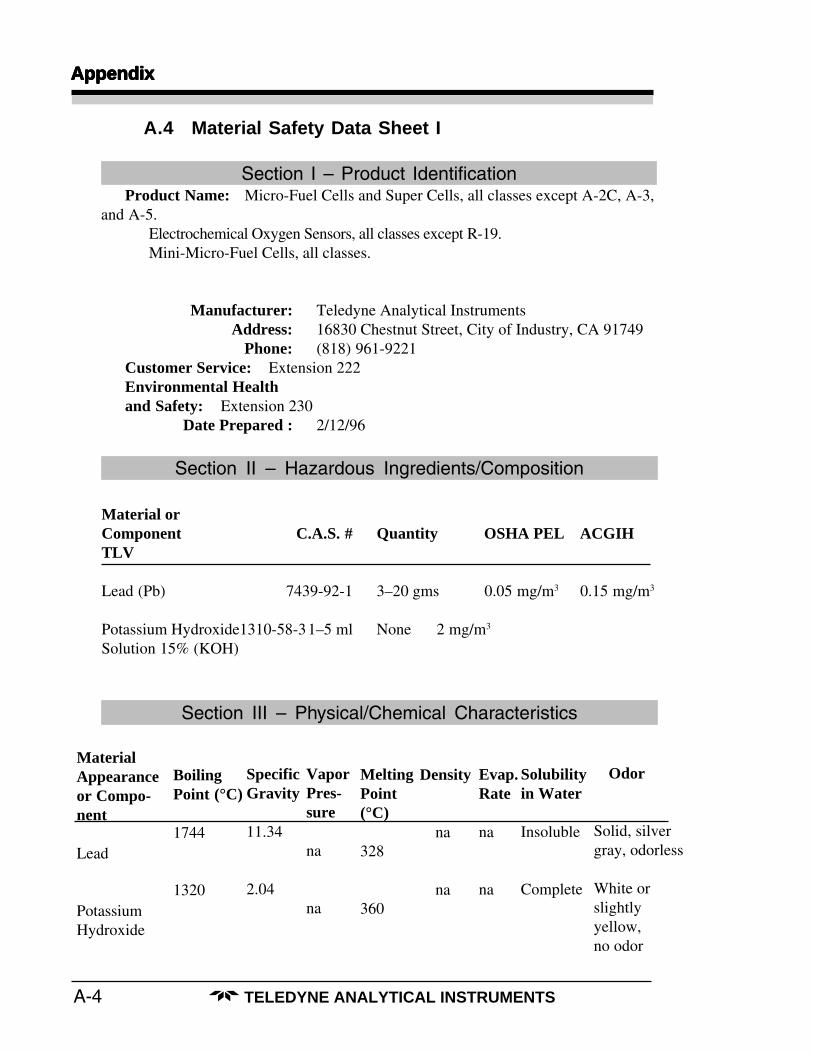
A-4
AppendixAppendixAppendixAppendixAppendix
TELEDYNE ANALYTICAL INSTRUMENTS
A.4 Material Safety Data Sheet I
Product Name: Micro-Fuel Cells and Super Cells, all classes except A-2C, A-3,and A-5.
Electrochemical Oxygen Sensors, all classes except R-19.Mini-Micro-Fuel Cells, all classes.
Manufacturer: Teledyne Analytical InstrumentsAddress: 16830 Chestnut Street, City of Industry, CA 91749
Phone: (818) 961-9221Customer Service: Extension 222Environmental Healthand Safety: Extension 230
Date Prepared : 2/12/96
Section I – Product Identification
Section III – Physical/Chemical Characteristics
Section II – Hazardous Ingredients/Composition
Material orComponent C.A.S. # Quantity OSHA PEL ACGIHTLV
Lead (Pb) 7439-92-1 3–20 gms 0.05 mg/m3 0.15 mg/m3
Potassium Hydroxide1310-58-31–5 ml None 2 mg/m3
Solution 15% (KOH)
SpecificGravity
11.34
2.04
Solubilityin Water
Insoluble
Complete
Odor
Solid, silvergray, odorless
White orslightlyyellow,no odor
Evap.Rate
na
na
MeltingPoint(°C)
328
360
BoilingPoint (°C)
1744
1320
MaterialAppearanceor Compo-nent
Lead
PotassiumHydroxide
VaporPres-sure
na
na
Density
na
na

A-5
AppendixAppendixAppendixAppendixAppendix
TELEDYNE ANALYTICAL INSTRUMENTS
Flash Point: na Flammable Limits: na LEL: na UEL: na
Extinguishing Media: Use extinguishing media appropriate to surrounding fireconditions. No specific agents recommended.
Wear NIOSH/OSHA approved self-contained breathingapparatus and protective clothing to prevent contact withskin and eyes.
Emits toxic fumes under fire conditions.
Special Fire FightingEquipment:
Unusual Fire and ExplosionHazards:
Section IV – Fire and Explosion Hazard Data
Section V – Reactivity Data
Hazardous Decomposition ofByproducts:
Routes of Entry: Inhalation: Highly unlikely
Ingestion: May be fatal if swallowed.
Skin: The electrolyte (potassium hydroxide) is corrosive; skincontact may cause irritation or chemical burns.
Eyes: The electrolyte (potassium hydroxide) is corrosive; eyecontact may cause irritation or severe chemical burns.
Acute Effects: The electrolyte is harmful if swallowed, inhaled oradsorbed through the skin. It is extremely destructive totissue of the mucous membranes, stomach, mouth, upperrespiratory tract, eyes and skin.
Chronic Effects: Prolonged exposure with the electrolyte has a destructiveeffect on tissue.
Chronic exposure to lead may cause disease of the bloodand blood forming organs, kidneys and liver, damage tothe reproductive systems and decrease in fertility in menand women, and damage to the fetus of a pregnantwoman. Chronic exposure from the lead contained in thisproduct is extremely unlikely.
Section VI – Health Hazard Data
Stability: Stable
Incompatibilities: Aluminum, organic materials, acid chlorides, acidanhydrides, magnesium, copper. Avoid contact with acidsand hydrogen peroxide > 52%.
Toxic fumes
Hazardous Polymerization: Will not occur.

A-6
AppendixAppendixAppendixAppendixAppendix
TELEDYNE ANALYTICAL INSTRUMENTS
Contact of electrolyte with skin or eyes will cause aburning sensation and/or feel soapy or slippery to touch.
Other symptoms of exposure to lead include loss of sleep,loss of appetite, metallic taste and fatigue.
Carcinogenicity: Lead is classified by the IARC as a class 2B carcinogen(possibly carcinogenic to humans).
OSHA: Where airborne lead exposures exceed the OSHA actionlevel, refer to OSHA Lead Standard 1910.1025.
NTP: na
Lead exposure may aggravate disease of the blood andblood forming organs, hypertension, kidneys, nervousand possibly reproductive systems. Those with preexist-ing skin disorders or eye problems may be more suscepti-ble to the effects of the electrolyte.
In case of contact with the skin or eyes, immediatelyflush with plenty of water for at least 15 minutes andremove all contaminated clothing. Get medical attentionimmediately.
If ingested, give large amounts of water and DO NOTINDUCE VOMITING. Obtain medical attention immedi-ately.
If inhaled, remove to fresh air and obtain medicalattention immediately.
Medical Conditions GenerallyAggravated by Exposure:
Signs and Symptoms ofExposure:
Emergency First Aid Procedures:
NOTE: The oxygen sensors are sealed, and under normal circum-stances, the contents of the sensors do not present a healthhazard. The following information is given as a guide in theevent that a cell leaks.
Section VII – Precautions for Safe Handling and Use
Before opening the bag containing the sensor cell, checkthe sensor cell for leakage. If the sensor cell leaks, do notopen the bag. If there is liquid around the cell while inthe instrument, wear eye and hand protection.
Cleanup Procedures: Wipe down the area several times with a wet paper towel.Use a fresh towel each time. Contaminated paper towelsare considered hazardous waste.
Protective measuresduring cell replacement:
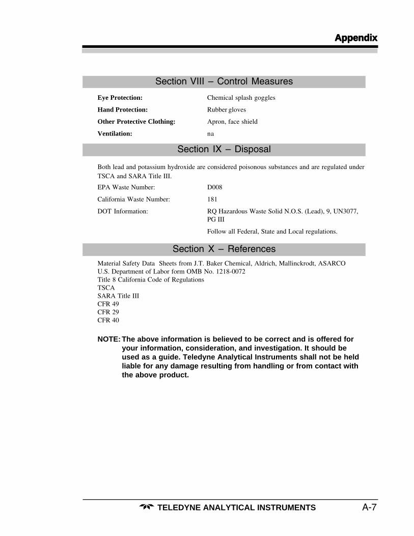
A-7
AppendixAppendixAppendixAppendixAppendix
TELEDYNE ANALYTICAL INSTRUMENTS
Section VIII – Control Measures
Eye Protection: Chemical splash goggles
Hand Protection: Rubber gloves
Other Protective Clothing: Apron, face shield
Ventilation: na
Section IX – Disposal
Both lead and potassium hydroxide are considered poisonous substances and are regulated underTSCA and SARA Title III.
EPA Waste Number: D008
California Waste Number: 181
DOT Information: RQ Hazardous Waste Solid N.O.S. (Lead), 9, UN3077,PG III
Follow all Federal, State and Local regulations.
Section X – ReferencesMaterial Safety Data Sheets from J.T. Baker Chemical, Aldrich, Mallinckrodt, ASARCOU.S. Department of Labor form OMB No. 1218-0072Title 8 California Code of RegulationsTSCASARA Title IIICFR 49CFR 29CFR 40
NOTE: The above information is believed to be correct and is offered foryour information, consideration, and investigation. It should beused as a guide. Teledyne Analytical Instruments shall not be heldliable for any damage resulting from handling or from contact withthe above product.

A-8
AppendixAppendixAppendixAppendixAppendix
TELEDYNE ANALYTICAL INSTRUMENTS
A.5 Material Safety Data Sheet II
Section I – Product Identification
Product Name: Micro-Fuel CellsMini-Micro-Fuel Cells, all classesSuper Cells, all classes except T–5FOxygen Sensors, all classes.
Manufacturer: Teledyne Analytical InstrumentsAddress: 16830 Chestnut Street, City of Industry, CA 91749
Phone: (818) 961-9221Date Prepared or Last Revised: 08/08/91
Emergency Phone Number: (818) 961-9221
Section II – Physical and Chemical Data
Chemical and Common Names: Potassium Hydoxide (KOH), 15% (w/v)Lead (Pb), pure
CAS Number: KOH 1310–58–3Pb 7439–92–1
KOH (15% w/v) Pb (pure)Melting Point/Range: –10 to 0 °C 328 °CBoiling Point/Range: 100 to 115 °C 1744 °C
Specific Gravity: 1.09 @ 20 °C 11.34pH: >14 N/A
Solubility in Water: Completely soluble InsolublePercent Volatiles by Volume: None N/A
Appearance and Odor: Colorless, odorless solution Grey metal, odor-less

A-9
AppendixAppendixAppendixAppendixAppendix
TELEDYNE ANALYTICAL INSTRUMENTS
Section III – Physical Hazards
Potential for fire and explosion: The electrolyte in the Micro–Fuel Cells is not flam-mable. There are no fire or explosion hazards associated with Micro–Fuel Cells.
Potential for reactivity: The sensors are stable under normal conditions of use. Avoidcontact between the sensor electrolyte and strong acids.
Section IV – Health Hazard Data
Primary route of entry: Ingestion, eye/skin contactExposure limits:OSHA PEL: .05 mg/cu.m. (Pb)
ACGIH TLV: 2 mg/cu.m. (KOH)
Effects of overexposureIngestion: The electrolyte could be harmful or fatal if swal-
lowed.Oral LD50 (RAT) = 3650 mg/kg
Eye: The electrolyte is corrosive; eye contact could resultin permanent loss of vision.
Dermal: The electrolyte is corrosive; skin contact could resultin a chemical burn.
Inhalation: Liquid inhalation is unlikely.
Signs/symptoms of exposure: Contact with skin or eyes will cause a burning sensa-tion and/or feel soapy or slippery to touch.
Medical conditionsaggravated by exposure: None
Carcinogenity: NTP Annual Report on Carcinogens: Not listedLARC Monographs: Not listedOSHA: Not listed
Other health hazards: Lead is listed as a chemical known to the State ofCalifornia to cause birth defects or other reproductiveharm.

A-10
AppendixAppendixAppendixAppendixAppendix
TELEDYNE ANALYTICAL INSTRUMENTS
Section V – Emergency and First Aid Procedures
Eye Contact: Flush eyes with water for at least 15 minutes and get immediatemedical attention.
Skin Contact: Wash affected area with plenty of water and remove contaminatedclothing. If burning persists, seek medical attention.
Ingestion: Give plenty of cold water. Do not induce vomiting. Seek medical at-tention. Do not administer liquids to an unconscious person.
Inhalation: Liquid inhalation is unlikely.
Section VI – Handling Information
NOTE:NOTE:NOTE:NOTE:NOTE: The oxygen sensors are sealed, and under normal circumstances, the contentsThe oxygen sensors are sealed, and under normal circumstances, the contentsThe oxygen sensors are sealed, and under normal circumstances, the contentsThe oxygen sensors are sealed, and under normal circumstances, the contentsThe oxygen sensors are sealed, and under normal circumstances, the contentsof the sensors do not present a health hazard. The following information is givenof the sensors do not present a health hazard. The following information is givenof the sensors do not present a health hazard. The following information is givenof the sensors do not present a health hazard. The following information is givenof the sensors do not present a health hazard. The following information is givenas a guide in the event that a cell leaks.as a guide in the event that a cell leaks.as a guide in the event that a cell leaks.as a guide in the event that a cell leaks.as a guide in the event that a cell leaks.
Protective clothing: Rubber gloves, chemical splash goggles.
Clean-up procedures: Wipe down the area several times with a wet paper towel.Use a fresh towel each time.
Protective measuresduring cell replacement: Before opening the bag containing the sensor cell, check the
sensor cell for leakage. If the sensor cell leaks, do not openthe bag. If there is liquid around the cell while in the instru-ment, put on gloves and eye protection before removing thecell.
Disposal: Should be in accordance with all applicable state, local andfederal regulations.
NOTE:NOTE:NOTE:NOTE:NOTE: The above information is derived from the MSDS provided by the manufacturer.The above information is derived from the MSDS provided by the manufacturer.The above information is derived from the MSDS provided by the manufacturer.The above information is derived from the MSDS provided by the manufacturer.The above information is derived from the MSDS provided by the manufacturer.The information is believed to be correct but does not purport to be all inclusiveThe information is believed to be correct but does not purport to be all inclusiveThe information is believed to be correct but does not purport to be all inclusiveThe information is believed to be correct but does not purport to be all inclusiveThe information is believed to be correct but does not purport to be all inclusiveand shall be used only as a guide. Teledyne Analytical Instruments shall not beand shall be used only as a guide. Teledyne Analytical Instruments shall not beand shall be used only as a guide. Teledyne Analytical Instruments shall not beand shall be used only as a guide. Teledyne Analytical Instruments shall not beand shall be used only as a guide. Teledyne Analytical Instruments shall not beheld liable for any damage resulting from handling or from contact with theheld liable for any damage resulting from handling or from contact with theheld liable for any damage resulting from handling or from contact with theheld liable for any damage resulting from handling or from contact with theheld liable for any damage resulting from handling or from contact with theabove product.above product.above product.above product.above product.