Embed Size (px)
Citation preview

ETSI TR 102 375 V1.2.1 (2007-08)
Technical Report
Satellite Earth Stations and Systems (SES);Guidelines for determining the parts of
satellite earth station antenna radiation patternsconcerned by the geostationary satellite orbit protection
�
ETSI
ETSI TR 102 375 V1.2.1 (2007-08) 2
Reference RTR/SES-00288
Keywords antenna, earth station, GSO, satellite
ETSI
650 Route des Lucioles F-06921 Sophia Antipolis Cedex - FRANCE
Tel.: +33 4 92 94 42 00 Fax: +33 4 93 65 47 16
Siret N° 348 623 562 00017 - NAF 742 C
Association à but non lucratif enregistrée à la Sous-Préfecture de Grasse (06) N° 7803/88
Important notice
Individual copies of the present document can be downloaded from: http://www.etsi.org
The present document may be made available in more than one electronic version or in print. In any case of existing or perceived difference in contents between such versions, the reference version is the Portable Document Format (PDF).
In case of dispute, the reference shall be the printing on ETSI printers of the PDF version kept on a specific network drive within ETSI Secretariat.
Users of the present document should be aware that the document may be subject to revision or change of status. Information on the current status of this and other ETSI documents is available at
http://portal.etsi.org/tb/status/status.asp
If you find errors in the present document, please send your comment to one of the following services: http://portal.etsi.org/chaircor/ETSI_support.asp
Copyright Notification
No part may be reproduced except as authorized by written permission. The copyright and the foregoing restriction extend to reproduction in all media.
© European Telecommunications Standards Institute 2007.
All rights reserved.
DECTTM, PLUGTESTSTM and UMTSTM are Trade Marks of ETSI registered for the benefit of its Members. TIPHONTM and the TIPHON logo are Trade Marks currently being registered by ETSI for the benefit of its Members. 3GPPTM is a Trade Mark of ETSI registered for the benefit of its Members and of the 3GPP Organizational Partners.

ETSI
ETSI TR 102 375 V1.2.1 (2007-08) 3
Contents
Intellectual Property Rights ................................................................................................................................5
Foreword.............................................................................................................................................................5
Introduction ........................................................................................................................................................5
1 Scope ........................................................................................................................................................7
2 References ................................................................................................................................................7
3 Definitions, symbols and abbreviations ...................................................................................................8 3.1 Definitions..........................................................................................................................................................8 3.2 Symbols..............................................................................................................................................................8 3.3 Abbreviations .....................................................................................................................................................8 3.4 Mathematical formulas.......................................................................................................................................8
4 GSO arc protection requirement...............................................................................................................9
5 Aspects of the GSO arc ..........................................................................................................................10 5.1 Aspect of the GSO arc from space ...................................................................................................................10 5.2 Aspect of the GSO arc from an Earth Station (ES) ..........................................................................................11 5.3 Aspect of the GSO arc from an ES antenna .....................................................................................................12 5.3.1 Types of antenna mounts ............................................................................................................................16 5.3.2 Azimuth-elevation antenna mount without GSO tangent alignment ..........................................................17 5.3.3 Azimuth-elevation antenna mount with GSO tangent alignment ...............................................................24 5.3.3.1 General ..................................................................................................................................................24 5.3.3.2 Ideal case...............................................................................................................................................25 5.3.3.3 Practical case of an antenna with a fixed polarizer ...............................................................................28 5.3.4 Equatorial antenna mount ...........................................................................................................................35 5.4 Minimum longitude offset................................................................................................................................40
6 Mathematical analysis ............................................................................................................................42 6.1 Geographical coordinates .................................................................................................................................42 6.2 Earth station geographical coordinates.............................................................................................................43 6.3 Satellite geographical coordinates ....................................................................................................................43 6.4 Local coordinates .............................................................................................................................................44 6.5 Satellite local coordinates.................................................................................................................................46 6.6 Other relationships between Satellite and ES coordinates................................................................................47 6.7 Antenna Cartesian coordinates .........................................................................................................................49 6.8 Antenna polar coordinates................................................................................................................................52 6.9 Antenna Az-axis alignment ..............................................................................................................................54 6.10 Az-axis alignment of an antenna with a fixed polarizer ...................................................................................56 6.11 Antenna with equatorial mount ........................................................................................................................58
7 Axis alignment offsets and errors...........................................................................................................60 7.1 Axis alignment errors with an azimuth-elevation mount..................................................................................60 7.1.1 General........................................................................................................................................................60 7.1.2 Case of no alignment of the antenna azimuth axis with i = 0 .....................................................................61 7.1.3 Case of no alignment of the antenna azimuth axis with i ≠ 0 .....................................................................66 7.1.4 Case of alignment of the antenna azimuth axis...........................................................................................68 7.2 Axis alignment errors with an equatorial mount ..............................................................................................69
8 Contour computation method.................................................................................................................74 8.1 General .............................................................................................................................................................74 8.2 Case of 1 ES and 1 satellite ..............................................................................................................................74 8.3 Case of ESs and satellites .................................................................................................................................75
9 Excel tool................................................................................................................................................75 9.1 General .............................................................................................................................................................75 9.2 Cell colours ......................................................................................................................................................76 9.3 Constants ..........................................................................................................................................................76

ETSI
ETSI TR 102 375 V1.2.1 (2007-08) 4
9.4 Buttons .............................................................................................................................................................76 9.5 Input data..........................................................................................................................................................77 9.6 Functions and Subroutines ...............................................................................................................................78 9.6.1 Function Azimuth().....................................................................................................................................78 9.6.2 Function Elevation() ...................................................................................................................................79 9.6.3 Function Phi_Az() ......................................................................................................................................79 9.6.4 Function Phi_El()........................................................................................................................................80 9.6.5 Functions Phi_cos_Alpha() and Phi_sin_Alpha().......................................................................................80 9.6.6 Function Inclination_with_Az_El_mount() ................................................................................................81 9.6.7 Function Inclination_with_E_field_alignment().........................................................................................81 9.6.8 Function Inclination_with_equatorial_mount() ..........................................................................................81 9.6.9 Function Az_El_mount_alignment_error().................................................................................................82 9.6.10 Function Az_El_mount_with_E_field_alignment_error()..........................................................................82 9.6.11 Function Equatorial_mount_alignment_error() ..........................................................................................83 9.6.12 Function Max_satellite_longitude_offset().................................................................................................83 9.6.13 Subroutine GSO_external_contour() ..........................................................................................................83 9.6.14 Subroutine GSO_internal_contour() ...........................................................................................................85 9.7 Output data and graphs.....................................................................................................................................86 9.7.1 General........................................................................................................................................................86 9.7.2 GSO shadow for a given ES and a given pointed satellite..........................................................................86
History ..............................................................................................................................................................88

ETSI
ETSI TR 102 375 V1.2.1 (2007-08) 5
Intellectual Property Rights IPRs essential or potentially essential to the present document may have been declared to ETSI. The information pertaining to these essential IPRs, if any, is publicly available for ETSI members and non-members, and can be found in ETSI SR 000 314: "Intellectual Property Rights (IPRs); Essential, or potentially Essential, IPRs notified to ETSI in respect of ETSI standards", which is available from the ETSI Secretariat. Latest updates are available on the ETSI Web server (http://webapp.etsi.org/IPR/home.asp).
Pursuant to the ETSI IPR Policy, no investigation, including IPR searches, has been carried out by ETSI. No guarantee can be given as to the existence of other IPRs not referenced in ETSI SR 000 314 (or the updates on the ETSI Web server) which are, or may be, or may become, essential to the present document.
Foreword This Technical Report (TR) has been produced by ETSI Technical Committee Satellite Earth Stations and Systems (SES).
The present document is intended to be used as a guideline to assist with the measurement methods of the compliance with the off-axis EIRP density limits for the protection of the GSO arc specified within the Harmonized standards applicable to satellite earth stations. The present document is intended to be cited in the harmonized standards as a non normative document, with its reference listed in the bibliography.
The TR 102 375 Excel tool is contained in archive tr_102375v010201p0.zip which accompanies the present document.
Introduction Most of the harmonized European standards (ENs) applicable to satellite Earth Stations (ESs), prepared in ETSI by the TC SES, contain off-axis e.i.r.p density limits for the protection of other satellites on the Geostationary Satellite Orbit (GSO) and in its vicinity: within ±3° north/south. These limits are based on the relevant ITU-R Recommendations and Regulations such as ITU-R Recommendations S.728-1 [1], S.580-6 [2], S.465-5 [3], S.524-8 [4], ITU-R Resolution 902 [5]. For non-symmetrical antenna patterns around their main beam axis, the requirement for the protection of the GSO arc may be limited to the off-axis directions towards the visible part of GSO arc. For verification of the conformance with the applicable EN of earth stations fitted with antennas with non-symmetrical patterns, it is necessary to provide guidelines for determining the parts of satellite earth station antenna radiation patterns concerned by the geostationary satellite orbit protection.
The purpose of the present document is to provide a method for the determination of the range of off-axis directions which could be oriented towards the visible part of GSO according to the following operational parameters:
1) the range of operational latitudes of the ES;
2) the minimum antenna main beam axis elevation;
3) the type of antenna mount used (e.g. azimuth-elevation, equatorial);
4) the alignment accuracy of the antenna mount axes;
5) the minimum offset angle, relative to the satellite position, on the GSO from which protection of the GSO arc is required.

ETSI
ETSI TR 102 375 V1.2.1 (2007-08) 6
Within the present document:
• The GSO arcs is presented in various coordinate systems, e.g. geocentric for an observer far from the Earth, tropocentric for an observer located at the earth station, in a Cartesian coordinate system defined on the antenna for an observer located at the antenna flange, in a polar coordinate system defined on the antenna which will be use to determine the plane containing the antenna main beam axis, concerned by the GSO protection.
• The contours of the mapping on the antenna radiation patterns where the shadow of the GSO arcs may occur, for various type of antenna mount.
• The coordinate system used within the present document (see figure 6) may be different from other antenna coordinate systems. In particular, the present document uses the x-axis as the antenna main beam axis instead of the z-axis.
• The effect of the alignment error of the antenna mount axes on the contours of theses mappings.
• The mathematical analysis used for the determination of the GSO shadow and the contours of the mappings.
• The description of a mathematical method for the determination of the contours.
• A presentation of the Excel tool implementing the mathematical method and provided with the present document.
The Excel tool provided with the present document has been developed on the base of the present document and may be used to obtain indicative results, but in any case neither ETSI, nor the ETSI technical committee members who prepared and approved the present document and the tool are responsible of the errors which may remains nor for the direct or indirect consequences of those errors.

ETSI
ETSI TR 102 375 V1.2.1 (2007-08) 7
1 Scope The present document provides a method for the determination of the range of off-axis directions which could be oriented towards the visible part of GSO according to the following operational parameters:
1) the range of operational latitudes of the ES;
2) the minimum antenna main beam axis elevation;
3) the type of antenna mount used (e.g. azimuth-elevation, equatorial);
4) the alignment accuracy of the antenna mount axes;
5) the minimum East-West offset angle, relative to the satellite position, on the GSO from which protection of the GSO arc is required; and
6) in the case of an antenna designed for operation with a specific list of satellites, the minimum distance of the antenna to the sub-satellite points at the surface of the Earth.
These operational parameters are either:
• specified within the standard (e.g. the minimum antenna main beam axis elevation is equal to 7°); or
• declared by the applicant; or
• indicated within the user documentation.
2 References For the purposes of this Technical Report (TR), the following references apply:
[1] ITU-R Recommendation S.728-1: "Maximum permissible level of off-axis e.i.r.p density from very small aperture terminals (VSATs)".
[2] ITU-R Recommendation S.580-6: "Radiation diagrams for use as design objectives for antennas of earth stations operating with geostationary satellites".
[3] ITU-R Recommendation S.465-5: "Reference earth-station radiation pattern for use in coordination and interference assessment in the frequency range from 2 to about 30 GHz".
[4] ITU-R Recommendation S.524-8: "Maximum permissible levels of off-axis e.i.r.p density from earth stations in geostationary-satellite orbit networks operating in the fixed-satellite service transmitting in the 6 GHz, 13 GHz, 14 GHz and 30 GHz frequency bands".
[5] ITU-R Resolution 902 (WRC-03): "Provisions relating to earth stations located on board vessels which operate in fixed-satellite service networks in the uplink bands 5 925-6 425 MHz and 14-14,5 GHz".

ETSI
ETSI TR 102 375 V1.2.1 (2007-08) 8
3 Definitions, symbols and abbreviations
3.1 Definitions For the purposes of the present document, the following terms and definitions apply:
antenna azimuth axis (Az-axis): direction towards the left hand side and parallel to the horizontal plane when the antenna is oriented towards the South
antenna elevation axis (El-axis): direction parallel to the local vertical when the antenna is oriented towards the South with its main beam axis horizontal
antenna main beam axis: direction where the antenna gain is maximum
applicant: manufacturer or his authorized representative within the European Community or the person responsible for placing the apparatus on the market
azimuth: angle of the projection of the considered direction on the local horizontal plane with the local North direction
elevation: angle of the considered direction with the local horizontal plane
GSO vicinity: band within 3° of the GSO on the sphere of radius ρ = 42 164 km around the Earth
3.2 Symbols For the purposes of the present document, the following symbols apply:
rad radian iδ the antenna azimuth axis inclination variation or equivalent value
3.3 Abbreviations For the purposes of the present document, the following abbreviations apply:
Az Azimuth angle Az-El Azimuth-Elevation e.i.r.p equivalent isotropically radiated power El Elevation angle EN European standard (Norm) ES Earth Station ESV Earth Station on board a Vessel FSS Fixed Satellite Service GPS Global Positioning System GSO Geostationary Satellite Orbit ITU International Telecommunication Union ITU-R ITU - Radio sector Lt Latitude SES Satellite Earth station and Systems TC Technical Committee VSAT Very Small Aperture Terminal WRC World Radiocommunication Conference
3.4 Mathematical formulas For the purposes of the present document, the following mathematical formulas will be used:
• a b� means "a" equals "b" by definition
• a b= means "a" equals "b" by a process of deduction, e.g.: 23 9x x− ⇒ =�

ETSI
ETSI TR 102 375 V1.2.1 (2007-08) 9
• :a b= means "a" takes the value of "b", e.g.: : 2 2x x thevalueof xisincrementedby= + ⇒
• for any three vectors ,a b and cr r r
:
( ) ( )( ) ( )( ) ( )
( )( ) ( )( ) ( )
2
2
. . .
. . 1. . .
. .
a b b a a b b b b a b
a b c a b ca a b b a b b
ba b c c a b
⎧ ⎧∧ = − ∧ ∧ = − ∧⎪ ⎪⎪ ⎪∧ = ∧⎨ ⎨ ⎡ ⎤= + ∧ ∧⎪ ⎪ ⎣ ⎦⎪ ⎪∧ = ∧ ⎩⎩
r r r r
r r r r r r r
r r r r r r
r r r r r r r
rr r r r r r
(1)
( ) 0 0
1 0
for xx
for x
<⎧ϒ = ⎨ ≥⎩
, the Heaviside function, (2)
( )1 0
0 0
1 0
for x
Sign x for x
for x
− <⎧⎪= =⎨⎪+ >⎩
, the "sign of" function, (3)
( ) ( )( )
.sin02 , :
0 .cos
x arad if aArcTan x y for
rad if a y a
ϕϕϕ π ϕ
=⎧= ≥⎧ ⎪= ⎨ ⎨= + < =⎩ ⎪⎩ (4)
4 GSO arc protection requirement Several ITU-R Recommendations and Resolutions specify off-axis eirp density limits for the protection of the satellites within 3° of the GSO arc as it could be seen within the following examples:
• The ITU-R Recommendation S.728-1 [1] applicable to Ku band Very Small Aperture Terminals (VSATs) recommends "that VSAT earth stations operating with geostationary satellites in the 14 GHz frequency band used by the FSS be designed in such a manner that at any angle ϕ specified below, off the main-lobe axis of an earth-station antenna, the maximum EIRP in any direction within 3° of the GSO should not exceed" the specified values and for ϕ ≥ 2°.
• The ITU-R Recommendation S.580-6 [2] recommends design objectives for antenna radiation diagrams of earth stations operating with geostationary satellites which should be met for any off-axis direction which is within 3° of the GSO and for which: ϕmin ≤ ϕ ≤ 20° where ϕmin is a function of the antenna diameter and the
wave length and for an greater off-axis angles, ϕ, that the ITU-R Recommendation S.465-5 [3] should be used.
• ITU-R Recommendation S.524-8 [4] (Maximum permissible levels of off-axis EIRP density from earth stations in geostationary-satellite orbit networks operating in the fixed-satellite service transmitting in the 6 GHz, 14 GHz and 30 GHz frequency bands) recommends "that GSO networks in the FSS operating in the 6 GHz frequency band be designed in such a manner that at any angle, ϕ, which is 2,5° or more off the main lobe axis of an earth station antenna, the EIRP density in any direction within 3° of the GSO should not exceed" the specified limit. In Ka band the minimum value of ϕ is 2°. Additionally for Ku and Ka bands, "for any direction in the region outside 3° of the GSO, the specified limits may be exceeded by no more than 3 dB".
• The ITU-R Resolution 902 (WRC-03) [5] applicable to Earth Stations located on board Vessels (ESVs) requires that: "at any angle ϕ, etc., off the main-lobe axis of an earth-station antenna, the maximum EIRP in any direction within 3° of the GSO shall not exceed" the specified limits for ϕ ≥ 2,5° in C band and for ϕ ≥ 2° in Ku band.

ETSI
ETSI TR 102 375 V1.2.1 (2007-08) 10
and:
• The ITU-R Recommendation S.580-6 [2] in "Note" recommends 3 that: "When elliptical beam antennas are used the side-lobe radiation in the direction of the GSO can be reduced if the minor axis of the beam (major axis of the antenna) is oriented so that it is parallel to the GSO". Further study is required on the application of this Recommendation in the case of the minor axis of the antenna which would correspond with a D / λ < 50.
The present document is intended to show how to compute which parts of the antenna radiation pattern are affected by any of these requirements - antenna radiation patterns or the e.i.r.p. density - in order to provide protection of the satellites within the vicinity of the GSO.
5 Aspects of the GSO arc
5.1 Aspect of the GSO arc from space From the space the GSO is a circle of radius ρ = 42 164 km around the Earth and the GSO vicinity is the band within 3° of the GSO on the sphere of radius ρ around the Earth.
3°
GSO
North pole
ρ
Earth 3°
GSO vicinity
Figure 1: Aspect of the GSO arc from space

ETSI
ETSI TR 102 375 V1.2.1 (2007-08) 11
5.2 Aspect of the GSO arc from an Earth Station (ES) Only one portion of the GSO arc above the horizon is visible from an earth station. The GSO arc and the limits of the GSO vicinity look like ellipses.
El
GSO
Horizon
South
Az
GSO vicinity
East
Dr
North
Horizontal plane
Figure 2: Aspect of the GSO arc from an earth station
Locally at the surface of the Earth any direction Dr
may be defined by:
• the elevation angle (El) of the direction with the horizontal plane; and
• the azimuth angle (Az) of the projection of that direction on the horizontal plane with the local North direction.
In figure 3, the GSO arc and its vicinity are represented as a function of the elevation (El) and azimuth (Az) for different values of the earth station latitude (Lt).
-10°
0°
10°
20°
30°
40°
50°
60°
70°
80°
90°
-105°
-90° -75° -60° -45° -30° -15° 0° 15° 30° 45° 60° 75° 90° 105°
Az -180°
El
Lt = 5°/N
Lt = 45°/N
Lt = 75°/N
Figure 3: Azimuth (Az) and elevation (El) of the GSO arc and its vicinity for different values of the earth station latitude (Lt)

ETSI
ETSI TR 102 375 V1.2.1 (2007-08) 12
5.3 Aspect of the GSO arc from an ES antenna An ES antenna may be represented by its reflector or the -3 dB contour of its 3-dimension (3-D) antenna radiation pattern.
Antenna El axis
Antenna Az axis
Antenna reflector
Front view Lateral view
Antenna diagram
Main beam axis
- 3 dB contour
Figure 4: Antenna reflector and 3-D antenna radiation pattern
Three axes, as represented in figures 4 and 5, are defined on an antenna:
• the antenna main beam axis: the direction where the antenna gain is maximum;
• the antenna azimuth axis (Az-axis): the direction towards the left hand side and parallel to the horizontal plane when the antenna is oriented toward the South;
• the antenna elevation axis (El axis): the direction parallel to the local vertical when the antenna is oriented toward the South with its main beam axis horizontal.

ETSI
ETSI TR 102 375 V1.2.1 (2007-08) 13
The directions of these 3 axis are dependent on the antenna orientation as shown in figure 5.
El
GSO
Horizon South
Az
GSO vicinity
East
Antenna Az axis
Antenna El axis
Antenna Main beam axis
North
Figure 5: Antenna axes and GSO arc
Any direction Dr
from the antenna may be defined by a couple (ϕAz, ϕEl) of angles, represented in figure 6, and where:
• the angle ϕAz is the angle of the projection of the considered direction on the plane orthogonal to the antenna
elevation axis (El axis) with the antenna main beam axis (Az-axis); and
• the angle ϕEl is the angle of the considered direction with the plane orthogonal to the antenna elevation axis
(El axis).
When the satellite is within the meridian plane of the antenna, then for any direction in the vicinity of the satellite:
• the angle ϕAz is approximately equal to the azimuth angle of the considered direction minus 180°; and
• the angle ϕEl is approximately equal to the elevation angle of the considered direction minus the elevation of
the satellite direction.

ETSI
ETSI TR 102 375 V1.2.1 (2007-08) 14
ϕAz
Antenna Az axis Antenna El axis
Antenna Main beam axis
ϕEl
GSO
Dr
zA
xA
yA
Figure 6: Antenna axes and angles ϕAZ and ϕEL of a direction Dr
NOTE: The coordinate system used within the present document (see figure 6) may be different from other antenna coordinate systems. In particular, the present document uses the x-axis as the antenna main beam axis instead of the z-axis.
In figure 7, the GSO arc and its vicinity are represented as a function of the angles ϕAZ and ϕEL for an earth station at
0°/E and 45°/N and for different values of the satellite longitude (Lg_S).
-30°
-20°
-10°
0°
10°
20°
30°
40°
50°
-180° -150° -120° -90° -60° -30° 0° 30° 60° 90° 120° 150° 180°
Phi_Az
Phi_El
Lg_S = 0°/E
Lg_S = + 67°/E Lg_S = - 67°/E
Lg_S = -30°/E
Figure 7: GSO arc and its vicinity for an earth station at 0°/E and 45°/N and pointed towards different satellites at longitude Lg_S
Any direction Dr
from the antenna may also be defined by a couple (α, ϕ) of angles, represented in figure 8, where:
• the angle α is the angle of the projection of the considered direction on the plane orthogonal to the antenna main beam direction with the antenna azimuth axis (Az-axis); and
• the angle ϕ is the off-axis angle of the considered direction with the antenna main beam direction.

ETSI
ETSI TR 102 375 V1.2.1 (2007-08) 15
Antenna Az axis
Antenna El axis
Main beam axis
- 3 dB contour
ϕ
α
Dr
Figure 8: Off-axis angles (ϕ), and α angle of a direction Dr
The antenna radiation pattern is usually measured within 2 or more planes containing the main bean axis:
• within the plane α = 0, containing the antenna Az-axis;
• within the plane α = 90°, containing the antenna El axis; and
• when necessary, e.g. with non symmetrical antennas, within intermediate planes (e.g. for α = - 45° and α = +45°).
Gain(α, ϕ)
ϕ
Figure 9: Antenna radiation pattern measured in a given plan (α = constant)
The GSO arc and its vicinity will be represented within the (α, ϕ) domain in order to determine which parts of the antenna radiation patterns have to meet the requirements for the protection of the GSO arc.

ETSI
ETSI TR 102 375 V1.2.1 (2007-08) 16
α
Plane α = constant El-axis
ϕ = 180°
ϕ = 90°
Main beam axis
ϕ
ϕ
Az-axis
α
Figure 10: (α, ϕ) domain for the representation of planes within the antenna radiation pattern
For an antenna which always has its azimuth axis parallel to the horizontal plane, the GSO arc and its vicinity may cover a large range within the off-axis angle domain (ϕ, α).
5.3.1 Types of antenna mounts
Three types of antenna mounts are considered:
• the azimuth-elevation antenna mounts without possibility of alignment of the antenna Az-axis with the GSO tangent;
• the azimuth-elevation antenna mounts with alignment of the antenna Az-axis with the GSO tangent, with two sub-cases:
- the theoretical case;
- the case where the polarizer is not rotating but fixed, the two polarization planes rotate with the antenna and one of these two planes is aligned with the electric field received from the satellite;
• the equatorial antenna mounts.
More precisely, what is called "alignment of the antenna Az-axis with the GSO tangent" consists of:
• putting into coincidence the plane defined by the antenna main beam axis and the antenna Az-axis with the plane defined by the antenna main beam axis and the GSO tangent; or
• putting orthogonal the El-axis with the GSO tangent as shown in figure 11.
For an observer located behind the antenna and looking at the satellite in the direction of the antenna main beam axis, the GSO tangent and the antenna Az-axis appear aligned, even though they are not parallel.

ETSI
ETSI TR 102 375 V1.2.1 (2007-08) 17
Vertical
GSO
Satellite
Station
Earth centre Az-axis
El-axis
GSO tangent Main beam axis
Figure 11: Alignment of the antenna Az-axis with the GSO tangent
5.3.2 Azimuth-elevation antenna mount without GSO tangent alignment
An azimuth-elevation antenna mount without GSO tangent alignment capability consists of two axes:
• the antenna mount azimuth axis which is vertical;
• the antenna mount elevation axis which is horizontal.
In the case of an azimuth-elevation antenna mount without GSO tangent alignment, the antenna orientation relative to the antenna mount elevation axis is constant for any direction of the antenna main beam axis.
Horizontal plane
Antenna mount Az-axis
Antenna El-axis
Antenna mount El-axis
Antenna Az-axis
Antenna
Vertical
Figure 12: Azimuth-elevation antenna mount with no GSO tangent alignment
The antenna Az-axis is always parallel to the horizontal plane at the earth station. Figure 13 represents the visible part of GSO arc and its vicinity, the -3 dB contour of the antenna main beam and the relative position of the antenna azimuth and elevation axes for various satellite positions on the GSO arc.

ETSI
ETSI TR 102 375 V1.2.1 (2007-08) 18
GSO
Horizon
-3 dB contour
Figure 13: GSO arc and -3 dB contour of the antenna main beam for various satellite positions
Figure 14 represents the GSO arc and its vicinity within the antenna (α, ϕ) domain for various ES latitudes and satellite positions on the GSO arc.
Table 1: Cases represented in figure 14
Case ES latitude Lg_S0 (1) 5,000°/N 74,313°/E (2) 30,000°/N 71,880°/E (3) 70,000°/N 38,046°/E (4) 30,000°/N -71,880°/E (5) 1,000°/N 0,744°/E
Case (5) corresponds to the case of an ES in the vicinity (e.g. at 138 km) of the sub-satellite point on the Earth.
-180°
-150°
-120°
-90°
-60°
-30°
0°
30°
60°
90°
120°
150°
180°
-180°
-150°
-120°
-90°-60°-30°0°30°60°90°120°150°180°
Phi.cos(Alpha)
Phi.sin(Alpha)
GSO -3° GSO GSO +3° Phi = 90° Phi = 180°
El axis
Az
axis
El axis
Az
axis
El axis
Az
axis
El axis
Az
axis
El axis
Az
axis
El axis
Az
axis
(4)
(1)
(2)
(3)
(5)
Figure 14: GSO arc and its vicinity within the (α, ϕ) domain

ETSI
ETSI TR 102 375 V1.2.1 (2007-08) 19
For a given range of ES latitudes, a given minimum elevation angle of the pointed satellite, a given minimum elevation of the satellites to be protected, the envelope of projections or shadows of the GSO arc and its vicinity on the (α, ϕ) domain for all the possible positions of the pointed satellite, can be determined. It will be called the (α, ϕ) domain of the shadow of the GSO arc and its vicinity on the antenna radiation pattern. It is represented in figure 15 for:
• a minimum elevation angle of the pointed satellite of 7°;
• a minimum elevation angle of the satellites to be protected of 0°;
• ES latitudes from -74°/N to 74°/N.
The part of contour which is approximately a circle of radius equal to 90°, corresponds to an ES located clause to the sub-satellite point on the Earth.
-180°
-150°
-120°
-90°
-60°
-30°
0°
30°
60°
90°
120°
150°
180°
-180°-150°-120°-90°-60°-30°0°30°60°90°120°150°180°
Phi.cos(Alpha)
Phi.sin(Alpha)
Phi = 90° Phi = 180° Limit
El axis
Az
axis
Figure 15: Limit within the (α, ϕ) domain of the shadow of the GSO arc and its vicinity for latitudes from -74°/N to 74°/N

ETSI
ETSI TR 102 375 V1.2.1 (2007-08) 20
Due to the complexity of the contour, the contour has been computed for three adjacent satellite latitudes (-3°, 0° and +3°), and for different cases:
• the cases where the ES latitude varies from the minimum latitude to the maximum latitude, the ES antenna is successively pointed towards the western and eastern satellites at the minimum elevation, and the satellites to be protected are successively the eastern and western satellites at the minimum elevation;
• the cases where the ES latitude is maximum, the ES antenna is successively pointed towards the western and eastern satellites at the minimum elevation, and the longitude of the satellite to be protected varies from the eastern to the western satellite longitudes at the minimum elevation. If the absolute value of the ES maximum latitude is lower than 1° then computations are made with 1° instead of the ES maximum latitude;
• the cases where the ES latitude is minimum, the ES antenna is successively pointed towards the western and eastern satellites at the minimum elevation , and the longitude of the satellite to be protected varies from the eastern to the western satellite longitudes at the minimum elevation. If the absolute value of the ES minimum latitude is lower than 1° then computations are made with 1° instead of the ES minimum latitude;
• the cases where the ES latitude is minimum, the longitude of the satellite pointed by the ES antenna varies from the eastern to the western satellite longitudes at the minimum elevation, and the longitude of the satellite to be protected is successively the eastern to the western satellite longitudes at the minimum elevation. If the absolute value of the ES minimum latitude is lower than 1° then computations are made with 1° instead of the ES minimum latitude.
This method of computation the contour has also been used for the other type of antenna mount.
In the following clause it will be shown that for an antenna which has always its azimuth axis aligned with the tangent to the GSO arc, the GSO arc and its vicinity covers a smaller range within the off-axis angle domain (ϕ, α).
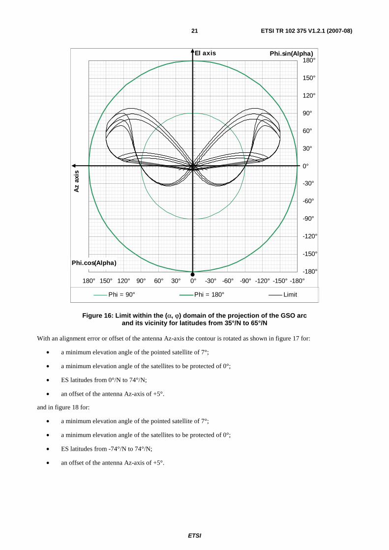
For an antenna designed for a limited range of latitudes, the GSO arc and its vicinity covers a smaller range within the off-axis angle domain (ϕ, α), as shown in figure 16 for:
• a minimum elevation angle of the pointed satellite of 7°;
• a minimum elevation angle of the satellites to be protected of 0°;
• ES latitudes from 35°/N to 65°/N.
ETSI
ETSI TR 102 375 V1.2.1 (2007-08) 21
-180°
-150°
-120°
-90°
-60°
-30°
0°
30°
60°
90°
120°
150°
180°
-180°-150°-120°-90°-60°-30°0°30°60°90°120°150°180°
Phi.cos(Alpha)
Phi.sin(Alpha)
Phi = 90° Phi = 180° Limit
El axis
Az
axis
Figure 16: Limit within the (α, ϕ) domain of the projection of the GSO arc and its vicinity for latitudes from 35°/N to 65°/N
With an alignment error or offset of the antenna Az-axis the contour is rotated as shown in figure 17 for:
• a minimum elevation angle of the pointed satellite of 7°;
• a minimum elevation angle of the satellites to be protected of 0°;
• ES latitudes from 0°/N to 74°/N;
• an offset of the antenna Az-axis of +5°.
and in figure 18 for:
• a minimum elevation angle of the pointed satellite of 7°;
• a minimum elevation angle of the satellites to be protected of 0°;
• ES latitudes from -74°/N to 74°/N;
• an offset of the antenna Az-axis of +5°.

ETSI
ETSI TR 102 375 V1.2.1 (2007-08) 22
-180°
-150°
-120°
-90°
-60°
-30°
0°
30°
60°
90°
120°
150°
180°
-180°-150°-120°-90°-60°-30°0°30°60°90°120°150°180°
Phi.cos(Alpha)
Phi.sin(Alpha)
Phi = 90° Phi = 180° Limit
El axis
Az
axis
Figure 17: Limit within the (α, ϕ) domain of the shadow of the GSO arc and its vicinity for latitudes from -74°/N to 74°/N and with an alignment offset of +5°

ETSI
ETSI TR 102 375 V1.2.1 (2007-08) 23
-180°
-150°
-120°
-90°
-60°
-30°
0°
30°
60°
90°
120°
150°
180°
-180°-150°-120°-90°-60°-30°0°30°60°90°120°150°180°
Phi.cos(Alpha)
Phi.sin(Alpha)
Phi = 90° Phi = 180° Limit
El axis
Az
axis
Figure 18: Limit within the (α, ϕ) domain of the shadow of the GSO arc and its vicinity for latitudes from 35°/N to 65°/N and with an alignment error of 5°
It is obvious that a permanent offset i of the Az-axis results in a rotation of i the contour. This is verified in figures 17 and 18.
For antennas which could be used up-side down, the contour has to be computed for offset i = 0° and for i = 180°.
It will be demonstrated that:
• For a antenna with an azimuth-elevation mount without GSO tangent alignment, designed for a maximum
elevation ,maxSEl and for a maximum vertical axis offset maxθ then the maximum value maxiδ of the
additional offset iδ of the antenna azimuth axis ,Az Suuuuur
, due to misalignment, is given by the following
equations:
- for ,max maxˆ0
2SElπ θ≤ ≤ − :
( )( )
max
max
,max
ˆsin
cos S
i ArcSinEl
θδ
⎛ ⎞⎜ ⎟=⎜ ⎟⎜ ⎟⎝ ⎠
(4a)
- for max ,maxˆ
2 2SElπ πθ− ≤ ≤ : max 2
i radπδ = (4b)

ETSI
ETSI TR 102 375 V1.2.1 (2007-08) 24
This value maxiδ is indirectly a function of the ES latitude and has to be added, for one extreme case, and subtracted,
for the other extreme case, to the permanent offset i for the computation of the GSO shadow on the antenna radiation pattern, for each ES latitude.
5.3.3 Azimuth-elevation antenna mount with GSO tangent alignment
5.3.3.1 General
An azimuth-elevation antenna mount with GSO tangent alignment capability consists of three axes:
• the antenna mount azimuth axis which is vertical;
• the antenna mount elevation axis which is horizontal;
• the antenna mount "attitude" axis which is parallel to the antenna main beam axis.
In the case of an azimuth-elevation antenna mount with GSO tangent alignment capability, the antenna orientation relative to the antenna mount elevation axis is adjustable for any direction of the antenna main beam axis.
Horizontal plane
Antenna mount Az-axis
Antenna mount El-axis
Antenna Az-axis
Antenna
Vertical
Antenna El-axis
Antenna mount attitude axis
Antenna main beam axis
Figure 19: Azimuth-elevation antenna mount with GSO tangent alignment
The antenna El-axis is set orthogonal to the GSO tangent. Figure 20 represents the visible part of GSO arc and its vicinity, the -3 dB contour of the antenna main beam and the relative position of the antenna azimuth and elevation axes for various satellite positions on the GSO arc.
In fact there is no practical means of knowing that such antenna is perfectly aligned with the GSO arc. This case is presented as the ideal case which gives the smallest (α, ϕ) domain of the GSO arc shadow on the antenna radiation pattern.
A practical case close to that ideal case consists of making the antenna polarizer fixed but on the antenna instead of being rotating as usual.
The ideal case is presented first, and then case of an antenna with a fixed polarizer is presented.

ETSI
ETSI TR 102 375 V1.2.1 (2007-08) 25
GSO
Horizon
-3 dB contour
Figure 20: GSO arc and -3 dB contour of the antenna main beam for various satellite positions
5.3.3.2 Ideal case
Figure 21 represents the GSO arc and its vicinity within the antenna (α, ϕ) domain for various ES latitudes and satellite positions on the GSO arc.
Table 2: Cases represented in figure 21
Case ES latitude Lg_S0 (1) 5,000°/N 74,313°/E (2) 30,000°/N 71,880°/E (3) 70,000°/N 38,046°/E (4) 30,000°/N -71,880°/E (5) 1,000°/N 0,744°/E
Case (5) corresponds to the case of an ES in the vicinity (e.g. at 138 km) of the sub-satellite point on the Earth.

ETSI
ETSI TR 102 375 V1.2.1 (2007-08) 26
-180°
-150°
-120°
-90°
-60°
-30°
0°
30°
60°
90°
120°
150°
180°
-180°
-150°
-120°
-90°-60°-30°0°30°60°90°120°150°180°Phi.cos(Alpha)
Phi.sin(Alpha)
GSO -3° GSO GSO +3° Phi = 90° Phi = 180°
El axis
Az
axis
El axis
Az
axis
El axis
Az
axis
El axis
Az
axis
El axis
Az
axis
El axis
Az
axis
(4)
(1)
(2)
(3)
(5)
Figure 21: GSO arc and its vicinity within the (α, ϕ) domain
The (α, ϕ) domain of the shadow of the GSO arc and its vicinity on the antenna radiation pattern is represented in figure 22 for:
• a minimum elevation angle of the pointed satellite of 7°;
• a minimum elevation angle of the satellites to be protected of 0°;
• ES latitudes from -74°/N to 74°/N.

ETSI
ETSI TR 102 375 V1.2.1 (2007-08) 27
-180°
-150°
-120°
-90°
-60°
-30°
0°
30°
60°
90°
120°
150°
180°
-180°-150°-120°-90°-60°-30°0°30°60°90°120°150°180°
Phi.cos(Alpha)
Phi.sin(Alpha)
Phi = 90° Phi = 180° Limit
El axis
Az
axis
Figure 22: Limit within the (α, ϕ) domain of the shadow of the GSO arc and its vicinity for latitudes from -74°/N to 74°/N
The above contour has been computed for 3 different latitudes of the adjacent satellite: -3°, 0° and +3°, using the method described for the Az-El antenna mount without GSO alignment.
With an alignment error or offset of the antenna Az-axis the contour is rotated as shown in figure 23 for:
• a minimum elevation angle of the pointed satellite of 7°;
• a minimum elevation angle of the satellites to be protected of 0°;
• ES latitudes from 0°/N to 74°/N;
• an offset of the antenna Az-axis of +5°.

ETSI
ETSI TR 102 375 V1.2.1 (2007-08) 28
-180°
-150°
-120°
-90°
-60°
-30°
0°
30°
60°
90°
120°
150°
180°
-180°-150°-120°-90°-60°-30°0°30°60°90°120°150°180°
Phi.cos(Alpha)
Phi.sin(Alpha)
Phi = 90° Phi = 180° Limit
El axis
Az
axis
Figure 23: Limit within the (α, ϕ) domain of the shadow of the GSO arc and its vicinity for latitudes from -74°/N to 74°/N and with an alignment error of 5°
It is obvious that a permanent offset i of the Az-axis result in a rotation of i the contour. This is verified in figure 23.
For antennas which could be used up-side down, the contour has to be computed for offset i = 0° and for i = 180°.
It will be demonstrated that:
• For a antenna with an azimuth-elevation mount with GSO tangent alignment the value of the additional offset
iδ of the antenna azimuth axis ,Az Suuuuur
is always equal to zero:
0iδ =
what ever are the values of the elevation and of the vertical axis offset.
5.3.3.3 Practical case of an antenna with a fixed polarizer
In that case the polarizer is not rotating but fixed, the two polarization planes rotate with the antenna and one of these two planes is aligned with the electric field received from the satellite.

ETSI
ETSI TR 102 375 V1.2.1 (2007-08) 29
In order to estimate the (α, ϕ) domain of the shadow of the GSO arc and its vicinity on the antenna radiation pattern the
satellite antenna is assumed to radiate an electric field 0Euur
and the associated magnetic field 0Huuur
in the direction of the
centre cS of the antenna beam coverage so that the direction of the received electric field ,r nEuuur
and the associated
magnetic field ,r nHuuuur
at station nS may be computed. The electric field 0Euur
may have a tilt angle (i_E0) with the pole
direction.
S
iE0
E0
H0
u0
Sc
Sn
un
Hr,n
Er,n
Figure 24: E and H fields at the satellite and at the ES
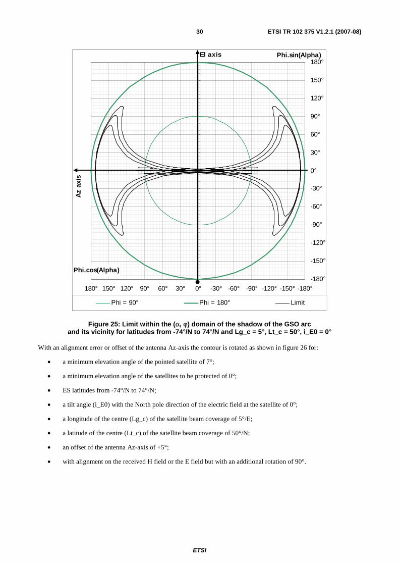
The (α, ϕ) domain of the shadow of the GSO arc and its vicinity on the antenna radiation pattern is represented in figure 25 for:
• a minimum elevation angle of the pointed satellite of 7°;
• a minimum elevation angle of the satellites to be protected of 0°;
• ES latitudes from -74°/N to 74°/N;
• a tilt angle (i_E0) with the North pole direction of the electric field at the satellite of 0°;
• a longitude of the centre (Lg_c) of the satellite beam coverage of 5°/E;
• a latitude of the centre (Lt_c) of the satellite beam coverage of 50°/N;
• with alignment on the received H field or the E field but with an additional rotation of 90°.
ETSI
ETSI TR 102 375 V1.2.1 (2007-08) 30
-180°
-150°
-120°
-90°
-60°
-30°
0°
30°
60°
90°
120°
150°
180°
-180°-150°-120°-90°-60°-30°0°30°60°90°120°150°180°
Phi.cos(Alpha)
Phi.sin(Alpha)
Phi = 90° Phi = 180° Limit
El axis
Az
axis
Figure 25: Limit within the (α, ϕ) domain of the shadow of the GSO arc and its vicinity for latitudes from -74°/N to 74°/N and Lg_c = 5°, Lt_c = 50°, i_E0 = 0°
With an alignment error or offset of the antenna Az-axis the contour is rotated as shown in figure 26 for:
• a minimum elevation angle of the pointed satellite of 7°;
• a minimum elevation angle of the satellites to be protected of 0°;
• ES latitudes from -74°/N to 74°/N;
• a tilt angle (i_E0) with the North pole direction of the electric field at the satellite of 0°;
• a longitude of the centre (Lg_c) of the satellite beam coverage of 5°/E;
• a latitude of the centre (Lt_c) of the satellite beam coverage of 50°/N;
• an offset of the antenna Az-axis of +5°;
• with alignment on the received H field or the E field but with an additional rotation of 90°.

ETSI
ETSI TR 102 375 V1.2.1 (2007-08) 31
-180°
-150°
-120°
-90°
-60°
-30°
0°
30°
60°
90°
120°
150°
180°
-180°-150°-120°-90°-60°-30°0°30°60°90°120°150°180°
Phi.cos(Alpha)
Phi.sin(Alpha)
Phi = 90° Phi = 180° Limit
El axis
Az
axis
Figure 26: Limit within the (α, ϕ) domain of the shadow of the GSO arc and its vicinity for latitudes from -74°/N to 74°/N, Lg_c = 5°, Lt_c = 50°, i_E0 = 0° and with an alignment error of 5°
It is obvious that a permanent offset i of the Az-axis result in a rotation of i the contour. This is verified in figure 27.
For antennas which could be used up-side down, the contour has to be computed for offset i = 0° and for i = 180°.
With a tilt angle of the electric field radiated by the satellite equal to 22°, as for Telecom 2 satellites in Ku band, the contour is no more ideal as shown in figure 27 for:
• a minimum elevation angle of the pointed satellite of 7°;
• a minimum elevation angle of the satellites to be protected of 0°;
• ES latitudes from -74°/N to 74°/N;
• a tilt angle (i_E0) with the North pole direction of the electric field at the satellite of 22°;
• a longitude of the centre (Lg_c) of the satellite beam coverage of 5°/E;
• a latitude of the centre (Lt_c) of the satellite beam coverage of 50°/N;
• no offset of the antenna Az-axis;
• with alignment on the received H field or the E field but with an additional rotation of 90°.

ETSI
ETSI TR 102 375 V1.2.1 (2007-08) 32
-180°
-150°
-120°
-90°
-60°
-30°
0°
30°
60°
90°
120°
150°
180°
-180°-150°-120°-90°-60°-30°0°30°60°90°120°150°180°
Phi.cos(Alpha)
Phi.sin(Alpha)
Phi = 90° Phi = 180° Limit
El axis
Az
axis
Figure 27: Limit within the (α, ϕ) domain of the shadow of the GSO arc and its vicinity for latitudes from -74°/N to 74°/N, Lg_c = 5°, Lt_c = 50°, i_E0 = 22° and with no alignment error
When the centre of the satellite beam coverage is not at the sub-satellite point on the Earth, as in the above example, this implies that the coverage area is limited to a portion of the visible part of the Earth from the satellite, and consequently that the range of operational latitudes of the ES is also limited to a smaller range than the range from -74°/N to 74°/N, in the above example.
When the range of operational latitudes of such antenna is limited to the range from 30°/N to 74°/N, with a tilt angle of the electric field radiated by the satellite equal to 22°, as for Telecom 2 satellites in Ku band, the contour is still close to the ideal contour but it is rotated as shown in figure 28 for:
• a minimum elevation angle of the pointed satellite of 7°;
• a minimum elevation angle of the satellites to be protected of 0°;
• ES latitudes from 30°/N to 74°/N;
• a tilt angle (i_E0) with the North pole direction of the electric field at the satellite of 22°;
• a longitude of the centre (Lg_c) of the satellite beam coverage of 5°/E;
• a latitude of the centre (Lt_c) of the satellite beam coverage of 50°/N;
• no offset of the antenna Az-axis;
• with alignment on the received H field or the E field but with an additional rotation of 90°.

ETSI
ETSI TR 102 375 V1.2.1 (2007-08) 33
-180°
-150°
-120°
-90°
-60°
-30°
0°
30°
60°
90°
120°
150°
180°
-180°-150°-120°-90°-60°-30°0°30°60°90°120°150°180°
Phi.cos(Alpha)
Phi.sin(Alpha)
Phi = 90° Phi = 180° Limit
El axis
Az
axis
Figure 28: Limit within the (α, ϕ) domain of the shadow of the GSO arc and its vicinity for latitudes from 30°/N to 74°/N, Lg_c = 5°, Lt_c = 50°, i_E0 = 22° and with no alignment error
Theses performances would be quite ideal if the antenna mount is fitted with a means of putting an offset equal to the electric field tilt angle as shown in figure 29 for:
• a minimum elevation angle of the pointed satellite of 7°;
• a minimum elevation angle of the satellites to be protected of 0°;
• ES latitudes from 30°/N to 74°/N;
• a tilt angle (i_E0) with the North pole direction of the electric field at the satellite of 22°;
• a longitude of the centre (Lg_c) of the satellite beam coverage of 5°/E;
• a latitude of the centre (Lt_c) of the satellite beam coverage of 50°/N;
• an offset of the antenna Az-axis of -22°;
• with alignment on the received H field or the E field but with an additional rotation of 90°.

ETSI
ETSI TR 102 375 V1.2.1 (2007-08) 34
-180°
-150°
-120°
-90°
-60°
-30°
0°
30°
60°
90°
120°
150°
180°
-180°-150°-120°-90°-60°-30°0°30°60°90°120°150°180°
Phi.cos(Alpha)
Phi.sin(Alpha)
Phi = 90° Phi = 180° Limit
El axis
Az
axis
Figure 29: Limit within the (α, ϕ) domain of the shadow of the GSO arc and its vicinity for latitudes from 30°/N to 74°/N, Lg_c = 5°, Lt_c = 50°, i_E0 = 22° and with an alignment offset of -22°
The tilt angle (i_E0) with the North Pole direction of the electric field at the satellite depends of the satellite and of the considered coverage and transmit frequency band. It is equal to 22° for Telecom 2 satellites. It seems that for some satellite operators the common values of the tilt angles is 0°, 3° or 7,5°, but it is not a general rule.
Presently, the values of the tilt angles seem to be not available in the satellite documentation published on the Web. Consequently the design of antenna using this technique of alignment with the GSO tangent is unsuitable for any satellite but could be suitable for a specific satellite or a series of satellites with the same value of the tilt angle, provided that the user is informed of that limitation, e.g. within the user documentation.
The value of the offset iδ of the antenna azimuth axis ,Az Suuuuur
is the sum of:
• the offset i_E0, if applied, for compensation of the tilt angle i_E0 of the electric field radiated by the satellite;
• the error 0Eiδ made in applying this offset;
• the error SPiδ due to a difference of orientation of the electric field radiated in the direction of the ES with the
electric field radiated in the direction of the centre of coverage;
• the error SnPiδ due to a difference of orientation of the polarization plane of the receive antenna in the satellite
direction but within the tracking or pointing contour of the antenna main beam with the polarization plane in the direction of the antenna main beam axis;

ETSI
ETSI TR 102 375 V1.2.1 (2007-08) 35
• the tracking or pointing alignment error P alignmentiδ made when aligning the antenna polarization plan with the
received electric field;
• the error ionosphere rainiδ + equal to the rotation angle of the received electric field through the ionosphere and through the atmosphere mainly when it is raining at the time of the alignment of the antenna polarization plan with the received electric field.
The error ionosphere rainiδ + is important in C-band and not negligible in Ku band during rainy conditions. For this reason:
• the initial alignment of the polarization plane of antennas receiving in Ku band with the GSO tangent should be performed during clear sky conditions;
• the alignment of the polarization plane of antennas receiving in Ku band with the GSO tangent should not be performed during rainy sky conditions, consequently the automatic and permanent alignment systems are unsuitable for these antennas;
• the alignment of the polarization plane of antennas receiving in C band with the GSO tangent is unsuitable for antennas receiving in C band.
For the use of such antennas, investigations have to be performed on the range of values of the above listed errors and on their effects on the contour.
5.3.4 Equatorial antenna mount
An equatorial antenna mount normally consists of one axis but is in fact in three axes:
• the antenna mount pole axis which is parallel to the Earth pole axis;
• the antenna mount azimuth axis which is vertical;
• the antenna mount elevation axis which is horizontal.
The antenna mount azimuth axis and elevation axis are used to give the correct orientation to the antenna mount pole axis. Once done, the antenna only rotates around the antenna mount pole axis.
Horizontal plane
Antenna mount Az-axis
Antenna mount El-axis
Antenna Az-axis Antenna
Vertical
Antenna El-axis
90° - Lt_n
Antenna mount pole-axis
Figure 30: Equatorial antenna mount

ETSI
ETSI TR 102 375 V1.2.1 (2007-08) 36
Figure 31 represents the GSO arc and its vicinity within the antenna (α, ϕ) domain for various ES latitudes and satellite positions on the GSO arc.
Table 3: Cases represented in figure 31
Case ES latitude Lg_S0 (1) 5,000°/N 74,313°/E (2) 30,000°/N 71,880°/E (3) 70,000°/N 38,046°/E (4) 30,000°/N -71,880°/E (5) 1,000°/N 0,744°/E
Case (5) corresponds to the case of an ES in the vicinity (e.g. at 138 km) of the sub-satellite point on the Earth.
-180°
-150°
-120°
-90°
-60°
-30°
0°
30°
60°
90°
120°
150°
180°
-180°-150°-120°-90°-60°-30°0°30°60°90°120°150°180°
Phi.cos(Alpha)
Phi.sin(Alpha)
GSO -3° GSO GSO +3° Phi = 90° Phi = 180°
El axis
Az
axis
El axis
Az
axis
El axis
Az
axis
El axis
Az
axis
El axis
Az
axis
El axis
Az
axis
(4)
(1)
(2)
(3)
(5)
Figure 31: GSO arc and its vicinity within the (α, ϕ) domain
The (α, ϕ) domain of the shadow of the GSO arc and its vicinity on the antenna radiation pattern is represented in figure 32 for:
• a minimum elevation angle of the pointed satellite of 7°;
• a minimum elevation angle of the satellites to be protected of 0°;
• ES latitudes from -74°/N to 74°/N.

ETSI
ETSI TR 102 375 V1.2.1 (2007-08) 37
-180°
-150°
-120°
-90°
-60°
-30°
0°
30°
60°
90°
120°
150°
180°
-180°-150°-120°-90°-60°-30°0°30°60°90°120°150°180°
Phi.cos(Alpha)
Phi.sin(Alpha)
Phi = 90° Phi = 180° Limit
El axis
Az
axis
Figure 32: Limit within the (α, ϕ) domain of the shadow of the GSO arc and its vicinity for latitudes from -74°/N to 74°/N
The above limit has been computed for 3 different latitudes of the adjacent satellite: -3°, 0° and +3°.
The above contour has been computed for 3 different latitudes of the adjacent satellite: -3°, 0° and +3°, using the method described for the Az-El antenna mount without GSO alignment.
With an alignment error or offset of the antenna Az-axis the contour is rotated as shown in figure 33 for:
• a minimum elevation angle of the pointed satellite of 7°;
• a minimum elevation angle of the satellites to be protected of 0°;
• ES latitudes from -74°/N to 74°/N;
• an offset of the antenna Az-axis of +5°.

ETSI
ETSI TR 102 375 V1.2.1 (2007-08) 38
-180°
-150°
-120°
-90°
-60°
-30°
0°
30°
60°
90°
120°
150°
180°
-180°-150°-120°-90°-60°-30°0°30°60°90°120°150°180°
Phi.cos(Alpha)
Phi.sin(Alpha)
Phi = 90° Phi = 180° Limit
El axis
Az
axis
Figure 33: Limit within the (α, ϕ) domain of the shadow of the GSO arc and its vicinity for latitudes from -74°/N to 74°/N and with an alignment error of 5°
It is obvious that a permanent offset i of the Az-axis result in a rotation of i the contour. This is verified in figure 33.
For antennas which could be used up-side down, the contour has to be computed for offset i = 0° and for i = 180°.
It will be demonstrated that:
• For a antenna with an equatorial mount the maximum value iΔ of the inclination error iδ of the antenna
azimuth axis ,Az Suuuuur
due to an error ,N nElδ on the elevation and to an error ,N nAzδ on the azimuth of the
estimated direction Nuur
of the North pole in a station nS at latitude nLt is given by the following relationship:
( ) ( )2 22
, ,,sin sin sin .cos .cos
2 2 2N n N n
n n N n
El AziLt Lt El
δ δδ⎛ ⎞ ⎛ ⎞Δ⎛ ⎞ = + +⎜ ⎟ ⎜ ⎟ ⎜ ⎟
⎝ ⎠ ⎝ ⎠ ⎝ ⎠ (5)
• When the latitude of the station is known with an accuracy highly better than iΔ , e.g. with a GPS, then the following relationship applies:
( ),sin sin .cos2 2
N nn
AziLt
δ⎛ ⎞Δ⎛ ⎞ = ⎜ ⎟⎜ ⎟⎝ ⎠ ⎝ ⎠
(6)

ETSI
ETSI TR 102 375 V1.2.1 (2007-08) 39
NOTE 1: A North-South error of 1 km on the location of the earth station corresponds to an error of 0,009° (= 360° x 1 km / 40 000 km) on the latitude of the earth station. This error is considered negligible for the antenna axis alignment. A GPS gives a better accuracy.
• For ESs designed to operate at any latitude, with the coordinates provided by a GPS, then the following relationship applies:
2 22, ,sin sin sin
2 2 2N n N nEl Azi δ δ⎛ ⎞ ⎛ ⎞Δ⎛ ⎞ = +⎜ ⎟ ⎜ ⎟ ⎜ ⎟
⎝ ⎠ ⎝ ⎠ ⎝ ⎠ (7)
Figure 34 shows the contour for:
• a minimum elevation angle of the pointed satellite of 7°;
• a minimum elevation angle of the satellites to be protected of 0°;
• ES latitudes from -74°/N to 74°/N;
• no offset of the antenna Az-axis;
• an error ,N nAzδon the azimuth of the estimated direction N
uur
of the North pole in the station of 4°;
• an error ,N nElδon the elevation of the estimated direction N
uur
of the North pole in the station of 3°.
NOTE 2: These values correspond to a global error angle between the North pole direction and its estimation of 5°
( )2 24 3 5+ = .

ETSI
ETSI TR 102 375 V1.2.1 (2007-08) 40
-180°
-150°
-120°
-90°
-60°
-30°
0°
30°
60°
90°
120°
150°
180°
-180°-150°-120°-90°-60°-30°0°30°60°90°120°150°180°
Phi.cos(Alpha)
Phi.sin(Alpha)
Phi = 90° Phi = 180° Limit
El axis
Az
axis
Figure 34: Limit within the (α, ϕ) domain of the shadow of the GSO arc and its vicinity for latitudes from -74°/N to 74°/N and with a pole axis alignment error of 5°
5.4 Minimum longitude offset The requirement for the protection of the other satellites of the GSO applies to adjacent satellites the longitudes of which are greater or equal to a minimum longitude offset (dLg_S_min).
To a minimum longitude offset (dLg_S_min) corresponds a minimum off-axis angle. The value of this minimum angle depends on the latitude of the ES and on the relative position of the pointed satellite.
In figure 35 the minimum off-axis angles are marked with red squares. Figure 35 corresponds to the case of alignment on the received electrical field:
• a minimum elevation angle of the pointed satellite of 7°;
• a minimum elevation angle of the satellites to be protected of 0°;
• ES latitudes from -74°/N to 74°/N;
• a tilt angle (i_E0) with the North pole direction of the electric field at the satellite of 22°;
• a longitude of the centre (Lg_c) of the satellite beam coverage of 5°/E;
• a latitude of the centre (Lt_c) of the satellite beam coverage of 50°/N;
• no offset of the antenna Az-axis;

ETSI
ETSI TR 102 375 V1.2.1 (2007-08) 41
• with alignment on the received H field or the E field but with an additional rotation of 90°;
• with alignment error of 1°;
• with a minimum longitude offset (dLg_S_min) of 3°.
A marker, represented by a dotted line, is used to determine the minimum size of the minimum off-axis angle. It is made of a straight line (Alpha = constant) a circle (Phi = constant) and a square with a side length equal to 2 × Phi and an inclination equal to Alpha.
-5°
-4°
-3°
-2°
-1°
0°
1°
2°
3°
4°
5°
-5°-4°-3°-2°-1°0°1°2°3°4°5°
Phi.cos(Alpha)
Phi.sin(Alpha)
GSO -3° GSO GSO +3° Marker dLg_S_min
El axis
Az
axis
Figure 35: Minimum off-axis angle within the (α, ϕ) domain of the shadow of the GSO arc and its vicinity for latitudes from -74°/N to 74°/N, Lg_c = 5°, Lt_c = 50°, i_E0 = 22°,
with alignment error of 1° and dLg_S_min = 3°
The minimum off-axis angles corresponding to the minimum longitude offset (dLg_S_min) have been computed for three adjacent satellite latitudes (-3°, 0° and +3°), and for following cases:
• the cases where the ES latitude varies from the minimum latitude to the maximum latitude, the ES antenna is pointed towards the satellite at the ES latitude, and the satellites to be protected are successively the East and West satellites at the minimum longitude offset (dLg_S_min);
• the cases where the ES latitude varies from the minimum latitude to the maximum latitude, the ES antenna is successively pointed towards the West and East satellites at the minimum elevation, and the satellites to be protected are successively the East and West satellites at the minimum longitude offset (dLg_S_min).
The smallest values of the minimum off-axis angles are obtained for the lowest elevation angles.

ETSI
ETSI TR 102 375 V1.2.1 (2007-08) 42
6 Mathematical analysis
6.1 Geographical coordinates See figure 36.
Y
Z North pole
R
S
O Lgn
dn
ρ
Sn
X
Vn Nn
Ltn
LgS
En
NS
ES
a
N
GSO
Figure 36: ES and satellite geographical coordinates
Let:
O: the centre of the Earth;
R: the mean Earth radius = 6 371 km (The Earth is assumed to be spherical.);
OZuuur
: the axis towards the North pole;
OXuuur
: the axis at the intersection of the Greenwich median plane and the Earth equatorial plan;
OYuuur
: the axis orthogonal to OXuuur
and OZuuur
axis towards the East;
Nuur
: the direction of the North pole.
Then:
0
0
1
X
N Y
Z
=⎧⎪= =⎨⎪ =⎩
uur
(8)

ETSI
ETSI TR 102 375 V1.2.1 (2007-08) 43
6.2 Earth station geographical coordinates Let:
nS : the earth station;
Lgn: the earth station longitude, positive towards the East;
Ltn: the earth station latitude, positive towards the North;
nVuur
: the vertical at station nS ;
nNuur
: the direction of the North at station nS ;
nEuur
: the direction of the East at station nS .
The Earth is assumed to be spherical.
Then:
( ) ( )( ) ( )( )
.cos .cos
.cos .sin
.sin
n n
n n n
n
X R Lt Lg
S Y R Lt Lg
Z R Lt
=⎧⎪
= =⎨⎪ =⎩
uur
(9)
( ) ( )( ) ( )( )
cos .cos
cos .sin
sin
n n
n n n
n
X Lt Lg
V Y Lt Lg
Z Lt
=⎧⎪
= =⎨⎪ =⎩
uur
(10)
( ) ( )( ) ( )
( )
sin .cos
sin .sin
cos
n n
n n n
n
X Lt Lg
N Y Lt Lg
Z Lt
= −⎧⎪
= = −⎨⎪ =⎩
uur
(11)
( )( )
sin
cos
0
n
n n
X Lg
E Y Lg
Z
= −⎧⎪
= =⎨⎪ =⎩
uur
(12)
. 0n nS N =
uur uur
. 0n nS E =
uur uur
.n n nS V S R= =
uur uur uur
(13)
6.3 Satellite geographical coordinates Let:
S: the satellite on the GSO, or within its vicinity;
ρ: the nominal GSO radius = 42 164 km, and also radius the sphere of the GSO vicinity;
LgS: the satellite longitude, positive towards the East;

ETSI
ETSI TR 102 375 V1.2.1 (2007-08) 44
LtS: the satellite latitude, positive towards the North;
SNuuur
: the direction of the North at the satellite S position. This direction is different of the North Pole direction when the latitude of the satellite is not equal to 0;
SEuur
: the direction of tangent to the GSO towards the East at the satellite S position.
Then:
( ) ( )( ) ( )( )
.cos .cos
.cos .sin
.sin
S S
S S
S
X Lt Lg
S Y Lt Lg
Z Lt
ρρρ
=⎧⎪
= =⎨⎪ =⎩
ur
(14)
( ) ( )( ) ( )
( )
sin .cos
sin .sin
cos
S S
S S S
S
X Lt Lg
N Y Lt Lg
Z Lt
= −⎧⎪
= = −⎨⎪ =⎩
uuur
(15)
( )( )
sin
cos
0
S
S S
X Lg
E Y Lg
Z
= −⎧⎪
= =⎨⎪ =⎩
uur
(16)
. 0SS N =
ur uuur
. 0SS E =
ur uur
(17)
6.4 Local coordinates
S
Sn
South Azn
ElS
GSO
z
x
Vn
En
North
y
Zenith
Figure 37: ES and satellite geographical coordinates

ETSI
ETSI TR 102 375 V1.2.1 (2007-08) 45
Let:
nS : the earth station;
Oxuur
: the axis towards the local South at station nS ;
NOTE: The GSO arc is mainly southwards for a station on the north hemisphere but it is northwards for a station on the south hemisphere.
Oyuur
: the axis towards the local East at station nS ;
Ozuur
: the vertical axis at station nS ;
AzD: the azimuth of a considered direction Dur
;
ElD: the elevation of a considered direction Dur
;
nVuur
: the vertical at station nS ;
nNuur
: the direction of the North at station nS ;
nEuur
: the direction of the East at station nS ;
M : a point of the space with geographical coordinates ( ), ,M M MX Y Z and local coordinates
( ), ,M M Mx y z ;
Md the distance from nS to M .
Then:
0
0
1n
x
V y
z
=⎧⎪= =⎨⎪ =⎩
uur
1
0
0n
x
N y
z
= −⎧⎪= =⎨⎪ =⎩
uur
0
1
0n
x
E y
z
=⎧⎪= =⎨⎪ =⎩
uur
M nd S M=
uuuuur
(18)
( ) ( )( ) ( )( )
.cos .cos
.cos .sin
.sin
M M M M
n M M M M
M M M
x d El Az
S M y d El Az
z d El
= −⎧⎪
= =⎨⎪ =⎩
uuuuur
(19)
( ). . . .
. . . .
. . . .
M n n n n n n
n M n n n n n n
M n n n n n n
x S M N M N S N M N
S M y S M E M E S E M E
z S M V M V S V M V R
⎧ = − = − − = −⎪⎪= = = − =⎨⎪ = = − = −⎪⎩
uuuuur uur uur uur uur uur uur uur
uuuuur uuuuur uur uur uur uur uur uur uur
uuuuur uur uur uur uur uur uur uur
(20)
( ) ( ) ( ) ( ) ( )( ) ( )
( ) ( ) ( ) ( ) ( )
.sin .cos .sin .sin .cos
.sin .cos
.cos .cos .cos .sin .sin
M M n n M n n M n
n M M n M n
M M n n M n n M n
x X Lt Lg Y Lt Lg Z Lt
S M y X Lg Y Lg
z X Lt Lg Y Lt Lg Z Lt R
= + −⎧⎪
= = − +⎨⎪ = + + −⎩
uuuuur
(21)
ETSI
ETSI TR 102 375 V1.2.1 (2007-08) 46
( ) ( ) ( )( ) ( ) ( ) ( )
( ) ( ) ( )( ) ( ) ( ) ( )
( ) ( ) ( )
.sin .cos .sin
.cos .cos .cos .cos
.sin .sin .cos
.cos .sin .cos .sin
.cos .sin .sin
M n n M n
M
M n n n n
M n n M n
n M
M n n n n
M M n M n n
x Lt Lg y LgX
z Lt Lg R Lt Lg
x Lt Lg y LgS M Y
z Lt Lg R Lt Lg
Z x Lt z Lt R Lt
⎧ + −⎛ ⎞=⎪ ⎜ ⎟⎜ ⎟+ −⎪ ⎝ ⎠
⎪+ +⎛ ⎞⎪= = ⎜ ⎟⎨ ⎜ ⎟+ −⎪ ⎝ ⎠
⎪ = − + +⎪⎪⎩
uuuuur
(22)
For any vector n nAB S B S A= −uuur uuuur uuuur
the above two sets of equations for the transformation of geographical coordinates
into local coordinates and conversely are applicable for 0R = due to the fact that the coordinates of ABuuur
are the differences of absolutes coordinates.
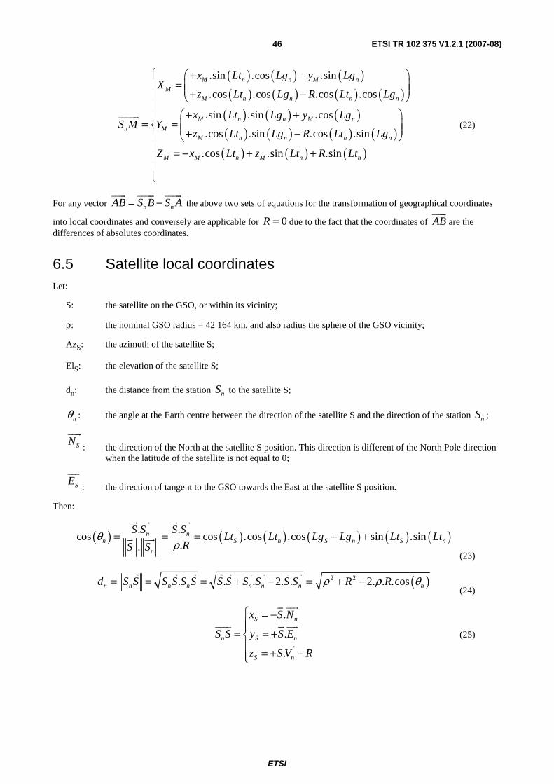
6.5 Satellite local coordinates Let:
S: the satellite on the GSO, or within its vicinity;
ρ: the nominal GSO radius = 42 164 km, and also radius the sphere of the GSO vicinity;
AzS: the azimuth of the satellite S;
ElS: the elevation of the satellite S;
dn: the distance from the station nS to the satellite S;
nθ : the angle at the Earth centre between the direction of the satellite S and the direction of the station nS ;
SNuuur
: the direction of the North at the satellite S position. This direction is different of the North Pole direction when the latitude of the satellite is not equal to 0;
SEuur
: the direction of tangent to the GSO towards the East at the satellite S position.
Then:
( ) ( ) ( ) ( ) ( ) ( ). .cos cos .cos .cos sin .sin
..n n
n S n S n S n
n
S S S SLt Lt Lg Lg Lt Lt
RS Sθ
ρ= = = − +
ur uur ur uur
ur uur
(23)
( )2 2. . . 2. . 2. . .cosn n n n n n n nd S S S S S S S S S S S S R Rρ ρ θ= = = + − = + −
uuur uuur uuur ur ur uur uur ur uur
(24)
.
.
.
S n
n S n
S n
x S N
S S y S E
z S V R
⎧ = −⎪⎪= = +⎨⎪ = + −⎪⎩
ur uur
uuur ur uur
ur uur
(25)

ETSI
ETSI TR 102 375 V1.2.1 (2007-08) 47
( ) ( ) ( ) ( ) ( )( ) ( )( ) ( ) ( ) ( ) ( )
. cos .sin .cos sin .cos
. cos .sin
. cos .cos .cos sin .sin
S S n S n S n
n S S S n
S S n S n S n
x Lt Lt Lg Lg Lt Lt
S S y Lt Lg Lg
z Lt Lt Lg Lg Lt Lt R
ρ
ρ
ρ
⎧ = − −⎡ ⎤⎣ ⎦⎪⎪= = −⎡ ⎤⎨ ⎣ ⎦⎪
= − + −⎡ ⎤⎪ ⎣ ⎦⎩
uuur
(26)
( ) ( )( ) ( )( )
.cos .cos
.cos .sin
.sin
S n S S
n S n S S
S n S
x d El Az
S S y d El Az
z d El
= −⎧⎪
= =⎨⎪ =⎩
uuur
(27)
6.6 Other relationships between Satellite and ES coordinates Let:
an: the aspect angle from the satellite S between the direction of the Earth centre O and the direction of the station
nS .
S O
θn
Eln
Sn dn R
an
ρ
Vn
Figure 38: Triangle (0, S, nS )
Within the triangle (0, S, nS ) the following relationships exist:
( ) ( )sinsin sin2 n
n n
n
Ela
d R
πθ
ρ
⎛ ⎞+⎜ ⎟⎝ ⎠ = =
or:
( ) ( ) ( )cos sin sinn n n
n
El a
d R
θρ
= = (28)
( ) ( ) ( ) ( ) ( ) ( ).cos cos .cos .cos sin .sin
.n
n S n S n S n
S SLt Lt Lg Lg Lt Lt
Rθ
ρ= = − +
r r
(29)
( )2 2 2 2. . .cosn nd R Rρ ρ θ= + −
(30)
Then for a given satellite S and a given earth station nS the elevation Eln of the satellite in station nS may be
determined with the following formulae:
( ) ( )( )2 2
.cos.sin
2. . .cos
nn nn
n n
RS S VEl
S S R R
ρ θρ ρ θ
−= =
+ −
uuur r
uuur
(31)
( ) ( )
( ) ( ) ( )( ) ( )
( )2 2
sin .cos .cos.
cos .sin.cos .cos
2. . .cos
n S S n
n Sn n Sn n
nn
Lt Lt Lg Lg
Lt LtS S N xEl Az
dS S R R
ρ
ρ ρ θ
+ −⎛ ⎞⎜ ⎟⎜ ⎟−⎝ ⎠= = − = −
+ −
uuur r
uuur (32)

ETSI
ETSI TR 102 375 V1.2.1 (2007-08) 48
( ) ( ) ( ) ( )( )2 2
.cos .sin.cos .sin
2. . .cos
S S nn n Sn n
nn
Lt Lg LgS S E yEl Az
dS S R R
ρρ ρ θ
−= = =
+ −
uuur r
uuur (33)
( )2 , 2 ,S Sn S S
n n
y xAz ArcTan ArcTan y x
d d
⎛ ⎞= − = −⎜ ⎟
⎝ ⎠ (34)
with:
( ) ( )( ) [ [2 .sin , .cos 0 ,ArcTan a x a x x for a and x π π= > ∈ − + (35)
( )( ) ( ) ( )( ) ( )
sin .cos2 sin ,
tan .cos
n S n
n S n
S n
Lt Lg LgAz ArcTan Lg Lg
Lt Lt
⎛ ⎞− −⎛ ⎞= ⎜ − ⎟⎜ ⎟⎜ ⎟⎜ ⎟+⎝ ⎠⎝ ⎠ (36)
The satellite longitude LgS corresponding to a given elevation Eln is a solution of the following equations:
( ) ( )
( )( ) ( ) ( ) ( ) ( ) ( )
2 2
.cossin
2. . .cos
cos cos .cos .cos sin .sin
nn
n
n S n S n S n
REl
R R
Lt Lt Lg Lg Lt Lt
ρ θρ ρ θ
θ
−⎧=⎪
+ −⎨⎪ = − +⎩
(37)
or:
( ) ( )( ) ( ) ( ) ( )( )( ) ( ) ( ) ( )
( ) ( )
2 2 2 22 2 2.cos 2. . .cos .cos .sin .cos 0
cos sin .sincos
cos .cos
n n n n n
n S nS n
S n
R El El R El
Lt LtLg Lg
Lt Lt
ρ θ ρ θ ρ
θ
⎧ − − − =⎪⎪⎨ −
− =⎪⎪⎩
(38)
The discriminant Δ of the above 2nd degree equation of ( )cos nθ is:
( ) ( )( )2 22 2 24. .sin . .cosn nEl R Elρ ρΔ = +
(39)
Two values of ( )cos nθ are obtained:
( ) ( ) ( ) ( )2
2 2cos .cos sin . 1 .cosn n n n
R REl El Elθ
ρ ρ⎛ ⎞ ⎛ ⎞= ± −⎜ ⎟ ⎜ ⎟⎝ ⎠ ⎝ ⎠ (40)
The larger values of ( )cos nθ corresponds to an earth station visible from the satellite, the other value to an earth
station hidden by the Earth as shown in figure 39.

ETSI
ETSI TR 102 375 V1.2.1 (2007-08) 49
S O θn
Eln
Sn
dn R
ρ
Sn' Eln
θn'
R.Cos(θn) R.Cos(θn')
Figure 39: Triangle (0, S, nS )
Then:
( ) ( ) ( ) ( )
( ) ( ) ( ) ( )( ) ( )
22 2
cos .cos sin . 1 .cos
cos sin .sincos
cos .cos
n n n n
n S nS n
S n
R REl El El
Lt LtLg Lg
Lt Lt
θρ ρ
θ
⎧ ⎛ ⎞ ⎛ ⎞⎪ = + −⎜ ⎟ ⎜ ⎟⎪ ⎝ ⎠ ⎝ ⎠⎨
−⎪ − =⎪⎩
(41)
The maximum satellite latitude Ltn, max corresponding to a given elevation Eln is solution of the following equations:
( ) ( ) ( ) ( )
( ) ( ) ( ) ( )( ) ( )
22 2
,max
,max
cos .cos sin . 1 .cos
cos sin .sincos
cos .cos
n n n n
n S n
S nS n
S n
R REl El El
Lt LtLg Lg
Lt Lt
Lg Lg
θρ ρ
θ
⎧ ⎛ ⎞ ⎛ ⎞⎪ = + −⎜ ⎟ ⎜ ⎟⎪ ⎝ ⎠ ⎝ ⎠⎪
−⎪⎪ − =⎨⎪⎪ =⎪⎪⎪⎩
(42)
or:
( ) ( ) ( ) ( )2
2 2
,maxcos .cos sin . 1 .cosS n n n n
R RLt Lt El El El
ρ ρ⎛ ⎞ ⎛ ⎞− = + −⎜ ⎟ ⎜ ⎟⎝ ⎠ ⎝ ⎠ (43)
6.7 Antenna Cartesian coordinates
S
Sn
North
Azn
Eln
z
x
Vn
uAz,S
uR,S
uEl,S uAz,S
uR,S
uEl,S
LS,n
TS,n
y
En
Za
ya xa
i
Figure 40: Antenna Cartesian coordinates
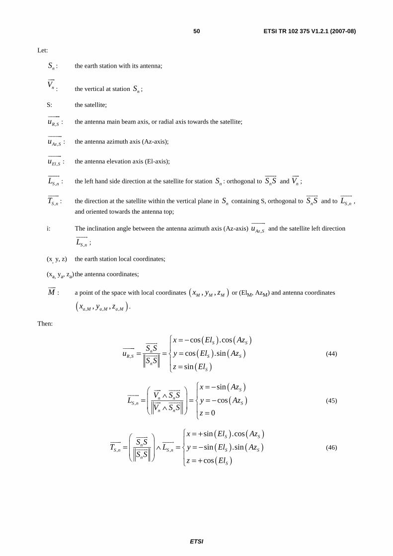
ETSI
ETSI TR 102 375 V1.2.1 (2007-08) 50
Let:
nS : the earth station with its antenna;
nVuur
: the vertical at station nS ;
S: the satellite;
,R Suuuuur
: the antenna main beam axis, or radial axis towards the satellite;
,Az Suuuuur
: the antenna azimuth axis (Az-axis);
,El Suuuuur
: the antenna elevation axis (El-axis);
,S nLuuur
: the left hand side direction at the satellite for station nS : orthogonal to nS Suuur
and nVuur
;
,S nTuuur
: the direction at the satellite within the vertical plane in nS containing S, orthogonal to nS Suuur
and to ,S nLuuur
,
and oriented towards the antenna top;
i: The inclination angle between the antenna azimuth axis (Az-axis) ,Az Suuuuur
and the satellite left direction
,S nLuuur
;
(x, y, z) the earth station local coordinates;
(xa, ya, za) the antenna coordinates;
Muur
: a point of the space with local coordinates ( ), ,M M Mx y z or (ElM, AzM) and antenna coordinates
( ), , ,, ,a M a M a Mx y z .
Then:
( ) ( )( ) ( )( )
,
cos .cos
cos .sin
sin
S S
nR S S S
nS
x El AzS S
u y El AzS S
z El
= −⎧⎪
= = =⎨⎪ =⎩
uuur
uuuur
uuur (44)
( )( ),
sin
cos
0
S
n nS n S
n n
x AzV S S
L y AzV S S
z
= −⎧⎛ ⎞ ⎪∧⎜ ⎟= = = −⎨⎜ ⎟∧ ⎪⎝ ⎠ =⎩
uur uuur
uuur
uur uuur (45)
( ) ( )( ) ( )( )
, ,
sin .cos
sin .sin
cos
S S
nS n S n S S
nS
x El AzS S
T L y El AzS S
z El
= +⎧⎛ ⎞ ⎪⎜ ⎟= ∧ = = −⎨⎜ ⎟ ⎪⎝ ⎠ = +⎩
uuur
uuur uuur
uuur (46)

ETSI
ETSI TR 102 375 V1.2.1 (2007-08) 51
LS,n
Y
Z Sn
Earth
Figure 41: Satellite left hand side direction ,S nLuuur
for a station Sn,
seen from the satellite
As shown in figure 41, the satellite left hand side direction for a ES Sn is towards the East when the ES is located in the
north hemisphere and in the meridian plan of the satellite, otherwise any other direction is possible. The variations of that direction are continuous except at the sub-satellite point on the Earth along any line passing by that point and where the discontinuity at this point is equal to ±180°. The use of the satellite left hand side direction for a ES Sn is suitable for
antennas which are rotated by 180° in azimuth when crossing the equator from one position to the position symmetrical to the sub-satellite point and when pointing the same satellite, and:
( ) ( )( ) ( ) ( ) ( ) ( )( ) ( ) ( ) ( ) ( )
( ) ( ), , ,
cos .sin sin .sin .cos
cos . sin . cos .cos sin .sin .sin
sin .cos
S S S
Az S S n S n S S S
S
x i Az i El Az
u i L i T y i Az i El Az
z i El
= − +⎧⎪
= + = = − −⎨⎪ = +⎩
uuuur uuur uuur
(47)
( ) ( )( ) ( ) ( ) ( ) ( )( ) ( ) ( ) ( ) ( )
( ) ( ), , ,
sin .sin cos .sin .cos
sin . cos . sin .cos cos .sin .sin
cos .cos
S S S
El S S n S n S S S
S
x i Az i El Az
u i L i T y i Az i El Az
z i El
= + +⎧⎪
= − + = = + −⎨⎪ = +⎩
uuuur uuur uuur
(48)
( ) ( )( ) ( )( )
cos .cos
cos .sin
sin
M M
n M M
M
x El Az
S M y El Az
z El
= −⎧⎪
= =⎨⎪ =⎩
uuuuur
(49)
( ) ( ) ( )( ) ( ) ( )( ) ( ) ( ) ( )
, ,
sin .sin .cos
. cos .cos .sin
sin .cos .sin .cos
M S
a M n Az S M S M
M S S M
i El El
x S M u i El Az Az
i El El Az Az
+⎛ ⎞⎜ ⎟
= = + −⎜ ⎟⎜ ⎟− −⎝ ⎠
uuuuur uuuur
(50)
( ) ( ) ( )( ) ( ) ( ) ( )( ) ( ) ( )
, ,
sin .cos .sin
. cos .sin .cos .cos
cos .cos .sin
M S M
a M n El S S M S M
S M
i El Az Az
y S M u i El El Az Az
i El El
− −⎛ ⎞⎜ ⎟
= = − −⎜ ⎟⎜ ⎟+⎝ ⎠
uuuuur uuuur
(51)
( ) ( ) ( ) ( ) ( ), ,. cos .cos .cos sin .sina M n R S S M S M S Mz S M u El El Az Az El El= = − +uuuuur uuuur
(52)

ETSI
ETSI TR 102 375 V1.2.1 (2007-08) 52
6.8 Antenna polar coordinates Two types of polar coordinates are used:
• one is used to describe the North-South and East-West variations (ϕEl and ϕAz) from the main beam axis as it
could be seen by an observer at the antenna location;
• the other describe the antenna radiation patterns, with the angle α of the plan containing the main beam axis and the direction to the considered point M and the off-axis angle ϕ of the direction of M from the main beam axis.
Antenna Az axis
Antenna El axis Main beam axis
za
xa
ya
ϕAz ϕEl
M
Sn
Figure 42: Off-axis angles ϕEl and ϕAz of a direction nS Muuuuur
Antenna El axis Antenna Az axis
Main beam axis
ϕ
α
M
ya
xa
za
Sn
ϕAz
ϕEl
Figure 43: Off-axis angles (ϕ), and α angle of a direction nS Muuuuur

ETSI
ETSI TR 102 375 V1.2.1 (2007-08) 53
Let:
nS : the earth station with its antenna;
M : a point of the space (ElM, AzM) and antenna coordinates;
α M: the angle of the projection of the direction of M on the plane orthogonal to the antenna main beam axis
with the antenna azimuth axis (Az-axis); and
ϕ M: the off-axis angle of the direction of M with the antenna main beam direction;
ϕ El: the angle of the direction of M with the plane defined by the antenna main beam axis and the antenna
azimuth axis (Az-axis);
ϕ Az: the angle of the projection of the direction of M on the plane define by the antenna main beam axis and
the antenna azimuth axis (Az-axis) with the antenna main beam axis.
Then:
( ) ( )( )( ) ( )
cos .sin
sin
cos .cos
a El Az
n a El
a El Az
x
S M y
z
ϕ ϕϕϕ ϕ
=⎧⎪
= =⎨⎪ =⎩
uuuuur
(53)
( ) ( )( ) ( )( )
sin .cos
sin .sin
cos
a M M
n a M M
a M
x
S M y
z
ϕ αϕ αϕ
=⎧⎪
= =⎨⎪ =⎩
uuuuur
(54)
and:
( )El aArcSin yϕ =
(55)
( )2 ,Az a aArcTan x zϕ =
(56)
( ) ( ) ( )( ), cos .cosM a M El AzArcCos z ArcCosϕ ϕ ϕ= =
(57)
( ) ( )( ) ( )( )
( ) ( ) ( )( ) ( )( )
2 ,sin sin
2 , . sin
2 sin ,cos .sin . sin
a a
M M
M a a M
El El Az M
y xArcTan
ArcTan y x rad
ArcTan rad
ϕ ϕ
α π ϕ
ϕ ϕ ϕ π ϕ
⎧ ⎛ ⎞=⎪ ⎜ ⎟⎜ ⎟
⎪ ⎝ ⎠⎪= = + ϒ −⎨⎪
= + ϒ −⎪⎪⎩
(58)
( )0 180 0 sin 1M Azϕ ϕ° ≤ ≤ ° ⇒ ≤ ≤ (59)
( ) ( ) ( )( )2 sin ,cos .sinM El El AzArcTanα ϕ ϕ ϕ=
(60)

ETSI
ETSI TR 102 375 V1.2.1 (2007-08) 54
6.9 Antenna Az-axis alignment
S
Sn
Nn
z
x
Vn
uAz,S
uR,S
uEl,S LS,n
TS,n
y
En
Za
ya xa
i
NS
N ES
Earth
GSO
Figure 44a: Antenna Cartesian coordinates
Y
Z North pole
S
O
Sn
X
Vn Nn
En
ES
N
LS,n
TS,n N NS
N
GSO
Figure 44b: Antenna Cartesian coordinates
Let:
nS : the earth station with its antenna;
nVuur
: the vertical at station nS ;
nNuur
: the direction of the North at station nS ;
nEuur
: the direction of the East at station nS ;
S: the satellite;
SNuuur
: the direction of the North at the satellite S position and orthogonal to OSuuur
;

ETSI
ETSI TR 102 375 V1.2.1 (2007-08) 55
SEuur
: the direction of tangent to the GSO towards the East at the satellite S position, orthogonal to OSuuur
and
SNuuur
;
,R Suuuuur
: the antenna main beam axis, or radial axis towards the satellite;
,Az Suuuuur
: the antenna azimuth axis (Az-axis);
,El Suuuuur
: the axis antenna elevation axis (El-axis);
,S nLuuur
: the left hand side direction at the satellite for station nS , orthogonal to nS Suuur
and nVuur
;
,S nTuuur
: the direction at the satellite within the vertical plane in nS containing S, orthogonal to nS Suuur
and to ,S nLuuur
,
and oriented towards the antenna top;
i: the inclination angle between the antenna azimuth axis (Az-axis) ,Az Suuuuur
and the left hand side direction
,S nLuuur
of the satellite for station #n;
iAz: the inclination angle between the ,Az Suuuuur
and ,S nLuuur
or between the ,El Suuuuur
and ,S nTuuur
with the antenna
mount;
(x, y, z) the earth station local coordinates;
(xa, ya, za) the antenna coordinates.
Then:
,S n
El S
S n
E S Su
E S S
∧∧
uur uuur
uuuur
uur uuur
(61)
( ), ,,S El S S ni angle u T=uuuur uuur
(62)
The values of ( )sin Si may be obtained from the following set of equations:
( ) ( ) ( ) ( ) ( )( ) ( )( ) ( ) ( ) ( ) ( )
. cos .sin .cos sin .cos
. cos .sin
. cos .cos .cos sin .sin
S S n S n S n
n S S S n
S S n S n S n
x Lt Lt Lg Lg Lt Lt
S S y Lt Lg Lg
z Lt Lt Lg Lg Lt Lt R
ρ
ρ
ρ
⎧ = − −⎡ ⎤⎣ ⎦⎪⎪= = −⎡ ⎤⎨ ⎣ ⎦⎪
= − + −⎡ ⎤⎪ ⎣ ⎦⎩
uuur
(63)
0
0
1n
x
V y
z
=⎧⎪= =⎨⎪ =⎩
uur
(64)
,n n
S n
n n
V S SL
V S S
⎛ ⎞∧⎜ ⎟=⎜ ⎟∧⎝ ⎠
uur uuur
uuur
uur uuur (65)

ETSI
ETSI TR 102 375 V1.2.1 (2007-08) 56
, ,n
S n S n
n
S ST L
S S
⎛ ⎞⎜ ⎟= ∧⎜ ⎟⎝ ⎠
uuur
uuur uuur
uuur (66)
( ) ( )( )
( ) ( )
sin .sin
cos
cos .sin
n S n
S S n
n S n
x Lt Lg Lg
E y Lg Lg
z Lt Lg Lg
= − −⎧⎪
= = −⎨⎪ = − −⎩
uur
(67)
,S n
El S
S n
E S Su
E S S
∧∧
uur uuur
uuuur
uur uuur
(68)
( ), ,,Az El S S ni angle u T=uuuur uuur
(69)
uAz,S
LS,n
TS,n
iAz
uEl,S
iAz
Figure 45: Projections of ,El Suuuuur
on ,S nLuuur
and ,S nTuuur
( )( )
( ) ( )( ), ,
, ,
cos .2 sin ,cos
sin .
Az El S S n
Az Az Az
Az El S S n
i u Ti ArcTan i i
i u L
⎧ ⎫=⎪ ⎪⇒ =⎨ ⎬
= −⎪ ⎪⎩ ⎭
uuuur uuur
uuuur uuur (70)
The antenna azimuth axis (Az-axis) is aligned with the tangent to the GSO arc at the satellite S position when:
Azi i= − .
6.10 Az-axis alignment of an antenna with a fixed polarizer Let:
S: the satellite;
cS : the centre of the satellite beam coverage on the Earth;
nS : the earth station with its antenna;
nVuur
: the vertical at station nS ;
Nuur
: the direction of the North pole;
nuuur
: the direction of station nS from the satellite;
cuuur
: the direction of the centre cS of the satellite beam coverage on the Earth from the satellite;

ETSI
ETSI TR 102 375 V1.2.1 (2007-08) 57
,S nLuuur
: the left hand side direction at the satellite for station nS , orthogonal to nS Suuur
and nVuur
;
,S cEuuuur
: the direction towards the East at the satellite: orthogonal to cSSuuur
and Nuur
;
0Euur
: the radiated electric field at the satellite;
0Huuur
: the radiated magnetic field at the satellite;
0Z : the vacuum impedance: 00
0
120. 376,6Zμ πε
= = = Ω ;
0Ei : the tilt angle of radiated electric field at the satellite relative to the North pole direction Nuur
;
,r nEuuur
: the received electric field at station #n;
,r nHuuuur
: the received magnetic field at station #n;
i: the inclination angle between the antenna azimuth axis (Az-axis) ,Az Suuuuur
and the left hand side direction
,S nLuuur
of the satellite for station #n;
iE: the inclination angle between the received electric field ,r nEuuur
or magnetic field ,r nHuuuur
and ,S nLuuur
.
Then:
nn
n
SSu
SS
uuur
uur
uuur (71)
cc
c
SSu
SS
uuur
uur
uuur (72)
,n n
S n
n n
SS VL
SS V
∧=∧
uuur uur
uuur
uuur uur (73)
,c
S c
c
SS NE
SS N
∧=∧
uuur uur
uuuur
uuur uur
(74)
( ) ( )0 00 ,= cos . +sin .E E S cE i N i E
uur uur uuuur
(75)
0 0 0. cZ H u E= ∧uuur uur uur
(76)
( ) ( )( ) ( )
0 0 0
,
0 0 0
.
.
n n n
r n
n n n
u E u Z H uE
u E u Z H u
∧ ∧ + ∧=
∧ ∧ + ∧
uur uur uur uuur uur
uuur
uur uur uur uuur uur
(77)
0 , ,. r n n r nZ H u E= ∧uuuur uur uuur
(78)

ETSI
ETSI TR 102 375 V1.2.1 (2007-08) 58
When the antenna Az-axis is aligned on the received electric field:
( )
( )
, , , ,, ,
, ,, , , ,
cos . . sin2
sin . . cos2
E S n Az S S n r n EAz S r n
El S r nE S n Az S S n r n E
i L u L E iu E
u H i T u T E i
π
π
⎧ ⎛ ⎞+ = = = −⎜ ⎟⎪⎧ ⎫=⎪ ⎪ ⎪ ⎝ ⎠⇒⎨ ⎬ ⎨
⎛ ⎞= −⎪ ⎪ ⎪⎩ ⎭ + = = =⎜ ⎟⎪ ⎝ ⎠⎩
uuur uuuur uuur uuur
uuuur uuur
uuuur uuuur
uuur uuuur uuur uuur
(79)
When the antenna Az-axis is aligned on the received magnetic field:
( )( )
, , , , , ,
, , , , , ,
cos . .
sin . .
Az S r n E S n Az S S n r n
El S r n E S n Az S S n r n
u H i L u L H
u E i T u T H
⎧ ⎫ ⎧= = =⎪ ⎪ ⎪⇒⎨ ⎬ ⎨
= = =⎪ ⎪ ⎪⎩ ⎭ ⎩
uuuur uuuur uuur uuuur uuur uuuur
uuuur uuur uuur uuuur uuur uuuur (80)
( ) ( )( )2 sin ,cosE E Ei ArcTan i i= (81)
The antenna azimuth axis (Az-axis) is aligned with the received electric field ,r nEuuur
or magnetic field ,r nHuuuur
from
satellite S when: Ei i= − .
6.11 Antenna with equatorial mount
N
Vn
O
Sn
S LS,n
TS,n
N N
Vn
O
Sn
S
uAz,S
uEl,S
N
GSO GSO
Figure 46: Antenna Cartesian coordinate systems relative to the local vertical direction and relative to the Pole axis
Let:
nS : the earth station with its antenna;
nVuur
: the vertical at station nS ;
S: the satellite;
,Az Suuuuur
: the antenna azimuth axis (Az-axis);
,El Suuuuur
: the axis antenna elevation axis (El-axis);
Nuur
: the direction of the North;
SNuuur
: the direction of the North at the satellite S position and orthogonal to OSuuur
;

ETSI
ETSI TR 102 375 V1.2.1 (2007-08) 59
SEuur
: the direction of tangent to the GSO towards the East at the satellite S position, orthogonal to OSuuur
and
SNuuur
;
,S nLuuur
: the left hand side direction at the satellite for station nS : orthogonal to nS Suuur
and nVuur
;
,S nTuuur
: the direction at the satellite within the vertical plane in nS containing S, orthogonal to nS Suuur
and to ,S nLuuur
,
and oriented towards the North;
i: the inclination angle between the antenna azimuth axis (Az-axis) ,Az Suuuuur
and the left hand side direction
,S nLuuur
of the satellite for station #n;
iEq: the inclination angle between the ,Az Suuuuur
and ,S nLuuur
with the antenna mount.
Then:
,n
Az S
n
N S Su
N S S
∧∧
uur uuur
uuuur
uur uuur (82)
,,
n Az SEl S
n
S S uu
S S
∧=uuur uuuur
uuuur
uuur
(83)
( ), ,,Eq Az S S ni angle u L=uuuur uuur
(84)
The values of ( )sin i may be obtained from the following set of equations:
( ) ( ) ( ) ( ) ( )( )( ) ( )( ) ( ) ( ) ( ) ( )( )
. sin .cos .cos sin .cos
.cos .sin
. cos .cos .cos sin .sin
S n S S n S n
n S S S n
S n S S n S n
x Lt Lt Lg Lg Lt Lt
S S y Lt Lg Lg
z Lt Lt Lg Lg Lt Lt R
ρ
ρ
ρ
⎧ = − −⎪⎪= = −⎨⎪ = − + −⎪⎩
uuur
(85)
0
0
1n
x
V y
z
=⎧⎪= =⎨⎪ =⎩
uur
(86)
,n n
S n
n n
V S SL
V S S
⎛ ⎞∧⎜ ⎟=⎜ ⎟∧⎝ ⎠
uur uuur
uuur
uur uuur (87)
, ,n
S n S n
n
S ST L
S S
⎛ ⎞⎜ ⎟= ∧⎜ ⎟⎝ ⎠
uuur
uuur uuur
uuur (88)
( )
( )
cos
0
sin
n
n
x Lt
N y
z Lt
= −⎧⎪= =⎨⎪ = +⎩
uur
(89)

ETSI
ETSI TR 102 375 V1.2.1 (2007-08) 60
,n
Az S
n
N S Su
N S S
∧∧
uur uuur
uuuur
uur uuur (90)
( )( ) ( ) ( )( ){, ,
, ,
cos .2 sin ,cos
sin .
Eq Az S S n
Eq Eq Eq
Eq Az S S n
i u Li ArcTan i i
i u T
⎧ ⎫=⎪ ⎪⇒ =⎨ ⎬
=⎪ ⎪⎩ ⎭
uuuur uuur
uuuur uuur (91)
When the equatorial antenna mount is correctly installed, the antenna azimuth axis (Az-axis) inclination is: Eqi i= − .
7 Axis alignment offsets and errors
7.1 Axis alignment errors with an azimuth-elevation mount
7.1.1 General
Let:
nS : the earth station with its antenna;
nVuur
: the vertical at station nS ;
nVuur
: the estimated vertical at station nS ;
S: the satellite;
,S nLuuur
: the left hand side direction at the satellite for station nS , orthogonal to nS Suuur
and nVuur
;
,ˆ
S nLuuur
: the estimated left hand side direction at the satellite for station nS , orthogonal to nS Suuur
and nVuur
;
Nuur
: the direction of the North;
Nuur
: the estimated direction of the North at station nS ;
,Az Suuuuur
: the antenna azimuth axis (Az-axis) when the correct direction Nuur
of the North is used;
,ˆAz Suuuuur
: the antenna azimuth axis (Az-axis) when the estimated direction Nuur
of the North is used;
,S nTuuur
: the direction towards the antenna top: within the vertical plane ( ),n nV S Suur uuur
in nS containing S, and
orthogonal to nS Suuur
;
,S nTuuur
: the direction towards the antenna top: within the vertical plane ( )ˆ ,n nV S Suur
uuur
in nS containing S, and
orthogonal to nS Suuur
;

ETSI
ETSI TR 102 375 V1.2.1 (2007-08) 61
i: the inclination angle between the antenna azimuth axis (Az-axis) ,Az Suuuuur
and the left hand side direction
,S nLuuur
of the satellite for station #n when the correct direction Nuur
of the North is used;
(i+δi): the inclination angle between the antenna azimuth axis (Az-axis) ,ˆAz Suuuuur
and the left hand side direction
,S nLuuur
of the satellite for station #n when the estimated direction Nuur
of the North is used.
Then:
,n n
S n
n n
V S SL
V S S
∧=∧
uur uuur
uuur
uur uuur (92)
,
ˆˆ
ˆn n
S n
n n
V S SL
V S S
∧=∧
uur
uuur
uuur
uur
uuur
(93)
, ,n
S n S n
n
S ST L
S S
⎛ ⎞⎜ ⎟= ∧⎜ ⎟⎝ ⎠
uuur
uuur uuur
uuur (94)
, ,ˆ ˆnS n S n
n
S ST L
S S
⎛ ⎞⎜ ⎟= ∧⎜ ⎟⎝ ⎠
uuur
uuur uuur
uuur (95)
( ) ( ), , ,cos . sin .Az S S n S nu i L i T= +uuuur uuur uuur
(96)
( ) ( ), , ,ˆ ˆˆ cos . sin .Az S S n S nu i L i T= +uuur uuur
uuuur
(97)
( ) ( ), , ,ˆ cos . sin .Az S S n S nu i i L i i Tδ δ= + + +uuuur uuur uuur
(98)
( ), ,ˆ . cosAz S Az Su u iδ=uuuur uuuur
(99)
( ) ( ), , , ,ˆ sin . sin . nAz S Az S S n S n
n
S Su u i T L i
S Sδ δ∧ = ∧ =
uuur
uuuur uuuur uuur uuur
uuur (100)
( ) ( ), ,ˆsin . nAz S Az S
n
S Si u u
S Sδ = ∧
uuur
uuuur uuuur
uuur (101)
7.1.2 Case of no alignment of the antenna azimuth axis with i = 0
In that clause the equivalent antenna azimuth axis inclination variation iδ due to the use of an approximated vertical
direction is determined for the case where the antenna mount antenna axis offset is equal to zero: 0i = .
, ,Az S S nu L=uuuur uuur
(102)
, ,ˆˆAz S S nu L=uuur
uuuur
(103)

ETSI
ETSI TR 102 375 V1.2.1 (2007-08) 62
( ) ( ), , ,ˆ cos . sin .Az S S n S nu i L i Tδ δ= +uuuur uuur uuur
(104)
( ) ( ), , , ,
ˆˆˆ . . .
ˆn n n n
Az S Az S n S n S n n n
n nn n
V S S V S Su u S S L L S S S S
V S SV S S
⎛ ⎞⎛ ⎞ ⎛ ⎞⎜ ⎟∧ ∧⎜ ⎟ ⎜ ⎟∧ = ∧ = ∧⎜ ⎟⎜ ⎟ ⎜ ⎟∧∧⎜ ⎟⎜ ⎟ ⎝ ⎠⎝ ⎠⎝ ⎠
uur
uuur uur uuur
uuur
uuuur uuuur uuur uuur uuur uuur
uur uur uuur
uuur
(105)
( ) ( )( )( ) ( )( )
( )( )( )( )( )( )
( )2
ˆ .
ˆ .
ˆ .
ˆ .
ˆ. .
n n n n n
n n n n n
n n n n n
n n n n n
n n n n
a V S S V S S S S
a V S S V S S S S
a V S S V S S S S
a V V S S S S S S
a S S V V S S
⎧ + ∧ ∧ ∧⎪⎪⎪ = + ∧ ∧ ∧⎪⎪⎪ = + ∧ ∧ ∧⎨⎪⎪ = − ∧ ∧ ∧⎪
= + ∧⎩
uur
uuur uur uuur uuur
uur
uuur uur uuur uuur
uur
uuur uur uuur uuur
uur
uur uuur uuur uuur
uur
uuur uur uuur⎪⎪⎪
( )( )( )
2
2
2
ˆ. .
ˆ. .
ˆ. .
n n n n
n n n n
n n n n
a S S V S S V
a S S V V S S
a S S S S V V
⎧ = + ∧⎪⎪⎪ = + ∧⎨⎪⎪ = + ∧⎪⎩
uur
uuur uur uuur
uur
uuur uur uuur
uur
uuur uuur uur
(106)
( ) ( ) ( ), ,
ˆˆsin . . .
ˆ
n nnnAz S Az S n
n n n n n
S S VS SS Si u u V
S S V S S S S Vδ
⎛ ⎞∧⎜ ⎟= ∧ = ⎜ ⎟∧ ∧⎜ ⎟⎝ ⎠
uur
uuur
uuur
uuur
uuuur uuuur uur
uuur uur uuur uur
uuur
(107)
The value of n
n n
S S
S S V∧
uuur
uuur uur may be computed as follows:
0
0
1n
x
V y
z
=⎧⎪= =⎨⎪ =⎩
uur
(108)
n nd S S
uuur
(109)
( ) ( )( ) ( )( )
.cos .cos
.cos .sin
.sin
n S S
n n S S
n S
x d El Az
S S y d El Az
z d El
= −⎧⎪
= = +⎨⎪ = +⎩
uuur
(110)
( ) ( )( ) ( )
.cos .sin
.cos .cos
0
n S S
n n n S S
x d El Az
S S V y d El Az
z
=⎧⎪
∧ = =⎨⎪ =⎩
uuur uur
(111)
( ).cosn n n SS S V d El∧ =
uuur uur
(112)
( )1
cos
n
Sn n
S S
ElS S V=
∧
uuur
uuur uur (113)

ETSI
ETSI TR 102 375 V1.2.1 (2007-08) 63
Then:
( ) ( )( )ˆ
1sin . .
cos ˆ
n n
nS
n n
S S Vi V
El S S Vδ
⎛ ⎞∧⎜ ⎟= ⎜ ⎟∧⎜ ⎟
⎝ ⎠
uur
uuur
uur
uur
uuur
(114)
The computation of the maximum value of ( )sin iδ for given values of the satellite elevation SEl and of the vertical
offset ˆn nV V∧
uur
uur
are simplified when using a local Cartesian coordinate system ( ), , ,nS x y z% % % oriented such that the
satellite is within the vertical plane ( ),x z% % , as represented in figure 47:
Vn
nV nθ
ElS
S
Sn
y%
z%
x%
ˆnα
Figure 47: Local Cartesian coordinate system ( ), , ,nS x y z% % %
Let:
( ), , ,nS x y z% % % : the Cartesian coordinate system where, z is the vertical in nS , ( ),x y% % is the horizontal plane in
nS , ( ),x z% % is the vertical plane containing the satellite S;
θ : the offset angle of the estimated vertical nVuur
relative to the vertical nVuur
: ( )ˆˆ sinn nV V θ∧uur
uur
;
α : the angle between the projection of nVuur
in the horizontal plane with the x% axis.
Then:
0
0
1n
x
V y
z
=⎧⎪= =⎨⎪ =⎩
%uur
%
% (115)

ETSI
ETSI TR 102 375 V1.2.1 (2007-08) 64
( )
( )
cos
0
sin
S
n
nS
x ElS S
yS S
z El
=⎧⎪= =⎨⎪ =⎩
%uuur
%uuur
% (116)
( ) ( )
( ) ( )
( )
ˆ ˆsin .cos
ˆˆ ˆsin .sin
ˆcos
n
x
V y
z
θ α
θ α
θ
⎧ =⎪⎪= =⎨⎪⎪ =⎩
%
uur
%
%
(117)
( ) ( ) ( )
( ) ( ) ( ) ( ) ( )( ) ( ) ( )
ˆ ˆsin .sin .sin
ˆ ˆˆ ˆsin .sin .cos cos .cos
ˆ ˆcos .sin .sin
S
nn S S
n
S
x El
S SV y El El
S Sz El
θ α
θ α θ
θ α
⎧ = −⎪⎪∧ = = + −⎨⎪⎪ = +⎩
%uuur
uur
%uuur
%
(118)
( ) ( ) ( )ˆˆ ˆcos .sin .sinnn n S
n
S SV V El
S Sθ α
⎛ ⎞⎜ ⎟∧ =⎜ ⎟⎝ ⎠
uuur
uur
uur
uuur
(119)
( ) ( )( ) ( ) ( ) ( ) ( ) ( )( )2
2 2ˆ ˆ ˆˆ ˆ ˆsin .sin sin .sin .cos cos .cosn
n S S
n
S SV El El
S Sθ α θ α θ∧ = + −
uuur
uur
uuur
(120)
( ) ( ) ( )
( ) ( )( ) ( ) ( ) ( ) ( ) ( )( )2 2
ˆ ˆsin .sinsin
ˆ ˆ ˆˆ ˆsin .sin sin .sin .cos cos .cosS S
i
El El
θ αδ
θ α θ α θ=
+ − (121)
( )( ) ( )( )
( ) ( )( ) ( ) ( ) ( ) ( ) ( )( )
2
2
2 2
ˆ ˆsin .sinsin
ˆ ˆ ˆˆ ˆsin .sin sin .sin .cos cos .cosS S
iEl El
θ αδ
θ α θ α θ=
+ − (122)
The maximum values, as the minimum values, of iδ for given values of SEl and θ are obtained for values of α
which are solutions of:
( )( )2
sin0
ˆ
d i
d
δ
α= (123)
with:
( )( )( ) ( )
( ) ( ) ( ) ( ) ( )( )( ) ( ) ( ) ( ) ( )( )
( ) ( )( ) ( ) ( ) ( ) ( ) ( )( )
2
2
22 2
ˆ ˆ ˆcos .cos sin .sin .cos .ˆ ˆ2.sin .sin .
ˆ ˆ ˆsin .sin cos .cos .cossin
ˆ ˆ ˆ ˆˆ ˆsin .sin sin .sin .cos cos .cos
S S
S S
S S
El El
El Eld i
dEl El
θ θ αθ α
θ θ αδ
αθ α θ α θ
⎛ ⎞−⎜ ⎟− ⎜ ⎟
−⎜ ⎟⎝ ⎠=
⎛ ⎞+ −⎜ ⎟⎝ ⎠ (124)

ETSI
ETSI TR 102 375 V1.2.1 (2007-08) 65
There are 3 values of α which make null the derivative:
( )( ) ( ) ( ) ( )
( ) ( ) ( )
2 ˆ .sin
ˆˆ0 cos .ˆ
ˆˆcos .
S
S
kd i
tg El tgd
ctg El ctg
α πδ
α θα
α θ
⎧ =⎪⎪= ⇔ =⎨⎪⎪ =⎩
(125)
The first solution corresponds to the minimum value of iδ :
( )( )
2
2
0 ˆˆ . sin 02ˆ0 cos
S
S
k i for ElEl
πα π δ θθ
= ⇒ = = ≠ −+ +
(126)
The second solution corresponds to the maximum value of iδ for ˆ02SElπ θ≤ ≤ − :
( ) ( ) ( ) ( )( )
( )ˆsin
ˆˆcos . sincosS
S
tg El tg iEl
θα θ δ= ⇒ =
(127)
( ) ( ) ( ) ( )ˆ ˆ ˆ. 1 0
2S S Stg El tg ctg El tg Elπθ θ θ≤ ⇔ ≥ ⇔ ≤ ≤ −
(128)
The third solution corresponds to the maximum value of iδ for ˆ2 2SElπ πθ− ≤ ≤ :
( ) ( ) ( ) ( )ˆˆcos . sin 1Sctg El ctg iα θ δ= ⇒ =
(129)
( ) ( ) ( ) ( )ˆ ˆ ˆ. 1
2 2S S Sctg El ctg ctg El tg Elπ πθ θ θ≤ ⇔ ≤ ⇔ − ≤ ≤
(130)
The conclusion is the following:
• For a antenna with an azimuth-elevation mount, designed for a maximum elevation ,maxSEl and for a
maximum vertical axis offset maxθ then the maximum value maxiδ of the offset iδ of the antenna azimuth
axis ,Az Suuuuur
is given by the following equations:
- for ,max maxˆ0
2SElπ θ≤ ≤ − :
( )( )
max
max
,max
ˆsin
cos S
i ArcSinEl
θδ
⎛ ⎞⎜ ⎟=⎜ ⎟⎜ ⎟⎝ ⎠
(130a)
- for max ,maxˆ
2 2SElπ πθ− ≤ ≤ : max 2
i radπδ = (130b)
At given latitude nLt the maximum elevation of an antenna is for a satellite within the meridian plane of the antenna.

ETSI
ETSI TR 102 375 V1.2.1 (2007-08) 66
( ) ( )( )max 2 2
.sincos
2. . .cos
n
n
LtEl
R R Lt
ρρ ρ
=+ −
(131)
The minimum the latitude, the maximum the elevation.
7.1.3 Case of no alignment of the antenna azimuth axis with i ≠ 0
In that clause the equivalent antenna azimuth axis inclination variation iδ due to the use of an approximated vertical
direction is determined for the case where the antenna mount antenna azimuth axis offset is not equal to zero: 0i ≠ .
As for 0i = :
( ) ( ), , ,cos . sin .Az S S n S nu i L i T= +uuuur uuur uuur
(132)
( ) ( ), , ,ˆ ˆˆ cos . sin .Az S S n S nu i L i T= +uuur uuur
uuuur
(133)
( ) ( ), , ,ˆ cos . sin .Az S S n S nu i i L i i Tδ δ= + + +uuuur uuur uuur
(134)
( ), ,ˆ . cosAz S Az Su u iδ=uuuur uuuur
(135)
( ) ( ), , , ,ˆ sin . sin . nAz S Az S S n S n
n
S Su u i T L i
S Sδ δ∧ = ∧ =
uuur
uuuur uuuur uuur uuur
uuur (136)
( ) ( ), ,ˆsin . nAz S Az S
n
S Si u u
S Sδ = ∧
uuur
uuuur uuuur
uuur (137)
but:
( )( ) ( )
( ) ( ) ( )
2 2
2
1cos . sin . .
1sin .
ˆ 1. . cos .sin . .
cc ss
n
n n n n nsc cs
n
i V i VS S
iV S S V S S S S i i V V
S S
δ
⎛ ⎞+⎜ ⎟⎜ ⎟
= ⎜ ⎟∧ ∧ ⎜ ⎟+ +
⎜ ⎟⎜ ⎟⎝ ⎠
uur uur
uuur
uur
uuur uur uuur uuur
uur uur
uuur
(138)
with:
( ) ( )( )( )( ) ( )( )( )( ) ( )
( )
ˆ .
ˆ .
ˆ .
ˆ
cc n n n n n
ss n n n n n n n
sc n n n n n n
cs n n n n
V V S S V S S S S
V S S V S S S S V S S S S
V S S V S S V S S S S
V V S S S S V
∧ ∧ ∧
⎛ ⎞∧ ∧ ∧ ∧ ∧⎜ ⎟⎝ ⎠
⎛ ⎞∧ ∧ ∧ ∧⎜ ⎟⎝ ⎠
∧ ∧ ∧
uuruur uuur uur uuur uuur�
uuruur uuur uuur uuur uur uuur uuur�
uuruur uuur uuur uur uuur uuur�
uuruur uuur uuur uur� ( )( )( ).n nS S S S
⎧⎪⎪⎪⎪⎪⎨⎪⎪⎪⎪ ∧⎪⎩
uuur uuur
(139)

ETSI
ETSI TR 102 375 V1.2.1 (2007-08) 67
( ) ( )( )( ) ( )( )
( )( )( )( )( )( )
2
ˆ .
ˆ .
ˆ .
ˆ.
.
cc n n n n n
cc n n n n n
cc n n n n n
cc n n n n n
cc n n n
V V S S V S S S S
V V S S V S S S S
V V S S V S S S S
V V S S S S S S V
V S S V S S
= ∧ ∧ ∧
= ∧ ∧ ∧
= ∧ ∧ ∧
= − ∧ ∧ ∧
= + ∧
uur
uur uuur uur uuur uuur
uur
uur uuur uur uuur uuur
uur
uur uuur uur uuur uuur
uur
uur uur uuur uuur uuur
uur uuur uur u( ) ˆ. nV
⎧⎪⎪⎪⎪⎪⎪⎨⎪⎪⎪⎪⎪⎪⎩
uur
uur
(140)
( )( ) ( )( )( )( ) ( )( )( )
( )( ) ( )( )( )2
ˆ .
ˆ .
ˆ .
.
ss n n n n n n n
ss n n n n n n n
ss n n n n n n n
ss n
V S S V S S S S V S S S S
V S S V S S S S V S S S S
V V S S S S V S S S S S S
V S S
⎛ ⎞= ∧ ∧ ∧ ∧ ∧⎜ ⎟⎝ ⎠
= ∧ ∧ ∧ ∧ ∧
= ∧ ∧ ∧ ∧ ∧
= −
uur
uur uuur uuur uuur uur uuur uuur
uur
uur uuur uuur uuur uur uuur uuur
uur
uur uuur uuur uur uuur uuur uuur
uur uuur ( )( ) ( )ˆ .n n n n nV S S S S V S S
⎧⎪⎪⎪⎪⎨⎪⎪⎪
∧ ∧ ∧⎪⎩
uur
uuur uuur uur uuur
(141)
( ) ( )( )( ) ( )( )
( )( )( )( )
2
2
2
2
ˆ. .
ˆ. .
ˆ. .
ˆ. .
ss n n n n n n
ss n n n n n n
ss n n n n n n
ss n n n n n
V S S V S S S S V S S
V S S V S S V S S S S
V S S V S S V S S S S
V S S V V S S S S
= − ∧ ∧ ∧
= + ∧ ∧ ∧
= + ∧ ∧ ∧
= − ∧ ∧
uur
uur uuur uuur uuur uur uuur
uur
uur uuur uuur uur uuur uuur
uur
uur uuur uuur uur uuur uuur
uur
uur uuur uur uuur( )( )( )4 ˆ. .
n
ss n n n n
S S
V S S V S S V
⎧⎪⎪⎪⎪⎪⎨⎪⎪ ∧⎪⎪
= + ∧⎪⎩
uuur uuur
uur
uur uuur uur uuur
(142)
( )( ) ( )( )( ) ( )( )
( )( )( ) ( )( )2
ˆ .
ˆ .
ˆ.
ˆ. .
sc n n n n n n
sc n n n n n n
sc n n n n n n
sc n n n n n
V S S V S S V S S S S
V S S V S S V S S S S
V V S S S S S S V S S
V S S V S S S S V
⎛ ⎞= ∧ ∧ ∧ ∧⎜ ⎟⎝ ⎠
= ∧ ∧ ∧ ∧
= ∧ ∧ ∧ ∧
= ∧ ∧
uur
uur uuur uuur uur uuur uuur
uur
uur uuur uuur uur uuur uuur
uur
uur uur uuur uuur uuur uuur
uur uuur uur uuur uuur( )( )( )2 ˆ. .sc n n n n nV S S V S S S S V
⎧⎪⎪⎪⎪⎪⎪⎨⎪⎪⎪⎪⎪ = ∧ ∧⎪⎩
uur
uur
uur uuur uur uuur uuur
(143)
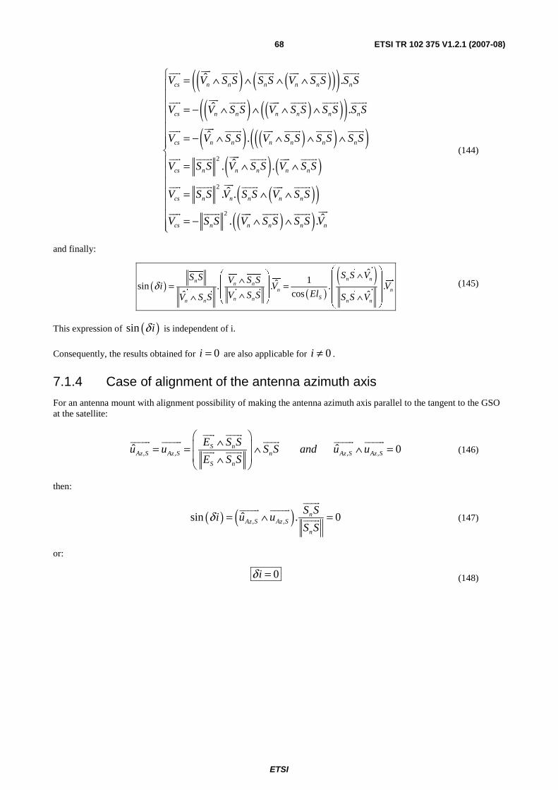
ETSI
ETSI TR 102 375 V1.2.1 (2007-08) 68
( ) ( )( )( )( ) ( )( )( )
( ) ( )( )( )( ) ( )2
ˆ .
ˆ .
ˆ .
ˆ. .
cs n n n n n n
cs n n n n n n
cs n n n n n n
cs n n n n n
V V S S S S V S S S S
V V S S V S S S S S S
V V S S V S S S S S S
V S S V S S V S S
V
= ∧ ∧ ∧ ∧
= − ∧ ∧ ∧ ∧
= − ∧ ∧ ∧ ∧
= ∧ ∧
uur
uur uuur uuur uur uuur uuur
uur
uur uuur uur uuur uuur uuur
uur
uur uuur uur uuur uuur uuur
uur
uur uuur uuur uur uuur
( )( )( )( )
2
2
ˆ. .
ˆ. .
cs n n n n n
cs n n n n n
S S V S S V S S
V S S V S S S S V
⎧⎪⎪⎪⎪⎪⎪⎪⎨⎪⎪⎪
= ∧ ∧⎪⎪⎪ = − ∧ ∧⎪⎩
uur
uur uuur uuur uur uuur
uur
uur uuur uur uuur uuur
(144)
and finally:
( ) ( )( )ˆ
1ˆsin . . . .cosˆ ˆ
n nn n nn n
Sn nn n n n
S S VS S V S Si V V
ElV S SV S S S S Vδ
⎛ ⎞⎛ ⎞ ∧∧ ⎜ ⎟⎜ ⎟= = ⎜ ⎟⎜ ⎟∧∧ ∧⎜ ⎟⎝ ⎠ ⎝ ⎠
uur
uuur
uuur
uur uuur
uur
uur
uur uur uuur uur
uuur uuur
(145)
This expression of ( )sin iδ is independent of i.
Consequently, the results obtained for 0i = are also applicable for 0i ≠ .
7.1.4 Case of alignment of the antenna azimuth axis
For an antenna mount with alignment possibility of making the antenna azimuth axis parallel to the tangent to the GSO at the satellite:
, , , ,ˆ ˆ 0S nAz S Az S n Az S Az S
S n
E S Su u S S and u u
E S S
⎛ ⎞∧⎜ ⎟= = ∧ ∧ =⎜ ⎟∧⎝ ⎠
uur uuur
uuuur uuuur uuur uuuur uuuur
uur uuur (146)
then:
( ) ( ), ,ˆsin . 0nAz S Az S
n
S Si u u
S Sδ = ∧ =
uuur
uuuur uuuur
uuur (147)
or:
0iδ = (148)
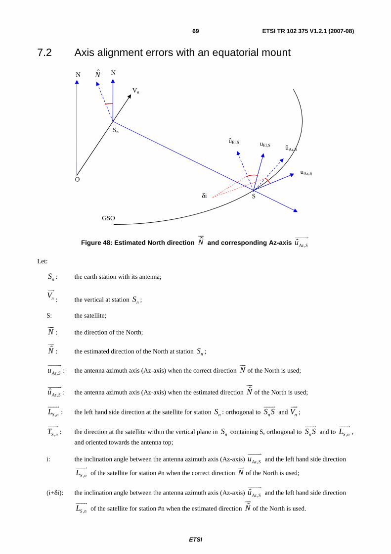
ETSI
ETSI TR 102 375 V1.2.1 (2007-08) 69
7.2 Axis alignment errors with an equatorial mount
N
Vn
O
Sn
S
uAz,S
uEl,S
N
ûAz,S
ûEl,S
δi
GSO
N
Figure 48: Estimated North direction Nuur
and corresponding Az-axis ,ˆAz Suuuuur
Let:
nS : the earth station with its antenna;
nVuur
: the vertical at station nS ;
S: the satellite;
Nuur
: the direction of the North;
Nuur
: the estimated direction of the North at station nS ;
,Az Suuuuur
: the antenna azimuth axis (Az-axis) when the correct direction Nuur
of the North is used;
,ˆAz Suuuuur
: the antenna azimuth axis (Az-axis) when the estimated direction Nuur
of the North is used;
,S nLuuur
: the left hand side direction at the satellite for station nS : orthogonal to nS Suuur
and nVuur
;
,S nTuuur
: the direction at the satellite within the vertical plane in nS containing S, orthogonal to nS Suuur
and to ,S nLuuur
,
and oriented towards the antenna top;
i: the inclination angle between the antenna azimuth axis (Az-axis) ,Az Suuuuur
and the left hand side direction
,S nLuuur
of the satellite for station #n when the correct direction Nuur
of the North is used;
(i+δi): the inclination angle between the antenna azimuth axis (Az-axis) ,ˆAz Suuuuur
and the left hand side direction
,S nLuuur
of the satellite for station #n when the estimated direction Nuur
of the North is used.

ETSI
ETSI TR 102 375 V1.2.1 (2007-08) 70
Then:
,n
Az S
n
N S Su
N S S
∧=∧
uur uuur
uuuur
uur uuur (149)
,
ˆˆ
ˆn
Az S
n
N S Su
N S S
∧=∧
uur
uuur
uuuur
uur
uuur
(150)
( ) ( ), , ,cos . sin .Az S S n S nu i L i T= +uuuur uuur uuur
(151)
( ) ( ), , ,ˆ cos . sin .Az S S n S nu i i L i i Tδ δ= + + +uuuur uuur uuur
(152)
( ), ,ˆ . cosAz S Az Su u iδ=uuuur uuuur
(153)
( ) ( ), , , ,ˆ sin . sin . nAz S Az S S n S n
n
S Su u i T L i
S Sδ δ∧ = ∧ =
uuur
uuuur uuuur uuur uuur
uuur (154)
( ) ( ), ,ˆsin . nAz S Az S
n
S Si u u
S Sδ = ∧
uuur
uuuur uuuur
uuur (155)
( )ˆ
sin .ˆ
n n n
n nn
N S S N S S S Si
N S S S SN S Sδ
⎛ ⎞⎛ ⎞ ⎛ ⎞⎜ ⎟∧ ∧⎜ ⎟ ⎜ ⎟= ∧⎜ ⎟⎜ ⎟ ⎜ ⎟∧∧⎜ ⎟⎜ ⎟ ⎝ ⎠⎝ ⎠⎝ ⎠
uur
uuur uur uuur uuur
uur uur uuur uuur
uuur
(156)
( ) ( )( )( ) ( )( ) ( )( ) ( )
( )( ) ( ) ( )( )2
ˆ .
ˆ ˆ. .
ˆ ˆ. .
ˆ.
n n n
n n n n n n
n n n n n n
n n
N S S N S S S S
S S N S S N S S S S N S S N S S
N S S S S S S N N S S S S S S N
S S N S
∧ ∧ ∧ =
= ∧ ∧ ∧ = ∧ ∧ ∧
⎛ ⎞= ∧ ∧ ∧ = ∧ ∧ ∧⎜ ⎟⎝ ⎠
= − ∧
uur
uuur uur uuur uuur
uur uur
uuur uuur uur uuur uuur uuur uur uuur
uur uur
uuur uuur uuur uur uuur uuur uuur uur
uur
uuur ( ) ( ) ( )( ) ( ) ( )
2 2
2 2 2
ˆ ˆ. . . . .
ˆ ˆ ˆ. . . . . .
n n n n
n n n n n n
S N S S N N S S S S N N S S
S S N N S S S S N N S S S S S S N N
⎧⎪⎪⎪⎪⎨⎪ = − ∧ = − ∧⎪⎪
= ∧ = ∧ = − ∧⎪⎩
uur uur
uuur uur uuur uur uuur uuur uur uuur
uur uur uur
uuur uur uuur uuur uur uuur uuur uuur uur
(157)
( ) ˆsin . .ˆ
n n
nn
S S S S Ni N
S S NS S Nδ
⎛ ⎞∧⎜ ⎟= −⎜ ⎟∧∧ ⎝ ⎠
uuur
uuur uur
uur
uur uuur uur
uuur
(158)
( ) ( )1 ˆsin . .ˆsin ,
n
nn
S S Ni N
S S NN S Sδ
⎛ ⎞∧⎜ ⎟= −⎜ ⎟∧⎝ ⎠
uuur uur
uur
uur uuur uur
uuur
(159)

ETSI
ETSI TR 102 375 V1.2.1 (2007-08) 71
( ) ( )ˆ ˆsin , 1 sin .nn
n
S S NN S S i N
S S Nδ
⎛ ⎞∧⎜ ⎟≈ ⇒ ≈ −⎜ ⎟∧⎝ ⎠
uuur uur
uur uur
uuur
uuur uur (160)
For a given location nS , a given satellite S and for a given inclination error iδ the ends of the vector Nuur
representing
the estimated directions of the North at station nS are on a circle in a plane parallel to the plane ( ),nS S Nuuur uur
and at a
distance equal to ( )sin iδ from nS on a sphere of radius equal to 1.
Sn
S
uAz,S
uEl,S
N
ûAz,S
ûEl,S
δi
GSO
N
sin(δi)
r =1
Figure 49: Circle of ends of vectors Nuur
representing the estimated North directions for a given inclination error iδ
For a given location nS , any satellite S and for a given maximum inclination error iΔ the ends of the vector
Nuur
representing the estimated directions of the North at station nS are within the cone ( )ˆ. cosN N i= Δuur
uur
of axis Nuur
and on a sphere of radius equal to 1 centred in nS .

ETSI
ETSI TR 102 375 V1.2.1 (2007-08) 72
Sn
S
uAz,S
uEl,S
N
ûAz,S
ûEl,S
Δi
GSO
N
sin(Δi)
r =1
Figure 50: Cone of the vectors Nuur
representing the estimated North directions for a given maximum inclination error iΔ
Then the maximum inclination error iΔ is also the maximum angle between the actual direction Nuur
of the North and
the estimated direction Nuur
of the North.
Let:
,N nEl: the elevation of the direction N
uur
of the North pole in station nS;
,N nAz: the azimuth of the direction N
uur
of the North pole in station nS;
( ), ,N n N nEl Elδ+ : the elevation of the estimated direction Nuur
of the North pole in station nS;
( ), ,N n N nAz Azδ+ : the azimuth of the estimated direction Nuur
of the North pole in station nS;
NElΔ : the maximum absolute value of ,N nElδ : ,N n NEl Elδ ≤ Δ ;
NAzΔ : the maximum absolute value of ,N nAzδ : ,N n NAz Azδ ≤ Δ ;
,minnLt : the maximum operational latitude for which the earth station is designed.

ETSI
ETSI TR 102 375 V1.2.1 (2007-08) 73
Then:
( ) ( ) ( )( ) ( )
( ) ( )
, ,
, ,
,
cos cos .cos
0 cos .sin
sin sin
n N n N n
N n N n
n N n
x Lt El Az
N y El Az
z Lt El
⎧ = − = −⎪⎪= = = +⎨⎪
= + = +⎪⎩
uur
(161)
( ) ( )( ) ( )( )
, , , ,
, , , ,
, ,
cos .cos
ˆ cos .sin
sin
N n N n N n N n
N n N n N n N n
N n N n
x El El Az Az
N y El El Az Az
z El El
δ δ
δ δ
δ
⎧ = − + +⎪⎪= = + + +⎨⎪
= + +⎪⎩
uur
(162)
and consequently:
,
, 0N n n
N n
El Lt
Az
=⎧⎪⎨ =⎪⎩ (163)
( ) ( )2 2
, ,,
ˆ. 1 2.sin 2.sin .cos .cos2 2
N n N nn n N n
El AzN N Lt Lt El
δ δδ⎛ ⎞ ⎛ ⎞= − − +⎜ ⎟ ⎜ ⎟
⎝ ⎠ ⎝ ⎠
uur
uur
(164)
The following condition:
( )2
ˆ. cos 1 2.sin2
iN N i
Δ⎛ ⎞≥ Δ = − ⎜ ⎟⎝ ⎠
uur
uur
(165)
becomes:
( ) ( )2 2 2
, ,,sin sin .cos .cos sin
2 2 2N n N n
n n N n
El Az iLt Lt El
δ δδ⎛ ⎞ ⎛ ⎞ Δ⎛ ⎞+ + ≤ ⎜ ⎟⎜ ⎟ ⎜ ⎟
⎝ ⎠⎝ ⎠ ⎝ ⎠ (166)
If NAzΔ and NElΔ
are the maximum absolute values of ,N nAzδ and ,N nElδ
, and if ,minnLt is the maximum
operational latitude for which the earth station is designed, then:
( ) ( )2 2 2
, ,,min ,min ,sin sin .cos .cos sin
2 2 2N n N n
n n N n
El Az iLt Lt El
Δ Δ⎛ ⎞ ⎛ ⎞ Δ⎛ ⎞+ + Δ ≤ ⎜ ⎟⎜ ⎟ ⎜ ⎟⎝ ⎠⎝ ⎠ ⎝ ⎠
(167)
When the latitude of the station is known with an accuracy highly better than iΔ , e.g. with a GPS, then the maximum error in azimuth of the direction of the local North or South is given by the following relationship:
( )
,,
sin2
0 sin2 cos
N n
N nn
i
AzEl
Lt
⎛ Δ ⎞⎜ ⎟⎛ ⎞Δ ⎝ ⎠Δ = ⇒ ≤⎜ ⎟
⎜ ⎟⎝ ⎠ (168)
NOTE: A North-South error of 1 km on the location of the earth station corresponds to an error of 0,009° (= 360° x 1 km / 40 000 km) on the latitude of the earth station. This error is considered negligible for the antenna axis alignment. A GPS gives a better accuracy.

ETSI
ETSI TR 102 375 V1.2.1 (2007-08) 74
For antennas designed to operate at any latitude the condition becomes the following:
[ ],
,
0
80 , 80
N n
N n
n
ElAz i
Lt
Δ =⎧ ⎫⎪ ⎪⇒ Δ ≤ Δ⎨ ⎬∈ − ° + °⎪ ⎪⎩ ⎭
(169)
8 Contour computation method
8.1 General The computation of the contour of the shadows of the visible part of the GSO on an antenna radiation pattern is required for the following three cases:
a) the case of a station in a given location pointed towards a given satellite;
b) the case of stations within a range of latitudes pointed towards any satellites on the GSO and above a given elevation, including the case of a station in a given location pointed towards any satellites on the GSO and above a given elevation.
The functions referred to within the present clause 8 are described in detail in clause 9 (Excel tool).
The method of the computation of the contour is based on the type of antenna mount considered within the present document. For any other type of antenna mount the same methodology should be followed for the determination of the normal inclination of the antenna Az-axis and for the determination of the impact of the antenna mount axes alignment errors on the antenna Az-axis inclination and the methods described within the following two clauses 8.2 and 8.3 apply.
8.2 Case of 1 ES and 1 satellite In the case of a station in a given location pointed towards a given satellite, for the determination of the shadow of the GSO and its vicinity on the antenna radiation pattern, within the (α, ϕ) domain, the method described in clause 9.7.2 applies.
The GSO shadow of the GSO and its vicinity should be computed:
a) for no alignment error;
b) for the maximum positive alignment error;
c) for the maximum negative alignment error; and
d) if necessary when the maximum alignment error is large for intermediate alignment errors.
These computations should be repeated for:
e) for the maximum inclination offset i of the antenna Az-axis;
f) for the minimum inclination offset i of the antenna Az-axis; and
g) if necessary when the range of inclination offset is large for intermediate values.
For antennas which could be used up-side down, all the above computations should be repeated for the inclination offset increased or decreased by 180°.
The contour of the shadows of the GSO and its vicinity, with alignment errors and inclination offsets, on the antenna radiation pattern, within the (α, ϕ) domain, is the envelop of all the shadows which have been computed.
ETSI
ETSI TR 102 375 V1.2.1 (2007-08) 75
8.3 Case of ESs and satellites In the case of stations within a range of latitudes pointed towards any satellites on the GSO and above a given elevation, including the case of a station in a given location pointed towards any satellites on the GSO and above a given elevation, for the determination of the contour of the shadows of the GSO and its vicinity on the antenna radiation patterns, within the (α, ϕ) domain, the method described in clause 9.6.13 applies.
The contour of the shadows of the GSO and its vicinity should be computed:
a) for no alignment error;
b) for the maximum positive alignment error;
c) for the maximum negative alignment error; and
d) if necessary when the maximum alignment error is large for intermediate alignment errors.
These computations should be repeated:
e) for the maximum inclination offset i of the antenna Az-axis;
f) for the minimum inclination offset i of the antenna Az-axis; and
g) if necessary when the range of inclination offset is large for intermediate values.
For antennas which could be used upside down, all the above computations should be repeated for the inclination offset increased or decreased by 180°.
The contour of the shadows of the GSO and its vicinity, with alignment errors and inclination offsets, on the antenna radiation patterns, within the (α, ϕ) domain, is the envelop of all the contours which have been computed.
9 Excel tool
9.1 General It is recognized that all the problems of limits and discontinuities have not been fully considered, mainly when crossing the equator or in the vicinity of the sub-satellite point on the Earth. However it is considered that this tool provide enough information on the limit within the (α, ϕ) domain of the shadow of the GSO arc and its vicinity for measurement purpose.
The tool consists of:
• a worksheet, named "GSO";
• 2 Visual Basic Modules, named: "Basic_functions" and "GSO_arc_functions".
The "GSO" worksheet contains:
• 3 sections for: the constants, the input data, the GSO shadow output data, the contour output data;
• 4 graphs:
- the GSO arc and its vicinity for an observer at the ES (the elevation vs. azimuth of the GSO points);
- the GSO arc and its vicinity for the antenna (Phi_El vs. Phi_Az of the GSO points);
- the GSO arc and its vicinity within the (α, ϕ) domain and the limit within the (α, ϕ) domain of the shadow of the GSO arc and its vicinity (Phi.sin(Alpha) vs. Phi.cos(Alpha) of the GSO points);
- the minimum off-axis angle, corresponding to the minimum satellite longitude offset, within the (α, ϕ) domain.

ETSI
ETSI TR 102 375 V1.2.1 (2007-08) 76
9.2 Cell colours Mainly 4 colours are used for the cells of the worksheet:
Table 4: Colours of cells in tables
Brown for constants Blank for input data Blue for formulas or results from a Visual Basic subroutine Green for titles
9.3 Constants Presently the worksheet contains only one constant:
Table 5: Constants declared within Excel worksheets
Constants Remark Antenna type table 1: Az-El mount without alignment 2: Az-El mount WITH ideal alignment 3: Az-El mount WITH polar alignment 4: Equatorial mount
This table is use to display the type of antenna selected by a number.
Other constants are declared:
Table 6: Global constants associated to Excel worksheets
Name Value Unit Remark Pi_ = 3,14159265358979 dg = Pi_/180 rad/° p_ = 42 164 km GSO radius R_ = 6 371 km Earth radius Sqr_2 = 1,4142135623731 2=
9.4 Buttons Two types of buttons are used within the worksheet:
• one "Command button" with caption "Contour" which initiate the computation of the contour with the input parameters;
• several "Spin buttons" ( � � ) used to increment or decrement values of some input parameters, e.g.:
Table 7: Examples of Excel sheet rows with spin buttons
Title Real variable Integer variable Spin button ES latitude max 74,000°/N 74°/N � � ES latitude min -74,000°/N 65 462°/N � �
When the spin button value of a row is incremented or decremented, the associated integer variable within the row (e.g. i_ES_Lt_min) and the real variable (e.g. ES_Lt_min) of the row are updated with the spin button integer value. Any modification of the integer variable results in a modification of the spin button value with that value. A negative (e.g. -74°) value may be given to an integer variable but after action on the spin button the number displayed will be equal to -74 + 216.
There is an exception for "Lg_S0" where the integer variable is an integer between -100 and 100 and representing a percentage of the maximum longitude offset of the other satellite.

ETSI
ETSI TR 102 375 V1.2.1 (2007-08) 77
Table 8: Case of row with spin button for "Lg_S0"
Title Real variable Integer variable Spin button Lg_S0 70,553°/E 100 � �
9.5 Input data
Table 9: Input data within worksheet "GSO"
Excel worksheet input data area Remarks Inputs Antenna mount Type of antenna mount 2 2: Az-El mount WITH
ideal alignment Type of antenna: 1: Az-El mount without alignment 2: Az-El mount WITH alignment 3: Az-El mount WITH polar. alignment 4: equatorial mount
Permanent alignment error 0,000°/N 0 � � ∈[-90°, +90°] The sign of this offset is given to the inclination error
Az-El antenna mount Vertical direction offset 0,000° Recommended values ∈[-180°, +180°]
The sign of this offset is given to the inclination error
Equatorial antenna mount North pole direction azimuth offset
4,000° Recommended values ∈ [-0°, +360°]
North pole direction elevation offset
3,000° Recommended values ∈ [-90°, +90°] The sign of this offset is given to the inclination error
E/H field alignment Tilt angle with the North pole direction of the electric field at the satellite
22,000° Recommended values ∈ [-180°, +180°]
Longitude of the centre of the satellite beam coverage
5,000°/E Recommended values ∈ [-180°, +180°]
Latitude of the centre of the satellite beam coverage
50,000°/E Recommended values ∈ [-90°, +90°]
H_polar TRUE TRUE for alignment on the received H field FALSE for alignment on the received E field
E/H field alignment error 0,000° Recommended values ∈ [-180°, +180°] The sign of this offset is given to the inclination error
Antenna inclination i_Az -127,930° Inclination with Az-El mount i_Eq 52,700° Inclination with equatorial mount I_E 74,724° Inclination with E or H field alignment i_0 -127,930° The selected antenna inclination according to the
antenna type Alignment errors Alignment error due to Az-El mount
0,000° Computed with the axes alignment error
Alignment error due to Az-El mount with E field
0,000° No formula available
Alignment error due to equatorial mount
4,654° Computed with the axes alignment error
Alignment error 0,000° Selected alignment error according to the antenna mount type
Earth station ES latitude 36,000°/N 36°/N � � ∈[-90°, +90°] ES longitude 0,000°/E 0°/E � � ∈[-180°, +180°] Minimum ES elevation 7,000° 7° � � ∈[-90°, +90°], of the pointed satellite Minimum horizon elevation 0,000° 0° � � ∈ [-90°, +90°], of the other satellite Max longitude offset 70,553° Function of the minimum ES elevation

ETSI
ETSI TR 102 375 V1.2.1 (2007-08) 78
Excel worksheet input data area Remarks Pointed satellite Lg_S0 70,553°/E 100 � � = longitude of the ES + percentage of the
maximum longitude offset, with percentage ∈[-100, +100]
Azimuth_0 101,724° Azimuth of the pointed satellite Elevation_0 7,000° Elevation of the pointed satellite Range of ES latitudes ES latitude min -74,000°/N 65 462°/N � � ES latitude max 74,000°/N 74°/N � � ES latitude step 1,480°/N Latitude step for the computations Markers Phi 173,000° 173° � � Marker Phi = constant Alpha 0,000° 0° � � Marker Alpha = constant
The minimum horizon elevation could be negative for an ES high above the sea level:
Table 10: Examples of negative horizon elevations for various ES altitudes above the sea level
ES altitude Horizon elevation 0 m -0,000°
100 m -0,321° 200 m -0,454° 500 m -0,718°
1 000 m -1,015° 1 500 m -1,243° 2 000 m -1,435° 3 000 m -1,758° 4 000 m -2,030°
9.6 Functions and Subroutines The following Visual Basic functions and subroutines of the module "GSO_arc_functions" are used.
9.6.1 Function Azimuth()
The function Azimuth gives the satellite azimuth [°/N].
The inputs of the function Phi_ Azimuth(Lg_S, Lt_S, Lg_n, Lt_n) are:
• Lg_S the satellite longitude [°/E];
• Lt_S the satellite latitude [°/N];
• Lg_n the ES longitude [°/E];
• Lt_n the ES latitude [°/N].
The value of the function Azimuth is computed with the following equation:
( )( ) ( ) ( )( ) ( )
sin .cos2 sin ,
tan .cos
n S n
n S n
S n
Lt Lg LgAz ArcTan Lg Lg
Lt Lt
⎛ ⎞− −⎛ ⎞= ⎜ − ⎟⎜ ⎟⎜ ⎟⎜ ⎟+⎝ ⎠⎝ ⎠ (170)

ETSI
ETSI TR 102 375 V1.2.1 (2007-08) 79
9.6.2 Function Elevation()
The function Elevation gives the satellite elevation [°/E].
The inputs of the function Phi_ Elevation(Lg_S, Lt_S, Lg_n, Lt_n) are:
• Lg_S the satellite longitude [°/E];
• Lt_S the satellite latitude [°/N];
• Lg_n the ES longitude [°/E];
• Lt_n the ES latitude [°/N].
The value of the function Elevation is computed with the following equations:
( ) ( ) ( ) ( ) ( ) ( ).
cos cos .cos .cos sin .sin.
nn S n S n S n
S SLt Lt Lg Lg Lt Lt
Rθ
ρ= = − +
r r
(171)
( ) ( )( )2 2
.cos.sin
2. . .cos
nn nn
n n
RS S VEl
S S R R
ρ θρ ρ θ
−= =
+ −
uuur r
uuur
(172)
9.6.3 Function Phi_Az()
Phi_Az is the angle [°] of the projection of the considered direction within the plane defined by the antenna main beam axis and its Az-axis, with the antenna main beam axis.
The inputs of the function Phi_ Az (Az_S0, El_S0, i, Az_S, El_S) are:
• Az_S0 the pointed satellite azimuth [°/E];
• El_S0 the pointed satellite elevation [°];
• Az_S the other satellite azimuth [°/E];
• El_S the other satellite elevation [°];
• i the inclination of the antenna Az-axis [°].
The value of the function Phi_ Az is computed with the following equations:
( ) ( ) ( )( ) ( ) ( )( ) ( ) ( ) ( )
0
0 0
0 0
,
sin .sin .cos
. cos .cos .sin
sin .cos .sin .cos
S S
a n Az S S S S
S S S S
i El El
x S S u i El Az Az
i El El Az Az
⎛ ⎞+⎜ ⎟⎜ ⎟= = + −⎜ ⎟⎜ ⎟− −⎝ ⎠
uuur uuuuur
(173)
( ) ( ) ( ) ( ) ( )0 0 0 0,. cos .cos .cos sin .sina n R S S S S S S Sz S S u El El Az Az El El= = − +
uuur uuuur
(174)
( )2 ,Az a aArcTan x zϕ =
(175)

ETSI
ETSI TR 102 375 V1.2.1 (2007-08) 80
9.6.4 Function Phi_El()
Phi_El is the angle [°] of the projection of the considered direction within the plane defined by the antenna main beam axis and its El-axis, with the antenna main beam axis.
The inputs of the function Phi_ Az (Az_S0, El_S0, i, Az_S, El_S) are:
• Az_S0 the pointed satellite azimuth [°/E];
• El_S0 the pointed satellite elevation [°];
• Az_S the other satellite azimuth [°/E];
• El_S the other satellite elevation [°];
• i the inclination of the antenna Az-axis [°].
The value of the function Phi_ El is computed with the following equations:
( ) ( ) ( )( ) ( ) ( ) ( )( ) ( ) ( )
0
0 0 0
0
,
sin .cos .sin
. cos .sin .cos .cos
cos .cos .sin
S S S
a n El S S S S S
S S
i El Az Az
y S S u i El El Az Az
i El El
⎛ ⎞− −⎜ ⎟⎜ ⎟= = − −⎜ ⎟⎜ ⎟+⎝ ⎠
uuur uuuuur
(176)
( )El aArcSin yϕ =
(177)
9.6.5 Functions Phi_cos_Alpha() and Phi_sin_Alpha()
The outputs of these functions are such that:
• Phi_cos_Alpha = Phi * Cos(alpha);
• Phi_sin_Alpha = Phi * sin(alpha).
where:
• Phi: is the off-axis angle [°] of the considered direction measured from the antenna main beam axis;
• Alpha: is the angle [°] between:
- the plane defined by the antenna main beam axis and the considered direction; and
- the plane defined by the antenna main beam axis and its Az-axis.
The inputs of these functions Phi_cos_Alpha(Phi_Az, Phi_El) and Phi_sin_Alpha(Phi_Az, Phi_El) are:
• Phi_Az: the angle [°] of the projection of the considered direction within the plane defined by the antenna main beam axis and its Az-axis, with the antenna main beam axis;
• Phi_El: the angle [°] of the projection of the considered direction within the plane defined by the antenna main beam axis and its El-axis, with the antenna main beam axis.
The value of the function Phi_cos_Alpha is computed with the following equations:
( ) ( ) ( )( ), cos .cosM a M El AzArcCos z ArcCosϕ ϕ ϕ= =
(178)
( ) ( ) ( )( )2 sin ,cos .sinM El El AzArcTanα ϕ ϕ ϕ=
(179)
( )Phi_cos_Alpha= .cosM Mϕ α
(180)

ETSI
ETSI TR 102 375 V1.2.1 (2007-08) 81
( )Phi_sin_Alpha= .sinM Mϕ α (181)
9.6.6 Function Inclination_with_Az_El_mount()
The function Inclination_with_Az_El_mount returns the value of the inclination of the antenna Az-axis so that it is aligned with the GSO tangent.
The inputs of the function Az_El_mount(Lg_S, Lt_S, Lg_n, Lt_n) are:
• Lg_S: the pointed satellite longitude [°/E];
• Lt_S: the pointed satellite latitude [°/N];
• Lg_n: the ES longitude [°/E];
• Lt_n: the ES latitude [°/N].
The value of the function Az_El_mount is computed with the set of equations selected in clause 6.9.
9.6.7 Function Inclination_with_E_field_alignment()
Inclination_with_E_field_alignment(Lg_S, Lt_S, Lg_c, Lt_c, i_E0, Lg_n, Lt_n, H_polar).
The function Inclination_with_E_field_alignment returns the value of the inclination of the antenna Az-axis so that it is aligned with the E or H field received from the satellite.
The inputs of the function E_field_alignment(Lg_S, Lt_S, Lg_c, Lt_c, i_E0, Lg_n, Lt_n, H_polar) are:
• Lg_S: the pointed satellite longitude [°/E];
• Lt_S: the pointed satellite latitude [°/N];
• Lg_c: the centre of coverage longitude [°/E];
• Lt_c: the centre of coverage latitude [°/N];
• i_E0: the radiated E field tilt angle [°/N];
• Lg_n: the ES longitude [°/E];
• Lt_n: the ES latitude [°/N];
• H_polar: TRUE when the horizontal polar is used, FALSE when the vertical polar is used.
The value of the function Inclination_with_E_field_alignment is computed with the set of equations selected in clause 6.10.
9.6.8 Function Inclination_with_equatorial_mount()
The function Inclination_with_equatorial_mount returns the value of the inclination of the antenna Az-axis when a perfect equatorial mount is used.
The inputs of the function Inclination_with_equatorial_mount(Lg_S, Lt_S, Lg_n, Lt_n) are:
• Lg_S: the pointed satellite longitude [°/E];
• Lt_S: the pointed satellite latitude [°/N];
• Lg_n: the ES longitude [°/E];
• Lt_n: the ES latitude [°/N].

ETSI
ETSI TR 102 375 V1.2.1 (2007-08) 82
The value of the function Inclination_with_equatorial_mount is computed with the set of equations selected in clause 6.11.
9.6.9 Function Az_El_mount_alignment_error()
The function returns the maximum value maxiδ of the offset iδ of the antenna azimuth axis ,Az Suuuuur
due to a maximum
vertical axis offset maxθ , for a antenna with an azimuth-elevation mount.
The inputs of the function Az_El_mount_alignment_error(Vertical_offset, El_S) are:
• Vertical_offset: the maximum vertical axis offset maxθ [°];
• El_S: the elevation of the pointed satellite [°].
The value of the function Az_El_mount_alignment_error is computed with the following equation:
( )( )
max
max max
max max
ˆsinˆ
2 cos
ˆ2 2
S
S
S
For El i ArcSinEl
For El i rad
θπ θ δ
π πθ δ
⎧ ⎛ ⎞⎪ ⎜ ⎟≤ − =⎪ ⎜ ⎟⎪ ⎜ ⎟⎨ ⎝ ⎠⎪⎪ − ≤ =⎪⎩ (182)
The sign of the Vertical_offset is given to the inclination offset maxiδ :
( )max max maxˆ: .i Sign iδ θ δ= (183)
9.6.10 Function Az_El_mount_with_E_field_alignment_error()
The function returns the value of the offset iδ of the antenna azimuth axis ,Az Suuuuur
due to the E or H field alignment
error, for an antenna with an azimuth-elevation mount and with polarization alignment.
The input of the function Az_El_mount_with_E_field_alignment_error (di_E) is:
• di_E: the polarization alignment error [°].
The value of the function Az_El_mount_with_E_field_alignment_error is computed with the following equation:
Ei iδ δ= (184)
The sign of the di_E is given to the inclination offset iδ :
( ): .Ei Sign i iδ δ δ= (185)
NOTE: It is recognized that presently the above equations could be simplified (e.g. Ei iδ δ= ) but the general
structure of this clause is kept identical to other similar clauses for possible future developments of this clause for taking into consideration the various sources of errors.
ETSI
ETSI TR 102 375 V1.2.1 (2007-08) 83
9.6.11 Function Equatorial_mount_alignment_error()
The function returns the variation value ( iΔ ) of the antenna Az-axis inclination due to errors on the equatorial mount North-South axis.
The inputs of the function Equatorial_mount_alignment_error(dAz_N, dEl_N, Lt_n) are:
• dAz_N: the North pole direction azimuth offset [°];
• dEl_N: the North pole direction elevation offset [°];
• Lt_n: the ES latitude [°/N].
The value of the function Equatorial_mount_alignment_error is computed with the following equation:
( ) ( )2 2
2. sin sin .cos .cos2 2
N Nn n N
El Azi ArcSin Lt Lt El
δ δ δ⎛ ⎞⎛ ⎞ ⎛ ⎞⎜ ⎟Δ = + +⎜ ⎟ ⎜ ⎟⎜ ⎟⎝ ⎠ ⎝ ⎠⎝ ⎠
(186)
The sign of the dEl_N is given to the inclination offset iΔ :
( ): .Ni Sign El iδΔ = Δ (187)
9.6.12 Function Max_satellite_longitude_offset()
The function returns the maximum longitude offset ( )S nLg Lg− of a satellite visible at a given minimum elevation.
The inputs of the function Max_satellite_longitude_offset(Lt_n, El_min, Lt_S) are:
• Lt_n: the ES latitude [°/N];
• El_min: the minimum elevation of the satellite [°]. This parameter is optional. The default value is equal to 0°;
• Lt_S: the satellite latitude [°/N]. This parameter is optional. The default value is equal to 0°.
The value of the function Max_satellite_longitude_offset is computed with the following equations:
( ) ( ) ( ) ( )2
2 2cos .cos sin . 1 .cosn n n n
R REl El Elθ
ρ ρ⎛ ⎞ ⎛ ⎞= + −⎜ ⎟ ⎜ ⎟⎝ ⎠ ⎝ ⎠
(188)
( ) ( ) ( ) ( )( ) ( )
cos sin .sin
cos .cosn S n
S nS n
Lt LtLg Lg ArcCos
Lt Lt
θ⎛ ⎞−− = ⎜ ⎟⎜ ⎟
⎝ ⎠ (189)
9.6.13 Subroutine GSO_external_contour()
The subroutine GSO_external_contour() computes the contour within the (α, ϕ) domain of the shadows of the GSO arc and its vicinity for various positions of the ES and the pointed satellite.
This subroutine is activated by the command button "Contour" and by some spin buttons.
The inputs of the subroutine GSO_external_contour() are read in the worksheet "GSO":
• ES_Lg: the earth station longitude [°];
• ES_Lt_min: the earth station minimum latitude [°];
• ES_Lt_max: the earth station maximum latitude [°];
ETSI
ETSI TR 102 375 V1.2.1 (2007-08) 84
• ES_El_min: the minimum elevation of the pointed satellite [°];
• Hz_El_min: the minimum elevation of the satellite to be protected [°];
• Type_of_antenna_mount: 1 for Az_El_mount_without_alignment; 2 for Az_El_mount_WITH_alignment; 3 for Az_El_mount_WITH_polar_alignment; 4 for Equatorial_mount;
• Permanent_alignment_error: the permanent inclination offset of the antenna Az-axis [°];
• Vertical_offset: the maximum error of the vertical [°] of an Az-El mount;
• dAz_N: the error in azimuth of the pole axis of an equatorial mount [°];
• dEl_N: the error in elevation of the pole axis of an equatorial mount [°].
The contour is computed for three adjacent satellite latitudes (-3°, 0° and +3°), and for different cases:
• the cases where the ES latitude varies from the minimum latitude to the maximum latitude, the ES antenna is successively pointed towards the western and eastern satellites at the minimum elevation, and the satellites to be protected are successively the eastern and western satellites at the minimum elevation;
• the cases where the ES latitude is maximum, the ES antenna is successively pointed towards the western and eastern satellites at the minimum elevation, and the longitude of the satellite to be protected varies from the eastern to the western satellite longitudes at the minimum elevation. If the absolute value of the ES maximum latitude is lower than 1° then computations are made with 1° instead of the ES maximum latitude;
• the cases where the ES latitude is minimum, the ES antenna is successively pointed towards the western and eastern satellites at the minimum elevation , and the longitude of the satellite to be protected varies from the eastern to the western satellite longitudes at the minimum elevation. If the absolute value of the ES minimum latitude is lower than 1° then computations are made with 1° instead of the ES minimum latitude;
• the cases where the ES latitude is minimum, the longitude of the satellite pointed by the ES antenna varies from the eastern to the western satellite longitudes at the minimum elevation, and the longitude of the satellite to be protected is successively the eastern to the western satellite longitudes at the minimum elevation. If the absolute value of the ES minimum latitude is lower than 1° then computations are made with 1° instead of the ES minimum latitude.
In each case, for a given pointed satellite longitude (Lg_S0) and a given longitude (Lg_S) of the other satellite the values of the following variables are computed using the functions already described:
Table 11: Intermediates variables of subroutine GSO external contour
Variables Equations Remarks Az_S0 = Azimuth (Lg_S0, 0, ES_Lg, ES_Lt) '°/N Azimuth of the pointed satellite El_S0 = Elevation (Lg_S0, 0, ES_Lg, ES_Lt) '° Elevation of the pointed satellite Az_S = Azimuth (Lg_S, Lt_S, ES_Lg, ES_Lt) '°/N Azimuth of the other satellite El_S = Elevation (Lg_S, Lt_S, ES_Lg, ES_Lt) '° Elevation of the other satellite Nominal_inclination = (See next table) Antenna Az-axis inclination,
according to the Type_of_antenna_mount Alignment_error = (See next table) Antenna Az-axis inclination error due to the
antenna mount axes alignment errors, According to the Type_of_antenna_mount
i_S0 = Nominal_inclination + Alignment_error Permanent_alignment_error
Global inclination of the antenna Az-axis
Phi_Az_S = Phi_Az (Az_S0, El_S0, i_S0, Az_S, El_S) '° Off-axis angle along the antenna Az-Axis Phi_El_S = Phi_El (Az_S0, El_S0, i_S0, Az_S, El_S) '° Off-axis angle along the antenna El-Axis Phi_cos_Alpha_S = Phi_cos_Alpha (Phi_Az_S, Phi_El_S) Phi * Cos(Alpha) '° Alpha is defined after the
next table Phi_sin_Alpha_S = Phi_sin_Alpha (Phi_Az_S, Phi_El_S) Phi * Sin(Alpha) '° Alpha is defined after the
next table

ETSI
ETSI TR 102 375 V1.2.1 (2007-08) 85
Table 12: Alignment error and nominal inclination intermediates variables of subroutine GSO external contour
Type_of_antenna_mount Alignment_error Nominal_inclination Az_El_mount_without_alignment Az_El_mount_alignment_error
(Vertical_offset, El_S0) 0
Az_El_mount_WITH_alignment 0 Inclination_with_Az_El_mount (Lg_S0, 0, ES_Lg, ES_Lt)
Az_El_mount_WITH_polar_alignment 0 Inclination_with_E_field_alignment (Lg_S0, 0, Lg_c, Lt_c, i_E0, ES_Lg, ES_Lt, H_polar)
Equatorial_mount Equatorial_mount_alignment_error (dAz_N, dEl_N, ES_Lt)
Inclination_with_equatorial_mount (Lg_S0, 0, ES_Lg, ES_Lt)
The outputs are stored in the table "GSO_external_contour" of the worksheet "GSO". The outputs are:
• Phi_cos_Alpha_S = Phi * Cos(alpha) '°; and
• Phi_sin_Alpha_S = Phi * Sin(alpha) '°.
where:
• Phi: is the off-axis angle [°] of each considered direction measured from the antenna main beam axis;
• Alpha: is the angle [°] between:
- the plane defined by the antenna main beam axis and each considered direction; and
- the plane defined by the antenna main beam axis and its Az-axis.
9.6.14 Subroutine GSO_internal_contour()
The subroutine GSO_internal_contour () computes the minimum off-axis angles within the (α, ϕ) domain corresponding to the minimum longitude offset (dLg_S_min) for various positions of the ES and the pointed satellite.
This subroutine as the subroutine GSO_internal_contour() is activated by the command button "Contour" and by some spin buttons.
The inputs of the subroutine GSO_internal_contour() are read in the worksheet "GSO". Their are those of the subroutine GSO_external_contour() plus the following input data:
• dLg_S_min: the minimum longitude offset [°].
The minimum off-axis angles corresponding to the minimum longitude offset (dLg_S_min) have been computed for three adjacent satellite latitudes (-3°, 0° and +3°), and for following cases:
• the cases where the ES latitude varies from the minimum latitude to the maximum latitude, the ES antenna is pointed towards the satellite at the ES latitude, and the satellites to be protected are successively the East and West satellites at the minimum longitude offset (dLg_S_min);
• the cases where the ES latitude varies from the minimum latitude to the maximum latitude, the ES antenna is successively pointed towards the West and East satellites at the minimum elevation, and the satellites to be protected are successively the East and West satellites at the minimum longitude offset (dLg_S_min).
The outputs are stored in the table "GSO_internal_contour" of the worksheet "GSO". The structure of that table is identical to the structure of the "GSO_external_contour" table.

ETSI
ETSI TR 102 375 V1.2.1 (2007-08) 86
9.7 Output data and graphs
9.7.1 General
The outputs of the worksheet "GSO" consist in:
• the GSO shadow for a given ES and a given pointed satellite;
• the GSO_external_contour (See the subroutine GSO_external_contour());
• the GSO_internal_contour (See the subroutine GSO_ internal _contour());
• 4 graphs which have already been presented along the present document.
9.7.2 GSO shadow for a given ES and a given pointed satellite
The GSO shadow on the antenna radiation pattern, within the (α, ϕ) domain for a given ES and a given pointed satellite uses the following inputs.
Table 13: Inputs for the computation of the GSO shadow on the antenna radiation pattern
Title Variable Remarks Antenna inclination i_0 -127,930° the selected antenna inclination according to the antenna type. Earth station ES latitude ES_Lt 36,000°/N ∈ [-90°, +90°] ES longitude ES_Lg 0,000°/E ∈ [-180°, +180°] Minimum horizon elevation
Hz_El_min
0,000° ∈ [-90°, +90°], of the other satellite
Pointed satellite Azimuth_0 Azimuth_0 101,724 azimuth of the pointed satellite Elevation_0 Elevation_0 7,000 elevation of the pointed satellite

ETSI
ETSI TR 102 375 V1.2.1 (2007-08) 87
The GSO shadow on the antenna radiation pattern is computed within the worksheet "GSO" according to the following formulae.
Table 14: Formulae and intermediate variables for the computation of the GSO shadow on the antenna readiation pattern
Title Variable Formula Remarks Satellite latitude Lt_S -3 Satellite latitude: -3, 0 and +3
successively Max satellite longitude offset
dLg_S_max = Max_satellite_longitude_offset (ES_Lt; Hz_El_min; Lt_S)
Satellite longitude step
dLg_S = dLg_S_max / 50
Satellite longitude Lg_S = Lg_S + dLg_S Satellite longitude Lg_S is initiated with: (ES_Lg - dLg_S_max) and is increased up to: (ES_Lg + dLg_S_max)
Az_S - 180° Az_S_180 = Azimuth (Lg_S; Lt_S; ES_Lg; ES_Lt) - 180
Satellite azimuth
El_S El_S = Elevation (Lg_S; Lt_S; ES_Lg; ES_Lt)
Satellite elevation
Phi_Az Phi_Az = Phi_Az (Azimuth_0; Elevation_0; i_0; Az_S_180 + 180; Lt_S)
The angle [°] of the projection of the satellite direction within the plane defined by the antenna main beam axis and its Az-axis, with the antenna main beam axis
Phi_El Phi_El = Phi_El (Azimuth_0; Elevation_0; i_0; Az_S_180 + 180; El_S)
The angle [°] of the projection of the satellite direction within the plane defined by the antenna main beam axis and its El-axis, with the antenna main beam axis
ϕ.cos (α) Phi_cos_Alpha_S = Phi_cos_Alpha (Phi_Az; Phi_El) For the meaning of Phi_cos_Alpha_S see the subroutine "GSO_external_contour".
ϕ.sin (α) Phi_sin_Alpha_S = Phi_sin_Alpha (Phi_Az; Phi_El) For the meaning of Phi_sin_Alpha_S see the subroutine "GSO_external_contour".

ETSI
ETSI TR 102 375 V1.2.1 (2007-08) 88
History
Document history
V1.1.1 February 2005 Publication
V1.2.1 August 2007 Publication


![TS 103 246-4 - V1.2.1 - Satellite Earth Stations and ... · Modal verbs terminology ... (Verbal forms for the expression of ... OMA-TS-LPPe-V2.0: "LPP Extensions Specification". [6]](https://img.dokumen.tips/doc/110x75/5ad268df7f8b9afa798cadd1/ts-103-246-4-v121-satellite-earth-stations-and-verbs-terminology-verbal.jpg)