Embed Size (px)
Citation preview

ETSI TR 102 193 V1.1.1 (2003-04)
Technical Report
Fixed Radio Systems;Point-to-point and Point-to-multipoint equipments;
Aspects regarding P-P and P-MPdigital radio equipment with ATM and IP interfaces
carrying native ATM or IP over ATM payloads

ETSI
ETSI TR 102 193 V1.1.1 (2003-04) 2
Reference DTR/TM-04112
Keywords ATM, interface, IP multipoint, point-to-point, radio
ETSI
650 Route des Lucioles F-06921 Sophia Antipolis Cedex - FRANCE
Tel.: +33 4 92 94 42 00 Fax: +33 4 93 65 47 16
Siret N° 348 623 562 00017 - NAF 742 C
Association à but non lucratif enregistrée à la Sous-Préfecture de Grasse (06) N° 7803/88
Important notice
Individual copies of the present document can be downloaded from: http://www.etsi.org
The present document may be made available in more than one electronic version or in print. In any case of existing or perceived difference in contents between such versions, the reference version is the Portable Document Format (PDF).
In case of dispute, the reference shall be the printing on ETSI printers of the PDF version kept on a specific network drive within ETSI Secretariat.
Users of the present document should be aware that the document may be subject to revision or change of status. Information on the current status of this and other ETSI documents is available at
http://portal.etsi.org/tb/status/status.asp
If you find errors in the present document, send your comment to: [email protected]
Copyright Notification
No part may be reproduced except as authorized by written permission. The copyright and the foregoing restriction extend to reproduction in all media.
© European Telecommunications Standards Institute 2003.
All rights reserved.
DECTTM, PLUGTESTSTM and UMTSTM are Trade Marks of ETSI registered for the benefit of its Members. TIPHONTM and the TIPHON logo are Trade Marks currently being registered by ETSI for the benefit of its Members. 3GPPTM is a Trade Mark of ETSI registered for the benefit of its Members and of the 3GPP Organizational Partners.
ETSI
ETSI TR 102 193 V1.1.1 (2003-04) 3
Contents
Intellectual Property Rights ................................................................................................................................4
Foreword.............................................................................................................................................................4
Introduction ........................................................................................................................................................4
1 Scope ........................................................................................................................................................5
2 References ................................................................................................................................................5
3 Abbreviations ...........................................................................................................................................6
4 ATM equipment architecture ...................................................................................................................7 4.1 Point-to-point system .........................................................................................................................................7 4.2 P-MP system ....................................................................................................................................................10
5 Relationship between ATM and TM4 functional specification .............................................................12
6 Bit rate definition ...................................................................................................................................14 6.1 Relationship between bit rates..........................................................................................................................15
7 Standard specification ............................................................................................................................18 7.1 BER parameter .................................................................................................................................................18 7.1.1 Example of SDH equipment .......................................................................................................................19 7.1.2 Example of ATM equipment ......................................................................................................................19
8 Conformance test....................................................................................................................................22 8.1 Packet level performance tests .........................................................................................................................23 8.2 Full band throughput ........................................................................................................................................24 8.2.1 Interference condition .................................................................................................................................26 8.3 Full band latency ..............................................................................................................................................26
History ..............................................................................................................................................................27
ETSI
ETSI TR 102 193 V1.1.1 (2003-04) 4
Intellectual Property Rights IPRs essential or potentially essential to the present document may have been declared to ETSI. The information pertaining to these essential IPRs, if any, is publicly available for ETSI members and non-members, and can be found in ETSI SR 000 314: "Intellectual Property Rights (IPRs); Essential, or potentially Essential, IPRs notified to ETSI in respect of ETSI standards", which is available from the ETSI Secretariat. Latest updates are available on the ETSI Web server (http://webapp.etsi.org/IPR/home.asp).
All published ETSI deliverables shall include information which directs the reader to the above source of information.
Foreword This Technical Report (TR) has been produced by ETSI Technical Committee Transmission and Multiplexing (TM).
Introduction ETSI ENs for Fixed Radio Systems, commonly produced by TC TM through its WG TM4, standardize radio-frequency parameters for coexistence of different radio systems (e.g. Point-to-point links or Multipoint cells) in the same geographical area.
Frequency planning is the common process for evaluating coexistence; it is made on a link-by-link base (P-P) or on cell-by-cell base (P-MP). It might be done either by an Administration in the licensing process, or by the Network Operator given a number of radio frequency channels to be used (and managing the co-ordination with neighbour Operators on adjacent channels or adjacent areas).
The parameters necessary for this process, and reported in relevant ENs, are mainly spectrum masks and receiver signal levels (RSL) versus Bit Error Rate (BER) under different interference conditions (e.g. co-channel and adjacent channel with like interfering signals). Residual Bit Error Ratio (RBER) is also defined for guarantying quality performance to the radio connection.
Traditionally, the BER has been defined on a bit-to-bit count bases, this is a conventional method where all transmission capacity performance might be reconducted. However, when cells or packet data transmission are considered (e.g. carrying native ATM or IP over ATM traffic) and on the radio equipment electrical/optical interfaces are provided only with those kind of transmission, it might become difficult to actually measure BER (bit-to-bit) unless specific proprietary interface is provided for this purpose only.
Therefore, there is the necessity to produce a common understanding on how to directly measure cell or packet data performance (e.g. CER for ATM cells) and extrapolate the BER requirement in order to fulfil the EN generic requirement.
The present document offers some basic considerations on the above subject.

ETSI
ETSI TR 102 193 V1.1.1 (2003-04) 5
1 Scope The present document gives guidance on definition of radio specific aspects for P-P and P-MP systems when ATM or IP (still internally mapped on ATM cells) interfaces only are provided.
The present document analyses the relationship between the wireless specific requirements commonly used within ETSI TM4 standard with the ATM and IP requirements, experienced at these base-band interface. Furthermore, a generic reference model for radio equipment is introduced, with relevant reference points for determining radio requirements and measurement points for evaluating radio parameters (e.g. BER curve, interference sensitivity, etc.). The results and description contained in the present document may be used as guideline for requirements definition of wireless ATM and IP over ATM system and for possible revision of conformance test ENs in order to insert test methods for radio equipment implementing ATM and IP over ATM functionality. The content is applicable to P-P and P-MP radio systems (see note).
NOTE: In the present document the term P-MP (Point-to-Multipoint) is used as representative of FWA systems, however the considerations here reported are equipment oriented and generally independent from the network architecture; therefore they are considered applicable to other radio network structure (e.g. to equipment for Mesh networks).
2 References For the purposes of this Technical Report (TR) the following references apply:
[1] Void
[2] ITU-T Recommendation I.732: "Functional characteristics of ATM equipment".
[3] ITU-T Recommendation I.326: "Functional architecture of transport networks based on ATM".
[4] ITU-T Recommendation G.805: "Generic functional architecture of transport networks".
[5] ITU-T Recommendation G.783: "Characteristics of synchronous digital hierarchy (SDH) equipment functional blocks".
[6] ITU-T Recommendation I.321: "B-ISDN protocol reference model and its application".
[7] ITU-T Recommendation I.432.1: "B-ISDN user-network interface - Physical Layer specification; General Characteristics".
[8] ITU-T Recommendation G.803: "Architecture of transport networks based on the synchronous digital hierarchy (SDH)".
[9] ITU-T Recommendation G.804: "ATM cell mapping into Plesiochronous Digital Hierarchy (PDH)".
[10] ITU-T Recommendation G.832: "Transport of SDH elements on PDH networks - Frame and multiplexing structures".
[11] ITU-T Recommendation G.957: "Optical interfaces for equipments and systems relating to the synchronous digital hierarchy".
[12] ETSI EG 202 306: "Transmission and Multiplexing (TM); Access networks for residential customers".
[13] ITU-T Recommendation G.703: "Physical/electrical characteristics of hierarchical digital interfaces".
[14] ITU-T Recommendation G.704: "Synchronous frame structures used at 1 544, 6 312, 2 048, 8 448 and 44 736 kbit/s hierarchical levels".
[15] ITU-T Recommendation G.707: "Network node interface for the synchronous digital hierarchy (SDH)".

ETSI
ETSI TR 102 193 V1.1.1 (2003-04) 6
[16] ETSI ETS 300 742: "Transmission and Multiplexing (TM); Physical layer User Network Interface (UNI) for 2 048 kbit/s Asynchronous Transfer Mode (ATM) signals".
[17] ETSI I-ETS 300 811: "Broadband Integrated Services Digital Network (B-ISDN); Transmission Convergence (TC) and Physical Media Dependent (PMD) sublayers for the SB reference point at a bit-rate of 25,6 Mbit/s over twisted pair cable".
[18] ETSI EN 300 299: "Broadband Integrated Services Digital Network (B-ISDN); Cell based user network access for 155 520 kbit/s and 622 080 kbit/s; Physical layer interfaces for B-ISDN applications".
[19] ETSI ETS 300 300: "Broadband Integrated Services Digital Network (B-ISDN); Synchronous Digital Hierarchy (SDH) based user network access; Physical layer User Network Interfaces (UNI) for 155 520 kbit/s and 622 080 kbit/s Asynchronous Transfer Mode (ATM) B-ISDN applications".
[20] ETSI EN 300 417 (all parts): "Transmission and Multiplexing (TM); Generic requirements of transport functionality of equipment".
[21] Void
[22] Void
[23] Void
[24] Void
[25] Void
[26] Void
[27] Void
[28] Void
[29] Void
[30] Void
[31] Void
[32] Void
[33] Void
[34] IETF RFC 2684: "Multiprotocol Encapsulation over ATM Adaptation Layer 5" (D. Grossman; J. Heinanen - September 1999).
[35] IETF RFC 1242: "Benchmarking terminology for network interconnection devices" (S. Bradner - Jul-01-1991).
[36] IETF RFC 2285: "Benchmarking Terminology for LAN Switching Devices" (R. Mandeville - February 1998).
[37] IETF RFC 2544: "Benchmarking Methodology for Network Interconnect Devices" (S. Bradner, J. McQuaid - March 1999).
[38] IETF RFC 2255: "The LDAP URL Format" (T. Howes, M. Smith - December 1997).
3 Abbreviations For the purposes of the present document, the following abbreviations apply:
ARP Address Resolution Protocol ATM Asynchronous Transfer Mode BER Bit Error rate
ETSI
ETSI TR 102 193 V1.1.1 (2003-04) 7
B-ISDN Broadband ISDN CBR Constant Bit Rate CCS Central Controller Station CDV Cell Delay Variation CER Cell Error Ratio CLR Cell Loss Ratio CRS Central Radio Station CS Central Station DLC Data Link Control FCS Frame ChecSum FWS Fixed Wireless Access GFR Guarantee Frame Rate IETF RFC IETF Request For Comment IP Internet Protocol LAN Local Area Network LLC Logical Link Control LME Layer Management Entity MAC Media Access Control MSOH Multiplex Section OverHead NE Network Element NNI Network Node Interface PDH Plesiochronous Digital Hierarchy P-MP Point-to-MultiPoint P-P Point-to-Point RSL Receiver Signal Levels RBER Residual Bit Error Rate RSOH Regenerator Section OverHead SDH Synchronous Digital Hierarchy SNI Service Node Interface TE Terminal Equipment TM Transmission Media TP Transmission Path termination TS Terminal Station UBR Unspecified Bit Rate UNI User Network Interface VC Virtual Container VCI Virtual Connection Identifier VP Virtual Path VPI Virtual Path Identifier WCS Wireless Convergence Sublayer
4 ATM equipment architecture
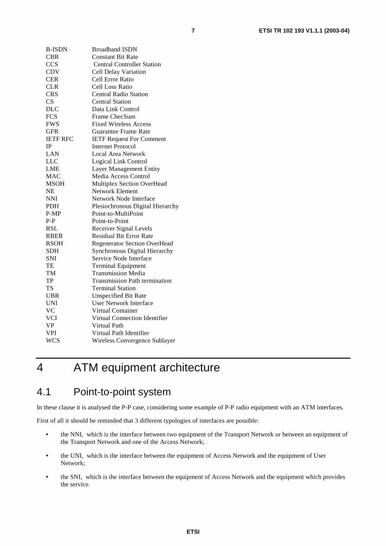
4.1 Point-to-point system In these clause it is analysed the P-P case, considering some example of P-P radio equipment with an ATM interfaces.
First of all it should be reminded that 3 different typologies of interfaces are possible:
• the NNI, which is the interface between two equipment of the Transport Network or between an equipment of the Transport Network and one of the Access Network;
• the UNI, which is the interface between the equipment of Access Network and the equipment of User Network;
• the SNI, which is the interface between the equipment of Access Network and the equipment which provides the service.

ETSI
ETSI TR 102 193 V1.1.1 (2003-04) 8
The functional characteristics of ATM equipment are described in ITU-T Recommendation I.732 [2] using the B-ISDN Protocol Reference Model defined into ITU-T Recommendation I.326 [3] and the equipment modelling derived from ITU-T Recommendation G.805 [4]. This methodology is equivalent to the model used for describing the functions of SDH and PDH equipment defined in ITU-T Recommendation G.783 [5]. The general ATM Network Element functional architecture according to ITU-T Recommendation I.321 [6] model is shown in figure 1.
The main functional layers can be grouped as follows :
• TM - Transmission Media, i.e. the physical layer;
• TP - Transmission Path Termination which terminate a transmission path by extraction or insertion of the appropriate overhead (both SDH and PDH path are applicable);
• VPME, VPE, VP_C - functions related to VP layer;
• VCME, VCE, VC_C - functions related to VC layer.
The physical layer specification for ATM NE (i.e. TM function) shall be compliant to ITU-T Recommendation I.432 [7] for B-ISDN UNI interface types and to ITU-T Recommendation G.707 [15], ITU-T Recommendation G.804 [9], ITU-T Recommendation G.832 [10], ITU-T Recommendation G.957 [11] (for optical interfaces) and ITU-T Recommendation G.703 [13] (for electrical interface) for B-ISDN NNI interface types. This modelling has many advantages, such as the association of any functions to a specific layer and the modularity. figure 2 shows two VP cross-connects linked together via a radio-relay system. The radio system is represented as a "black box".
The simplest radio system is a PDH or SDH system, which may be modelled as shown in figure 3. Only two functions shall be used, the TM and the TP. In fact the first one represents the physical layer, PDH or SDH towards the VP cross-connect and the radio "interface" towards the antennas. In practice this radio equipment is a PDH or SDH equipment which carries transparently an ATM connection with no ATM functionality implemented.
A more complex system is composed by radio equipment which implements ATM functionality, but the simplest ATM equipment shall realize the functions related to VP layer. So in practice the equipment may be a VP switch, VP cross-connect or a VP multiplexer. An example of VP multiplexer with radio interfaces is reported in figure 4.

ETSI
ETSI TR 102 193 V1.1.1 (2003-04) 9
T1520850-96/d03
Non-ATM interface
User/NetworkInterfaces
Transfer functions Layer management functions
Timing
to IWF
Planemanagement
CoordinationFunction
Signalling
ExternalTimingInput
MCF
AEMF
B
A
IWF
AAL SAAL
SAP
Q
F
TMT
TPT TPLM
TMLM
VPMELM
VC_CT
VCE T
VCE T
VCME T
VPCTT
VP_C T
VPME T
AALLM
VC_CLM
VP_C LM
VPET
VPET
VPELM
VPELM
VCPTLM
VCMELM
V
C
ELM
V
C
ELM
VCCTLM VCCTLM VCCTLM
SAP
VCCTT VCCTT TVCCT
NOTE: Layer management of AAl and higher layers is not described in this recommendation.
Figure 1: General functional architecture of an ATM NE according to ITU-T Recommendation I.321 [6] representation

ETSI
ETSI TR 102 193 V1.1.1 (2003-04) 10
VP_CT
VPL_TT
TP/VP_AT
TP_TT
TMT
VP_CLM
VPL_TLM
TP/VPL_AL
TP_TLM
TMLM
ATM interfaces
VP_CT
VPL_TT
TP/VP_AT
TP_TT
TMT
VP_CLM
VPL_TLM
TP/VPL_ALM
TP_TLM
TMLM
ManagementPlane
ManagementPlane
VP Cross-connect VP Cross-connect
Figure 2: Radio link implementing a connection between two VP cross-connect
TP_T T
TM T
T P_T LM
TM LM
TP_T T
R ad io m ed iaT
T P_T LM
R ad io M LM
T P_T T
TM T
TP_T L M
T M LM
TP_T T
Radio
T P_T LM
R ad io M L M
Figure 3: Functional architecture of radio supporting ATM connection
ATM interfacestowards userside
ManagementPlane
VP_CT
VPL_TT
TP/VP_AT
T Radio P_TT
Radio MT
VP_CLM
VPL_TLM
TP/VPL_ALM
T Radio P_TLM
Radio MLMTMT
radio interface
Figure 4: Radio VP multiplexer
In the example of Radio VP multiplexer some functions are labelled with the word "Radio" to point out that these functions should be radio specific since they represent the radio physical layer (i.e. modulation, coding, etc.) and the termination of a Radio path. A better specification of Radio specific ATM functionality required further study.
4.2 P-MP system The modelling of P-MP equipment is more complex, since for an appropriate managing of Radio channel two specific layers are inserted: the DLC layer and the MAC (Media Access Control) layer. The structure depicted in figure 5 refers to a radio system used with the reference architecture shown in figure 6.

ETSI
ETSI TR 102 193 V1.1.1 (2003-04) 11
Service layer (e.g. IP, E1,..)
PHYlayer
PHYlayer
Servicelayer(e.g. IP,E1,..)
BTSTEUserequipment
UNI SNI
Figure 5: Layering structure for P-MP equipment
CS
CCS CRS
R S
A n o t h e r C R S m a y b e c o n n e c t e d t o t h e s a m e C C S
SNI
UNI T S T E
T S T E
T S T E
T E
N e t w o r k N o d e
UNI
T E
T S T E
T S T E
B a s e b a n d i n t e r f a c e r e f e r e n c e p o i n t s SNI/UNI d i r e c t i o n a l a n t e n n a
o m n i d i r e c t i o n a l o r s e c t o r a n t e n n a
UNI
UNI
UNI
UNI
Figure 6: General system architecture
The blocks shown in the figure are:
CS: The Central Station, which interfaces the network. It can be integrated or divided into two units:
i) The Central Controller Station (CCS) also called the exchange unit which is the interface to the local switch;
ii) The Central Radio Station (CRS) also called the radio unit which is the central baseband/radio transceiver equipment. More than one CRS may be controlled by one CCS.
TS: The Terminal Station (outstations with subscriber interfaces). A TS may serve more than one Terminal Equipment (TE).
ETSI
ETSI TR 102 193 V1.1.1 (2003-04) 12
RS:: The Repeater Station (radio repeater outstations with or without subscriber interfaces). An RS may serve one or more TS.
TE: Terminal equipment
SNI: Service Node Interface (EG 202 306 [12] ).
UNI: User Network Interface (EG 202 306 [12]).
The DLC layer contains two sublayers: a Medium Access Control sublayer (MAC) and a Logical Link Control sublayer (LLC). The MAC sublayer implements a service policy that takes into account such factors as channel quality, number of terminal devices and medium sharing with other wireless sub networks. The LLC sublayer maintains the quality of service on a virtual circuit basis. Depending on the type of service provided and channel quality, capacity and utilization, the LLC layer may implement a variety of means including FEC, AR and flow pacing to optimize the service provided to the (DLC) user. Physical layer contains the functions dealing with modulation, coding, etc.
The Wireless ATM Convergence Sublayer (WCS) is defined as a sublayer that generates no protocol but that provides the wireless DLC layer with the information it needs to perform its QoS management functions as required (e.g. the DLC could have parameters: VPI/VCI, cell loss priority, user data).
The Layer Management Entity (LME) of the DLC layer is used to convey traffic contract information and performance requirements between the DLC layer and the higher, connection control functions.
Referring to the general functional architecture of an ATM equipment shown in figure 1, the DLC and MAC layers should be inserted in between the VP layer functions and the physical layer function. Even considering these "extra" layers the reasoning done for P-P is also valid for P-MP systems.
5 Relationship between ATM and TM4 functional specification
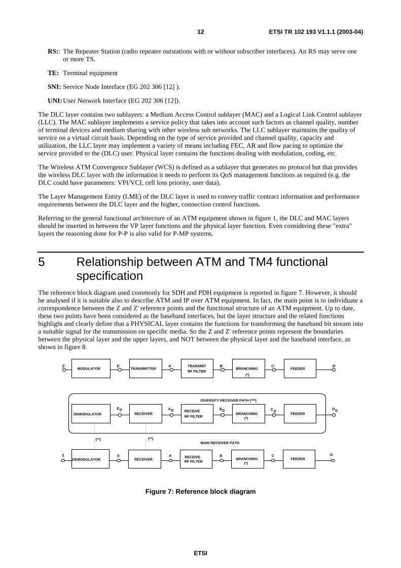
The reference block diagram used commonly for SDH and PDH equipment is reported in figure 7. However, it should be analysed if it is suitable also to describe ATM and IP over ATM equipment. In fact, the main point is to individuate a correspondence between the Z and Z' reference points and the functional structure of an ATM equipment. Up to date, these two points have been considered as the baseband interfaces, but the layer structure and the related functions highlight and clearly define that a PHYSICAL layer contains the functions for transforming the baseband bit stream into a suitable signal for the transmission on specific media. So the Z and Z' reference points represent the boundaries between the physical layer and the upper layers, and NOT between the physical layer and the baseband interface, as shown in figure 8.
MODULATOR TRANSMITTERZ' E' A' TRANSMIT
RF FILTER
B'BRANCHING
C' D'FEEDER
FEEDER
FEEDER
BRANCHING
BRANCHING
RF FILTER
RF FILTER
RECEIVERRECEIVE
DEMODULATOR
ED AD DB
(*)
CDDD
D
(*)
CBRECEIVEARECEIVER
(**)(**)
EDEMODULATOR
Z
MAIN RECEIVER PATH
DIVERSITY RECEIVER PATH (***)
(*)
Figure 7: Reference block diagram
ETSI
ETSI TR 102 193 V1.1.1 (2003-04) 13
E'
A'
B'
C'
D'
T Radio_TT
Modulator
Transmitter
Tx RF Filter
Branching
Feeder
TP/VP_AVP layer
Physicallayer
Z`
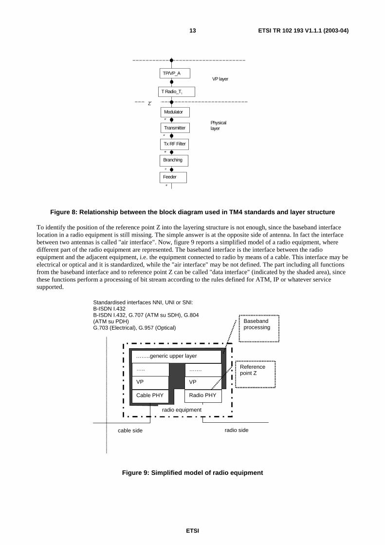
Figure 8: Relationship between the block diagram used in TM4 standards and layer structure
To identify the position of the reference point Z into the layering structure is not enough, since the baseband interface location in a radio equipment is still missing. The simple answer is at the opposite side of antenna. In fact the interface between two antennas is called "air interface". Now, figure 9 reports a simplified model of a radio equipment, where different part of the radio equipment are represented. The baseband interface is the interface between the radio equipment and the adjacent equipment, i.e. the equipment connected to radio by means of a cable. This interface may be electrical or optical and it is standardized, while the "air interface" may be not defined. The part including all functions from the baseband interface and to reference point Z can be called "data interface" (indicated by the shaded area), since these functions perform a processing of bit stream according to the rules defined for ATM, IP or whatever service supported.
……..generic upper layer
Radio PHY
VP
…….
Cable PHY
VP
…..
radio side cable side
Standardised interfaces NNI, UNI or SNI: B-ISDN I.432 B-ISDN I.432, G.707 (ATM su SDH), G.804 (ATM su PDH) G.703 (Electrical), G.957 (Optical)
Reference point Z
radio equipment
Baseband processing
Figure 9: Simplified model of radio equipment

ETSI
ETSI TR 102 193 V1.1.1 (2003-04) 14
(*) NO FILTERING INCLUDED
(**) ALTERNATIVE CONNECTION AT RF, IF OR BASEBAND
(***) OPTION NOT CONSIDERED BY THIS ETS
MODULATOR TRANSMITTERZ' E' A' TRANSMIT
RF FILTERB'
BRANCHINGC' D'
FEEDER
FEEDER
FEEDER
BRANCHING
BRANCHING
RF FILTER
RF FILTER
RECEIVERRECEIVE
DEMODULATORED AD DB
(*)
CD DD
D
(*)
CBRECEIVEARECEIVER
(**)(**)
EDEMODULATOR
Z
MAIN RECEIVER PATH
DIVERSITY RECEIVER PATH (***)
(*)
X'
X
DATAINTERFACE
DATAINTERFACE
Figure 10: New block diagram for radio equipment
This distinction allows us to determine which parts represents the radio specific requirements (e.g. BER, sensitivity, etc.) allocated from the reference point Z to the reference point D, which the requirements specific for SDH, ATM, IP over ATM functions allocated to the block "data interface" and the baseband interface identified with the reference point X.
This proposal solves only one aspect of the problem, since the testing of the radio requirements is left open and also the definition of bit rate.
Before continuing the discussion, it should be noted that for P-MP systems the reference point Z is not the boundary between the physical layer and the VP layer, but it is the limit between the MAC layer and the upper layers (see figure 5). This fact is important for the definition of bit rates, for system requirement definition and for conformance test specification. These specific radio layers (MAC, DLC) are not part of the "data interface" functional block, which represents the processing associate to the general functional layers, i.e. the media independent functions, so an additional P-MP baseband processing functional block and the corresponding reference point might be inserted.
6 Bit rate definition In the previous clause a new block diagram is proposed where the main reference points are:
• Z and Z' at the interfaces of the physical layer;
• X and X' at the data interfaces NNI, UNI or SNI;
• D and D' at the air interfaces.
The BER parameter is the basic parameter used to define the majority of radio requirements, so an unambiguous definition is desirable to avoid any misunderstanding in defining the requirements.
In the generic wording the gross bit rate is used to identify the bit rate at the reference point D, while the terms system capacity, baseband capacity and transmission capacity are often used to indicate the bit rate at the baseband interface. These alternative terms may cause a misinterpretation when a layering structure is introduced, for example, to describe P-MP system. This potential confusion may be eluded using different definition for reference point X and Z.

ETSI
ETSI TR 102 193 V1.1.1 (2003-04) 15
The reference point X represents the standardized baseband interface, which may be a NNI, UNI or SNI, so the naming of the capacity at this point is "data bit rate". For example, for PDH the bit rates are those defined by ITU-T Recommendation G.703 [13] , for SDH they are the STM-N rates defined by ITU-T Recommendation G.707 [15] .One should not mix data capacity with payload capacity. The payload capacity is the capacity carried by a signal that might be at a lower bit rate than the data capacity. For example, the payload capacity for a system with an STM-1 baseband (data) capacity might be a STM-0 or a 2 Mbit/s, or a 34 Mbit/s or a 140 Mbit/s, but the data capacity remains STM-1 in all cases. The case of a 2 Mbit/s interface in SDH equipment represents a 2 Mbit/s baseband (data) capacity, while the STM-1 rate is the baseband (data) interface on the other side of the equipment and the payload bit rate might be STM-1 or STM-0.
Now the more appropriate name for the capacity at the reference point Z should be found, even if it may be more difficult. In fact this capacity represents the capacity that is transmitted. In case of PDH equipment this capacity corresponds to the PDH baseband capacity itself, while in case of SDH equipment this capacity corresponds to the baseband interface just in case of STM-N baseband interface. If the baseband interface is ATM, the situation is similar to the SDH case, since the ATM may be carried by SDH (see. ITU-T Recommendation G.707 [15]) or by PDH (see ITU-T Recommendation G.804 [9]).
Generally speaking, the bit rate is strictly connected with bit timing, while the BER is connected to " information bit" which may be a subset of bit stream.
The bit rates can be defined as follows:
1) The data bit rate is the bit rate at the reference point X corresponding to the baseband interface which can be a NNI, UNI or SNI. According to the type of interface the following requirement are applicable:
- for the PDH interface the bit rate is defined by ITU-T Recommendations G.704 [14] and ITU-T Recommendation G.703 [13]. They are 2,048 Mbit/s, 8,448 Mbit/s, 34,368 Mbit/s and 139,264 Mbit/s;
- for the SDH interface the bit rate is defined by ITU-T Recommendation G.703 [13], and ITU-T Recommendation G.707 [15]. They are Nx155,52 Mbit/s, where N=1, 4, 16, 64...
- for the ATM NNI the bit rate is defined by ITU-T Recommendation G.707 [15]. They are Nx155,52 Mbit/s, where N=1,4,16,64…..
- for the ATM UNI the bit rate is defined by ITU-T Recommendations I.432 [7], G.804 [9], ETS 300 742 [16], ETS 300 811 [17], ETS 300 299 [18], ETS300 300 [19]. They are 2,048 Mbit/s (PDH), 51,84 Mbit/s, 25,600 Mbit/s, 155,52 Mbit/s (SDH) and 622,08 Mbit/s (SDH);
- for IP for further study.
2) The data transmission bit rate is the bit rate transmitted at the reference point Z.
3) The gross bit rate is the bit rate transmitted over the air at the reference point D, D', etc. … In the case of a transmitter operating in burst mode, the gross bit rate is the instantaneous maximum bit rate during the burst. The gross bit rate has an unique relation to the symbol rate through the implemented modulation format.
Note: the bit rate at reference points A, B, C and D is the same.
4) Payload bit rate is the bit rate carried by higher hierarchy at any reference point. At the baseband interface the payload capacity depends on the type of interfaces, for example for SDH NNI interface the payload is the PDH rates or ATM cells stream carried by SDH frame.
6.1 Relationship between bit rates The relationship between the bit rates at the different reference points is fundamental to define the requirements, since TM4 requirements are generally refer to the BER, i.e. to the errors occurring within a specific bit stream under specific conditions. The layering structure and the identification of precise and unique reference point allows us to identify the bit stream, but it may be not enough. In order to explain this point, we will consider two examples: a SDH and an ATM equipment.

ETSI
ETSI TR 102 193 V1.1.1 (2003-04) 16
Let us suppose we have a SDH equipment with STM-1 interfaces on both radio and cable interface. This equipment implements a multiplex section and the equipment model, defined by EN 300 417 [20], is shown in figure 11. At any boundary between the layers the bits considered are different: at multiplex layer the bits belonging to the MSOH and to the payload area are treated; at regenerator layer the bits belonging to the RSOH, to the MSOH and to the payload area are treated; at physical layer all bits are considered. Formally, the bit rate at any layer is different, but at reference point X (i.e. the SDH NNI interface) and Z the bit rate is the same, while at reference point D is greater due to channel coding. This SDH equipment may carry VC-12, VC-2, VC-4 containers, i.e. 2 Mbit/s, 34 Mbit/s and 140 Mbit/s bit rates, which are the payloads, while the transmission capacity is STM-1 and it corresponds to the baseband interface.
Now let us consider an SDH equipment with 140 Mbit/s PDH baseband interface, i.e. at reference point X. In this case the transmission capacity is STM-1 with a 140 Mbit/s PDH payload, the data interface is a PDH 140 Mbit/s and the gross bit rate is the same of the previous equipment. Hence, from the point of view of radio-electrical requirements, the two equipments are the same, while the SDH functions, i.e. the data processing, are different. In table 1 the bit rate at any reference points for an SDH equipment with a PDH interface is shown.
MS
RS
Physical Optical electrical
Reference Points Z, Z`
Reference Point X SDH NNI Interface
Reference Point X SDH NNI Interface
Reference Points D, D`
Physical Optical electrical
Physical radio
Figure 11: Example of SDH radio equipment
Table 1: Bit rates at any reference points for a SDH equipment with STM-1 interface and with PDH interface
Reference points
in figure 11
Bit rate Bit rate
X,X 155,52 [Mbit/s] (STM-1) 139,264 Mbit/s (PDH) Z,Z' 155,52 [Mbit/s] (STM-1) 155,52 Mbit/s (STM-1) D,D' 155,52×R [Mbit/s] 155,52×R [Mbit/s] NOTE: R represents the redundancy due to channel coding.
Now let us suppose to have an ATM equipment that implements NNI interfaces, for example an ATM over STM-1 (see figure 12). In this case the bit rate at reference points X and Z is 155,52 Mbit/s, while at reference point D it is 155,52 Mbit/s increased by redundancy introduced by channel coding.

ETSI
ETSI TR 102 193 V1.1.1 (2003-04) 17
VP
TP Termination Path
Physical Optical electrical
Reference Points Z, Z`
Reference Point X ATM NNI Interface
Reference Point X ATM NNI Interface
Reference Points D, D`
Physical Optical electrical
Physical radio
Figure 12: Example of ATM equipment termination VP connection with ATM NNI interface (ITU-T Recommendations G.804 [9], G.803 [8], G.957 [11])
Let us consider a P-MP system with terminal equipment having an E1 UNI interface and the base station with an interface ATM STM-1 NNI. The bit rate at reference point X, i.e. the output/input of terminal equipment is 2 Mbit/s while at reference point X' is 155,.52 Mbit/s. The gross bit rate at reference point A, A' corresponds to the bit rate given by the bit rate at the coder input plus any redundancy introduced by coder and modulator. In practice the gross bit rate can be obtained by the symbol rate multiplied by number of bits transmitted per symbol. So even in downlink and uplink the gross bit rate is the same.
The data transmission bit rate is the bit rate referred to the information which is decoded/undecoded and modulated/demodulated, i.e. the information flow which goes into/comes out from the physical layer. In case of a P-MP system the data transmission bit rate includes the additional overhead related to the Convergence Layer, DLC and MAC Packet Data Unit.
ETSI
ETSI TR 102 193 V1.1.1 (2003-04) 18
VP
TP Termination Path(termination of SDHpath,i.e. RS, MS,Path termination)
Physicalelectrical
Reference PointsZ, Z`
Reference Point XATM UNI E1Interface
Reference Point X'ATM STM-1 NNIInterface
Reference Points D,D`
PhysicalOptical
Physicalradio
VC
AAL1
TP TerminationPath (DLC, MAClayer)
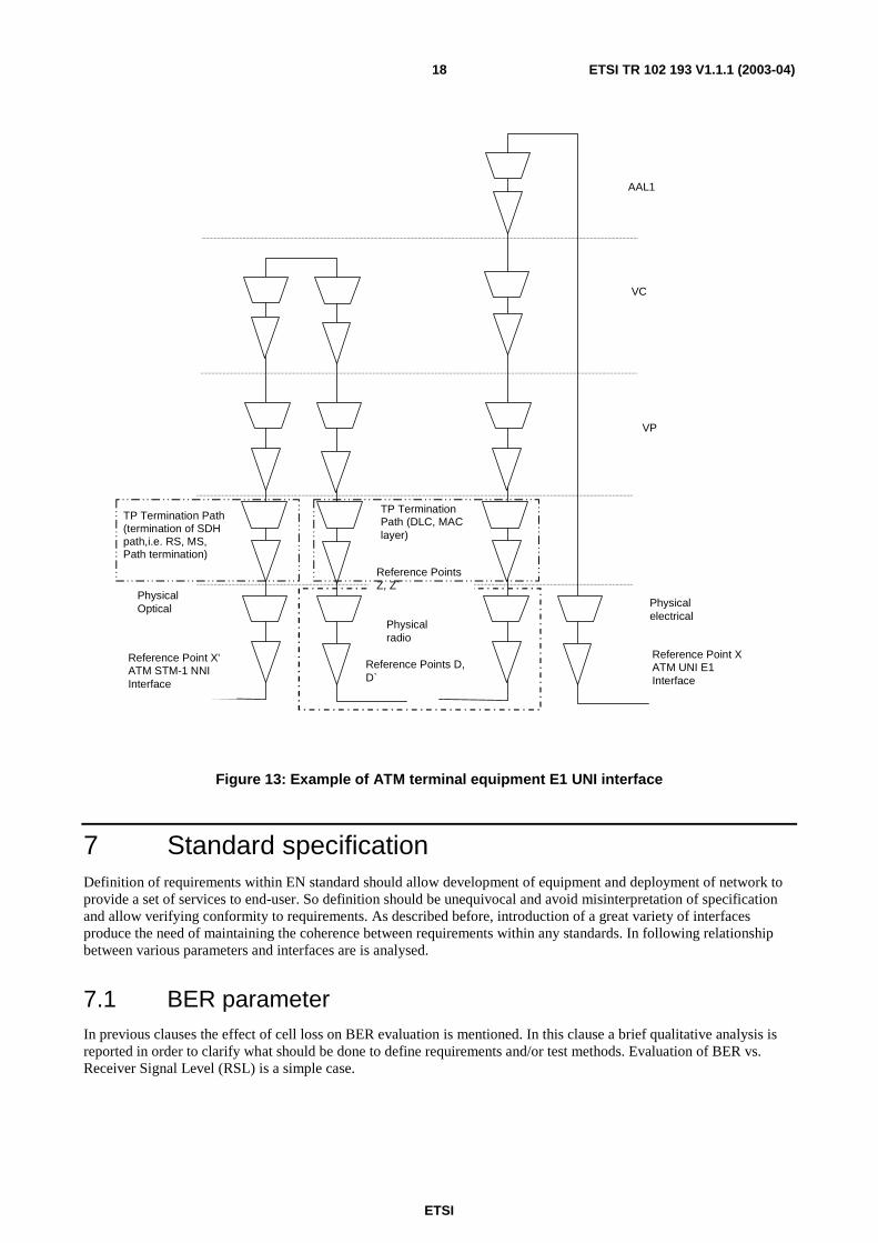
Figure 13: Example of ATM terminal equipment E1 UNI interface
7 Standard specification Definition of requirements within EN standard should allow development of equipment and deployment of network to provide a set of services to end-user. So definition should be unequivocal and avoid misinterpretation of specification and allow verifying conformity to requirements. As described before, introduction of a great variety of interfaces produce the need of maintaining the coherence between requirements within any standards. In following relationship between various parameters and interfaces are is analysed.
7.1 BER parameter In previous clauses the effect of cell loss on BER evaluation is mentioned. In this clause a brief qualitative analysis is reported in order to clarify what should be done to define requirements and/or test methods. Evaluation of BER vs. Receiver Signal Level (RSL) is a simple case.
ETSI
ETSI TR 102 193 V1.1.1 (2003-04) 19
7.1.1 Example of SDH equipment
The BER vs. RSL curve can be measured at reference point Z and X (see figure 10). In case of SDH STM-1 equipment, bits at reference point Z and X are the same, note that the information carried is not the same: as consequence the curves evaluated at two points are the same. It should be noted that this is true considering the statistical distribution of error or burst, which are distributed according to Poisson distribution: in this case the probability that a burst starts in a specific bit is statistical independent. Considering a long period of time, the error probability evaluated on the whole bit stream or in a portion of the bit stream does not change. The same conclusion can be reached considering an SDH equipment with PDH interfaces.
7.1.2 Example of ATM equipment
Let us now consider a P-MP system with a STM-1 ATM NNI interface at the network side and a E1 at the UNI interface. The systems can be described using atomic function as shown in figure 14 (the model is not formally correct, since SDH layer is not split in RS, MS functions, furthermore DLC and MAC layers are not shown separately, but it shows what is required for the purpose of the present document). Clearly the bit rates at NNI and UNI are defined and they are 155,52 Mbit/s and 2,048 Mbit/s respectively. Then the question is "which is the bit rate at reference point Z and D?". In fact in order to define the requirements, this bit rate should be defined. As a thumb rule, the bit rate at reference point D (or A) corresponds to the bit rate at reference point Z multiplied by code redundancy, and it can be defined as "gross bit rate". This approach does not solve the open point, since the bit rate at reference point Z should be defined. In a P-P system, this bit rate is very closed to the data interface bit rate, while in P-MP it is a portion of it. So a suitable definition should be found.
The second step to be considered is the BER definition. I would like to remind that BER means Bit Error Ratio and it is connected to the bit stream considered and bit rate has no impact on BER. Referring to figure 14, at Point Q, which identifies the interface between physical layer and SDH regenerator section, information transmitted is composed by SDH frame carrying ATM cell (See figure 15A). At points K, which represents the interface between SDH layer and VP ATM layer, information is composed by ATM cells (see figure 15B). At points W and J, between VP ATM layer and Transmission Convergence layer, information is again composed by ATM cells. At reference point Z, between MAC layer and coder, information is composed by PDU (Protocol data Unit) carrying ATM cells or ATM payload (see figure 15C). Finally, at point R information is the 2 Mbit/s stream.
Now, let us suppose that some errors occur on radio channel and let us consider the downstream. figure 16A shows the PDU stream received at point Y. The red squares represent the errored bits on bit stream due to radio channel, while the other full squares represent the ATM cells carried by PDU packets. MAC and DLC process these PDU. We can suppose that PDU packet #3 with error in the header is discarded by these layers, so the ATM cell transported are lost. The bit stream at point J is composed by ATM cells, less those discarded by lower layer (see figure 16B). The VP and VC layer process the ATM, so ATM cell with errors within the header is discarded. The ATM cells stream at the input of ALL1 layer does not contains the cells discarded by lower layers (i.e. VP and DLC/MAC) (see figure 16C). So, in order to maintain bit-integrity ALL1 inserts dummy bits at its output toward the AAL user (see figure 16D). As a consequence, if the dummy bits sequence is enough long, the user receiving E1 signal detects an AIS. Hence few errors at radio physical layers may produce an higher bit rate.
Additional conclusions are that:
• BER at radio physical layer and at UNI and NNI interface is clearly different;
• definition of requirements and definition of conformance testing should take into account this behaviour;
• equipment standard should contain definition of ATM, IP functionality;
• ATM and IP functionality should be verified in order to check their applicability to radio system.

ETSI
ETSI TR 102 193 V1.1.1 (2003-04) 20
VP
TP Termination Path(termination of SDHpath,i.e. RS, MS,Path termination)
Physicalelectrical
Reference PointsZ, Z`
Reference Point XATM UNI E1Interface
Reference Point X'ATM STM-1 NNIInterface
Reference Points D,D`
PhysicalOptical
Physicalradio
VC
AAL1
TP TerminationPath (DLC, MAClayer)
Point K Point W
Point J
Point Y
Point Q
Point R
Point M
Figure 14: Example of ATM terminal equipment E1 UNI interface

ETSI
ETSI TR 102 193 V1.1.1 (2003-04) 21
ATM cell
SDH Frame
(A)
ATM cell
ATM cell stream
(B)
PDU packet stream
PDU packet
(C)
Figure 15: Information at various reference point

ETSI
ETSI TR 102 193 V1.1.1 (2003-04) 22
(C) ATM cells stream and equivalent bitstream at point Q
Bits belonging to thesame ATM payloadcell
PDU #1 PDU #2 PDU #3
Errored bit
Errored bit
ATM cells
(A) PDU received at point Y
(B) ATM cell stream received at point J
Cells delete byDLC due to errorsin PDU Header
ATM cell discarded byVP functions due toerrors in ATM header
ATM cellwithouterrors
Errored bit
Errored bit
Bit deletedsince theybelonged toa discardedcell
Bits belonging to thesame ATM payloadcell
Dummy bits inserted by AAL1 instead ofbit belonging to lost/discaded to maintainbit integrity (bits "1" ) (See I.636.1)
(D) bit stream at point R
ATM cell
Figure 16: Relationship between errored bits at various reference points
8 Conformance test An example of configuration for testing an ATM P-MP equipment with ATM Forum 25 Mbit/s interface is shown in figure 17. With this configuration all ATM performance parameters such as Cell Loss Ratio (CLR), Cell Error Ratio (CER), Cell Delay Variation (CDV), etc., can be measured vs. variation of attenuation A. It should be noted that the BER is evaluated by the ATM analyser and generally may be evaluated on the payload of ATM cell or on bit stream including the ATM overhead, considering or excluding the discarded cell. So the BER curve vs. receiver power, which can be evaluated by means of attenuation A, does not refer to the reference point Z, but to reference point X. Taken into account the ATM functions implemented into Network Termination (NT) the BER curve should be derived indirectly.
If is available only IP over ATM interface, the evaluation of ATM requirement (CER, CLR, etc.) is not possible, since the cell stream is not available.

ETSI
ETSI TR 102 193 V1.1.1 (2003-04) 23
ET155
ET155 ET155
ATM
ET155
Radio Radio
ATM
1 5 5
2 5
2 5
Analizzatore ATM
25 25 Eth
N T
25 25 Eth
N T
C.E T2
C .ET3 A1.ET1
T.STM 1 T.ATM F1
T.ATM F2
NT2.R adioIF
NT1.R adio IF
N T2.ATM F1
NT1.A TM F1
NT1.A TM F2
A
Figure 17: Example of measurement of ATM equipment with 25 Mbit/s ATM Forum interface on user terminal
For the IP over ATM test the situation is quite complex since the factor that may influence the results are many. In order to reduce the variability of results and of tests condition, as reference, the benchmark test defined by RFC Recommendations should be used. The tests defined by IETF RFC can be easily performed on radio system, but the influence of BER shall be considered. The main idea under the proposal presented in this contribution is to use as references the tests and the results obtained for E1 interface. In fact, in case of IP port the factor influencing the results are:
• the configuration of the IP port, for example the peak rate of the IP port;
• in case of IP over ATM the ATM class of service, such as CBR, UBR, GFR, etc.;
• the IP packet size, i.e. from 64 bytes to 1 528 bytes per frame;
• the IP traffic characteristics, i.e. constant, burtsy, random.
The IETF RFC helps us, since these recommendations define standardized tests which are worldwide used. Additionally E1 results help us to find some measurable and unique reference points, i.e. the received power corresponding to a given BER on E1. These values allows to repeat the tests under precise and repeatable conditions, measuring performance parameters defined for IP, such as less-loss throughput, frame loss, etc.
8.1 Packet level performance tests IP protocol is considered the universal level 3 end-to-end protocol. It is operable over different level 2 protocol, as ATM or Ethernet.
The main part of offered services from broadband systems are founded on IP technology. The devices should be equipped with Ethernet interface (10/100 base T) towards the users, and ATM interface (better 155Mb/s) towards the Switched Core Network. To evaluate performance parameters of the systems it must be known the entire protocol stack supported from the system on Network Termination and Base Station, and particularly:
• The type of encapsulation of IP packets over ATM cells (bridged or routed; VC Multiplexing or LLC SNAP; with or without FCS if bridged);
• The general interface characteristics to MAC layer.

ETSI
ETSI TR 102 193 V1.1.1 (2003-04) 24
The benchmarking methodologies requested in this document are specified in the following IETF RFC:
• IETF RFC 2684 [34], defining Multiprotocol Encapsulation over ATM Adaptation Layer 5;
• IETF RFC 1242[35] or RFC 2285[36] and RFC 2544[37], defining Benchmarking Terminology for Network Interconnection Devices;
• IETF RFC 2225[38], defining classical IP and ARP over ATM.
The tests can be performed in following configuration:
• ATM-to-LAN;
• LAN-to-ATM;
• LAN-to-LAN.
The configuration for ATM-to-LAN and LAN-to-ATM is the same used for test on E1interface. For a P-MP system with LAN interface on TS and ATM interface on CRS, an example of configuration for a LAN-to-LAN test is shown in figure 18. It is important to point out that in these test it is required to close in loop the ATM connection carrying over the LAN traffic on the CRS side. The results represent the QoS perceived by the end user in case of a end-to-end LAN connection transported in downlink and uplink by a P-MP system. The measurements LAN-to-ATM or ATM-to-LAN allow testing the performance of uplink and downlinking separately.
For a P-P system, considering that the characteristics are symmetric for the direction from terminal A to terminal B and vice versa, and probably the interface on both terminal are the same, i.e. IP or ATM, the test can be performed just in one direction.
ATM STM-1
Indoor RT
Indoor BTS
Outdoor BTS
Outdoor RT
Eth10baseT
AA
Waveguide
AA
AA
downlink
uplink
Outdoor BTS(downlink interferer)
Outdoor RT
BSTS
Indoor RT
ATM Switch
VC/VP 1
VC/VP 2
TS
TS
ATM STM-1
Indoor RT
Indoor BTS
Outdoor BTS
Outdoor RT
Eth10baseT
AAAA
Waveguide
AAAA
AAAA
downlink
uplink
Outdoor BTS(downlink interferer)
Outdoor RT
BSTS
Indoor RT
ATM Switch
VC/VP 1
VC/VP 2
TSTS
TSTS
Figure 18: Test configuration for LAN-to-LAN measurement for interference sensitivity for downlink channel
8.2 Full band throughput The allowed maximum capacity of IP connection at the 10/100BaseT interface, i.e. the maximum bit rate, for downlink and uplink, can be measured under different conditions. As above described for a P-MP system the tests should be performed on uplink (i.e. LAN-to-ATM) and downlink (i.e. ATM-to-LAN) and of the whole system (LAN-to-LAN).

ETSI
ETSI TR 102 193 V1.1.1 (2003-04) 25
The unidirectional throughput defined as the maximum loss-less rate through the device under test according to IETF RFC 1242 [35] and IETF RFC 2544 [37] should measured under following test condition:
• for MAC frame size of 64 bytes, 128 bytes, 256 bytes, 512 bytes, 1 518 bytes;
• for input traffic distribution constant with related parameters (additional tests under other traffic distribution such as, burst, Poisson);
• for various ATM connection type supported, e.g. CBR, UBR, ABR, etc. with related parameters.
For a radio system a reference parameter is BER, but as described in clause 7 the protocol stack implemented within the system under test influences the BER. In order to overcome this potential ambiguity and to guarantee the repeatability, it may introduce a reference test condition. The P-P and P-MP system may have an E1 interface available on TS, which can be used to define a reference condition. In fact performed a measurement of the received power versus s a BER is well known and the obtained results are worldwide comprehensible. In clause 7 is reported the effect of a cell loss on a BER, but the phenomena is comprehensible and also repeatable. So, first of all, the received power vs. BER curve for the E1 interface can be measured. Then the obtained can be used to identify some reference points, for example, the RSL points at BER less or equal to 10-4, 10-6 and 10-9 or any other values which can be considered suitable. For any of this points a corresponding received power can be identified, as shown in figure 19.
Rx1
BER=10-6
BER=10-9
BER=10-3
Rx2 Rx3
Figure 19: BER vs. received power measured at E1 interface
Moreover, for a good comprehension of the results, the following information should be taken into account:
• at what level the throughput is measured, i.e. MAC, Ethernet, ATM, IP;
• if the results are obtained for LAN-ATM, ATM-LAN, LAN-LAN tests;
• trial duration;
• the ATM encapsulation type.
ETSI
ETSI TR 102 193 V1.1.1 (2003-04) 26
8.2.1 Interference condition
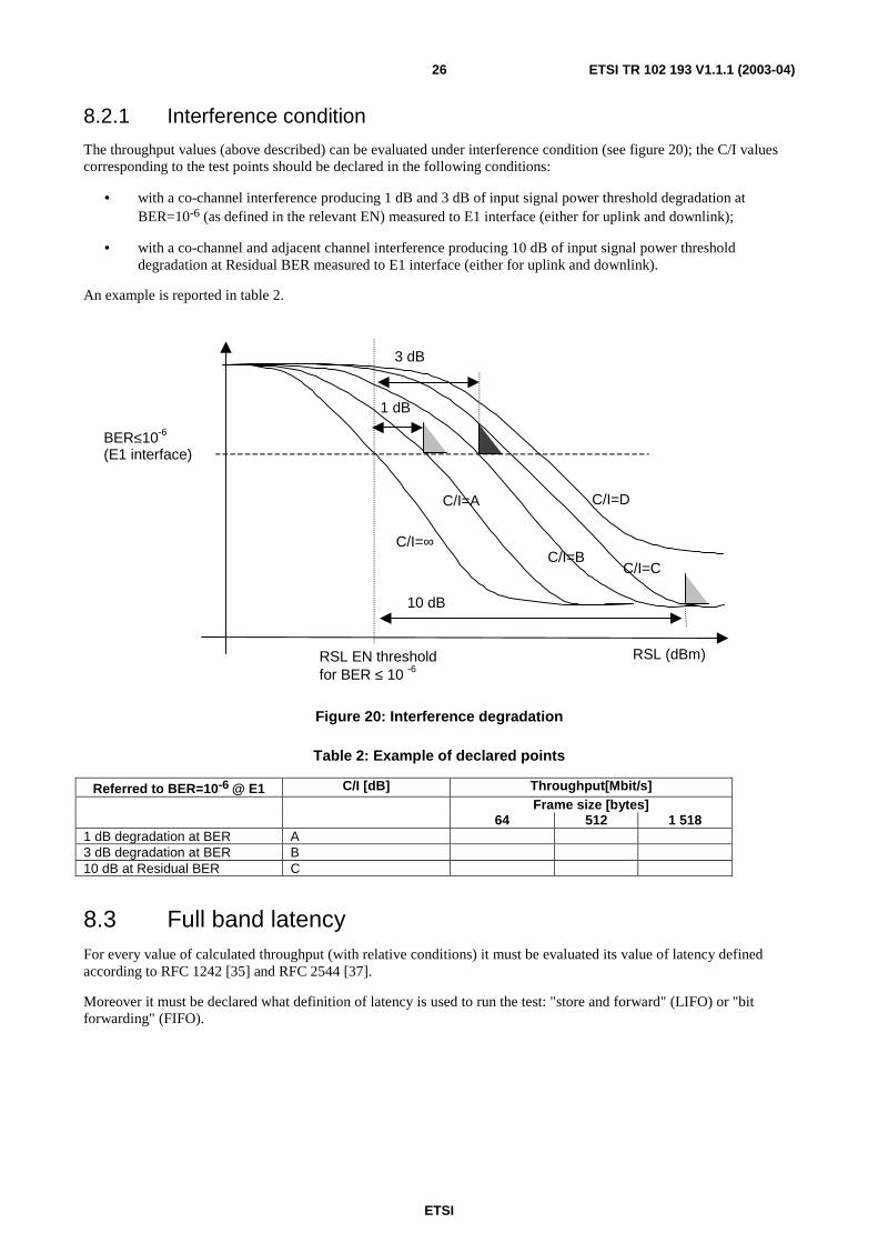
The throughput values (above described) can be evaluated under interference condition (see figure 20); the C/I values corresponding to the test points should be declared in the following conditions:
• with a co-channel interference producing 1 dB and 3 dB of input signal power threshold degradation at BER=10-6 (as defined in the relevant EN) measured to E1 interface (either for uplink and downlink);
• with a co-channel and adjacent channel interference producing 10 dB of input signal power threshold degradation at Residual BER measured to E1 interface (either for uplink and downlink).
An example is reported in table 2.
10 dB
3 dB
1 dB
C/I=∞
C/I=A
C/I=B C/I=C
C/I=D
BER≤10-6
(E1 interface)
RSL (dBm) RSL EN threshold for BER ≤ 10 -6
Figure 20: Interference degradation
Table 2: Example of declared points
Referred to BER=10-6 @ E1 C/I [dB] Throughput[Mbit/s] Frame size [bytes] 64 512 1 518
1 dB degradation at BER A 3 dB degradation at BER B 10 dB at Residual BER C
8.3 Full band latency For every value of calculated throughput (with relative conditions) it must be evaluated its value of latency defined according to RFC 1242 [35] and RFC 2544 [37].
Moreover it must be declared what definition of latency is used to run the test: "store and forward" (LIFO) or "bit forwarding" (FIFO).

ETSI
ETSI TR 102 193 V1.1.1 (2003-04) 27
History Document history
V1.1.1 April 2003 Publication


![Point-to-Multipoint and Multipoint-to-Multipoint · PDF filedefined by IEEE 802.1Qay [2] is representative carrier Ethernet . Abstract — We have implemented point-to-multipoint (PtMP)](https://img.dokumen.tips/doc/110x75/5a75c0147f8b9a4b538cb6cd/point-to-multipoint-and-multipoint-to-multipoint-defined-by-ieee-8021qay.jpg)