Embed Size (px)
Citation preview

Meggitt SA, Route de Moncor 4, Case postale, 1701 Fribourg, Switzerland Tel: +41 26 407 11 11Fax: +41 26 407 13 01
[email protected]/energy
www.meggitt.com
Information contained in this document may be subject to export control regulations of the European Union, USA or other countries. Each recipient of this document is responsible for ensuring that transfer or use of any information contained in this document complies with all relevant export control regulations. ECN N/A.
DATA SHEET
IECEx KGS
TQ902 / TQ912, EA902 and IQS900 proximity measurement chain
KEY FEATURES AND BENEFITS
• From the vibro-meter ® product line
• Non-contact measurement based on eddy-current principle
• Available in standard versions and Ex versions certified for use in hazardous areas (potentially explosive atmospheres)
• Conforms to API 670 5th edition
• 1, 5 and 10 m chains
• Temperature-compensated design
• Voltage output or current output with short-circuit protection
• Current-signal transmission over distances up to 1 km
• Frequency response: DC to 20 kHz (−3 dB)
• Linear measurement range: 2 or 4 mm
• Temperature range (sensor): −40 to 180 °C
KEY FEATURES AND FEATURES (continued)
• Optional diagnostic circuitry detects sensor, cabling and/or signal conditioner problems
• Suitable for use in functional safety contexts: SIL 2 in accordance with IEC 61508 and Cat 1 PL c in accordance with ISO 13849
• IQS900: Removable screw-terminal connectors and DIN-rail mounting
APPLICATIONS
• Shaft relative vibration and gap/position measurement chains for machinery protection and/or condition monitoring
• Ideal for use with VM600 and/or VibroSmart ®
machinery monitoring systems
• API 670 applications
• Safety-related applications
• Speed (tachometer) sensor/measurement chain for overspeed detection system (ODS) applications
IQS900signal conditionerTQ912 sensor
(reverse mount)
TQ902 sensor(standard mount)
(Images not to scale)

DATA SHEETTQ902 / TQ912, EA902 and IQS900 proximity measurement chain2 / 21
Document reference DS 265-101Version 6 – 20.01.2022
DESCRIPTION
IntroductionThe TQ902 / TQ912, EA902 and IQS900 form proximity measurement chains, from Meggitt’s vibro-meter ® product line.
TQ9xx-based proximity measurement chains allow contactless measurement of the relative displacement of moving machine elements, and provide an output signal proportional to the distance between the sensor tip and the target. Accordingly, these measurement chains are ideally suited for measuring the relative vibration and axial position of rotating machine shafts, such as those found in steam, gas and hydraulic turbines, as well as in alternators, turbo-compressors and pumps.
A TQ9xx-based proximity measurement chain consists of a TQ9xx proximity sensor, an optional EA90x extension cable and an IQS900 signal conditioner, configured for a particular industrial application. The EA90x extension cable is used to effectively lengthen the front-end, as required. Together, these form a calibrated proximity measurement chain in which each component is interchangeable.
The IQS900 signal conditioner is a versatile and configurable device that performs all required signal processing and generates the output signal (current or voltage) for input to a machinery monitoring system such as a VM600 or VibroSmart ®. In addition, the IQS900 supports optional diagnostic circuitry (that is, built-in self-test (BIST)) that automatically detects and remotely indicates problems with a measurement chain.
TQ902 / TQ912 sensors and cablingThe active part of a TQ9xx proximity sensor is a coil of wire that is moulded inside the tip of the device, made of PPS (polyphenylene sulfide), a high-performance, high-temperature engineering thermoplastic. The sensor body is made of stainless steel. The target material must, in all cases, be metallic.
The TQ902 and TQ912 proximity sensors are essentially the same except that the TQ902 is for standard-mount and the TQ912 is for reverse-mount applications. Both sensor bodies are available with metric or imperial threads and have an integral coaxial cable terminated with a
self-locking miniature coaxial connector. A TQ9xx sensor’s integral cable and the EA90x extension cables are available in various lengths, which can be combined to obtain a particular total system length (TSL) for an application.
Optional interconnection protectors (IP172), junction boxes (JB118) and other housings are available for the mechanical and environmental protection of the connection between a TQ9xx sensor’s integral cable and an EA90x extension cable.
IQS900 signal conditionerThe IQS900 signal conditioner contains a high-frequency modulator/demodulator that supplies a driving signal to a TQ9xx sensor. This generates an electromagnetic field in the tip of the senor, which generates eddy-currents in the metallic target. When the target moves, the eddy-currents change, which causes a change in the electrical characteristics of the TQ9xx that the signal conditioner converts into a signal that is proportional to the distance to the target.
The IQS900’s output is an analogue signal consisting of a dynamic component (AC) that corresponds to the measured vibration (displacement) and a quasi-static component (DC) that corresponds to the measured gap. The output can be configured as a current or a voltage signal, suitable for transmission to a monitoring system via current (2-wire) or voltage (3-wire) transmission cables, respectively.
For an IQS900 signal conditioner with optional diagnostics, the quasi-static DC component also functions as a diagnostic indicator. That is, the IQS900’s diagnostic circuitry continuously checks the integrity of the measurement chain and will drive the measurement/diagnostic component (DC) outside of its normal operating range to indicate a problem with the sensor, the cabling and/or the signal conditioner itself.
For test purposes, the IQS900 includes a “raw” voltage output signal and a test input signal that allow the measurement chain/system operation to be tested in situ, thereby simplifying commissioning and troubleshooting.
Document reference DS 265-101Version 6 – 20.01.2022
DATA SHEETTQ902 / TQ912, EA902 and IQS900 proximity measurement chain
3 / 21
DESCRIPTION (continued)
Application informationAn IQS900 signal conditioner with diagnostics automatically and remotely indicates the health/status of a TQ9xx-based measurement chain so you always know when measurements can be trusted. This helps to ensure that machinery is operated safely and reliably, extending its life and reducing costs.
Equally important, TQ9xx-based measurement chains using an IQS900 with diagnostics are SIL 2 “by design” so they bring enhanced reliability and significant risk reduction, making them suitable for use in safety-related applications (functional safety contexts).
Further, TQ9xx-based measurement chains are form, fit and functionally equivalent replacements that match or better the outstanding
performance of TQ4xx-based measurement chains. Each component is interchangeable, so existing TQ4xx-based proximity measurement chains can be quickly and easily replaced or upgraded. For example, an IQS900 signal conditioner without diagnostics is a direct replacement for an IQS45x in most TQ4xx-based measurement chains.
Note: A TQ9xx-based measurement chain using an IQS900 configured with a current output and a GSI127 galvanic separation unit, allows transmission over distances up to 1 km – longer than any other solution.
For specific applications, contact your local Meggitt representative.
SPECIFICATIONS
Overall proximity measurement chainOperationSensitivity• Ordering option code B21 : 8 mV/ µm (203.2 mV/ mil) • Ordering option code B22 : 2.5 µA / µm (63.5 µA / mil) • Ordering option code B23 : 4 mV/ µm (101.6 mV/ mil) • Ordering option code B24 : 1.25 µA / µm (31.75 µA / mil) Linear measurement range (typical)• Ordering option code B21 : 0.15 to 2.15 mm, corresponding to a −1.6 to −17.6 V output • Ordering option code B22 : 0.15 to 2.15 mm, corresponding to a −15.5 to −20.5 mA output • Ordering option code B23 : 0.3 to 4.3 mm, corresponding to a −1.6 to −17.6 V output • Ordering option code B24 : 0.3 to 4.3 mm, corresponding to a −15.5 to −20.5 mA outputLinearity : See Performance curves on page 9 and on page 10 Frequency response : DC to 20 kHz (−3 dB)Interchangeability of elements : All components in chain are interchangeable
DATA SHEETTQ902 / TQ912, EA902 and IQS900 proximity measurement chain4 / 21
Document reference DS 265-101Version 6 – 20.01.2022
SPECIFICATIONS (continued)
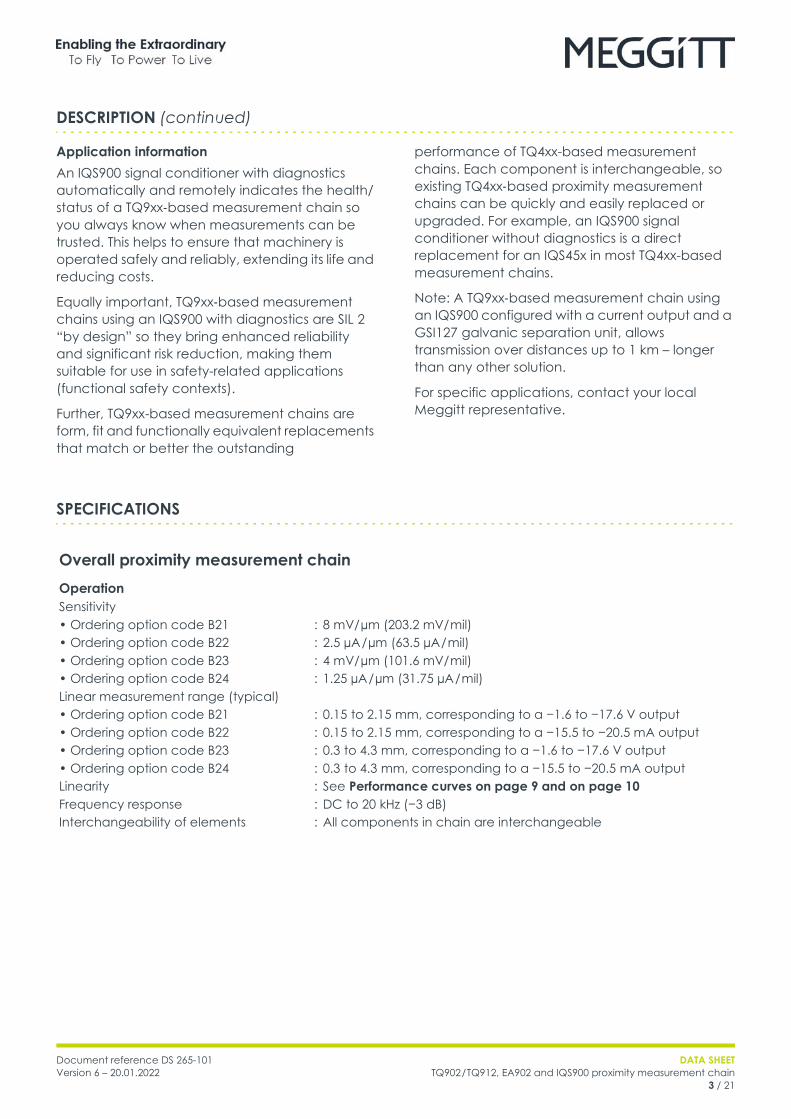
EnvironmentalPotentially explosive atmospheresAvailable in Ex approved versions for use in hazardous areas (ordering option code A5)
Protectionmode TQ9xx EA90x IQS9xx
Europe
ec(Gas)
II 3 G (Zone 2)Ex ec IIC T6… T3 GcLCIE 21 ATEX 1004 XT6: For −40°C ≤ Tamb ≤ +75°CT5: For −40°C ≤ Tamb ≤ +90°CT4: For −40°C ≤ Tamb ≤ +125°CT3: For −40°C ≤ Tamb ≤ +180°C
Suitable for Zones 0, 1, 2 * II 3 G (Zone 2)Ex ec IIC T6 or T5 GcLCIE 21 ATEX 1004 XT6: For −40°C ≤ Tamb ≤ +70°CT5: For −40°C ≤ Tamb ≤ +85°C
ia(Gas)
Suitable for Zones 0, 1, 2.Simple apparatus *.
Suitable for Zones 0, 1, 2 * II 1 G (Zones 0, 1, 2)Ex ia IIC T6 or T5 GaLCIE 21 ATEX 3002 XT6: For −40°C ≤ Tamb ≤ +70°CT5: For −40°C ≤ Tamb ≤ +85°C
ia(Dust)
Suitable for Zones 20, 21, 22.Simple apparatus *.
Suitable for Zones 20, 21, 22 * II 1 D (Zones 20, 21, 22)Ex ia IIIC T200 80°C… T200 115°C DaLCIE 21 ATEX 3002 XT200 80°C: For −40°C ≤ Tamb ≤ +50°CT200 95°C: For −40°C ≤ Tamb ≤ +65°CT200 115°C: For −40°C ≤ Tamb ≤ +85°C
* Means that the product is not required to be certified. Meggitt SA assumes respect of the Ex standards for these components when connected to an Ex certified IQS9xx.
International
ec(Gas)
Ex ec IIC T6… T3 GcIECEx LCIE 21.0005XT6: For −40°C ≤ Tamb ≤ +75°CT5: For −40°C ≤ Tamb ≤ +90°CT4: For −40°C ≤ Tamb ≤ +125°CT3: For −40°C ≤ Tamb ≤ +180°C
Suitable for Zones 0, 1, 2 * Ex ec IIC T6 or T5 GcIECEx LCIE 21.0005XT6: For −40°C ≤ Tamb ≤ +70°CT5: For −40°C ≤ Tamb ≤ +85°C
ia(Gas)
Suitable for Zones 0, 1, 2.Simple apparatus *.
Suitable for Zones 0, 1, 2 * Ex ia IIC T6 or T5 GaIECEx LCIE 21.0006XT6: For −40°C ≤ Tamb ≤ +70°CT5: For −40°C ≤ Tamb ≤ +85°C
ia(Dust)
Suitable for Zones 20, 21, 22.Simple apparatus *.
Suitable for Zones 20, 21, 22 * Ex ia IIIC T200 80°C… T200 115°C DaIECEx LCIE 21.0006XT200 80°C: For −40°C ≤ Tamb ≤ +50°CT200 95°C: For −40°C ≤ Tamb ≤ +65°CT200 115°C: For −40°C ≤ Tamb ≤ +85°C
* Means that the product is not required to be certified. Meggitt SA assumes respect of the Ex standards for these components when connected to an Ex certified IQS9xx.
Document reference DS 265-101Version 6 – 20.01.2022
DATA SHEETTQ902 / TQ912, EA902 and IQS900 proximity measurement chain
5 / 21
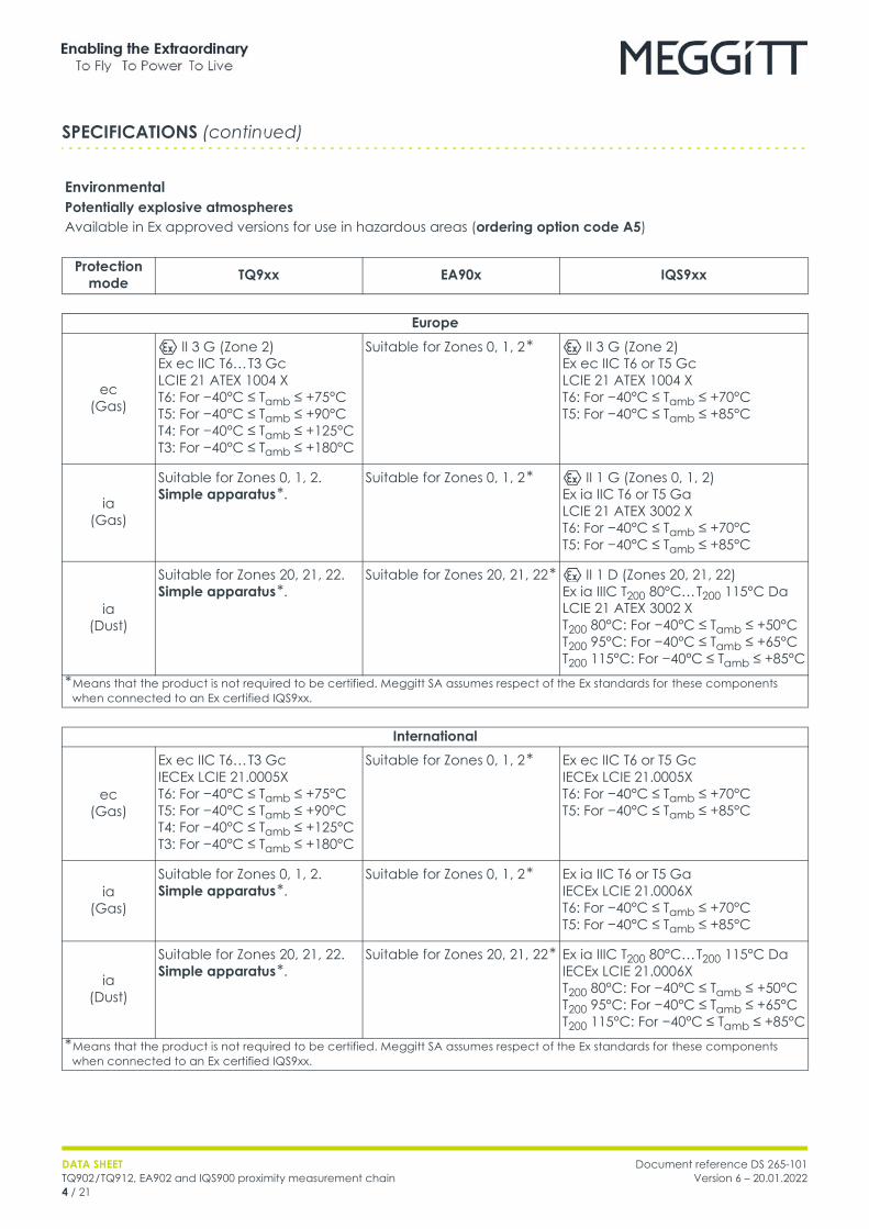
Protectionmode TQ9xx EA90x IQS9xx
North America
ec(Gas)
Class I, Division 2, Groups A, B, C, D T6… T3Ex ec IIC T6… T3 GcClass I, Zone 2, AEx ec IIC T6… T3 GcCCSAUS 80084516
Suitable for Zones 0, 1, 2 * Class I, Division 2, Groups A, B, C, D T6… T5Ex ec IIC T6… T5 GcClass I, Zone 2, AEx ec IIC T6… T5 GcCCSAUS 80084516
ia(Gas)
Suitable for Zones 0, 1, 2.Simple apparatus *.
Suitable for Zones 0, 1, 2 * IS Class I, Division 1, Groups A, B, C, D T6 or T5Ex ia IIC T6 or T5 GaClass I, Zone 0, AEx ia IIC T6 or T5 GaCCSAUS 80084516
ia(Dust)
Suitable for Zones 20, 21, 22.Simple apparatus *.
Suitable for Zones 20, 21, 22 * Class II, Division 1, Groups E, F, G T80°C… T115°CEx ia IIIC T80°C… T115°C DaZone 20, AEx ia IIIC T80°C… T115°C DaCCSAUS 80084516
* Means that the product is not required to be certified. Meggitt SA assumes respect of the Ex standards for these components when connected to an Ex certified IQS9xx.
South Korea
ec(Gas)
Ex ec IIC T6… T3 GcKGS 21-GA4BO-0354XT6: For −40°C ≤ Tamb ≤ +75°CT5: For −40°C ≤ Tamb ≤ +90°CT4: For −40°C ≤ Tamb ≤ +125°CT3: For −40°C ≤ Tamb ≤ +180°C
Suitable for Zones 0, 1, 2 * Ex ec IIC T6… T5 GcKGS 21-GA4BO-0355XT6: For −40°C ≤ Tamb ≤ +70°CT5: For −40°C ≤ Tamb ≤ +85°C
ia(Gas)
Suitable for Zones 0, 1, 2.Simple apparatus *.
Suitable for Zones 0, 1, 2 * Ex ia IIC T6 or T5 GaKGS 21-GA4BO-0353XT6: For −40°C ≤ Tamb ≤ +70°CT5: For −40°C ≤ Tamb ≤ +85°C
ia(Dust)
Suitable for Zones 20, 21, 22.Simple apparatus *.
Suitable for Zones 20, 21, 22 * Ex ia IIIC T200 80°C… T200 115°C DaKGS 21-GA4BO-0352XT200 80°C: For −40°C ≤ Tamb ≤ +50°CT200 95°C: For −40°C ≤ Tamb ≤ +65°CT200 115°C: For −40°C ≤ Tamb ≤ +85°C
* Means that the product is not required to be certified. Meggitt SA assumes respect of the Ex standards for these components when connected to an Ex certified IQS9xx.
SPECIFICATIONS (continued)

DATA SHEETTQ902 / TQ912, EA902 and IQS900 proximity measurement chain6 / 21
Document reference DS 265-101Version 6 – 20.01.2022
Protectionmode TQ9xx EA90x IQS9xx
United Kingdom **
ec(Gas)
II 3 G (Zone 2)Ex ec IIC T6… T3 GcCML 21 UKEX 4549 XT6: For −40°C ≤ Tamb ≤ +75°CT5: For −40°C ≤ Tamb ≤ +90°CT4: For −40°C ≤ Tamb ≤ +125°CT3: For −40°C ≤ Tamb ≤ +180°C
Suitable for Zones 0, 1, 2 * II 3 G (Zone 2)Ex ec IIC T6 or T5 GcCML 21 UKEX 4549 XT6: For −40°C ≤ Tamb ≤ +70°CT5: For −40°C ≤ Tamb ≤ +85°C
ia(Gas)
Suitable for Zones 0, 1, 2.Simple apparatus *.
Suitable for Zones 0, 1, 2 * II 1 G (Zones 0, 1, 2)Ex ia IIC T6 or T5 GaCML 21 UKEX 2548 XT6: For −40°C ≤ Tamb ≤ +70°CT5: For −40°C ≤ Tamb ≤ +85°C
ia(Dust)
Suitable for Zones 20, 21, 22.Simple apparatus *.
Suitable for Zones 20, 21, 22 * II 1 D (Zones 20, 21, 22)Ex ia IIIC T200 80°C… T200 115°C DaCML 21 UKEX 2548 XT200 80°C: For −40°C ≤ Tamb ≤ +50°CT200 95°C: For −40°C ≤ Tamb ≤ +65°CT200 115°C: For −40°C ≤ Tamb ≤ +85°C
* Means that the product is not required to be certified. Meggitt SA assumes respect of the Ex standards for these components when connected to an Ex certified IQS9xx.** Not engraved/marked on the products.
Russian Federation
ec(Gas)
2Ex e IIC T6… T3 Gc XEAЭC RU C-CH.AД07.B.03744/21T6: For −40°C ≤ Tamb ≤ +75°CT5: For −40°C ≤ Tamb ≤ +90°CT4: For −40°C ≤ Tamb ≤ +125°CT3: For −40°C ≤ Tamb ≤ +180°C
Suitable for Zones 0, 1, 2 * 2Ex e IIC T6… T5 Gc XEAЭC RU C-CH.AД07.B.03744/21T6: For −40°C ≤ Tamb ≤ +70°CT5: For −40°C ≤ Tamb ≤ +85°C
ia(Gas)
Suitable for Zones 0, 1, 2.Simple apparatus *.
Suitable for Zones 0, 1, 2 * 0Ex ia IIC T6… T5 Ga XEAЭC RU C-CH.AД07.B.03744/21T6: For −40°C ≤ Tamb ≤ +70°CT5: For −40°C ≤ Tamb ≤ +85°C
ia(Dust)
Suitable for Zones 20, 21, 22.Simple apparatus *.
Suitable for Zones 20, 21, 22 * Ex ia IIIC T200 80°C… T200 115°C Da XEAЭC RU C-CH.AД07.B.03744/21T200 80°C: For −40°C ≤ Tamb ≤ +50°CT200 95°C: For −40°C ≤ Tamb ≤ +65°CT200 115°C: For −40°C ≤ Tamb ≤ +85°C
* Means that the product is not required to be certified. Meggitt SA assumes respect of the Ex standards for these components when connected to an Ex certified IQS9xx.
SPECIFICATIONS (continued)

Document reference DS 265-101Version 6 – 20.01.2022
DATA SHEETTQ902 / TQ912, EA902 and IQS900 proximity measurement chain
7 / 21
For specific parameters of the mode of protection concerned and special conditions for safe use, refer to the Ex certificates that are available from Meggitt SA.
For an IQS9xx signal conditioner with protection mode “Ex ec” located in an Ex Zone 2, the user must ensure that the IQS9xx is installed in an industrial housing or enclosure that ensures a protection rating of at least IP54 (or equivalent).
For the most recent information on the Ex certifications that are applicable to this product, refer to the Ex product register (PL-1511) document that is available from Meggitt SA.
ApprovalsConformity : European Union (EU) declaration of conformity (CE marking).
EAC marking, Eurasian Customs Union (EACU) certificate/declaration of conformity
Electromagnetic compatibility(EMC)
: EN 61000-6-2:2005.EN 61000-6-4:2007 + A1:2011.EN 61326-1:2013.EN 61326-3-2:2008 (SIL).
Electrical safety : EN/IEC 61010-1:2010.CAN/CSA C22.2 61010-1-12 / UL 61010-1:2012.
Environmental management : RoHS compliant (2011/65/EU)Hazardous areas : Ex approved versions
(see Potentially explosive atmospheres on page 4)Functional safety : SIL 2 in accordance with IEC 61508-1:2010 and IEC 61508-2:2010.
Cat 1 PL c in accordance with ISO 13849-1:2015.Machinery protection systems : API 670 5th edition compliant
OtherIndoor use : Limited to indoor use onlyPollution degree : 2Altitude : 4 000 m (13 100 ft) max.
SPECIFICATIONS (continued)

DATA SHEETTQ902 / TQ912, EA902 and IQS900 proximity measurement chain8 / 21
Document reference DS 265-101Version 6 – 20.01.2022
SPECIFICATIONS (continued)
System (chain) calibrationCalibration temperature : +23 °C ± 5 °CTarget material : VCL 140 steel (1.7225)
Note: For applications using a non-standard or special target material, performance curves can be generated and supplied. Contact Meggitt SA for further information.
Total system (chain) lengthThe total system length (TSL) is the sum of the length of the TQ9xx sensor’s integral cable and the length of the EA90x extension cable. For TQ902 / TQ912, EA902 and IQS900 proximity measurement chains, the supported TSLs are obtained from the following different combinations of cables.Total system (chain) lengths• 1 m : 1.0 m integral cable with no extension cable• 5 m : 0.5 m integral cable + 4.5 m extension cable.
1.0 m integral cable + 4.0 m extension cable.1.5 m integral cable + 3.5 m extension cable.2.0 m integral cable + 3.0 m extension cable.5.0 m integral cable with no extension cable.
• 10 m : 0.5 m integral cable + 9.5 m extension cable.1.0 m integral cable + 9.0 m extension cable.1.5 m integral cable + 8.5 m extension cable.2.0 m integral cable + 8.0 m extension cable.5.0 m integral cable + 5.0 m extension cable.10.0 m integral cable with no extension cable.
Note: The combination of cables selected for a particular total system (chain) length depends on the application. For example, to obtain the optimum location for the separation between the integral and extension cables or to eliminate the requirement for an extension cable.
Total system (chain) length trimmingDue to the characteristics of the coaxial cable, an "electrical trimming" of the nominal length of extension cables is necessary to optimize the system performance and the sensor interchangeability.TSL for a 1 m measurement chain : 0.9 m min.TSL for a 5 m measurement chain : 4.4 m min.TSL for a 10 m measurement chain : 8.8 m min.
In-situ test supportRaw output : The raw output (RAW/ COM) provides a “raw” voltage output
signal that corresponds to the internal signals of the IQS900 signal conditioner, even if the IQS900 is configured with a current output.This allows the measurement chain/system operation from sensor to signal conditioner to be easily verified in situ.
Test input : The test input (TEST/ COM) allows a voltage input signal to be injected at the input to the IQS900 signal conditioner in order to test the IQS900 itself and/or cabling to the monitoring system.This allows the measurement chain/system operation from signal conditioner to monitoring system to be easily verified in situ.
Note: See Connectors on page 13 and refer to the Proximity measurement chains using TQ9xx proximity sensors installation manual for further information
Document reference DS 265-101Version 6 – 20.01.2022
DATA SHEETTQ902 / TQ912, EA902 and IQS900 proximity measurement chain
9 / 21
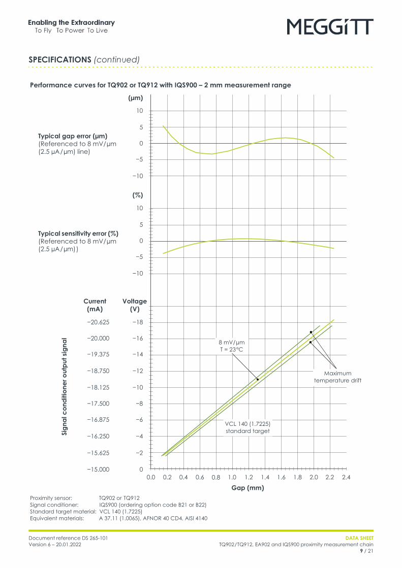
Performance curves for TQ902 or TQ912 with IQS900 – 2 mm measurement range
Proximity sensor: TQ902 or TQ912Signal conditioner: IQS900 (ordering option code B21 or B22)Standard target material: VCL 140 (1.7225)Equivalent materials: A 37.11 (1.0065), AFNOR 40 CD4, AISI 4140
SPECIFICATIONS (continued)
(%)
(µm)
Typical sensitivity error (%) (Referenced to 8 mV/ µm (2.5 µA / µm) )
Typical gap error (µm) (Referenced to 8 mV/ µm (2.5 µA / µm) line)
Gap (mm)
−10
−5
0
5
10
−10
−5
0
5
10
Sign
al c
ondi
tione
r out
put s
igna
l
−12
−14
−16
−18
Voltage(V)
−4
−6
−8
−10
−2
0
−18.750
−19.375
−20.000
−20.625
Current(mA)
−16.250
−16.875
−17.500
−18.125
−15.625
−15.0000.0 0.2 0.4 0.6 0.8 1.0 1.2 1.4 1.6 1.8 2.0 2.2 2.4
Maximum temperature drift
8 mV/ µmT = 23 °C
VCL 140 (1.7225)standard target

DATA SHEETTQ902 / TQ912, EA902 and IQS900 proximity measurement chain10 / 21
Document reference DS 265-101Version 6 – 20.01.2022
Performance curves for TQ902 or TQ912 with IQS900 – 4 mm measurement range
Proximity sensor: TQ902 or TQ912Signal conditioner: IQS900 (ordering option code B23 or B24)Standard target material: VCL 140 (1.7225)Equivalent materials: A 37.11 (1.0065), AFNOR 40 CD4, AISI 4140
SPECIFICATIONS (continued)
(%)
(µm)
−12
−14
−16
−18
−4
−6
−8
−10
−2
0
−18.750
−19.375
−20.000
−20.625
−16.250
−16.875
−17.500
−18.125
−15.625
−15.000
Typical sensitivity error (%) (Referenced to 4 mV/ µm (1.25 µA/ µm) )
Typical gap error (µm) (Referenced to 4 mV/ µm (1.25 µA/ µm) line)
Gap (mm)
−10
−5
0
5
10
−50
−25
0
25
50
Sign
al c
ondi
tione
r out
put s
igna
l
Voltage(V)
Current(mA)
0.0 0.4 0.8 1.2 1.6 2.0 2.4 2.8 3.2 3.6 4.0 4.4 4.8
Maximum temperature drift
4 mV/ µmT = 23 °C
VCL 140 (1.7225)standard target

Document reference DS 265-101Version 6 – 20.01.2022
DATA SHEETTQ902 / TQ912, EA902 and IQS900 proximity measurement chain
11 / 21
TQ902 and TQ912 proximity sensors and EA902 extension cableGeneralSensor input requirements : High-frequency power source from an IQS900 signal conditioner
EnvironmentalTemperature range• Sensor : −40 to 180 °C (−40 to 356 °F) operating.
180 to 220 °C (356 to 428 °F) short-term survival for 2 hours max.• Sensor and cabling : Temperature for use in an Ex Zone: see Potentially explosive
atmospheres on page 4• Cabling, connector and optional
protection: −40 to 200 °C (−40 to 392 °F)
Measurement drift• Sensor and cabling with a total
system (chain) length of 1, 5 or 10 m: < 5 % for −30 to 150 °C (−22 to 302 °F)
Pressure• Sensor : 6 bar (100 psid) between sensor tip and body
Humidity• Sensor and integral cable assembly : 0 to 95 %, non-condensing.
100 % max., condensing (not submerged).
Protection rating (according to IEC 60529)
: The head of the sensor (sensor tip and integral cable) is rated IP68
Vibration (according to IEC 60068-2-26)
: 5 g peak between 10 and 500 Hz
Shock acceleration (according to IEC 60068-2-27)
: 15 g peak (half sine-wave, 11 ms duration)
Physical characteristicsSensor construction : Wire coil Ø 8 mm, PPS (polyphenylene sulfide) high-performance
thermoplastic tip, crimped to a stainless-steel body (AISI 316L)Integral and extension cables : FEP covered 70 Ω coaxial cable, Ø 3.6 mmConnectors : Self-locking miniature coaxial connectors.
Note: When connecting, these should be hand-tightened until locked.
Optional protection• Flexible stainless-steel hose
(protection tube) with FEP sheath (extruded fluorinated ethylene propylene)
: The combination of stainless-steel hose with FEP sheath provides sealed (leak-tight) mechanical and electrically insulated protection.Note: The FEP sheath also provides resistance to almost all chemicals and low permeability to liquids, gases and moisture, while being flexible, low friction and mechanically tough.
SPECIFICATIONS (continued)

DATA SHEETTQ902 / TQ912, EA902 and IQS900 proximity measurement chain12 / 21
Document reference DS 265-101Version 6 – 20.01.2022
IQS900 signal conditionerCurrent output (2-wire signal transmission)Current at min. / max. gap : −15.5 mA / −20.5 mAMeasurement range : 5 mA (corresponding to 2 or 4 mm)Output sensitivity : See Operation on page 3 and IQS900 signal conditioner on
page 18Nominal output signal• Without diagnostics : −15.5 to −20.5 mA• With diagnostics : −15.5 to −20.5 mA indicates normal operation.
Other current values (> −15.5 or < −20.5 mA) indicate a problem with the measurement chain (sensor, cabling and/or signal conditioner).
Output impedance : > 60 kΩ.Note: Recommended monitoring system input impedance: ≤ 350 Ω.
Voltage output (3-wire signal transmission)Voltage at min. / max. gap : −1.6 V / −17.6 VMeasurement range : 16 V (corresponding to 2 or 4 mm)Output sensitivity : See Operation on page 3 and IQS900 signal conditioner on
page 18Nominal output signal• Without diagnostics : −1.6 t o −17.6 V• With diagnostics : −1.6 t o −17.6 V indicates normal operation.
Other voltage values (> −1.6 or < −17.6 V) indicate a problem with the measurement chain (sensor, cabling and/or signal conditioner).
Output impedance(small signal)
: < 100 Ω at DC.< 300 Ω at 20 kHz.Note: Recommended monitoring system input impedance: ≥ 50 kΩ.The low output impedance enables operation with a wider range of galvanic separation units / safety barriers, without loss of performance. For example, an IQS900 (output impedance 100 Ω) connected to a third-party galvanic isolator (input impedance 10 kΩ) will see 1% max. signal loss due to impedance matching.
Protection : Short-circuit (35 mA), overvoltage (−33 VDC typical)Output voltage swing : −0.05 to −22.5 V with a 50 kΩ load and a −24 VDC power supply.
−0.05 to −21.5 V with a 10 kΩ load and a −24 VDC power supply.
Raw output (RAW/COM)Output voltage range : −0.8 to −8.8 V (nominal)Output impedance : < 15 kΩ up to 20 kHz.
< 10 kΩ for DC measurement. Note: Recommended test equipment input impedance: >1 MΩ.
Protection : Short-circuit, overvoltage (−33 VDC typical)
Test input (TEST/COM)Input voltage range : ± 0.1 to 4.0 VPK-PK (nominal), depending on the measured gap (DC)Input impedance : 500 kΩ.
Note: Recommended test equipment output impedance: > 5 kΩ.Protection : Overvoltage (−33 VDC typical)
SPECIFICATIONS (continued)

Document reference DS 265-101Version 6 – 20.01.2022
DATA SHEETTQ902 / TQ912, EA902 and IQS900 proximity measurement chain
13 / 21
Power supply (to IQS900)Input voltage range• With a current output signal
(2-wire signal transmission): −18 to −30 VDC (nominal)
• With a voltage output signal (3-wire signal transmission)
: −19 to −30 VDC (nominal)
Current consumption (with nominal 24 VDC supply)
: 25 mA max.
Overvoltage protection (diode) : −33 VDC typical
Note: The IQS900 should be powered (energised) using a limited-power, low-voltage power supply such as a sensor power supply output provided a VM600 or VibroSmart ® monitoring and/or protection system, a GSI127 galvanic separation unit or other suitable power supply.In safety-related applications, an IQS900 must be powered using a limited-power, low-voltage power supply with a safe limitation of −30 VDC (nominal), even in the event of a single fault with the power supply.
EnvironmentalTemperature• Operating and storage : −40 to 85 °C (−40 to 185 °F)Humidity : 0 to 95 %, non-condensing
Protection rating(according to IEC 60529)
: IP20.Note: The IQS900 is suitable for indoor use only unless it is installed in an industrial housing or enclosure that ensures a higher level of environmental protection.
Flammability : UL94 V-0
Vibration (according to IEC 60068-2-6)
: 5 g peak between 10 and 500 Hz
Shock acceleration(according to IEC 60068-2-27)
: 15 g peak (half sine-wave, 11 ms duration)
ConnectorsSelf-locking miniature coaxial connector (bidirectional)
: 1 contact for sensor-side signal: sensor (connects to TQ9xx sensor or EA902 cable)
Screw-terminal connector (input) : 4 contacts for test signals: raw output (RAW/ COM) and test input (TEST/ COM)
Screw-terminal connector (output) : 4 contacts for monitor-side signals: measurement output (O/P / COM) and power supply input (−24V/ COM)
Screw-terminal connectors• Clamping range (min. to max.) : 0.2 to 1.5 mm2 (24 to 16 AWG)• Tightening torque (min. to max.) : 0.2 to 0.25 N•m (0.15 to 0.18 lb-ft)
Note: The IQS900 features removal screw-terminal connectors that can unplugged from the main body of its housing to simplify installation and mounting.
SPECIFICATIONS (continued)
DATA SHEETTQ902 / TQ912, EA902 and IQS900 proximity measurement chain14 / 21
Document reference DS 265-101Version 6 – 20.01.2022
Physical characteristicsElectrical connections : Self-locking miniature coaxial connector and removable screw-
terminal connectors (see Connectors on page 13)Housing material : Injection-moulded aluminium, paintedDimensions : See Mechanical drawings and ordering information on page 18 Weight : 200 g (0.44 lb) approx.Mounting• Without DIN-rail mounting adaptor : Two M4 screws• With DIN-rail mounting adaptor
(ordering option code I1): MA130 DIN-rail mounting adaptor for IPC707 and IQS900
signal conditioners.Suitable for TH 35 DIN rails (according to EN 50022 / IEC 60715). For example, TH 35-7.5 or TH 35-15. See Accessories on page 19.
SPECIFICATIONS (continued)
Document reference DS 265-101Version 6 – 20.01.2022
DATA SHEETTQ902 / TQ912, EA902 and IQS900 proximity measurement chain
15 / 21
MECHANICAL DRAWINGS AND ORDERING INFORMATION
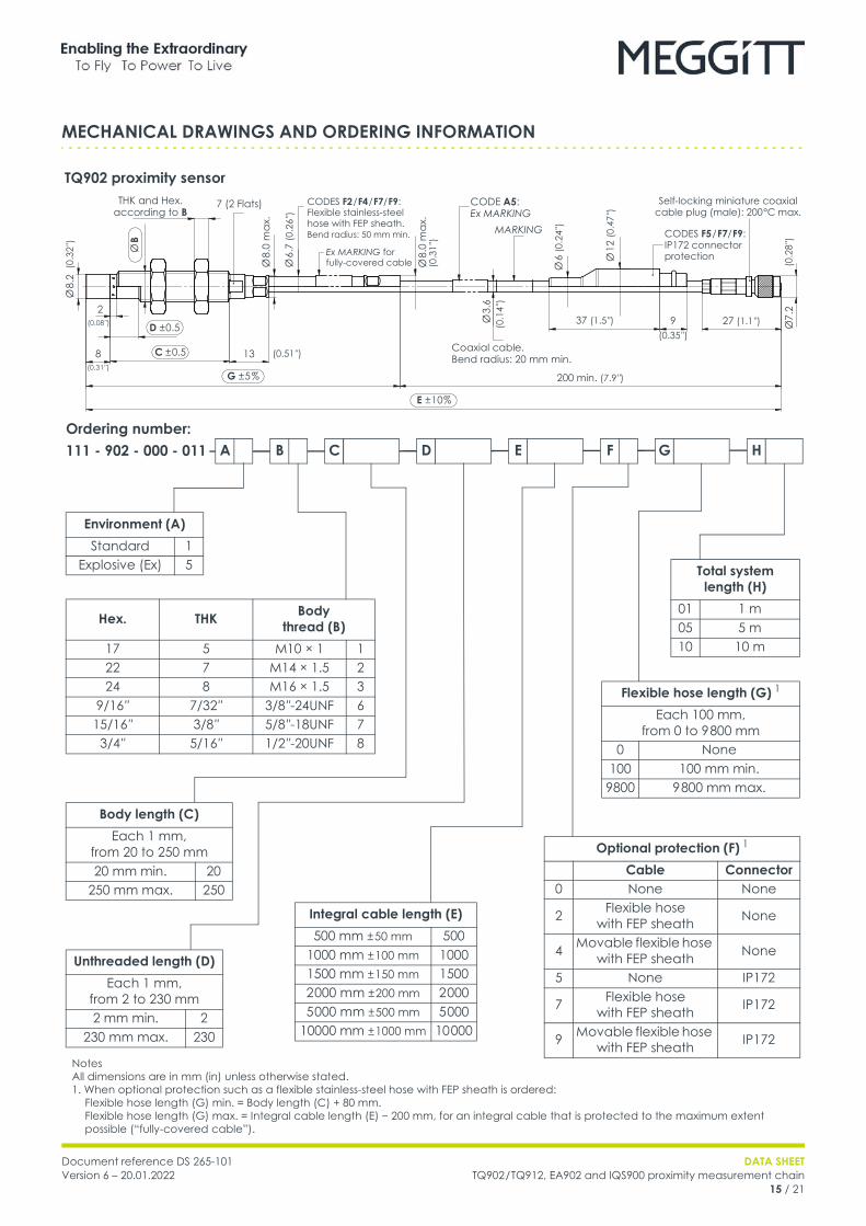
TQ902 proximity sensor
Flexible hose length (G) 1
Each 100 mm,from 0 to 9 800 mm
0 None100 100 mm min.
9800 9 800 mm max.
A B C GED F H
Total system length (H)
01 1 m05 5 m10 10 m
Hex. THK Bodythread (B)
17 5 M10 × 1 122 7 M14 × 1.5 224 8 M16 × 1.5 3
9/16 ″ 7/32 ″ 3/8 ″-24UNF 615/16 ″ 3/8 ″ 5/8 ″-18UNF 73/4 ″ 5/16 ″ 1/2 ″-20UNF 8
Ordering number: 111 - 902 - 000 - 011
Environment (A)Standard 1
Explosive (Ex) 5
Optional protection (F) 1
Cable Connector0 None None
2 Flexible hosewith FEP sheath None
4 Movable flexible hose with FEP sheath None
5 None IP172
7 Flexible hosewith FEP sheath IP172
9 Movable flexible hose with FEP sheath IP172
Body length (C)Each 1 mm,
from 20 to 250 mm20 mm min. 20
250 mm max. 250
Unthreaded length (D)Each 1 mm,
from 2 to 230 mm2 mm min. 2
230 mm max. 230
Integral cable length (E)500 mm ± 50 mm 500
1000 mm ± 100 mm 10001500 mm ± 150 mm 15002 000 mm ± 200 mm 2 0005 000 mm ± 500 mm 5 000
10000 mm ± 1000 mm 10 000
NotesAll dimensions are in mm (in) unless otherwise stated.1. When optional protection such as a flexible stainless-steel hose with FEP sheath is ordered: Flexible hose length (G) min. = Body length (C) + 80 mm. Flexible hose length (G) max. = Integral cable length (E) − 200 mm, for an integral cable that is protected to the maximum extent possible (“fully-covered cable”).
CODES F2 / F4 / F7/ F9:Flexible stainless-steel hose with FEP sheath. Bend radius: 50 mm min.
Coaxial cable.Bend radius: 20 mm min.
Self-locking miniature coaxialcable plug (male): 200 °C max.
Ø 8.
2
37 (1.5 ″) 9 27 (1.1 ″)D ± 0.5
CODES F5 / F7/ F9:IP172 connector protection
7 (2 Flats)
2
MARKING
CODE A5: Ex MARKING
200 min. (7.9 ″)
138
Ø 8.
0 m
ax.
Ø7.
2
THK and Hex. according to B
Ø B
C ± 0.5
G ± 5 %
Ø 6.
7 (0
.26 ″
)
Ex MARKING for fully-covered cable
E ± 10 %
Ø 8.
0 m
ax.
Ø 6
(0.2
4 ″)
Ø 12
(0.4
7 ″)
Ø 3.
6
(0.08 ″)
(0.31 ″)
(0.3
2 ″)
(0.51 ″)
(0.3
1 ″)
(0.1
4 ″)
(0.35 ″)
(0.2
8 ″)
DATA SHEETTQ902 / TQ912, EA902 and IQS900 proximity measurement chain16 / 21
Document reference DS 265-101Version 6 – 20.01.2022
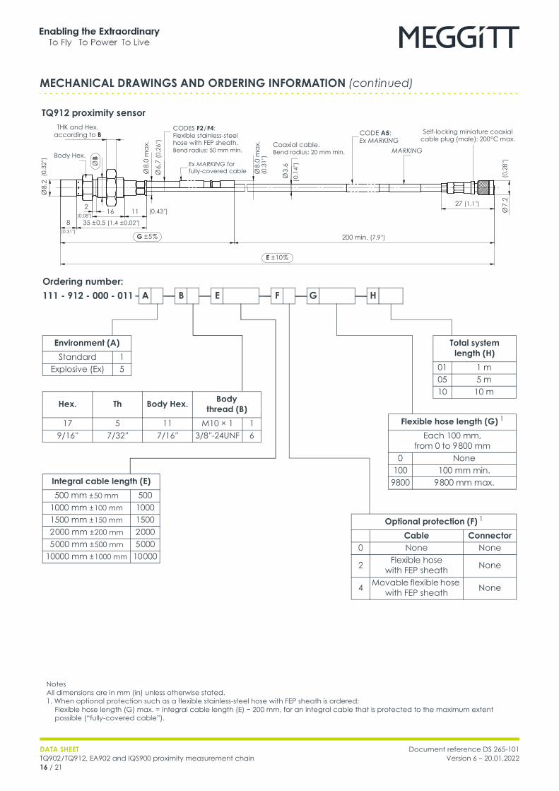
TQ912 proximity sensor
MECHANICAL DRAWINGS AND ORDERING INFORMATION (continued)
GE F H
Flexible hose length (G) 1
Each 100 mm,from 0 to 9 800 mm
0 None100 100 mm min.
9800 9 800 mm max.
A B
Total system length (H)
01 1 m05 5 m10 10 m
Hex. Th Body Hex. Bodythread (B)
17 5 11 M10 × 1 19/16 ″ 7/32 ″ 7/16 ″ 3/8 ″-24UNF 6
Ordering number: 111 - 912 - 000 - 011
Environment (A)Standard 1
Explosive (Ex) 5
Optional protection (F) 1
Cable Connector0 None None
2 Flexible hosewith FEP sheath None
4 Movable flexible hose with FEP sheath None
Integral cable length (E)500 mm ± 50 mm 500
1000 mm ± 100 mm 10001500 mm ± 150 mm 15002 000 mm ± 200 mm 2 0005 000 mm ± 500 mm 5 000
10000 mm ± 1000 mm 10 000
Self-locking miniature coaxialcable plug (male): 200 °C max.
Ø 8.
2
27 (1.1 ″)2
200 min. (7.9 ″)
8
Ø 7.
2
1635 ± 0.5 (1.4 ± 0.02″)
11
NotesAll dimensions are in mm (in) unless otherwise stated.1. When optional protection such as a flexible stainless-steel hose with FEP sheath is ordered: Flexible hose length (G) max. = Integral cable length (E) − 200 mm, for an integral cable that is protected to the maximum extent possible (“fully-covered cable”).
E ± 10 %
G ± 5 %
Body Hex.
Ø B
Ø 8.
0 m
ax.
Ø 6.
7 (0
.26 ″
)
CODES F2 / F4:Flexible stainless-steel hose with FEP sheath. Bend radius: 50 mm min.
Ex MARKING for fully-covered cable
THK and Hex. according to B
Ø 8.
0 m
ax. Coaxial cable.
Bend radius: 20 mm min.
Ø 3.
6
CODE A5: Ex MARKING
MARKING
(0.3
2 ″)
(0.31 ″)
(0.08 ″)(0.43 ″)
(0.3
1 ″)
( 0.1
4 ″)
(0.2
8 ″)

Document reference DS 265-101Version 6 – 20.01.2022
DATA SHEETTQ902 / TQ912, EA902 and IQS900 proximity measurement chain
17 / 21
EA902 extension cable
MECHANICAL DRAWINGS AND ORDERING INFORMATION (continued)
47 (1.9 ″)
GE F
Flexible hose length (G) 2
Each 100 mm,from 0 to 9 300 mm.
0 None100 100 mm min.
9300 9 300 mm max.
AOrdering number: 913 - 902 - 000 - 011
Environment (A)Standard 1
Explosive (Ex) 5
CODES F2 / F7:Flexible stainless-steel hose with FEP sheath. Bend radius: 50 mm min.
FEP coaxial cable.Bend radius: 20 mm min.
Self-locking miniature coaxial cable plug (male): 200 °C max.
Ø 7.
2
G ± 5 %
CODES F5 / F7:IP172 connector protection
MARKING
CODE A5: Ex MARKING
200 min. (7.9 ″)
NotesAll dimensions are in mm (in) unless otherwise stated.1. The total system (chain) length = TQ902 or TQ912 integral cable length + EA902 extension cable length (E). For information on combining integral and extension cables to obtain a particular total system (chain) length, see Total system (chain) length on page 8. For information on cable length tolerances, see Total system (chain) length trimming on page 8.2. When optional protection such as a flexible stainless-steel hose with FEP sheath is ordered: Flexible hose length (G) max. = EA902 extension cable length (E) − 200 mm, for an extension cable that is protected to the maximum extent possible (“fully-covered cable”).
Extension cable length (E) 1
3 000 mm ± 300 mm 3 0003 500 mm ± 350 mm 3 5004 000 mm ± 400 mm 4 0004 500 mm ± 450 mm 4 5005 000 mm ± 500 mm 5 0008 000 mm ± 800 mm 8 0008 500 mm ± 850 mm 8 5009 000 mm ± 900 mm 9 0009 500 mm ± 950 mm 9 500
Optional protection (F) 2
Cable Connector0 None None
2 Flexible hosewith FEP sheath None
5 None IP172
7 Flexible hosewith FEP sheath IP172
Ø 3.
6
Self-locking miniature coaxial cable plug (female): 200 °C max.
(0.2
8 ″)
(0.2
8 ″)
Ø 7.
2
E ± 10 %
27 (1.1 ″)12(0.47 ″)
12(0.47 ″)
(0.1
4 ″)
Ø 8
ma
x.
Ø 6.
7(0
.26 ″
)
Ø 8
ma
x. (0
.31 ″
)
Ex MARKING forfully-covered cable
Ø 6
(0.2
4 ″)
Ø 12
ma
x.(0
.47 ″
)
28 (1.1 ″)

DATA SHEETTQ902 / TQ912, EA902 and IQS900 proximity measurement chain18 / 21
Document reference DS 265-101Version 6 – 20.01.2022
IQS900 signal conditioner
MECHANICAL DRAWINGS AND ORDERING INFORMATION (continued)
Installation (I)Without DIN-rail
adaptor 0
With DIN-rail adaptor (MA130) 1
Total system length (H)1 m 015 m 0510 m 10
Side and top views
MARKING
Note: All dimensions in mm (in) unless otherwise
stated.
MARKING
35.5
(1.4
″)
23(0
.91″
)
5(0
.20 ″
)
70 (2.8 ″)
45 (1
.8 ″)
79.4 (3.1″)
54 (2
.1″)
13(0
.51 ″
)
35 (1.4 ″)
MARKING
35 (1.4 ″)
40.5
(1.6
″)
Ø 4.82(0.19 ″)
Side and end views with DIN-rail mounting adaptor (ordering option code I1)
IQS900 mounted on MA130 DIN-rail adaptor
A BOrdering number: 204 - 900 - 000 - 011 H
Environment (A) 1
Standard 1Explosive (Ex) 5
Diagnostics (C) 2
Withoutdiagnostics 1
Withdiagnostics (SIL) 2
Measurement range Sensitivity (B)
2 mm8 mV/ µm 21
2.5 µA / µm 22
4 mm4 mV/ µm 23
1.25 µA / µm 24
C I
NotesSee following page.

Document reference DS 265-101Version 6 – 20.01.2022
DATA SHEETTQ902 / TQ912, EA902 and IQS900 proximity measurement chain
19 / 21
IQS900 signal conditioner (continued)
ACCESSORIES
ABA17x Industrial housings : Refer to corresponding data sheetIP172 Interconnection protection : Refer to corresponding data sheetJB118 Junction box : Refer to corresponding data sheetKS107 Flexible conduit (protection tube) : Refer to corresponding data sheetMA130 Mounting adaptor : See belowPA15x Probe mounting adaptors : Refer to corresponding data sheetsSG1xx Cable feedthroughs : Refer to corresponding data sheets
MECHANICAL DRAWINGS AND ORDERING INFORMATION (continued)
Notes1. Ordering option code A5 (“Ex”) specifies an IQS900 signal conditioner suitable for use for use in hazardous areas. • For an IQS900 signal conditioner with protection mode “Ex” located in an Ex Zone 2, the user must ensure that the IQS900 is installed in an industrial housing or enclosure that ensures a protection rating of at least IP54 (or equivalent).2. Ordering option code C specifies an IQS900 signal conditioner either without diagnostics (C1) or with diagnostics (C2): • An IQS900 signal conditioner without diagnostics (C1) is similar to the IQS45x, which it replaces. The IQS900 is a form, fit and functionally equivalent replacement that matches or betters the measurement specifications of the IQS45x. • An IQS900 signal conditioner with diagnostics (C2) includes optional diagnostic circuitry that automatically detects and remotely indicates problems with the measurement chain (sensor, cabling and/or the IQS900 itself). An IQS900 with diagnostics is certified SIL 2 (IEC 61508) and Cat 1 PL c (ISO 13849) “by design” to more easily meet the requirements of safety-related applications. Contact Meggitt SA for further information.
DATA SHEETTQ902 / TQ912, EA902 and IQS900 proximity measurement chain20 / 21
Document reference DS 265-101Version 6 – 20.01.2022
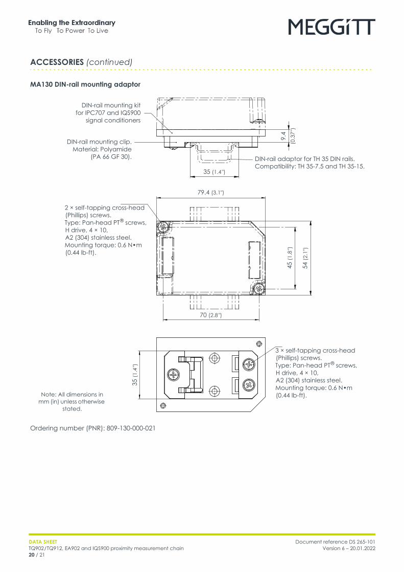
MA130 DIN-rail mounting adaptor
Ordering number (PNR): 809-130-000-021
ACCESSORIES (continued)
DIN-rail adaptor for TH 35 DIN rails.Compatibility: TH 35-7.5 and TH 35-15.
2 × self-tapping cross-head (Phillips) screws.Type: Pan-head PT ® screws, H drive, 4 × 10, A2 (304) stainless steel.Mounting torque: 0.6 N•m (0.44 lb-ft).
DIN-rail mounting clip.Material: Polyamide
(PA 66 GF 30).
35 (1.4 ″)
9.4
(0.3
7 ″)
35 (1
.4 ″)
79.4 (3.1″)
70 (2.8 ″)
45 (1
.8 ″)
54 (2
.1″)
DIN-rail mounting kitfor IPC707 and IQS900
signal conditioners
3 × self-tapping cross-head (Phillips) screws.Type: Pan-head PT ® screws, H drive, 4 × 10, A2 (304) stainless steel.Mounting torque: 0.6 N•m (0.44 lb-ft).Note: All dimensions in
mm (in) unless otherwise stated.

Meggitt (Meggitt PLC) is a leading international engineering company, headquartered in England, that designs and delivers high-performance components and subsystems for aerospace, defence and selected energy markets. Meggitt comprises four customer-aligned divisions: Airframe Systems, Engine Systems, Energy & Equipment and Services & Support.The Energy & Equipment division includes the Energy Sensing and Controls product group that specialises in sensing and monitoring solutions for a broad range of energy infrastructure, and control valves for industrial gas turbines, primarily for the Power Generation, Oil & Gas and Services markets. Energy & Equipment is headquartered in Switzerland (Meggitt SA) and incorporates the vibro-meter ® product line, which has over 65 years of sensor and systems expertise and is trusted by original equipment manufacturers (OEMs) globally.
All information in this document, such as descriptions, specifications, drawings, recommendations and other statements, is believed to be reliable and is stated in good faith as being approximately correct, but is not binding on Meggitt (Meggitt SA) unless expressly agreed in writing. Before acquiring and/or using this product, you must evaluate it and determine if it is suitable for your intended application. You should also check our website at www.meggittsensing.com/energy for any updates to data sheets, certificates, product drawings, user manuals, service bulletins and/or other instructions affecting the product.Unless otherwise expressly agreed in writing with Meggitt SA, you assume all risks and liability associated with use of the product. Any recommendations and advice given without charge, whilst given in good faith, are not binding on Meggitt SA. Meggitt (Meggitt SA) takes no responsibility for any statements related to the product which are not contained in a current Meggitt SA publication, nor for any statements contained in extracts, summaries, translations or any other documents not authored and produced by Meggitt SA.The certifications and warranties applicable to the products supplied by Meggitt SA are valid only for new products purchased directly from Meggitt SA or from an authorised distributor of Meggitt SA.In this publication, a dot (.) is used as the decimal separator and thousands are separated by thin spaces. Example: 12 345.678 90.Copyright © 2022 Meggitt SA. All rights reserved. The information contained in this document is subject to change without prior notice.
Sales offices Local representative Head office
Meggitt has offices in more than 30 countries. For a complete list, please visit our website.
Meggitt SARoute de Moncor 4
Case postale1701 Fribourg
SwitzerlandTel: +41 26 407 11 11
Fax: +41 26 407 13 01 [email protected]
www.meggittsensing.com/energywww.meggitt.com
Document reference DS 265-101Version 6 – 20.01.2022
DATA SHEETTQ902 / TQ912, EA902 and IQS900 proximity measurement chain
21 / 21