Embed Size (px)
Citation preview

TOYOTA 2011+Tacoma TX Package (16” “Beadlock”) ALLOY WHEEL Preparation TRD Technical Support 1-800-688-5912
Page 1 of 15 pages Issue: F 3/04/14
Part Number: PTR18-35090 Black Kit Contents Item # Quantity Reqd. Description 1 1 Cast Al Wheel 16”x7.5”x10mm
Hardware Bag Contents Item # Quantity Reqd. Description 1 1 per wheel TRD Center Cap
P/N PTR18-35092 2 1 per wheel Wheel Lock Ring
P/N PTR18-35091 3 12 per wheel Lock Ring Fasteners &Washers
P/N PTR18-35093 (pkg. of 12)
Additional Items Required For Installation Item # Quantity Reqd. Description 1 1 per wheel
Tacoma ………
Tire: BFG Rugged Trail T/A P265/70R16 111T M+S OE Take-Off (Recommended)
2 1 per vehicle
Tacoma
Lug nut Set w/ Spline Tool & Wheel Locks & Lock Key Tool P/N PTR27-35100
3 0 – 4 as needed
Tacoma Tacoma
TPMS 20 degree angle (For Styled Steel wheel swap) Bulk PPO P/N PTR42-3507B Single DIO P/N 42607-06011
4 As needed Low-Profile, Lead-Free Balance Weights 3M TN-2023 (or equivalent) Stick-on Type and/or Clip-on Type
5 1 PPO DIO
Vinyl Pouch PT276-06999 Vinyl Pouch MDC#00602-06999
Conflicts
Recommended Tools Personal & Vehicle Protection
Notes
Safety Glasses Seat Protection Blanket
Special Tools Notes Tire Changing Machine Hunter or Corghi or equiv. Tire Bead Clip/Depressor Corghi 801262417 or equiv. Wheel Balancing Machine Hunter GSP9700 or equiv. Centering Cone Hunter BACK-SIDE collet
192-169-2 or equiv. Wing Nut Hunter 76-371-3 or equiv. 6” Cup w/ Sleeve Hunter 175-392-1 or equiv. 6” Protector Sleeve Hunter 106-157-2 or equiv. Foot Brake Application Tool Snap-on or equivalent. Toyota Diagnostic Tester or Techstream Device
Software Version 13.2a or newer required.
Tire Pressure Sensor SST 00002-TTPWS or equiv.
Installation Tools Notes Lug Nut Wrench 21 mm wrench flat Torque Wrench 20-150 ft-lbf (27-204 N-m) Torque Wrench 30-150 in-lbf (3.3-17 N-m) Sockets 11mm, and 21 mm
Deep Well, Thin Wall Ratchets Air and or manual Extensions ¼, 3/8, ½ inch as needed TORX Male T30 TORX for lock ring Clean Lint-free Cloth Nylon Panel Removal Tool e.g. Toyota SST # 00002-
06001-01 or equiv.Valve Stem Removal Tool Schraeder Valve Type Valve Stem Torque Tool Snap-On QDTPMS or equiv.Wire Brush Hand held size
Special Chemicals Notes Tire Lube / Paste Myers or equivalent Cleaner (for rework of stick on weights if needed)
PPO/DIO: locally approved cleaner. No stronger than a 50-50 mix of Simple Green and Water.
General Applicability Applicable to 2011+ Tacoma 4X4 and/or PreRunner. Use w tire size P265/70R16 111T M+S
Recommended Sequence of Application Item # Accessory 1 TRD 16” Alloy Wheel & Tire 2
Vehicle Service Parts (May be required for reassembly) Item # Quantity Reqd. Description 1 0 – 4
as needed Valve Stem Grommet Fit Kit (if required) P/N 04423 -0E010
2 0 – 4 as needed
Tacoma 20°TPMS Bulk PPO P/N PTR42-3507B
Legend STOP: Damage to the vehicle may occur. Do not proceed until process has been complied with.
OPERATOR SAFETY: Use caution to avoid risk of injury.
CAUTION: A process that must be carefully observed in order to reduce the risk of damage to the accessory/vehicle and to ensure a quality installation.
TOOLS & EQUIPMENT: Used in Figures calls out the specific tools and equipment recommended for this process.
REVISION MARK: This mark highlights a change in installation with respect to previous issue. SAFETY TORQUE: This mark indicates that torque is related to safety.

TOYOTA 2011+Tacoma TX Package (16” “Beadlock”) ALLOY WHEEL Procedure TRD Technical Support 1-800-688-5912
Page 2 of 15 pages Issue: F 3/04/14
Care must be taken when installing this accessory to ensure damage does not occur to the vehicle. The installation of this accessory should follow approved guidelines to ensure a quality installation. These guidelines can be found in the "Accessory Installation Practices" document. Please see your local dealer for a copy of this document.
1. Vehicle Preparation.
(a) Firmly apply the parking brake.
(b) Put automatic transmission in "P" (Fig. 1-1).
Put manual transmission in “R”.
(c) Add seat protection (blanket) and apply the
foot brake using a foot brake application tool
(Fig. 1-2).
(d) Lift the vehicle.
(e) Mark the tire installation position on the
inward facing tire sidewall. For example,
Front Right = FR, Front Left = FL, Rear Right
= RR, Rear Left = RL.
(f) Later, at Step 4, install the original tires on the
new or refinished wheels with the marked side
facing inwards.
(g) Place the tire/wheel assemblies on the vehicle
in the marked positions. Refer to T-SB-
PG002-05 as needed.
(h) Remove the OE wheel and tire assembly from
the vehicle (Fig. 1-3). Wear safety glasses
while removing wheels.
Fig. 1-3
Fig. 1-2
Foot Brake Application Tool
Fig. 1-1
TOYOTA 2011+Tacoma TX Package (16” “Beadlock”) ALLOY WHEEL Procedure TRD Technical Support 1-800-688-5912
Page 3 of 15 pages Issue: F 3/04/14
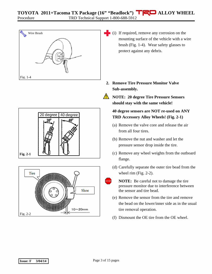
(i) If required, remove any corrosion on the
mounting surface of the vehicle with a wire
brush (Fig. 1-4). Wear safety glasses to
protect against any debris.
2. Remove Tire Pressure Monitor Valve
Sub-assembly.
NOTE: 20 degree Tire Pressure Sensors
should stay with the same vehicle!
40 degree sensors are NOT re-used on ANY
TRD Accessory Alloy Wheels! (Fig. 2-1)
(a) Remove the valve core and release the air
from all four tires.
(b) Remove the nut and washer and let the
pressure sensor drop inside the tire.
(c) Remove any wheel weights from the outboard
flange.
(d) Carefully separate the outer tire bead from the
wheel rim (Fig. 2-2).
NOTE: Be careful not to damage the tire pressure monitor due to interference between the sensor and tire bead.
(e) Remove the sensor from the tire and remove
the bead on the lower/inner side as in the usual
tire removal operation.
(f) Dismount the OE tire from the OE wheel.
Fig. 1-4
Wire Brush
Fig. 2-2
Fig. 2-1

TOYOTA 2011+Tacoma TX Package (16” “Beadlock”) ALLOY WHEEL Procedure TRD Technical Support 1-800-688-5912
Page 4 of 15 pages Issue: F 3/04/14
3. Install Tire Pressure Monitor Sensor (TPMS)
Sub-assembly into TRD Accessory Wheels.
(a) If the previously removed sensor is a 20
degree sensor, proceed to step 3(c). If the
previously removed sensor is a 40 degree
sensor (e.g. Tacoma styled steel wheels), you
must install new 20 degree sensors into
accessory wheels. When installing new 20
degree sensors, you MUST record sensor ID
codes for all four wheels and register these
four new ID codes (Fig. 3-1) with the vehicle
ECU. Each sensor has a unique sensor ID
code. The sensor ID code is a 7 or 8-character
hexadecimal string comprised of numbers 0
through 9 and letters A through F. See Fig. 3-
1 for example code and location.
(b) IMPORTANT! Record all four new TPMS
ID codes onto a sheet of paper or in a shop
notebook. These MUST be programmed into
the vehicle ECU later in Step 10.
(c) Check that the wheel valve hole is clean and
free of sharp edges or burrs.
(d) Visually check that there is no deformation or
damage on the tire pressure monitor valve
sub-assembly. Check that the grommet,
washer, and nut are all clean and in good
condition.
NOTE: Replace the grommet ONLY IF the
grommet is old or was damaged. A damaged
grommet is NOT reusable.
Fig. 3-1
TACOMA & FJ CRUISER

TOYOTA 2011+Tacoma TX Package (16” “Beadlock”) ALLOY WHEEL Procedure TRD Technical Support 1-800-688-5912
Page 5 of 15 pages Issue: F 3/04/14
(e) Insert the tire pressure monitor valve sub-
assembly into the wheel valve hole from the
inside of the rim and bring the valve stem to
the outside (Fig. 3-2).
(f) Insert the tire pressure monitor valve sub-
assembly so that the sensor ID number and
text is visible (Fig. 3-2).
NOTE: Incorrect orientation of the pressure monitor sub-assembly may cause damage and prevent signal transmission during high-speed driving.
(g) Install the washer on the outside of the wheel
and secure with the nut.
Torque the nut to 36 in-lbf (4.0 N-m)
4. Tire Mounting.
IMPORTANT: Mount the tires BEFORE
installing the wheel lock rings!
NOTE: Mount the tires with the raised white
letters facing out on all tires.
(a) Use tire lube on the tire beads and bead
locations on wheel prior to mounting.
(b) Position the wheel on the mounting machine
with the sensor at ~ 7 o'clock position (shaded
area in Fig. 4-1).
(1) The mount/dismount head is considered as
12 o'clock.
(c) Mount the lower tire bead.
NOTE: If the sensor is positioned outside this area, it generates interference with the tire bead, causing possible damage to the sensor.
(d) Re-position the wheel on the mounting
machine with the sensor at ~ 7 o'clock
position (shaded area in Fig. 4-1).
Nut
Rim
Tire
Tire ValveSensor
Grommet (Rubber)
Valve Cap Washer (Metal)
Fig. 3-2
Rim Rotating Direction
Area for the Sensor (60 deg)
12 o’clock Position
Mounting Machine Head
Rim
Fig. 4-1
UPPER AND LOWER BEAD PLACEMENT CLOCKWISE ROTATION
TOYOTA 2011+Tacoma TX Package (16” “Beadlock”) ALLOY WHEEL Procedure TRD Technical Support 1-800-688-5912
Page 6 of 15 pages Issue: F 3/04/14
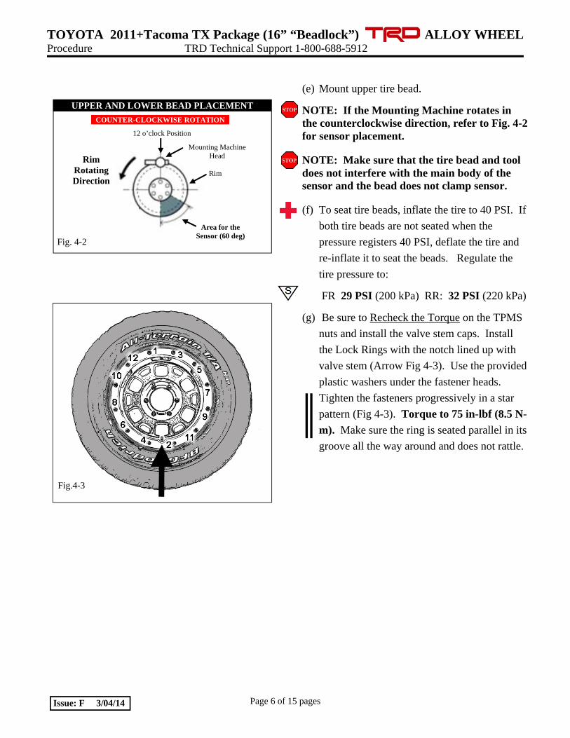
(e) Mount upper tire bead.
NOTE: If the Mounting Machine rotates in the counterclockwise direction, refer to Fig. 4-2 for sensor placement.
NOTE: Make sure that the tire bead and tool does not interfere with the main body of the sensor and the bead does not clamp sensor.
(f) To seat tire beads, inflate the tire to 40 PSI. If
both tire beads are not seated when the
pressure registers 40 PSI, deflate the tire and
re-inflate it to seat the beads. Regulate the
tire pressure to:
FR 29 PSI (200 kPa) RR: 32 PSI (220 kPa)
(g) Be sure to Recheck the Torque on the TPMS
nuts and install the valve stem caps. Install
the Lock Rings with the notch lined up with
valve stem (Arrow Fig 4-3). Use the provided
plastic washers under the fastener heads.
Tighten the fasteners progressively in a star
pattern (Fig 4-3). Torque to 75 in-lbf (8.5 N-
m). Make sure the ring is seated parallel in its
groove all the way around and does not rattle.
UPPER AND LOWER BEAD PLACEMENT
Rim Rotating Direction
Rim
Mounting Machine Head
12 o’clock Position
Area for the Sensor (60 deg)
Fig. 4-2
COUNTER-CLOCKWISE ROTATION
Fig.4-3

TOYOTA 2011+Tacoma TX Package (16” “Beadlock”) ALLOY WHEEL Procedure TRD Technical Support 1-800-688-5912
Page 7 of 15 pages Issue: F 3/04/14
5. Wheel Balancing.
NOTE: Application temperature for stick-on type weight is above 50°F (10°C). Weights should be no taller than 4 ~ 5 mm in height. Remove the tire labels from the tire tread prior to balancing.
(a) Prior to mounting stick-on weight, use VDC-
approved cleaner as needed to clean the
weight mounting location on the wheel, then
wipe down with a clean, dry, lint-free cloth.
Ensure that the location is clean and dry.
Apply stick-on type weights at the perimeter
location identified by the dynamic balance
machine, as shown. Use a rubber mallet, if
required, to achieve complete adhesion of
stick-on type weight(s).
(b) Mount the wheel/tire on the wheel balance
machine and balance in DYNAMIC MODE.
Enable the LOAD ROLLER, if applicable, to
ensure proper bead seating. Use stick-on AND
clip-on type weights (Figs. 5-1 & 5-2).
NOTE: Tape-on weights may be used on the inboard plane if desired.
NOTE: The maximum allowable weight is 140 g (5.0 oz.) on the inner plane and 140 g (5.0 oz.) on the outer plane. If weight required exceeds this, place machine in STATIC mode and proceed. If weight required still exceeds limit, rotate tire 180 degrees relative to wheel and repeat Step 5(b). If removal and replacement of stick-on type weight is necessary, remove the weight using a nylon removal tool. Clean the surface with a clean cloth using a locally approved cleaning solution. Wipe the surface dry before re-applying new weight(s). DO NOT RE-USE STICK-ON WEIGHTS.
Fig.5-2 Detail of Outer Location-Stick-on Type Weight
Fig.5-1
TOYOTA 2011+Tacoma TX Package (16” “Beadlock”) ALLOY WHEEL Procedure TRD Technical Support 1-800-688-5912
Page 8 of 15 pages Issue: F 3/04/14
(c) Re-spin the wheel on the machine with the
LOAD ROLLER DISABLED (if applicable)
and note the indicated remaining unbalance.
The maximum permitted unbalance is 6 g
(0.21 oz.) at the inner location and 6 g (0.21
oz) at the outer location. If the indicated
unbalance is not within the permissible limit,
add required additional balance weights,
within specification, and re-spin the tire/wheel
assembly.
6. Record Tire Identification Number (TIN).
Not required when re-using the OE Tires.
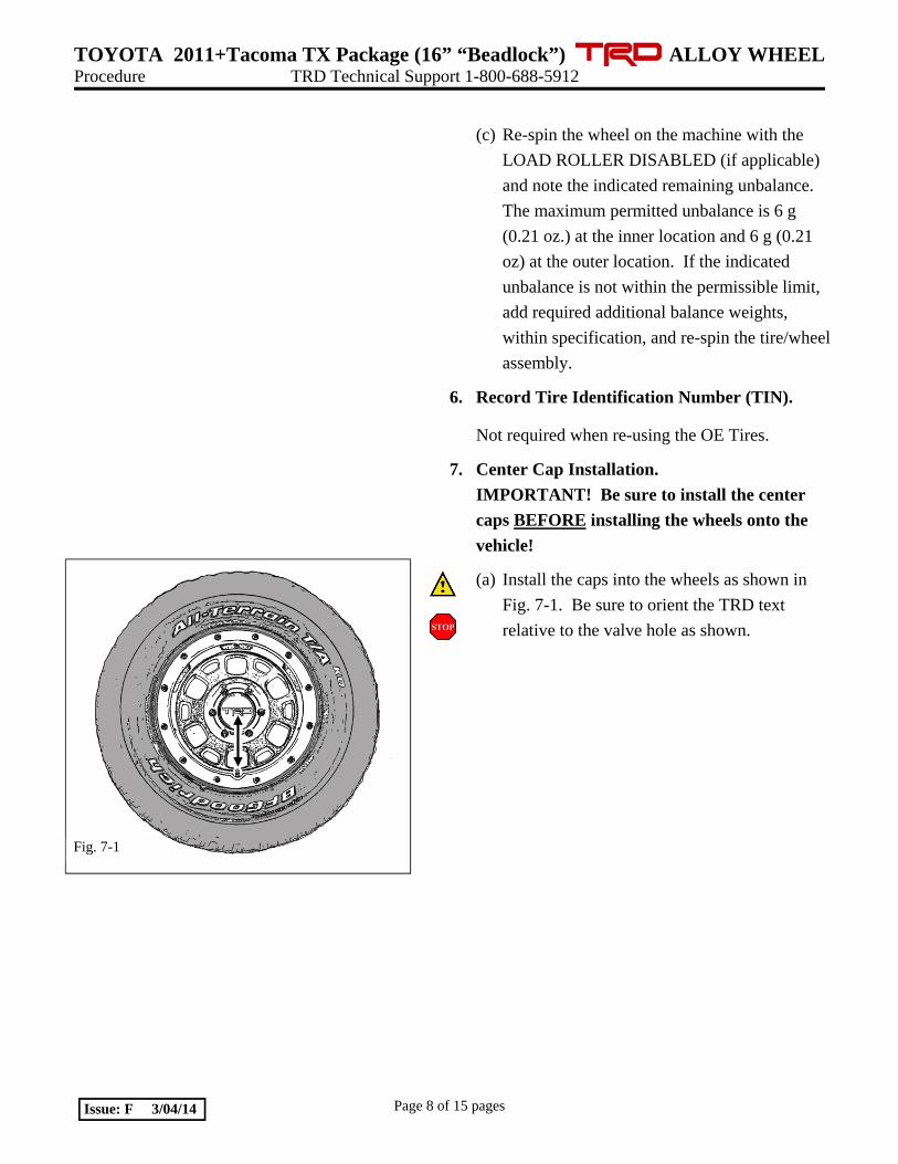
7. Center Cap Installation.
IMPORTANT! Be sure to install the center
caps BEFORE installing the wheels onto the
vehicle!
(a) Install the caps into the wheels as shown in
Fig. 7-1. Be sure to orient the TRD text
relative to the valve hole as shown.
Fig. 7-1

TOYOTA 2011+Tacoma TX Package (16” “Beadlock”) ALLOY WHEEL Procedure TRD Technical Support 1-800-688-5912
Page 9 of 15 pages Issue: F 3/04/14
Fig. 8-1
Torque 2 Cycles (All Lugs/Locks)
2x
Fig. 8-2
Measure Torque and Document (All Lugs/Locks)
8. Vehicle Wheel / Tire Installation.
(a) Install the wheel/tire assemblies onto the
vehicle. Be sure to place the wheel/tire
assemblies on the vehicle in the marked
positions from Step 1. Hand start the provided
lug nuts during installation. If wheel locks are
being added, install one wheel lock per wheel
at location 2 (or the 3 O’clock position) as in
Fig 8-1. Tighten the lug nuts in sequence 1
through 6 or equivalent star pattern (Fig. 8-1).
Ensure that the socket does not scuff the
wheels. Tighten to 83 ft-lbf (113 N-m) using
a torque wrench.
Torque: 83 ft-lbf (113 N-m)
(b) Re-torque all lug nuts in the same 1-6
sequence. (Fig. 8-1).
Torque: 83 ft-lbf (113 N-m)
CAUTION: DO NOT USE AN IMPACT
WRENCH TO INSTALL OR REMOVE
WHEEL LOCKS.
(c) With the vehicle still on the lift, use a digital
torque wrench to measure the torque of each
lug nut/lock and record it on the Torque Audit
Sheet (Fig. 8-2) (PPO installation only. Does
not apply to DIO installation).
9. Tire Pressure Labels.
Not required when re-using OE tires.

TOYOTA 2011+Tacoma TX Package (16” “Beadlock”) ALLOY WHEEL Procedure TRD Technical Support 1-800-688-5912
Page 10 of 15 pages Issue: F 3/04/14
10. TPMS Transmitter ID Registration.
Perform ONLY when replacing the sensors.
Skip to Step 12 if reusing the same 20 degree
sensors in the same vehicle.
Skip to Step 11 if using a Techstream Device.
(a) Complete this section after all four wheels
have been installed.
(b) Connect the hand-held tester to DLC3 (Fig.
10-1).
(c) Turn the ignition switch to the ON position.
(d) Turn the tester on and Select UTILITY -
REGIST TIRE following the hand-held tester
screen prompts (Fig. 10-2 & Fig. 10-3).
(e) Input the TPMS ID codes (ID1 to ID4) from
Step 3(b) using the hand-held tester to
transmit them to the tire pressure monitor
ECU.
(f) Make sure that the ID transmission condition
“SUCCEEDED” is achieved.
(g) Confirm all the tire pressures are set to values
recommended on the tire pressure label for
this vehicle.
NOTE: If this process is not completed within 5 minutes, the transmitter will return to normal operation mode and the process will need to be started over at Step(d).
Fig. 10-1
Fig. 10-2
Fig. 10-3

TOYOTA 2011+Tacoma TX Package (16” “Beadlock”) ALLOY WHEEL Procedure TRD Technical Support 1-800-688-5912
Page 11 of 15 pages Issue: F 3/04/14
11. TPMS Transmitter ID Registration Using Techstream.
(a) Connect the Techstream to DLC3, as in Fig.
10-1.
(b) Turn the ignition switch to the ON position
(do not start the vehicle) then turn the
Techstream ON.
(c) Start the Techstream application by clicking
on the shortcut located on the Desktop.
(d) Click “Connect to Vehicle” button (Fig. 11-
1).
(e) Confirm that the information displayed on the
Vehicle Connection Wizard is correct. If not,
make the appropriate selections from the Drop
Down Menus, then click “Next” (Fig. 11-2).
Fig. 11-1
Fig. 11-2

TOYOTA 2011+Tacoma TX Package (16” “Beadlock”) ALLOY WHEEL Procedure TRD Technical Support 1-800-688-5912
Page 12 of 15 pages Issue: F 3/04/14
(f) Select “Tire Pressure Monitor” then click
the green arrow located on the bottom right
(Fig. 11-3).
(g) Select “UTILITY” to begin input of new
TPMS ID codes (Fig. 11-4).
(h) Select “ID Registration” then click the green
arrow located at the bottom right corner (Fig.
11-5).
Fig. 11-5
Fig. 11-4
Fig. 11-3
TOYOTA 2011+Tacoma TX Package (16” “Beadlock”) ALLOY WHEEL Procedure TRD Technical Support 1-800-688-5912
Page 13 of 15 pages Issue: F 3/04/14
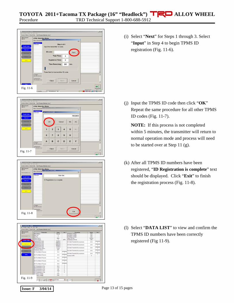
(i) Select “Next” for Steps 1 through 3. Select
“Input” in Step 4 to begin TPMS ID
registration (Fig. 11-6).
(j) Input the TPMS ID code then click “OK”
Repeat the same procedure for all other TPMS
ID codes (Fig. 11-7).
NOTE: If this process is not completed
within 5 minutes, the transmitter will return to
normal operation mode and process will need
to be started over at Step 11 (g).
(k) After all TPMS ID numbers have been
registered, “ID Registration is complete” text
should be displayed. Click “Exit” to finish
the registration process (Fig. 11-8).
(l) Select “DATA LIST” to view and confirm the
TPMS ID numbers have been correctly
registered (Fig 11-9).
Fig. 11-6
Fig. 11-7
Fig. 11-8
Fig. 11-9

TOYOTA 2011+Tacoma TX Package (16” “Beadlock”) ALLOY WHEEL Procedure TRD Technical Support 1-800-688-5912
Page 14 of 15 pages Issue: F 3/04/14
12. Tire Pressure Initialization
(a) After all tires (except the spare tire) have been
adjusted to the standard tire inflation pressure
as called out by the OE tire pressure label
found on the driver’s side door jamb, cycle the
ignition to the “IG-ON” position and check
that the Low Tire Pressure Warning Light is
OFF (Fig. 12-1).
(b) Push and Hold the Tire Pressure Warning
“SET” Switch for 3 seconds until the Low
Tire Pressure Warning Light blinks 3 times
and then turns OFF, indicating the system is
now initialized (Fig. 12-2). Refer to T-SB-
0120-10 as needed.
13. Disposition of OE Tire & Wheel Assembly
PPO: All Aluminum Take-Off Wheels & All
Steel Take-Off Wheels get salvaged according to
local regulations. OE center caps & OE lug nuts
are also salvaged.
DIO: Sort product properly according to local
regulations.
14. Lug Nut Tool Placement.
(a) Place the Spline-Drive Lug Nut Tool and
Wheel Lock Key Tool along with the lock
instruction card into vinyl pouch (PPO#
PT276-06999 / DIO# 00602-06999) and
secure it next to the OE tool bag with the OE
rubber strap & hook. Place all other
associated wheel lock paperwork into the
vehicle glove compartment.
Fig. 12-1
Fig. 12-2

TOYOTA 2011+Tacoma TX Package (16” “Beadlock”) ALLOY WHEEL Checklist - these points MUST be checked to ensure a quality installation.
Check: Look For:
Page 15 of 15 pages Issue: F 3/04/14
Inspect Lug Nuts & Torque
TPMS Torque
Record Lug & Lock Torque
Center Caps
Correct Tire Pressure
Driver Instrument Panel
Lug Nut & Lock Tools Placement
Vehicle Appearance Check
After accessory installation and removal of
protective cover(s), perform a visual
inspection.
Verify that six lug nuts/locks are installed on each wheel and wheel lock is in the correct position. Torque must be 83 ft-lbf (113 N-m). TPMS nut must be torqued to 36 in-lbf (4.0 N-m).
Measure the torque of each lug/lock on all wheels and record it on the Torque Audit Sheet (PPO installation only, does not apply to DIO installation).
Verify center caps are securely in place on all four wheels & oriented correctly.
Verify tire pressure is set to the value specified on the OE Tire Pressure Label.
Verify “TPMS warning light” is not ON
Verify the Lug Nut Tool and the Wheel Lock Key Tool are in the appropriate location in the vehicle. Ensure paperwork is placed into the vehicle glove compartment.
Ensure no damage (including scuffs and
scratches) was caused during the
installation process.
(For PPO installations, refer to TMS Accessory Quality Shipping Standard.)