Embed Size (px)
Citation preview

BODY ELECTRICAL
TOYOTATOYOTAELECTRICALELECTRICAL
WIRING DIAGRAMWIRING DIAGRAMWORKBOOKWORKBOOK
http://www.autoshop101.com
Developed by Kevin R. Sullivan Developed by Kevin R. Sullivan All Rights ReservedAll Rights Reserved
ASSIGNMENT Version 1.8WORKSHEETS
TOYOTATable of Contents
Wiring Diagrams1. Understanding Diagrams Page U-1
Lighting Systems1. Headlights Page L-12. Turnsignals & Hazard Page L-23. Stop Lights Page L-34. Automatic Light Turn-off Page L-4 5. Daytime Running Lights Page L-5
Accessories Systems1. Rear Window Defogger Page A-1 2. Power Windows Page A-23. Power Mirrors Page A-34. Door Locks Page A-4 5. Clock & Cig Lighter Page A-5 6. Front Wiper & Washer Page A-6 7. Fan & Blower Page A-7 8. Shift Lock Page A-8

TOYOTAUnderstanding
Wiring Diagrams
Worksheets
U-1 Page 1

UNDERSTANDING TOYOTA WIRING DIAGRAMS INFORMATION #1
READING TOYOTA ELECTRICAL WIRING DIAGRAMS
U-1 Page 2

UNDERSTANDING TOYOTA WIRING DIAGRAMS INFORMATION #2
TO
YO
TA
EL
EC
TR
ICA
L W
IRIN
G S
YM
BO
LS
U-1 Page 3

UNDERSTANDING TOYOTA WIRING DIAGRAMS WORKSHEET #1
1. Describe the meaning of the "C13" in the diagram component Q.2. Describe the meaning of the "G-W" in diagram component R.3. Describe the meaning of the "2" in diagram component S.4. Describe the meaning of the "S/D" in diagram component T.5. Describe and identify the diagram component U.6. Describe and identify the diagram component V.7. Describe and identify the diagram component W.8. Describe and identify the diagram component X.9. Describe and identify the diagram component Y.10. Describe and identify the diagram component Z.
X
Q
R
S
U
Z
V
W
T
Y
U-1 Page 4

UNDERSTANDING TOYOTA WIRING DIAGRAMS WORKSHEET #2
1. Draw in GREEN the HORN CONTROL circuit from the battery to ground.2. Draw in RED the HORN circuit from the battery to ground.3. Draw in BLUE the part of the circuit that is common to both the control and load (horn) circuit.
X
Z
Y
U-1 Page 5

UNDERSTANDING TOYOTA WIRING DIAGRAMS WORKSHEET #3
1. How will the circuit be affected if there were an open at point X.2. How will the circuit be affected if there were an open at point Y.3. How will the circuit be affected if there were an open at point Z.4. If the Horn Switch is OPEN, what voltage potential (Ground, Positive, or Electrically Dead) would you expect to find at point X, Y, & Z.5. If the Horn Switch is CLOSED, what voltage potential (Ground, Positive, or Electrically Dead) would you expect to find at point X, Y, & Z.
X
Z
Y
12v
U-1 Page 6
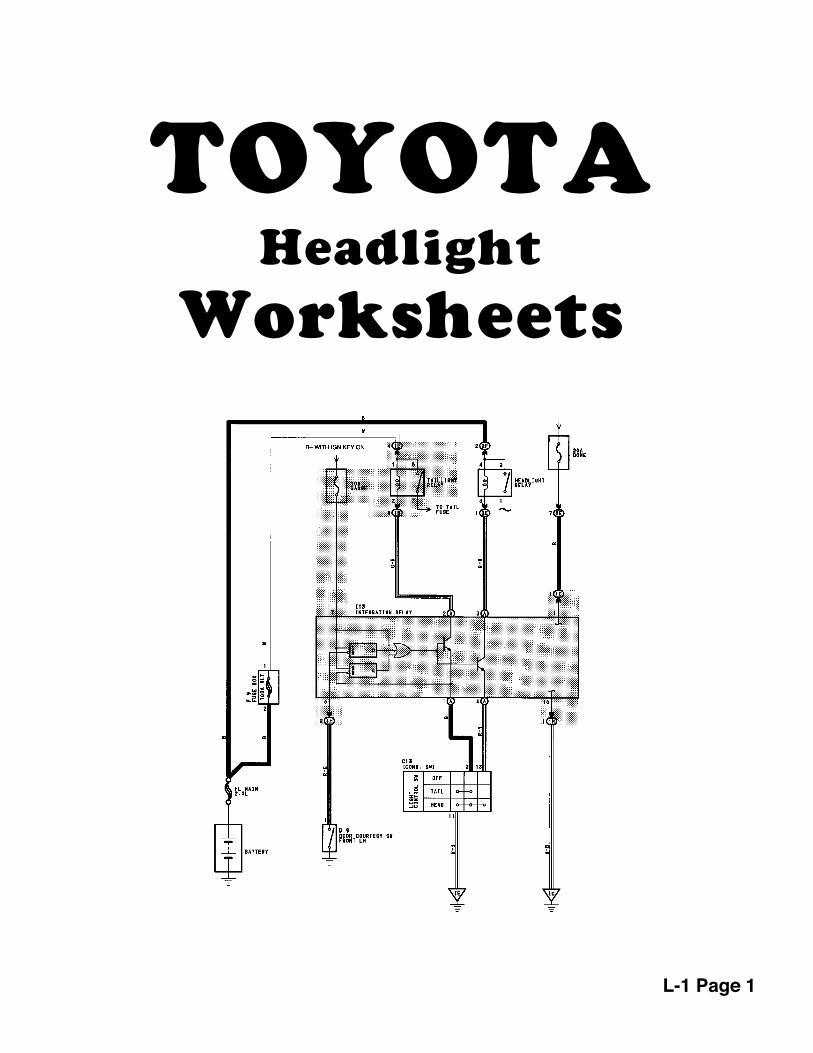
TOYOTAHeadlight
Worksheets
L-1 Page 1

TOYOTA HEADLIGHTS PRACTICE WORKSHEET
L-1 Page 2

TOYOTA HEADLIGHTS WORKSHEET #1
1. Draw in GREEN the HEAD LAMP CONTROL circuit from the battery to ground.2. Draw in RED the LOW BEAM circuit from the battery to ground.3. Draw in BLUE the HIGH BEAM circuit from the battery to ground.
L-1 Page 3

1. THE HEADLAMP SWITCH IS PLACED IN THE FLASH POSITION2. Draw in GREEN the HEAD LAMP CONTROL circuit from the battery to ground.3. Draw in BLUE the circuit through the headlamps in the FLASH position from the battery to ground.
TOYOTA HEADLIGHTS WORKSHEET #2
L-1 Page 4

1. With the Headlamp Switch in the OFF position, what voltage would you expect to find at point V, W, X, Y, & Z.2. With the Headlamp Switch in the ON position, LOW BEAM position, what voltage would you expect to find at point V, W, X, Y, & Z.3. With the Headlamp Switch in the ON position, HIGH BEAM position, what voltage would you expect to find at point V, W, X, Y, & Z.4. How will the circuit be affected if there is an open at point V.5. How will the circuit be affected if there is an open at point W.6. How will the circuit be affected if there is an open at point X.7. How will the circuit be affected if there is an open at point Y.8. How will the circuit be affected if there is an open at point Z.
X
Z
Y
W
V
TOYOTA HEADLIGHTS WORKSHEET #3
L-1 Page 5
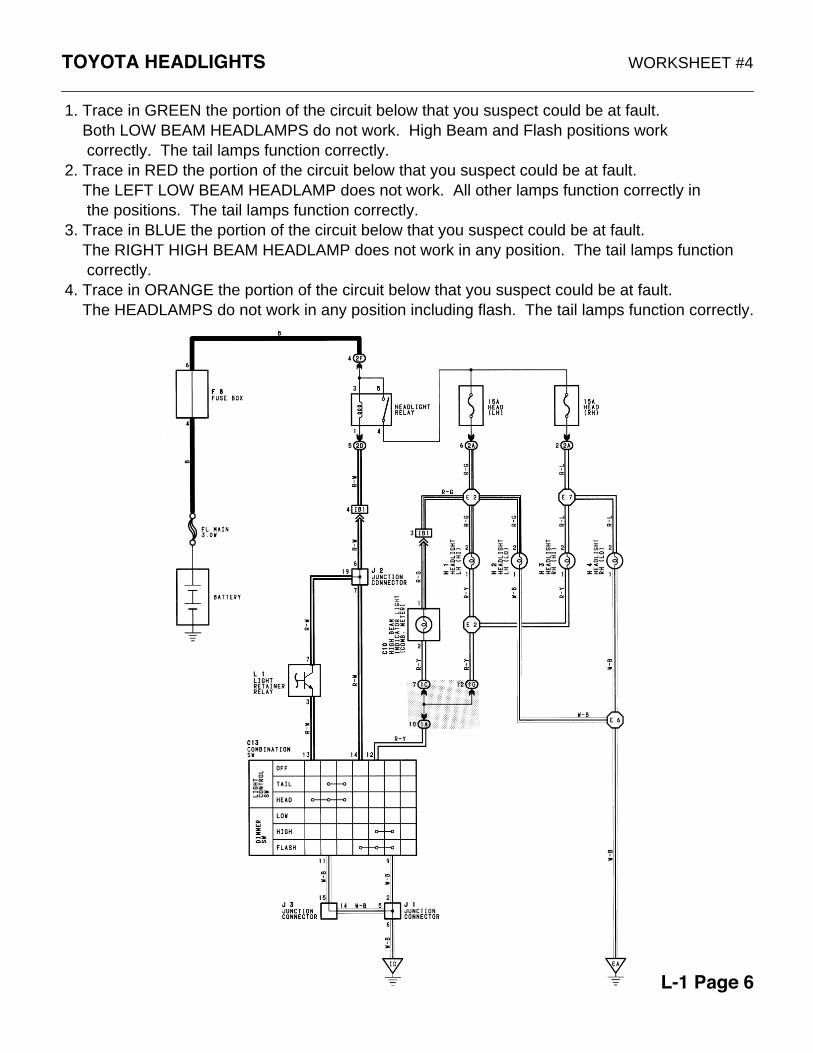
1. Trace in GREEN the portion of the circuit below that you suspect could be at fault. Both LOW BEAM HEADLAMPS do not work. High Beam and Flash positions work correctly. The tail lamps function correctly.2. Trace in RED the portion of the circuit below that you suspect could be at fault. The LEFT LOW BEAM HEADLAMP does not work. All other lamps function correctly in the positions. The tail lamps function correctly.3. Trace in BLUE the portion of the circuit below that you suspect could be at fault. The RIGHT HIGH BEAM HEADLAMP does not work in any position. The tail lamps function correctly.4. Trace in ORANGE the portion of the circuit below that you suspect could be at fault. The HEADLAMPS do not work in any position including flash. The tail lamps function correctly.
TOYOTA HEADLIGHTS WORKSHEET #4
L-1 Page 6
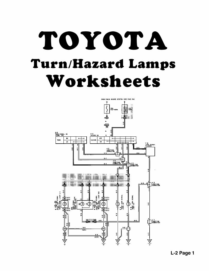
TOYOTATurn/Hazard Lamps
Worksheets
L-2 Page 1

TOYOTA TURN SIGNAL / HAZARD LAMPS REFERENCE
L-2 Page 2

TOYOTA TURN SIGNAL / HAZARD LAMPS PRACTICE WORKSHEET
L-2 Page 3

1. Draw in GREEN the RIGHT TURN LAMP circuit from the FUSE to GROUND.2. Draw in RED the LEFT TURN LAMP circuit from the FUSE to GROUND.
TOYOTA TURN SIGNAL / HAZARD LAMPS WORKSHEET #1
L-2 Page 4

1. Draw in BLUE the HAZARD circuit from the FUSE to GROUND.
TOYOTA TURN SIGNAL / HAZARD LAMPS WORKSHEET #2
L-2 Page 5

X
YW
V
Z
1. With the HAZARD SWITCH in the ON position, what voltage would you expect to find at point V, W, X, Y, & Z.2. With the RIGHT TURN SIGNAL SWITCH in the ON position, what voltage would you expect to find at point V, W, X, Y, & Z.3 How will the circuit be affected if there is an open at point V.4. How will the circuit be affected if there is an open at point W.5. How will the circuit be affected if there is an open at point X.6. How will the circuit be affected if there is an open at point Y.7. How will the circuit be affected if there is an open at point Z.
TOYOTA TURN SIGNAL / HAZARD LAMPS WORKSHEET #3
L-2 Page 6

1. Trace in GREEN the portion of the circuit below that you suspect could be at fault. TURN SIGNAL lamps do not work. The Hazard lamps function correctly.
2. Trace in RED the portion of the circuit below that you suspect could be at fault. The LEFT TURN SIGNAL does not work. The Hazard lamps function normally.
TOYOTA TURN SIGNAL / HAZARD LAMPS WORKSHEET #4
L-2 Page 7

1. Trace in BLUE the portion of the circuit below that you suspect could be at fault. The HAZARD LAMPS do not work. The Turn Signal Lamps function normally.
2. Trace in ORANGE the portion of the circuit below that you suspect could be at fault. Both the HAZARD LAMPS and the TURN SIGNAL LIGHTS do not work in any Position.
TOYOTA TURN SIGNAL / HAZARD LAMPS WORKSHEET #5
L-2 Page 8

1. Trace in BLUE the portion of the circuit below that you suspect could be at fault. The HAZARD LAMPS work the LEFT SIDE ONLY. The Turn Signal Lamps function normally.
2. Trace in GREEN the portion of the circuit below that you suspect could be at fault. The RIGHT REAR LAMP does not work with either the HAZARD LAMPS or TURN SIGNAL LIGHTS in the ON position. The other three lamps flash.
TOYOTA TURN SIGNAL / HAZARD LAMPS WORKSHEET #6
L-2 Page 9

TOYOTAStop Light
Worksheets
L-3 Page 1

TOYOTA STOP LIGHT REFERENCE
L-3 Page 2

TOYOTA STOP LIGHTS PRACTICE WORKSHEET
L-3 Page 3

TOYOTA STOP LIGHTS WORKSHEET #1
1. Identify the HIGH MOUNT STOP LAMP circuit WITHOUT a Rear Spoiler. Draw that circuit in GREEN from the battery to ground.2. Identify the HIGH MOUNT STOP LAMP circuit WITH a Rear Spoiler. Draw that circuit in Blue from the battery to ground.3. Draw in RED the B+ current path from the STOP LIGHT SWITCH to the Stop Light bulbs.
L-3 Page 4
TOYOTA STOP LIGHTS WORKSHEET #2
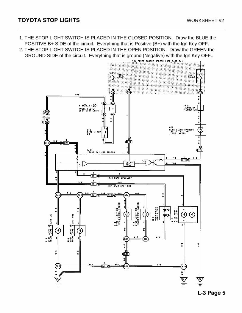
1. THE STOP LIGHT SWITCH IS PLACED IN THE CLOSED POSITION. Draw the BLUE the POSITIVE B+ SIDE of the circuit. Everything that is Positive (B+) with the Ign Key OFF.2. THE STOP LIGHT SWITCH IS PLACED IN THE OPEN POSITION. Draw the GREEN the GROUND SIDE of the circuit. Everything that is ground (Negative) with the Ign Key OFF..
L-3 Page 5
TOYOTA STOP LIGHTS WORKSHEET #3
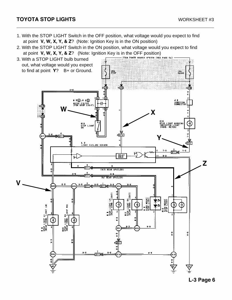
1. With the STOP LIGHT Switch in the OFF position, what voltage would you expect to find at point V, W, X, Y, & Z? (Note: Ignition Key is in the ON position)2. With the STOP LIGHT Switch in the ON position, what voltage would you expect to find at point V, W, X, Y, & Z? (Note: Ignition Key is in the OFF position)3. With a STOP LIGHT bulb burned out, what voltage would you expect to find at point Y? B+ or Ground.
Z
V
W X
Y
L-3 Page 6

TOYOTA STOP LIGHTS WORKSHEET #4
ZV
W X
Y
1. How will the circuit be affected if there is an open at point V?2. How will the circuit be affected if there is an open at point W?3. How will the circuit be affected if there is an open at point X?4. How will the circuit be affected if there is an open at point Y?5. How will the circuit be affected if there is an open at point Z?
L-3 Page 7

TOYOTA STOP LIGHTS WORKSHEET #5
1. On a vehicle without a rear spoiler. The stop lights do not work, but the high mount stop lamp works. Trace in GREEN the portion of the circuit below that could be at fault.2. On a vehicle with a rear spoiler. The high mount stop lamp does not work, but the stop lamps work fine. Trace in BLUE the portion of the circuit below that could be at fault.3. On a vehicle with a rear spoiler. A single stoplight in burned out, but the rear warning lamp indicator doesn't light. Trace in RED the portion of the circuit that could be at fault.4. On a vehicle without a rear spoiler. None of the stoplights work. Trace in ORANGE the portion of the circuit below that could be at fault.
L-3 Page 8
TOYOTAAutomatic
Light Turnoff
Worksheets
L-4 Page 1
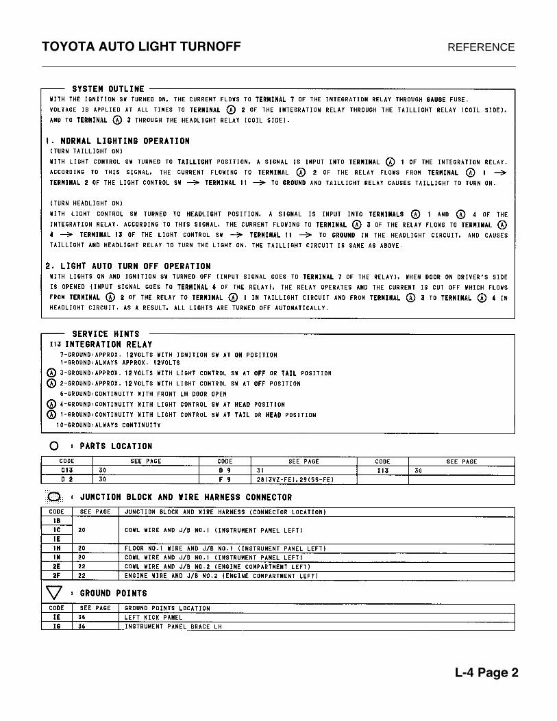
TOYOTA AUTO LIGHT TURNOFF REFERENCE
L-4 Page 2

TOYOTA AUTO LIGHT TURNOFF PRACTICE WORKSHEET
L-4 Page 3

TOYOTA AUTO LIGHT TURNOFF WORKSHEET #1
1. Draw in RED the wires that supply B+ and Ground to the Integration Relay.2. Draw in GREEN the INPUTS which are used by the Integration Relay to control the lights.3. Draw in BLUE the Control circuit from the battery to ground of the Headlamp Circuit.
L-4 Page 4

TOYOTA AUTO LIGHT TURNOFF WORKSHEET #2
1. How will the circuit be affected if there is an open at point X.
2. How will the circuit be affected if there is an open at point Y.
X
Y
L-4 Page 5

TOYOTADaytime Running Lamps
Worksheets
L-5 Page 1
Will be providedin next release.

TOYOTARear Window Defogger
Worksheets
A-1 Page 1

TOYOTA REAR WINDOW DEFOGGER REFERENCE
A-1 Page 2

TOYOTA REAR WINDOW DEFOGGER PRACTICE WORKSHEET
A-1 Page 3

TOYOTA REAR WINDOW DEFOGGER WORKSHEET #1
1. Draw in GREEN the DEFOGGER CONTROL circuit from the battery to ground.2. Draw in RED the DEFOGGER circuit from the battery to ground.3. Draw in BLUE the DEFOGGER LAMP circuit from the battery to ground.
A-1 Page 4

TOYOTA REAR WINDOW DEFOGGER WORKSHEET #2
1. With the Defogger Switch in the OFF position, what voltage would you expect to find at point V, W, X, Y, & Z ?2. With the Defogger Switch in the ON position, what voltage would you expect to find at point V, W, X, Y, & Z ?3. How will the circuit be affected if there is an open at point V ?4. How will the circuit be affected if there is an open at point W ?5. How will the circuit be affected if there is an open at point X ?6. How will the circuit be affected if there is an open at point Y ?7. How will the circuit be affected if there is an open at point Z ?
V
Y
X
Z
W
A-1 Page 5

TOYOTA REAR WINDOW DEFOGGER WORKSHEET #3
1. The rear window defroster switch lights up, but the rear window defroster does not work. Trace in BLUE the area(s) that could be at fault.
2. The rear window defroster does not work. The defroster switch light does not light either.Trace in GREEN the area(s) that could be at fault.
A-1 Page 6
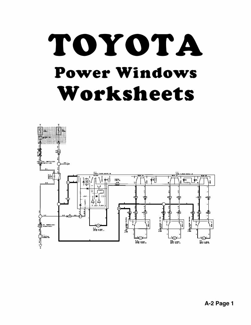
TOYOTAPower Windows
Worksheets
A-2 Page 1
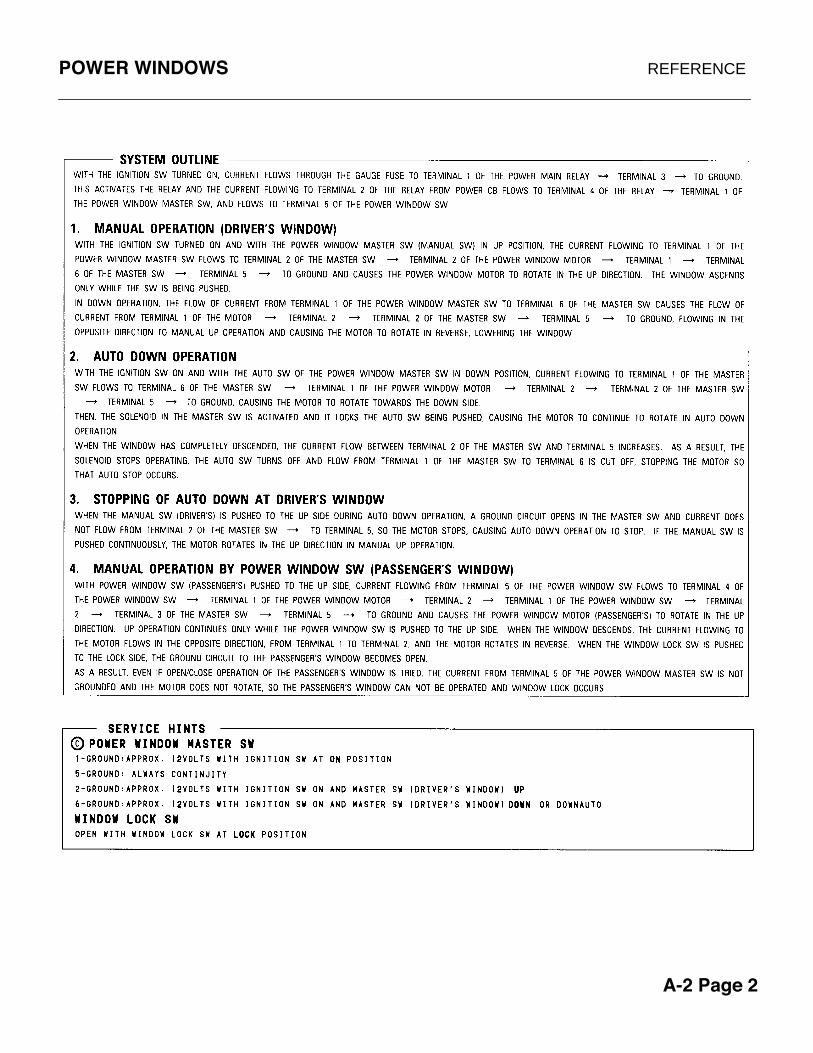
POWER WINDOWS REFERENCE
A-2 Page 2

POWER WINDOWS PRACTICE WORKSHEET
A-2 Page 3

POWER WINDOWS WORKSHEET #1
While moving the window in the DOWNposition from the PASSENGER SUBSWITCH.
1. Trace in RED the POSITIVE power flow from the fuse to the motor.
2. Trace in BLUE the NEGATIVE power flow from the motor to ground.
A-2 Page 4

POWER WINDOWS WORKSHEET #2
While moving the PASSENGER SIDE WINDOW in the UP position from the MASTER SWITCH.
1. Trace in RED the POSITIVE power flow from the fuse to the motor.
2. Trace in BLUE the NEGATIVE power flow from the motor to ground.
A-2 Page 5

POWER WINDOWS WORKSHEET #3
1. How will the circuit be affected if there is an open at point U.2. How will the circuit be affected if there is an open at point V.3. How will the circuit be affected if there is an open at point W.4. How will the circuit be affected if there is an open at point X.5. How will the circuit be affected if there is an open at point Y.6. How will the circuit be affected if there is an open at point Z.
V
Y
X
Z
U
A-2 Page 6
W

POWER WINDOWS WORKSHEET #4
The Passenger Window will not move UP or DOWN from the Master Window Switch. However, when the Sub Switch is used, the window will only move UP, and not DOWN.
1. Trace in BLUE the areas where you suspect the problem could be.
A-2 Page 7

POWER WINDOWS WORKSHEET #5
1. T
race
in R
ED
the
B+
bat
tery
vol
tage
from
the
fuse
to e
ach
of th
e w
indo
w S
UB
SW
ITC
HE
S.
2. W
hile
mov
ing
the
RIG
HT
RE
AR
win
dow
in th
e U
P p
ositi
on fr
om th
e S
UB
SW
ITC
H.
Tra
ce in
BLU
E th
e po
wer
flow
from
the
fuse
to th
e m
otor
.
T
race
in G
RE
EN
the
pow
er fl
ow fr
om th
e m
otor
to g
roun
d.
3. W
hile
mov
ing
the
RIG
HT
FR
ON
T w
indo
w in
the
DO
WN
pos
ition
from
the
SU
B S
WIT
CH
.
T
race
in O
RA
NG
E th
e po
wer
flow
from
the
fuse
all
the
way
to g
roun
d.
A-2 Page 8

POWER WINDOWS WORKSHEET #6
1. W
hile
mov
ing
the
RIG
HT
RE
AR
win
dow
in th
e U
P p
ositi
on fr
om th
e M
AS
TE
R S
WIT
CH
.
T
race
in B
LUE
the
pow
er fl
ow fr
om th
e fu
se to
the
mot
or.
Tra
ce in
GR
EE
N th
e po
wer
flow
from
the
mot
or to
gro
und.
2. W
hile
mov
ing
the
LEF
T R
EA
R w
indo
w in
the
DO
WN
pos
ition
from
the
MA
ST
ER
SW
ITC
H.
Tra
ce in
OR
AN
GE
the
pow
er fl
ow fr
om th
e fu
se a
ll th
e w
ay to
gro
und.
A-2 Page 9

POWER WINDOWS WORKSHEET #7
A-2 Page 10
1. T
he R
ight
Rea
r W
indo
w w
ill n
ot r
oll u
p or
dow
n fr
om th
e S
ub S
witc
h, h
owev
er th
e w
indo
w w
orks
cor
rect
ly fr
om th
e M
aste
r S
witc
h. T
race
in B
LUE
the
area
s w
here
the
prob
lem
cou
ld b
e.
2. T
he L
eft R
ear
Win
dow
will
not
rol
l up
or d
own
from
eith
er th
e S
ub a
nd M
aste
r S
witc
hes.
Tra
ce in
RE
D th
e ar
eas
whe
re th
e pr
oble
m c
ould
be.
3. A
ll of
the
Win
dow
s w
ill n
ot r
oll u
p or
dow
n fr
om e
ither
the
Sub
and
Mas
ter
Sw
itche
s.
T
race
in G
RE
EN
the
area
s w
here
the
prob
lem
cou
ld b
e.
4. B
oth
Rea
r W
indo
ws
will
not
rol
l up
or d
own
from
eith
er th
e S
ub a
nd M
aste
r S
witc
hes.
Tra
ce in
OR
AN
GE
the
area
s w
here
the
prob
lem
cou
ld b
e.

TOYOTAPower Mirrors
Worksheets
A-3 Page 1

POWER MIRRORS REFERENCE
A-3 Page 2

POWER MIRRORS PRACTICE WORKSHEET
A-3 Page 3
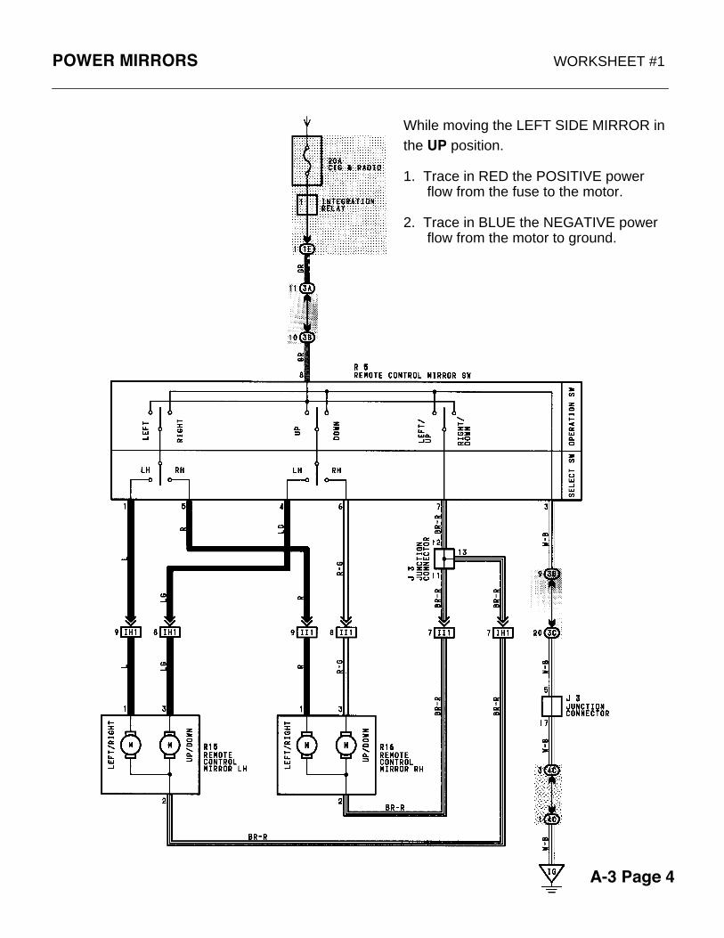
POWER MIRRORS WORKSHEET #1
While moving the LEFT SIDE MIRROR in the UP position.
1. Trace in RED the POSITIVE power flow from the fuse to the motor.
2. Trace in BLUE the NEGATIVE power flow from the motor to ground.
A-3 Page 4

POWER MIRRORS WORKSHEET #2
While moving the LEFT SIDE MIRROR in the DOWN position.
1. Trace in RED the POSITIVE power flow from the fuse to the motor.
2. Trace in BLUE the NEGATIVE power flow from the motor to ground.
A-3 Page 5

POWER MIRRORS WORKSHEET #3
While moving the RIGHT SIDE MIRROR to the RIGHT.
1. Trace in RED the POSITIVE power flow from the fuse to the motor.
2. Trace in BLUE the NEGATIVE power flow from the motor to ground.
A-3 Page 6

POWER MIRRORS WORKSHEET #4
While moving the LEFT SIDE MIRROR to the LEFT.
1. Trace in RED the POSITIVE power flow from the fuse to the motor.
2. Trace in BLUE the NEGATIVE power flow from the motor to ground.
A-3 Page 7

POWER MIRRORS WORKSHEET #5
Determine what the affect will be on thefollowing circuit.
1. How will the circuit be affected if there is an open at point V.2. How will the circuit be affected if there is an open at point W.3. How will the circuit be affected if there is an open at point X.4. How will the circuit be affected if there is an open at point Y.5. How will the circuit be affected if there is an open at point Z.
W
Z
YV
X
A-3 Page 8

POWER MIRRORS WORKSHEET #6
PROBLEM #1
The LEFT MIRROR will NOT adjust UP or DOWN. However, the LEFT MIRROR will adjust LEFT and RIGHT. The RIGHT MIRROR functions correctly.
Trace in BLUE the areas where the problem could be.
PROBLEM #2
The RIGHT MIRROR will NOT adjust UP,DOWN, LEFT,or RIGHT. The LEFT MIRROR functions correctly.
Trace in RED the areas where the problem could be.
A-3 Page 9

POWER MIRRORS WORKSHEET #7
PROBLEM #3
The LEFT MIRROR will NOT adjust LEFT or RIGHT. However, the LEFT MIRROR will adjust UP and DOWN. The RIGHT MIRROR functions correctly.
Trace in BLUE the areas where the problem could be.
PROBLEM #4
The LEFT MIRROR will NOT adjust UP,DOWN, LEFT,or RIGHT. The RIGHT MIRROR functions correctly.
Trace in RED the areas where the problem could be.
A-3 Page 10

POWER MIRRORS WORKSHEET #8
PROBLEM #6
Both the LEFT & RIGHT MIRRORS will NOT adjust UP or DOWN However, both the LEFT & RIGHT MIRRORS will adjust LEFT and RIGHT.
Trace in RED the areas where the problem could be.
A-3 Page 11
PROBLEM #5
Both the LEFT & RIGHT MIRRORS will not function.
Trace in BLUE the areas where the problem could be.

TOYOTADoor Looks
Worksheets
A-4 Page 1
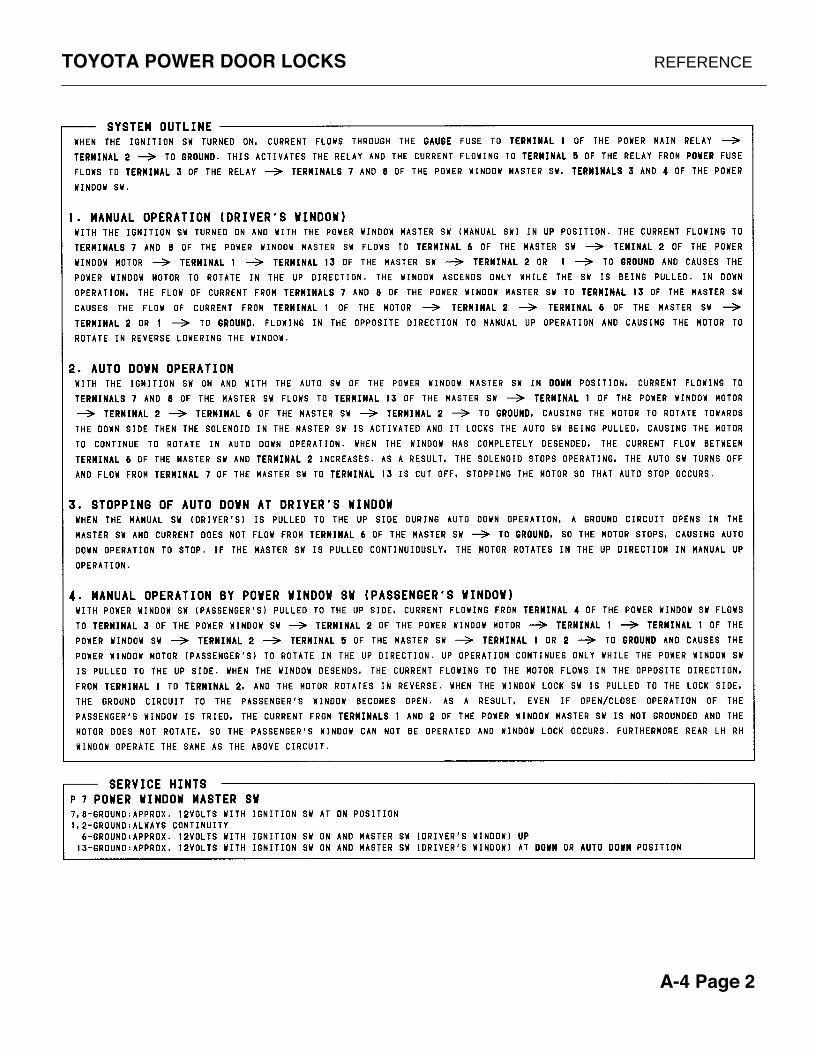
TOYOTA POWER DOOR LOCKS REFERENCE
A-4 Page 2

TOYOTA POWER DOOR LOCKS PRACTICE WORKSHEET
A-4 Page 3

A-4 Page 4
TOYOTA POWER DOOR LOCKS WORKSHEET #1

TOYOTA POWER DOOR LOCKS WORKSHEET #2
A-4 Page 5
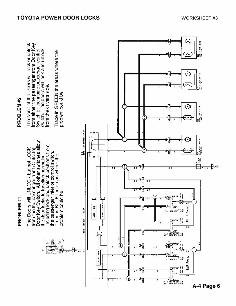
TOYOTA POWER DOOR LOCKS WORKSHEET #3
A-4 Page 6

TOYOTA POWER DOOR LOCKS WORKSHEET #4
A-4 Page 7

TOYOTA POWER DOOR LOCKS WORKSHEET #5
A-4 Page 8

TOYOTAClock/Cig Circuit
Worksheets
A-5 Page 1

TOYOTA CLOCK/CIG REFERENCE
A-5 Page 2

TOYOTA CLOCK/CIG PRACTICE WORKSHEET
A-5 Page 3

TOYOTA CLOCK/CIG WORKSHEET #1
1. Trace in RED the part of the clock's circuit that allows the clock's display to light.
2. Trace in BLUE the part of the clock's circuit that allows the Clock to keep the correct time when the engine is not running (Memory).
3. Trace in GREEN the part of the clock's circuit that allows the Clock's display to dim when the headlights are turned on.
A-5 Page 4

TOYOTA CLOCK/CIG WORKSHEET #2
1. How will the circuit be affected if there is an open at point X.
2. How will the circuit be affected if there is an open at point Y.
3. How will the circuit be affected if there is an open at point Z.
Y
X
Z
A-5 Page 5

TOYOTA CLOCK/CIG WORKSHEET #3
A-5 Page 6
1. The clock display will not dim when the headlamps are turned on.Trace in RED the area(s) that could be at fault.
2. The clock loses its time (memory) each time the ignition switch is turned off and has to be reset with the correct time.Trace in BLUE the area(s) that could be at fault.
3. The clock display never light up. The cigarette lighter works.Trace in GREEN the area(s) that could be at fault.

TOYOTAWiper/Washer Circuit
Worksheets
A-6 Page 1

FRONT WIPERS REFERENCE
A-6 Page 2

FRONT WIPERS PRACTICE WORKSHEET
A-6 Page 3

FRONT WIPERS WORKSHEET #1
The WIPER SWITCH is in the LOW SPEED position.
1. Trace in RED the POSITIVE power flow from the fuse to the motor.
2. Trace in BLUE the NEGATIVE power flow from the motor to ground.
A-6 Page 4

FRONT WIPERS WORKSHEET #2
With the WIPER SWITCH is in the HIGH SPEED position.
1. Trace in RED the POSITIVE power flow from the fuse to the motor.
2. Trace in BLUE the NEGATIVE power flow from the motor to ground.
A-6 Page 5

FRONT WIPERS WORKSHEET #3
The WIPER SWITCH is turned to the OFF postion while the wipers are in the up position on the windshield. The wipers continue to move until they reach the park position at the bottom of the windshield. Identify and draw this circuit .
1. Trace in RED the POSITIVE power flow from the fuse to the motor.
2. Trace in BLUE the NEGATIVE power flow from the motor to ground.
A-6 Page 6
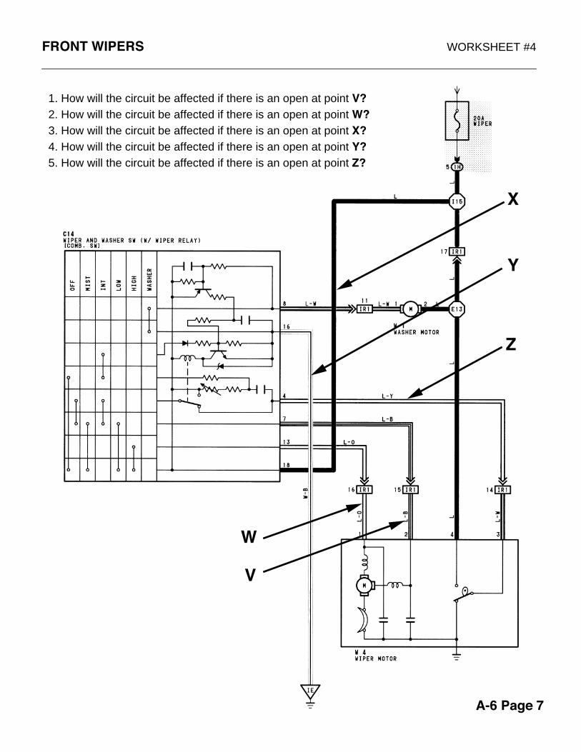
FRONT WIPERS WORKSHEET #4
1. How will the circuit be affected if there is an open at point V?2. How will the circuit be affected if there is an open at point W?3. How will the circuit be affected if there is an open at point X?4. How will the circuit be affected if there is an open at point Y?5. How will the circuit be affected if there is an open at point Z?
X
Y
W
V
Z
A-6 Page 7

FRONT WIPERS WORKSHEET #5
1. The Wipers will not work in the low speed position. All other positions function correctly (high speed, intermittent, park, and mist). Trace in RED the area(s) that could be at fault.
2. The Wipers will not work in any position, however the washer motor works but with no wipers . Trace in BLUE the area(s) that could be at fault.
A-6 Page 8

FRONT WIPERS WORKSHEET #6
1. The Wipers will not work in the High Speed position. All other positions function correctly. Trace in RED the area(s) that could be at fault.
2. The Wipers stay up on the windshield when the wiper switch is turned off. All other wiper functions work correctly (high, low, mist, etc.) Trace in BLUE the area(s) that could be at fault.
A-6 Page 9

FRONT WIPERS WORKSHEET #7
1. Only the High Speed position works. All other positions (Low, Intermittent, Mist, Park, etc. will not function. Trace in RED the area(s) that could be at fault.
2. The Intermittent Wipers do not work. All other wiper functions work correctly (high, low, mist, etc.) Trace in BLUE the area(s) that could be at fault.
A-6 Page 10

TOYOTAFan & Blower Circuits
Worksheets
A-7 Page 1

COOLING FANS / BLOWER REFERENCE #A
A-7 Page 2
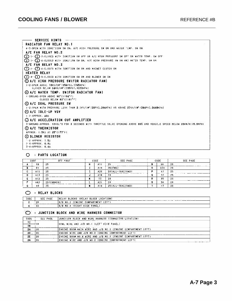
COOLING FANS / BLOWER REFERENCE #B
A-7 Page 3

COOLING FANS / BLOWER PRACTICE WORKSHEET
A-7 Page 4

COOLING FANS / BLOWER WORKSHEET #1
1. Draw in RED the fan circuit with the FANS in HIGH SPEED operation.
2. Draw in Blue the fan circuit with theFANS in LOW SPEED operation.
3. In HIGH SPEED FAN MODE what is the state of each of the three relays.The air conditioning is off.Relay #1: ON / OFFRelay #2: ON / OFFRelay #3: ON / OFF
4. In LOW SPEED FAN MODE what is the state of each of the three relays.Relay #1: ON / OFFRelay #2: ON / OFFRelay #3: ON / OFF
5. How or when is relay #3 energized?
_________________________________
_________________________________
6. How or when is relay #2 energized?
_________________________________
_________________________________
_________________________________
7. What will happen to the Radiator Fan and the Radiator Fan Relay #1 when the Water Temp Sensor senses 199ºf.
_________________________________
_________________________________
_________________________________ A-7 Page 5
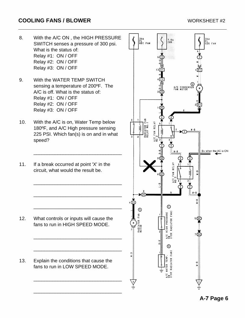
COOLING FANS / BLOWER WORKSHEET #2
8. With the A/C ON , the HIGH PRESSURE SWITCH senses a pressure of 300 psi. What is the status of:Relay #1: ON / OFFRelay #2: ON / OFFRelay #3: ON / OFF
9. With the WATER TEMP SWITCH sensing a temperature of 200ºF. TheA/C is off. What is the status of:Relay #1: ON / OFFRelay #2: ON / OFFRelay #3: ON / OFF
10. With the A/C is on, Water Temp below 180ºF, and A/C High pressure sensing 225 PSI. Which fan(s) is on and in what speed?
_________________________________
11. If a break occurred at point 'X' in the circuit, what would the result be.
_________________________________
_________________________________
_________________________________
12. What controls or inputs will cause the fans to run in HIGH SPEED MODE.
_________________________________
_________________________________
13. Explain the conditions that cause the fans to run in LOW SPEED MODE.
_________________________________
_________________________________
A-7 Page 6

COOLING FANS / BLOWER WORKSHEET #3
14. If a break occurred at point 'V' in the circuit , what would the result be.
______________________________
______________________________
______________________________
15. If a break occurred at point 'X' in the circuit , what would the result be.
______________________________
______________________________
______________________________
16. If a break occurred at point 'Y' in the circuit , what would the result be.
______________________________
______________________________
______________________________
17. If a break occurred at point 'Z' in the circuit , what would the result be.
______________________________
______________________________
______________________________
A-7 Page 7
Z
X
Y
V

COOLING FANS / BLOWER WORKSHEET #4
1. Both FANS will not work in LOW SPEED. The Fans only work in HIGH SPEED.Trace in RED the area(s) that could be at fault.
2. The RADIATOR FAN will not work in HIGH SPEED, however it will work in LOW SPEED when the AC switch is turned on.Trace in BLUE the area(s) that could be at fault.
3. The CONDENSER FAN works all the time and will not shut off. The RADIATOR FAN works only in HIGH SPEED but not in low speed.Trace in GREEN the area(s) that could be at fault.
4. The FANS will not turn on when the engine overheats. The fans work correctly in the other positions.Trace in Orange the area(s) that could be at fault.
A-7 Page 8

COOLING FANS / BLOWER WORKSHEET #5
1. Draw in RED the Blower CONTROL CIRCUIT with the blower motor in operation.
2. Draw in BLUE the BLOWER CIRCUIT with the BLOWER in the LOW SPEED position.
3. Draw in GREEN the BLOWER CIRCUIT with the BLOWER in M1 SPEED position.
4. Draw in ORANGE the BLOWER CIRCUIT with the BLOWER in HIGH SPEED position.
5. Explain the difference between the HI SPEED circuit and ALL OTHER SPEEDS.
______________________________
______________________________
______________________________
______________________________
______________________________
7. How does the Heater Relay remain energized while different blower positions are selected.
______________________________
______________________________
______________________________
______________________________
______________________________A-7 Page 9

Y
X
Z
V
U
COOLING FANS / BLOWER WORKSHEET #6
8. If a break occurred at point 'V' in the circuit , what would the result be.
_________________________________
_________________________________
_________________________________
9. If a break occurred at point 'X' in the circuit , what would the result be.
_________________________________
_________________________________
_________________________________
10. If a break occurred at point 'Y' in the circuit , what would the result be.
_________________________________
_________________________________
_________________________________
11. If a break occurred at point 'Z' in the circuit , what would the result be.
_________________________________
_________________________________
_________________________________
A-7 Page 10

COOLING FANS / BLOWER WORKSHEET #7
1. Only the HIGH SPEED blower works.None of the other blower speeds work.Trace in RED the area(s) that could be at fault.
2. The LOW SPEED blower does not work. All other speeds work correctly.Trace in BLUE the area(s) that could be at fault.
3. The blower does not work. A "click" from the relay is heard when the blower switch is placed any one of the blower speed positionsTrace in GREEN the area(s) that could be at fault.
4. When the blower switch is placed into the M2 (medium 2). The fan operates in low speed rather than M2. All other blower speed positions operate correctlyTrace in ORANGE the area(s) that could be at fault.
A-7 Page 11

TOYOTAShift Lock Circuit
Worksheets
A-8 Page 1

SHIFT LOCK REFERENCE
A-8 Page 2

SHIFT LOCK PRACTICE WORKSHEET
A-8 Page 3

SHIFT LOCK WORKSHEET #1
A-8 Page 4
1. When is Switch SW1 closed and when is it open?2. When is Switch SW2 closed and when is it open?
3. What is the function of the Key Interlock Solinoid?4. What is the function of the Shift Lock Solinoid?5. What is the function of Logic Gate L1?
6. What circuit or component does Transistor TR1 control?7. What circuit or component does Transistor TR2 control?8. What circuit or component does Logic Gate L1 control?
Hint: Use the Reference PageA-9 Page 2

SHIFT LOCK WORKSHEET #2
A-8 Page 5
1. Trace in RED the B+ input to Logic Gate L1 inside the Shift Lock ECU, when the Stop Light is closed.
2. Trace in BLUE the Ground input to Logic Gate L2 (NOT Gate) inside the Shift Lock ECU.
3. Trace in GREEN the positive output from Logic Gate L2 to base of Transistor TR2.
4. Trace in ORANGE the Shift Lock Solenoid Circuit (from the fuse to ground) that is controlled by Transistor TR2 (emitter-collector circuit of TR2).
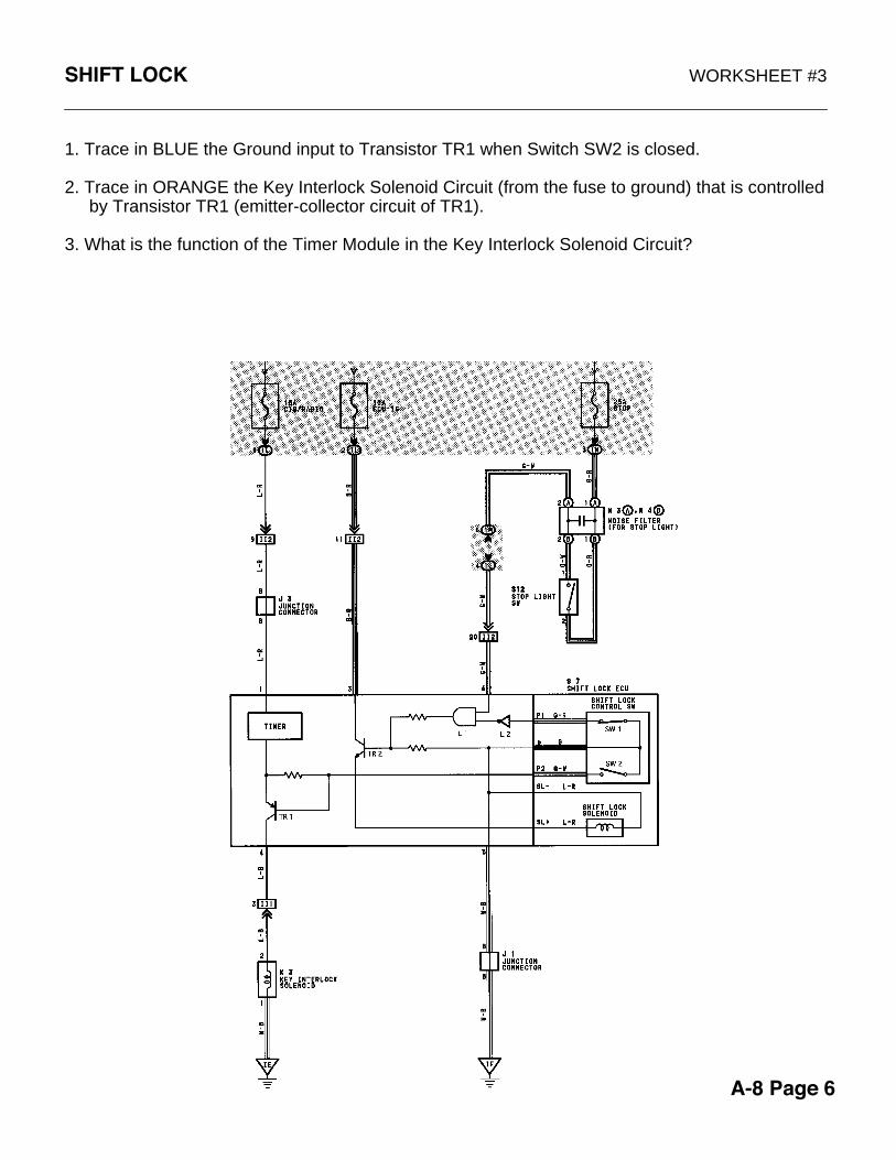
SHIFT LOCK WORKSHEET #3
A-8 Page 6
1. Trace in BLUE the Ground input to Transistor TR1 when Switch SW2 is closed.
2. Trace in ORANGE the Key Interlock Solenoid Circuit (from the fuse to ground) that is controlled by Transistor TR1 (emitter-collector circuit of TR1).
3. What is the function of the Timer Module in the Key Interlock Solenoid Circuit?

SHIFT LOCK WORKSHEET #4
A-8 Page 7
T
Z
YX
V
R
S
W
U
Determine what the affect will be on the following circuit.1. How will the circuit be affected if there is an open at point S.2. How will the circuit be affected if there is an open at point T.3. How will the circuit be affected if there is an open at point U.4. How will the circuit be affected if there is an open at point V.5. How will the circuit be affected if there is an open at point W.6. How will the circuit be affected if there is an open at point X.7. How will the circuit be affected if there is an open at point Y.8. How will the circuit be affected if there is an open at point Z.

SHIFT LOCK WORKSHEET #5
A-8 Page 8
1. The SHIFT LEVER will not move out of Park. Trace in RED the area(s) that could be at fault.
2. The IGNITION KEY will not turn to the LOCK position. Trace in BLUE the area(s) that could be at fault.


