Embed Size (px)
Citation preview

C
T
Pa
b
a
ARRAA
KErMRRSTT
1
f1ecitip
tatfittoeeb
0d
The Journal of Systems and Software 85 (2012) 2205– 2227
Contents lists available at SciVerse ScienceDirect
The Journal of Systems and Software
jo u rn al hom epage: www.elsev ier .com/ locate / j ss
ontroversy Corner
owards automated traceability maintenance
atrick Mädera,∗, Orlena Gotelb
Institute for Systems Engineering and Automation (SEA), Johannes Kepler University, Linz, AustriaIndependent Researcher, New York, USA
r t i c l e i n f o
rticle history:eceived 18 November 2010eceived in revised form 27 July 2011ccepted 19 October 2011vailable online 25 October 2011
eywords:vent-based development activity
a b s t r a c t
Traceability relations support stakeholders in understanding the dependencies between artifacts cre-ated during the development of a software system and thus enable many development-related tasks. Toensure that the anticipated benefits of these tasks can be realized, it is necessary to have an up-to-date setof traceability relations between the established artifacts. This goal requires the creation of traceabilityrelations during the initial development process. Furthermore, the goal also requires the maintenanceof traceability relations over time as the software system evolves in order to prevent their decay. Inthis paper, an approach is discussed that supports the (semi-) automated update of traceability relations
ecognitionodel changes
equirements traceabilityule-based traceability maintenanceoftware system evolutionraceability decayraceability maintenance
between requirements, analysis and design models of software systems expressed in the UML. This ismade possible by analyzing change events that have been captured while working within a third-partyUML modeling tool. Within the captured flow of events, development activities comprised of severalevents are recognized. These are matched with predefined rules that direct the update of impacted trace-ability relations. The overall approach is supported by a prototype tool and empirical results on theeffectiveness of tool-supported traceability maintenance are provided.
. Introduction
Traceability provides for a logical connection between arti-acts of the software development process (Gotel and Finkelstein,994). In support of change management tasks, traceability deliv-rs important information about the possible consequences of ahanging requirement. For project management tasks, traceabil-ty supports the control of a project’s progress and provides a wayo demonstrate the realization of user requirements. Traceabilitys essential for numerous quality-oriented software developmentractices such as these.
Though widely accepted as beneficial, the costs associated withraceability can be high, so the return on investment remains debat-ble (Arkley and Riddle, 2005; Egyed et al., 2007). Unless mandated,raceability is rarely used throughout all development stages, duerstly to the number of artifacts or elements therein that often needo be related to yield value, and due secondly to the need to main-ain these relations each time a change occurs. Even where the setf relations is minimal, the maintenance of traceability demandsffort. While attention has been directed toward approaches for
stablishing traceability initially among artifacts, less attention haseen paid to ensuring this traceability remains correct over time.∗ Corresponding author.E-mail addresses: [email protected] (P. Mäder), [email protected] (O. Gotel).
164-1212/$ – see front matter © 2011 Elsevier Inc. All rights reserved.oi:10.1016/j.jss.2011.10.023
© 2011 Elsevier Inc. All rights reserved.
This is the problem of traceability decay and is the focus of thispaper.
The maintenance of traceability relations is a multi-step activ-ity. As changes occur to the artifacts of software development,it is essential to appreciate both where and how these artifactsplay a role with respect to the current traceability, along with anunderstanding of the encompassing development activity that cancharacterize the nature of the change. It is then necessary to under-stand the impact of the development activity on the traceability andto carry out those activities that can re-establish the traceability, atleast to the prior levels. These core tasks demand effective methodand tool support. This paper describes a novel approach for themaintenance of requirements traceability relations. The approachcurrently supports development models expressed in structuralUnited Modeling Language (UML) diagrams and converts part ofthe manual effort necessary for traceability maintenance into com-putational effort. There are two important innovations with theapproach: first is the automatic identification of development activ-ities with impact on existing traceability relations (event-baseddevelopment activity recognition); and second is the use of rulesto describe development activities and the necessary updates in anabstract way (rule-based traceability maintenance). The approachis (semi-) automated as, depending on the nature of the change and
the status of the existing traceability, the user may have to provideinput to the process.In this paper, we provide an exhaustive and mature descriptionof an approach that we have developed over the past several years.

2206 P. Mäder, O. Gotel / The Journal of Systems
ability needs for a new proje ct and later usage
Creating and maintaining traceabili ty
Using t raceability
Project with up-to-date
Information need th at requi res t raceabili ty usage
Changing a model with traceabili ty impa ct
Information need that cannot be
traceabili ty
CtMenadrauoptm(t
tpioac
2
ftfaAdarsP
itrLr
fti(Htno
Fig. 1. Traceability life cycle for a project
ertain parts of the approach have been published previously. Inhree prior publications we discussed aspects of the approach,
äder et al. (2008a) gave an initial overview of the approach, Mädert al. (2008b) discussed technical details of one particular compo-ent of the approach, namely the development activity recognition,nd Mäder et al. (2009a) referred to link update concepts and intro-uced different types of development activities according to theequired update. In addition, tool demonstration papers provide forn overview of the development prototype. The most complete andp-to-date tool information is provided in Mäder et al. (2009b). Thebjective of this current paper is to consolidate the work into onerimary publication at the requisite level of detail. Building upon ahorough analysis of the state of the art in the field of traceability
aintenance, the current paper demonstrates and discusses how asemi-) automated approach in this topic can convert large parts ofedious and error-prone manual effort into computational effort.
The paper is organized as follows. The topic of traceability main-enance and related research is discussed in Section 2. Section 3rovides a conceptual overview of the entire approach, outlining
ts scope, assumptions and phases. Sections 4 and 5 provide depthn the two main phases of the approach, and an evaluation of thepproach is described in Section 6. The paper concludes with aritical review and suggestions for future research in the area.
. Traceability maintenance
Providing traceability for a project is not a trivial matter; dif-erent activities are necessary to both create and then maintainraceability relations, as suggested in Fig. 1. An agreed methodologyor traceability, specifying how to create, maintain and use trace-bility, is not generally available (Aizenbud-Reshef et al., 2006).n important reason for this absence is the high variability inevelopment processes used in practice. Nevertheless, common toll processes is the necessity to specify which artifacts should beelated and how this information should be used to obtain a con-istent set of traceability relations across developers (Dömges andohl, 1998).
Pinheiro (2004) divides the ‘production’ of traceability relationsnto perception, registration and maintenance. Other authors refero the registration as creating, establishing or installing traceabilityelations. These terms will be used interchangeably in this paper.ikewise, traceability maintenance and update, and traceabilityelation and link, will be used synonymously.
In recent years, much research has been dedicated to techniquesor the automated identification and creation of traceability rela-ions. The majority of these approaches apply text mining andnformation retrieval techniques to identify candidate relationsAlexander, 2002; Antoniol et al., 2002; Marcus and Maletic, 2003;
ayes et al., 2003; Lucia et al., 2008). Even with these emergingechniques, manual intervention to prune candidate relations can-ot be completely avoided. One day it may be viable to simply relyn automated trace generation on demand and as needed, but that
and Software 85 (2012) 2205– 2227
requires substantive advances in the precision of these techniquesto remove the need for continual re-confirmation of the candidaterelations. An alternative is to generate a quality set, through thesetechniques and manual pruning, and then to focus on maintain-ing them. This paper focuses on the latter strategy. There has beenless research work on the automated maintenance of traceabil-ity relations. Maintaining traceability means to prevent its decaywhile related artifacts evolve. Aizenbud-Reshef et al. (2006) referto maintenance as the most challenging aspect of traceability.
Murta et al. (2006) characterize the problem of traceabilitymaintenance between architectural elements and source code asfollows: “. . .given an initial set of established traceability links,and given that both an architecture and its implementation canevolve independently, how can traceability links be updated withthe addition of new links, removal of existing links, and changesin existing links to ensure that each architectural element is at alltimes accurately linked to its corresponding source code configu-ration items, and vice versa?” Without maintenance, traceabilityrelations between elements get lost or represent false dependen-cies. Such a step by step degradation of traceability relations leadsto traceability decay. This can be prevented by continuous or on-demand traceability maintenance. On-demand maintenance offersthe theoretical benefit that relations are only updated according tothe current state of the model, with potentially fewer incremen-tal update steps as compared to continuous maintenance. On theother hand, the demand for updated traceability might arise a longtime after the change to the model that has caused the need formaintenance and it might be harder to perform than instantaneouscontinuous maintenance. From a theoretical point of view, bothoptions have advantages and disadvantages, highlighting the needfor further empirical studies in this area. It would be important toindependently assess the quality of the traceability relations estab-lished, as a result of following the two strategies, with respect to ashared set of traceability-enabled tasks demanding impact analysisand change management. Moreover, the value of blending contin-uous and on-demand approaches to maintenance suggests an areaof open research.
This section explains why traceability maintenance becomesnecessary during the development and evolution of a software sys-tem. It also discusses the strengths and weaknesses of existingapproaches to the problem in order to put the approach proposedin this paper into context.
2.1. Why traceability maintenance is necessary
A common way to cope with the complexity of software systemsengineering is modeling the product to be developed at differentlevels of abstraction and from different perspectives. This processis called model-based development. A model can be defined as anabstraction of some real world object and, in the context of a devel-opment process, it refers to the product which is the subject ofengineering (OMG, 2003, 2010). In software engineering activities,models can be used to represent the requirements, the design andthe implementation of a software system. As all the models of onedevelopment project describe different aspects of the same prod-uct, they are interrelated. For example, the design of a softwaresystem depends on its requirements, while the implementationdepends on its design. The (OMG, 2010) provides a set of structuraland behavioral diagrams that allow many facets of a developmentprocess to be modeled. The UML is further supported by manymodeling tools and is the quasi-standard in object-oriented devel-opment. An extension, the Systems Modeling Language (SysML)
(OMG, 2008), provides additional diagrams and options for systemsdevelopment.Model-based development processes may be viewed as multi-phase transformation processes from the initial problem statement

P. Mäder, O. Gotel / The Journal of Systems and Software 85 (2012) 2205– 2227 2207
«trace»
«trace»
«trace»
Outgoing traceability relations
Incoming traceability relation
Independent model element
Dependent model element
Ft
tainttcsaefwfwmc
c2aatdvAdbwda2
ot(tfipa2
mbo
method
Changing an eleme nt in one model ( e. g., chan ging a use case)
«trace» «t race» «t race» «trace»
class
I. No impact on rel ated element
II. Changes to the rel ated element a re ne cessary, but
no impact on t raceabili ty
III. Changes to the rel ated element and to t raceabili ty
rel ations a re ne cessa ry
att ribu te
+
+
+ –att ribu te
+
Fig. 3. Changing an element in one model can have different impact on related
2.2.2. Rule-based approaches
ig. 2. Distinction of traceability relations into incoming and outgoing relative tohe selected element within a model
o the final solution (Jacobson et al., 1999). These transformationsre carried out as development activities. Each of these activitiess applied to or influenced by various input artifacts and createsew or improved output artifacts. If this multiphase transforma-ion process is carried out only once, entering each phase only whenhe preceding phase has been completed, it is a waterfall-like pro-ess (Royce, 1987). Most problems nowadays are too complex to beolved in this manner and state of the art development processesre iterative and incremental (e.g., the Unified Process; Jacobsont al., 1999). Moreover, development does not always proceed in aorward direction (forward engineering). Rather, it may also involveorking in a backward direction (reverse engineering). Combining
orward and reverse engineering results in round-trip engineering,here developers opportunistically mix both modes of develop-ent. This mode of development necessitates interrelated model
hanges.Creating an explicit traceability relation between two artifacts
an capture their dependency. Within the UML meta-model (OMG,010), the representation of traceability relations is considered as
type of dependency with a given direction. The direction of such traceability relation points from the dependent model elementowards the independent model element, as shown in Fig. 2. Thisirectionality is intended to convey semantics, but does not pre-ent bi-directional use or navigation of the traceability relation.rlow and Neustadt (2005) state that a change to the indepen-ent element (supplier) may effect or supply information neededy the dependent element (client) and that the client in someay depends on the supplier. A stereotype “trace” is applied toistinguish traceability relations from other dependencies thatre part of the models (Arlow and Neustadt, 2005; Weilkiens,006).
A major problem that arises in model-based software devel-pment is ensuring that related models evolve consistently whilehe development proceeds (Huzar et al., 2004). Finkelstein et al.1994) state that checking consistency between perspectives andhe handling of inconsistency creates many interesting and dif-cult research problems. Traceability can support this issue byropagating changes that happen to an element in one model toll its related elements in other models (Aizenbud-Reshef et al.,006).
Such changes to related model elements can also necessitate
aintaining the relations to reflect all the initial dependenciesetween the evolved model elements after the change. Three typesf impact can be distinguished (see Fig. 3):
elements and on the existing traceability relations
(I) The change can be purely corrective with no impact on therelated element. For example, correcting typos within thedescription of a use case.
(II) The change can have impact on the related element, but notrequire changes to its structure. For example, a new methodwithin a class is required due to an enhanced use case. Thechange to the original element also requires evolving therelated element.
(III) The change can have impact on the related element and,due to changes in the structure, also on traceability. Forexample, an attribute has to be extracted into a newclass due to an enhanced use case. The change to theoriginal element not only requires evolving the related ele-ment, but also retaining the traceability between the modelelements.
2.2. Related work
This section describes the related work in the area, differen-tiated according to the predominant mechanism used to achievethe traceability maintenance. The approach described in this paperbuilds upon each of these mechanisms, so points of difference arehighlighted in the descriptions.
2.2.1. Subscription-based approachesCleland-Huang et al. (2003) present an approach that can help
maintain traceability called event-based traceability (EBT). Theauthors link requirements and other artifacts of the developmentprocess through publish-subscribe relationships stored in a cen-tral database. Changes to requirements are categorized by sevenkinds (create, inactivate, modify, merge, refine, decompose andreplace) and events are raised according to kind. The identifi-cation of these changes will be discussed separately in Section2.2.3. Created events are published to an event server that sendsnotifications to subscribers of the changed requirement. These noti-fications contain detailed information about a change to facilitatethe manual update process of the subscribing artifacts. This workdiscusses a sophisticated change propagation mechanism, enabledby traceability and change recognition (i.e., informing the ownerof a related artifact with a detailed message about the identifiedchange to a requirement and its type). The approach does not dis-cuss the actual maintenance of impacted traceability relations, butthe event generation aspect of the work has inspired the approachdiscussed in this paper and will be discussed in more depth inSection 2.2.3.
Spanoudakis et al. (2004) present a rule-based approach forthe automatic generation of traceability relations between docu-ments, which specify either requirement statements or use cases

2 stems
(finesrdaeattfalitbaiiu
ttDtctafiaetattactmTep
tcrapbtlcttt
2
nEt(tl
208 P. Mäder, O. Gotel / The Journal of Sy
in structured natural language) and analysis object models. Arst kind of rule, Requirement-to-object-model rules, and a tech-ique based on information retrieval are used to automaticallystablish traceability relations between requirements and analy-is models. A second kind of rule analyzes the relations betweenequirements and object models to recognize intra-requirementsependencies and establishes these relations automatically. Thepproach requires the export of all supported artifacts into theXtensible Markup Language (XML) format and the rules gener-te traceability relations for the exported state of the models. Dueo the use of information retrieval, there is uncertainty withinhe recognized relations and limited support for developers withalse recognition. The approach, in its current form, does notppear to support the maintenance of traceability relations fol-owing artifact evolution explicitly, but the approach proposesnteresting ideas that could feasibly do so. Two ideas influencedhe approach discussed in this paper. First, the use of extensi-le and customizable rules that describe properties of expectedrtifacts in an abstract way. Second, the idea of organizing rulesn the style of event, condition, action and to store these rulesn the open XML format to facilitate their customization by theser.
Murta et al. (2006, 2008) describe an approach called ArchTracehat supports the evolution of traceability relations between archi-ecture and implementation. The use of the extensible Architectureescription Language (xADL) for the description of software archi-
ectures and the use of Subversion for the versioning of sourceode is required in the current form of the approach. The authorsrigger a set of eight policies on committing a new version ofn artifact (e.g., suggest traceability link to a more recent con-guration item version if the user creates a traceability link ton older version). These policies mostly ensure the update ofxisting traceability relations on artifacts to new versions withinhe version control system. The concept of having a customiz-ble set of policies (or rules) whose evaluation is dynamicallyriggered by change events (i.e., committing a new configura-ion to the configuration management system) is similar to thepproach discussed in this paper. The fact that there are no poli-ies that would allow for the recognition of structural changeso models (e.g., the replacing, splitting or merging of related ele-
ents) has been recognized as a shortcoming of the approach.hese can be primary triggers for traceability maintenance, how-ver, and so are addressed by the approach described in thisaper.
Mens et al. (2005) describe an extension to the UML meta-modelo support the versioning and evolution of UML models. The authorslassify possible inconsistencies of UML design models and provideules, expressed in the Object Constraint Language (OCL), to detectnd resolve these. The approach transforms the models into a sup-orted format, applies their rules and suggests model refactoringsased on the results. While the authors discuss the necessity forraceability management and change propagation during the evo-ution of UML models, they provide no support for this scenario. Inontrast to other rule-based approaches, the approach discussed inhis paper uses rules to specify change patterns that occur duringhe evolution of related artifacts and require the maintenance ofraceability relations.
.2.3. Approaches based on recognizing evolutionCleland-Huang et al. (2002) describe a concept for the recog-
ition of change types applied to requirements as part of theirBT approach (see Section 2.2.1). These change types are used for
he description of a recognized change during change propagationcalled change events). The authors distinguish and capture sevenypes of changes to a requirements model as events, as listed ear-ier. All seven change types are composed of a sequence of fourand Software 85 (2012) 2205– 2227
different change actions (i.e., create requirement, set requirementattribute, create link and set link attribute). The recognition of com-plex change types (e.g., merge, refine, decompose and replace)depends on the manual creation of traceability relations with acertain type between the original requirement and the newlycreated requirement(s) and, in certain cases, on setting an attributeof the initial requirement to the state inactive. The authors pro-vide an algorithm that identifies the seven change types withina sequence of captured change actions. Furthermore, the authorssuggest triggering the actual recognition process only for a com-pleted user-defined session in order to minimize the risk of falserecognition. The concept of observing incremental and elementarychanges to a model, and the recognition of compound change activ-ities, is similar to the approach discussed in this paper. Due to thescope of the EBT approach, it does not deal with the more com-plex task of recognizing compound changes to models, and focusesmore on the manual creation of traceability relations instead ofmaintaining them.
Engels et al. (2002) present a classification of UML model refine-ments to preserve consistency during the evolution of UML-RTmodels (a UML enhancement for real-time systems). The authorsidentify three kinds of atomic modification: creation, deletion andupdate, and the focus is limited to four model elements: capsules,ports, connectors and protocols. The focus of this work lays on pre-serving and maintaining consistency between two models afterincremental evolution steps. The approach allows, for example,to demonstrate under which conditions a modified deadlock-freemodel remains deadlock-free. The work does not show how atomicchanges can be combined into the recognition of composite changeactivities with development intent, nor how to maintain consis-tency in these cases. The identified atomic modifications are similarto those identified during the development of the approach dis-cussed in this paper and helped to substantiate their correctnessand completeness.
Hnatkowska et al. (2003) specify behavioral refinements in UMLcollaboration diagrams and describe how these relate to structuralrefinements. The purpose is to establish refinement relationshipsbetween different abstraction layers. The authors provide a classifi-cation of nine simple class diagram refinements (e.g., adding a class,modifying an attribute, modifying a method, adding an attributeto a class, splitting a class into two classes with an association,introducing a successor of a class, adding an association, modifyingan association and introducing an intermediate class). The authorsmention possible tool support, but do not discuss how these refine-ments could be detected and require the developer to establish therelationships manually at present. The work provided input for theidentification of model changes that require traceability mainte-nance in the approach described in this paper.
Maletic et al. (2005) describe an XML-based approach to supportthe evolution of traceability relations between models expressedin the XML (with no restriction to the content of the model). Theauthors also describe a traceability graph and its representation inthe XML, independent of specific models or tools. They discuss theissue of evolution and propose to evolve traceability along with themodels by detecting syntactic changes at the same level and type asthe relations (e.g., textual links require textual change detection).The authors do not discuss how to detect these changes nor how toupdate the impacted traceability relations, but refer to their ownwork on the analysis of fine-grained source code differences andmention that this work could be applied to artifacts in the XML for-mat as well. The observation that traceability should be maintainedalong with incremental changes to related models has inspired
the approach discussed in this paper. There are techniques avail-able, like the Eclipse EMF Compare Framework that can efficientlycompute differences between models in the XML representation,making the proposed concept a viable solution for tools storing
P. Mäder, O. Gotel / The Journal of Systems and Software 85 (2012) 2205– 2227 2209
tUser
traceMaintainer
Printer
«trace» «trace»
PrinterNew
Componen t Printer
«trace» «trace»
DEL(class)event issued
ADD(component) event issued
MOD(component) event issued
D(p) ? ?
D(p)?
A(p)
D(p)
A(p)
M(p)
Development activity has been recognized inthe background andlink update is carried outautomatically
Delete class printer Add new component Rename component
imple
tivctwpo
v(wmipeitms
3
fbttoo
3
eacmaoam
Fig. 4. Phases of the approach as visualized by the s
heir artifacts in the XML format. Nonetheless, artifacts are storedn many different formats and tools, causing the need for a con-ersion of changed models into the XML format anew after eachhange to the model in order to follow the proposed concept forhose tools. The export of the complete model consumes time andould hinder the progress of the developer. For that reason we pro-ose the computation of differences based on the original formatf the artifacts.
Shen et al. (2003) suggest an extension to the UML meta-modelia specified stereotypes according to four types of refinementaddition, deletion, connection and disconnection). The aim of theirork is to support model modifications and, more specifically,odel merging when different designers are concurrently work-
ng. Using these stereotypes on different abstraction levels of aroject, the authors are able to check consistency between lev-ls. Despite being able to maintain consistency of a model thats being evolved separately by multiple developers, using stereo-ypes may become a burden to designers who are changing the
odel and have to document these changes with the proposedtereotypes.
. Overview of the approach
This section describes the development of a rule-based approachor the (semi-) automated maintenance of traceability relationsased on the recognition of development activities. It describeshe scope and two main phases of the approach. It also discusseshe assumptions underlying the approach and the concepts devel-ped to address a number of challenges. It ends with a technicalverview.
.1. Scope and phases
The approach is concerned with incremental changes to anvolving set of traceability relations, so the maintenance oflready established traceability relations. The approach is notoncerned with creating an initial set of relations, which isostly the domain of techniques based on information retrieval
nd data mining. Section 2.1 highlighted contemporary devel-pment approaches and explained how changes to relatedrtifacts act as the trigger for traceability maintenance. Thiseans that, in order to enable traceability maintenance in
example of replacing a traced class by a component
a (semi-) automated way, it is necessary to recognize thesechanges to related artifacts, and then to determine and per-form the required update to the impacted traceability relations.Our approach focuses on maintaining traceability as a by-product of changes made to structural UML models duringobject-oriented software development. Our work is based onversion 2.3 of the UML, which was the latest version at thetime of this work. This leads to two natural phases in theapproach:
Phase 1 Recognition: Capturing elementary changes to modelelements and recognizing the compound developmentactivity applied to the model element, as comprised sev-eral elementary changes; and
Phase 2 Maintenance: Updating the traceability relations associ-ated with the changed model element.
Fig. 4 illustrates these two phases using an example that replacesa class within a design model, described as a UML class diagram,with a component. The development activity consists of three ele-mentary changes: deleting class Printer, creating a new componentand renaming the New Component as Printer. The required traceabil-ity update is re-creating the two traceability relations that existedon class Printer on the component Printer after the activity has beencompleted.
3.1.1. Development activity recognitionRelevant changes that might require the maintenance of trace-
ability are those that alter artifacts of related models (Maletic et al.,2005). Such changes comprise a sequence of one or more incre-mental changes (Cleland-Huang et al., 2002). This paper refers tothese as elementary changes.
While identifying elementary changes to artifacts is mostly atechnical problem, the recognition of compound change activitiesconsisting of multiple elementary changes can be a complex taskwith high uncertainty. This paper refers to such sequences of ele-mentary changes as development activities.
A decision that had to be made during the development of theapproach was whether to perform the development activity recog-
nition process automatically or with user support. This decisiondepends on the required certainty in the change recognition, theacceptable manual effort and the influence permitted on the work-ing process of the user. Models described in a semi-formal language
2 stems
swmmAtaat
estg2iascm
3
ngkdsmeamtws
oa(mofp
3
•
•
210 P. Mäder, O. Gotel / The Journal of Sy
upport different types of elements and follow a general definitionithin a meta-model. An idea that emerged during the develop-ent of the approach was to use this meta-information about aodel in order to omit user support for the recognition process.dditional information about changing elements (e.g., type, name,
ype of the parent element) and knowledge about possible, allowednd meaningful changes to the different types of model elementllow for the identification of a limited set of development activi-ies.
To demonstrate and study the approach in depth, it was nec-ssary to decide which type of model to support. We focused ontructural UML diagrams as most practitioners interviewed aboutheir traceability practice referred to related structural UML dia-rams within their software development process (Mäder et al.,009c). In particular, the development activities considered so far
nvolve the following model elements: class, component, pack-ge, attribute, method, association, dependency, inheritance andtereotypes of these (e.g., aggregation, composition, associationlass and interface). Accordingly, all diagrams containing these ele-ent types are supported by our approach.
.1.2. Traceability relation maintenanceFollowing the recognition of changes, the subsequent mainte-
ance of traceability relations is based upon two premises. First,iven a model element related by traceability relations, along withnowledge of the element(s) that replace the initial one after aevelopment activity, all traceability relations of the initial elementhould be present also on the evolved element(s). Second, given aodel element related by traceability relations, along with knowl-
dge about its modification (moving one of its parts into anotherrtifact), those traceability relations on the element related with theoved part should be copied or moved to the other element. Those
raceability relations related only to the part should be moved,hile those also related to remaining parts of the original element
hould be copied.In this paper, the elements that are involved in the update
f traceability relations are distinguished into update sourcesnd targets. The approach discussed in this paper is calledsemi-) automated as, in many cases, it is not possible to deter-
ine, which traceability relations of an element refer to whichf its parts, unless explicitly specified. The occasional needor manual intervention is therefore discussed throughout thisaper.
.2. Assumptions
The approach is based on the following assumptions:
Model-based development of a system using UML and SysML dia-grams for modeling the structure of the system (e.g., for analysis,design or implementation models). The semi-formal nature ofboth UML and SysML models supports the recognition of changes,and their use is common in industry (Mäder et al., 2009c). Thefocus on these kinds of models means that the approach isconcerned solely with maintaining post-requirements traceabil-ity (Gotel and Finkelstein, 1994).The existence of an up-to-date traceability information model,defining permitted traceability relations for the project (Mäderet al., 2009d). A traceability information model (TIM) is a graphdefining the permissible trace artifact types, the permissible trace
link types and the permissible trace relationships on a project, inorder to address the anticipated traceability-related queries andtraceability-enabled activities and tasks. In our context, the TIMallows for automated traceability updates in accordance to thetraceability strategy of a project.and Software 85 (2012) 2205– 2227
• A pre-existing set of traceability relations established betweenmodel elements in accordance to the traceability infor-mation model and stored within a traceability relationrepository. A traceability relation repository provides database-like features for storing, changing, and querying traceabilityrelations.
• Only a limited number of development activities evolving amodel element are performed in parallel by one developer. It isassumed that a developer will finish her/his development activ-ities with only a limited number of intermediate elementarychanges belonging to other development activities. The con-crete value of acceptable parallel development activities remainsconfigurable by the user. Issues arising from multiple usersperforming concurrent changes to model are not withinour scope as these should be handled by the modelingtool.
• Changes to related models are undertaken within a ComputerAided Software Engineering (CASE) tool. The use of a CASE tooleases gaining access to change information.
Given these assumptions, the approach supports the follow-ing scenarios: (I) the change of a model within the same level ofabstraction, typically to evolve the model as a result of changing ornew requirements (e.g., evolving the analysis model); and (II) thechange of a model into a more abstract or detailed level of abstrac-tion, typically to explore requirements realization (e.g., refiningthe analysis model into the design model). There are no restric-tions as to those artifacts that can be related, but the approach willmaintain only those ends of traceability relations that reside onan element that is part of a model expressed as a structural UMLdiagram.
3.3. Challenges and concepts
The main challenge related to Phase 1 of the approach is identi-fying development activities within a flow of elementary changes.This includes:
R.1: Relating several elementary changes to one developmentactivity. The type of an elementary change and that of theimpacted model element do not offer enough information torelate elementary changes to one another. It is necessary tocompare additional properties of the changed element, like itsidentity through several changes or the type of the elementcontaining the changed one.
R.2: Recognizing different sequences of elementary changes (i.e.,different ways to perform an activity) as the same develop-ment activity.
R.3: Recognizing different orders of the same elementary changesas the same development activity.
The main challenge related to Phase 2 of the approach is identi-fying impacted or missing traceability relations and updating them.This includes:
M.1: Defining those elements of a development activity that holdthe initial relations (update sources) and those elements thatreceive these traceability relations after the developmentactivity (update targets).
M.2: Determining those traceability relations of a modified ele-ment that are impacted by moving one of its parts to anotherelement.
To address these challenges, the approach uses traceabilitymaintenance rules to define development activities to be recog-nized and traceability updates that have to be carried out. The use

P. Mäder, O. Gotel / The Journal of Systems and Software 85 (2012) 2205– 2227 2211
traceMAIN TAINER
Model
Traces
Event GeneratorPlug-in
traceS TOREPlug-in
Rules
Change Events
Link Que ries andUpdates
Rule Edi tor
UML Modeling Tool
Rule Catalog
Rule Engine
LinkUpdateManager
EventCache
Open Activi tyCache
EventController
vervie
obtocsa
smdtieitRmcacpgoc
cabaoamoppootC
3
dfi
Fig. 5. Technical o
f rules is not new in the field of traceability (see Section 2.2.2),ut in contrast to approaches that apply information retrievalechniques to identify traceability relations between two setsf artifacts, the introduced rules allow the user to support andustomize the recognition process with additional properties ofearched relations (e.g., information about the structure of thertifacts).
Traceability maintenance rules allow to define abstract and validequences of elementary changes that establish the same develop-ent activity. A rule consists of two parts, one that defines the
evelopment activity to be recognized and one that specifies theraceability update to be carried out. Since most development activ-ties can be performed in multiple ways, in terms of underlyinglementary changes, a rule consists of alternative sections group-ng the definition of one specific way to perform the activity andhe correlating traceability update directives, addressing Challenge.2. That part of an alternative section that defines the develop-ent activity is called the change sequence and defines elementary
hanges that are necessary in order to perform the developmentctivity in that alternative way. Abstract elementary changes arealled masks, a concept that addresses Challenge R.1. The updateart of a change sequence allows update sources and update tar-ets to be specified, addressing Challenge M.1. All concepts used byur rules will be explained within the next section, and the readeran find an example rule in Listing 1.
The defined rules are compared with captured elementaryhanges and, once a match has been detected, the defined trace-bility update within the rule is carried out. A match can onlye detected if all the elementary changes have been performednd can be evaluated. For that purpose, a buffer holds a numberf recently performed changes for later comparison. This buffer,long with the concept of masks and property references (describedore fully in Section 4.3), allows a development activity to be rec-
gnized in any valid order that the elementary changes can beerformed in, addressing Challenge R.3. The traceability update iserformed once a development activity has been completely rec-gnized. If an element is modified during the activity, by movingne or more of its parts to another element, then the user is askedo highlight the impacted traceability relations. This addresseshallenge M.2.
.4. Technical overview
Fig. 5 gives a technical overview of the approach, setting theiscussed concepts in relation to each other. The left side of thegure depicts a development tool holding models and traces for
w of the approach
a given project. That tool is being extended by two plug-ins. Thefirst plug-in, Event Generator, recognizes changes to developmentmodels, captures them as change events and transmits them tothe Rule Engine for analysis. The second plug-in, traceSTORE,gives access to the traceability within the development projectand is able to carry out determined update actions once a devel-opment activity has been recognized and requires traceabilitymaintenance. The right hand side of Fig. 5 depicts the developedRule Engine and the Rule Catalog as well as its main concepts,which will all be discussed in depth within the next two sections.A developer performing manual changes to the depicted modelwill be observed by capturing the elementary changes madeto the model as change events. As soon as a number of changeevents are recognized as being one of the defined developmentactivities within the Rule Catalog, and where traceability hasbecome outdated due to the performed changes, the approachautomatically or semi-automatically updates the impactedtraceability.
The approach to development activity recognition is discussedin depth in Section 4, while the update process for traceabilitymaintenance is discussed in depth in Section 5.
4. Development activity recognition
This section describes Phase 1 of the approach and its underlyingconcepts.
4.1. Change events
Section 3.1.1 introduced elementary changes to model ele-ments. We assume the use of a CASE tool that allows for the captureof such elementary changes and that issues change events contain-ing the captured information (e.g., Sparx Enterprise Architect). Achange event is issued if an elementary change altered at least oneproperty of interest of an element.
There are three fundamental types of change to elements: add,delete and modify. In addition to the type of change, informationis captured about the properties of the model element that thechange is applied to (e.g., name and identifier), as property valuepairs. For the addition of an element, these properties only existafter the creation of the element, while for deletion they only exist
before destruction. For the modification of an element, both preand post modification properties are required for analysis. Threechange events are therefore distinguished: ADD, DEL and a com-posite preMOD/postMOD event.
2 stems
aaftFgtMeppbamiem(m
4
tsaeett
eatUtst
123456
brd5dowu
4
mbmitns
212 P. Mäder, O. Gotel / The Journal of Sy
In principle, change events to all supported element types of modeling tool could be issued and they could capture all avail-ble properties of the elements. Such an approach would causeor more complex models an enormous number of events, poten-ially slowing down any processing with data that is rarely used.or that reason, an event configuration represented as a class dia-ram defines the element types of interest along with the propertieshat are needed to recognize defined development activities (see
äder et al., 2008b for further information). This diagram can benhanced iteratively if additional element types need to be sup-orted or if additional properties are needed. The minimal requiredroperties of an element are its identifier and its type; they have toe invariable over the life of an element and thus enable uniqueddressing. Properties can also reflect the state of another ele-ent related to a changed one (e.g., parent, end1, end2, dependent,
ndependent, sub and super). A parent element is available for alllements of a UML model due to the hierarchical order of theseodels. Other related elements are specific to certain element types
e.g., end1 and end2 are only available for associations within UMLodels).
.2. Development activities
The success of the approach depends on the ability to captureraceability relevant changes to related model elements. It is notufficient to separately examine the change events discussed befores these reflect only a single change to a model element, not nec-ssarily the whole transformation of an element into one or morevolved elements, requiring traceability updates. Such transforma-ions are identified by examining several change events in relationo each other.
Development activities are changes that happen and recur, forxample, while developing the design of a system, refining anbstract model into a more concrete model, and during the correc-ive and evolutionary maintenance of systems. Of interest are allML classifiers and relations that establish the structure of a sys-
em. While evaluating possible changes to elements of these types,ix basic categories of development activity have been recognizedhat require traceability update:
. Adding an element.
. Deleting an element.
. Replacing an element.
. Merging several elements into one whole.
. Splitting an element into parts.
. Modifying an element by adding or removing parts.
These development activity types correlate with those that haveeen identified by Cleland-Huang et al. (2002) for the evolution ofequirements artifacts (see Section 2.2.1). These activity types areiscussed along with the necessary traceability update in Section. In this current section, the focus is on recognizing compoundevelopment activities from a flow of elementary changes. Thisbservation has also been made by Cleland-Huang et al. (2002),here the authors decided to facilitate the recognition process byser support.
.2.1. Identifying development activitiesTo define possible development activities to structural UML
odels, one could start to generate all possible permutationsetween types of model elements and the categories of develop-ent activities listed before. The disadvantage of such an approach
s that it would generate a large number of development activi-ies, many incorrect in relation to the UML meta-model or witho semantic meaning (e.g., replacing an attribute by a method orplitting a class into two associations).
and Software 85 (2012) 2205– 2227
A different approach has been chosen to define a comprehen-sive list of possible and meaningful development activities. Severaldevelopment methodologies, as well as industrial projects, werestudied and traceability relevant change activities that usuallyoccur during the analysis and design of systems, or due to evo-lutionary changes, were collected. Forward engineering processesthat were studied include the Unified Process (Jacobson et al., 1999;Kruchten, 2000; Arlow and Neustadt, 2005), Fusion (Coleman,1994) and Quasar (Russek, 2004; Siedersleben, 2004). Refactoringactivities (Fowler, 1999) were also studied and included in the listof activities. Among all the refactorings suggested by Fowler, thoseof interest were those that altered the structure of a developmentand could possibly cause the need for traceability maintenance(e.g., Move Class). We found that most of the relevant refactoringswere already covered by existing development activities includedfor the forward engineering processes. In addition, the discussionof systems design with UML of Lano (2005) provided additionalcandidates for development activities. As a result of these stud-ies, the current rule catalog for structural UML models comprises38 development activities (13 apply to associations, 4 to inheri-tance, 4 to attributes, 2 to methods, 5 to classes, 6 to componentsand 4 to packages) defined as 19 rules with 67 alternatives (Mäder,2009). The catalog has been improved multiple times and has beenused in its current form during several studies and experiments(Mäder et al., 2008a,b, 2009a), one of them discussed in Section6. A few example development activities, along with their typeaccording to the categories introduced before, are listed in thefollowing:
Development activity examples applied to relations:
• Refining an unspecified association into one directed association(type: replace)
• Refining a bidirectional association into two unidirectional asso-ciations (type: split)
• Refining an association into aggregation or composition (type:replace)
• Resolving a one to many association (type: split)• Resolving a many to many association (type: split)• Resolving an association class (type: split)• etc.
Development activity examples applied to classifiers:
• Moving attribute, method, class, component, package (type:modify)
• Splitting class, component, package (type: split)• Merging class, component, package (type: merge)• Converting class into component (type: replace)• Converting attribute into class (type: replace)• etc.
Several development activities are captured by more than onerule, e.g., splitting a class, package and component. Splitting andmerging of elements are recognized by a move of their parts, e.g.,the move of attributes and methods between classes for recogniz-ing class merge and split. Some of the activities are only traceabilityrelevant if the impacted model element is being deleted and a newelement created, instead of modifying the existent one (e.g., refin-ing an association to an aggregation), because only in the formercase do existing traceability relations become disconnected andhave to be recreated on the replacing element. This is the reason forthe difference in the number of activities and rules. We published
a list of all identified development activities and a list of all definedrules in the appendices of Mäder (2009). In this document, we pro-vide an explanation for each development activity and relate it tothe covering rules.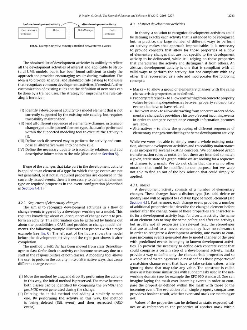
P. Mäder, O. Gotel / The Journal of Systems
OrderManager Order- printOrder()
OrderManager- printOrder()
Order
before development a ctivity after d evelopme nt a ctivi ty
ataitcba
(
iycti
4
crfamebc
astd
(
Fig. 6. Example activity: moving a method between two classes
The obtained list of development activities is unlikely to reflectll the development activities of interest and applicable to struc-ural UML models, but it has been found sufficient to study thepproach and provided encouraging results during evaluation. Thedea is to provide an initial and stabilized rule catalog to the usershat recognizes common development activities. If needed, furtherustomization of existing rules and the definition of new ones cane done by a trained user. The strategy for improving the rule cat-log is iterative:
(I) Identify a development activity to a model element that is notcurrently supported by the existing rule catalog, but requirestraceability maintenance.
(II) Find all different sequences of elementary changes, in terms ofchange type and impacted element type, that can be performedwithin the supported modeling tool to execute the activity in(I).
(III) Define each discovered way to perform the activity and com-pose all alternative ways into one new rule.
IV) Define the necessary update to traceability relations and adddescriptive information to the rule (discussed in Section 5).
If one of the changes that take part in the development activitys applied to an element of a type for which change events are notet generated, or if not all required properties are captured in theurrently issued events, then it is necessary to define that elementype or required properties in the event configuration (describedn Section 4.4.1).
.2.2. Sequences of elementary changesThe aim is to recognize development activities in a flow of
hange events triggered by a developer working on a model. Thisequires knowledge about valid sequences of change events to per-orm an activity. This information can be gathered by finding outbout the possibilities a CASE tool provides to change model ele-ents. The following example illustrates that process with a simple
xample (see Fig. 6). The left part of the figure shows the modelefore the development activity and the right part shows it afterompletion.
The method printOrder has been moved from class OrderMan-ger to class Order. Such an activity can become necessary due to ahift in the responsibilities of both classes. A modeling tool allowshe user to perform the activity in two alternative ways that causeifferent change events:
(I) Move the method by drag and drop. By performing the activityin this way, the initial method is preserved. The move betweenboth classes can be identified by comparing the preMOD andpostMOD event generated during the change.
II) Deleting the initial method and adding a similarly namedone. By performing the activity in this way, the methodis being deleted (DEL event) and then recreated (ADDevent).
and Software 85 (2012) 2205– 2227 2213
4.3. Abstract development activities
In theory, a solution to recognize development activities couldbe defining exactly each activity that is intended to be recognizedbut, in practice, the large number of different ways to performan activity makes that approach impracticable. It is necessaryto provide concepts that allow for those properties of a flowof elementary changes that are not specific to the developmentactivity to be delineated, while still relying on those propertiesthat characterize the activity and distinguish it from others. Anabstract development activity is one that is compliant with allvalid ways to perform the activity, but not compliant with anyother. It is represented as a rule and incorporates the followingconcepts:
• Masks – to allow a group of elementary changes with the samecharacteristic properties to be defined.
• Property references – to allow abstracting from concrete propertyvalues by defining dependencies between property values of twoevents that have to have related.
• The EventCache – to allow abstracting from concrete orders of ele-mentary changes by providing a history of recent incoming eventsin order to compare events once enough information becomesavailable.
• Alternatives – to allow the grouping of different sequences ofelementary changes constituting the same development activity.
While we were not able to simply reuse a whole existing nota-tion, abstract development activities and traceability maintenancerules incorporate several existing concepts. We considered graphtransformation rules as notation, but these are intended to matcha given, static state of a graph, while we are looking for a sequenceof changes to a graph. We do not claim that there is no othernotation that could be modified to our purpose, but we werenot able to find an out of the box solution that could simply beapplied.
4.3.1. MasksA development activity consists of a number of elementary
changes. These changes have a distinct type (i.e., add, delete ormodify) and will be applied to a certain type of model element (seeSection 4.1). Furthermore, each change event provides a numberof additional properties that describe the changed element beforeand/or after the change. Some of these properties are characteris-tic for a development activity (e.g., for a certain activity the nameof an element has to stay the same before and after the activity),but usually not all properties are relevant (e.g., the stereotypesthat are attached to a moved element may have no relevance).In order to recognize a development activity, one wants to com-pare incoming events generated due to model changes of the userwith predefined events belonging to known development activi-ties. To prevent the necessity to define each concrete event thatcould comprise a certain step of a development activity, masksprovide a way to define only the characteristic properties and soa whole set of matching events. A mask defines those properties ofa matching change event that have to take certain values, whileignoring those that may take any value. The construct is calledmask as it has some similarities with subnet masks used in the net-working domain (see for example the RFC 950 standard). One canimagine laying the mask over incoming events in order to com-pare the properties defined within the mask with those of theincoming event. The evaluation of all single property comparisons
provides a boolean result, whether event and mask are matching ornot.Values of the properties can be defined as static expected val-ues or as references to the properties of another mask within

2 stems
tetffoheiO
atetmbuas
4
teipncnr
oebetacwrp
brcttbmc(
e
4
ta
214 P. Mäder, O. Gotel / The Journal of Sy
he same development activity (see Section 4.3.2). Two prop-rties of an expected event have to be defined for each mask,he change type and the element type. This restriction resultsrom the necessity to find a compromise between abstractionrom concrete events in order to save effort for the definitionf rules and to keep the defined rules easily comprehensible byumans to allow their customization. The following shows anxample of a mask that matches with incoming change eventsndicating the deletion of a method named printOrder from a classrderManager:
DEL(type=‘method’; id=*; name=‘printOrder’;parent.type=‘class’; parent.id=*;parent.name=‘OrderManager’)
The * symbol is a wildcard that defines a property that can haveny value within an incoming event while still being compliant withhe mask. In the example, the id’s of the method and that of thenclosing class as well as applied stereotypes to the method mayake any concrete value in a compliant event. To be able to allow
ultiple valid values for one property, or to exclude certain values,oolean logic is supported for the definition of property values. Bysing boolean logic, it is possible to allow any but one value for
property (e.g., type=¡class’) or to allow for multiple values (e.g.,tereotype=‘use’ || ‘realize’).
.3.2. Property referencesMasks allow characteristic properties of an elementary change
o be defined. In most cases, this is not sufficient as a concretexpected value is not known at the time of rule definition. Whats known is the relation between elementary changes, for exam-le, that a property of one elementary change has to have or mustot have the same value as a property of another elementaryhange that participates in the same development activity (e.g., theame of the replacing element must be different from that beingeplaced).
The approach addresses this problem by allowing the definitionf the value within one mask as a reference to a value of a prop-rty within another mask. This means that the value is expected toe the same as or distinct from the value of the referenced prop-rty of a change event that will be assigned to a different mask ofhe same development activity. These references between masksllow elementary changes to be related to one another. Referencesonsist of an identifier of the mask and the name of the propertyithin that mask that they refer to. In order to be able to resolve
eferences, circular references between two or more masks must berevented.
The following example shows two masks with referencesetween them. These masks work together to help match aule. An event that matches mask 1 would be any that indi-ates that a method has been deleted from a class. An eventhat matches mask 2 would be any that informs about the addi-ion of a method with the same name as the method that haseen assigned to mask 1 (mask 2: name=1.name). Furthermore,ask 2 requires that the method has not been added to the same
lass that the one assigned to mask 1 has been deleted frommask 2: parent.id=!1.parent.id).
(mask 1) DEL(type=‘method’; id=*; name=*; par-nt.id=*;
parent.type=‘class’; parent.name=*)(mask 2) ADD(type=‘method’; id=*; name=1.name;
parent.id=!1.parent.id; parent.name=*;parent.type=‘class’)
.3.3. The EventCacheIdentifying a development activity requires comparing at least
wo states of a model, before and after a change. This means thatt least two masks have to be defined as a change sequence to
and Software 85 (2012) 2205– 2227
recognize a compound development activity. Such changesequences can often be carried out via various orders of underly-ing elementary changes. Referring back to the example of moving amethod, there is no difference in terms of the overarching applieddevelopment activity if the method is deleted first from the ini-tial class and added afterwards to the new class or vice versa. Thenumber of possible permutations is defined by the number of ele-mentary changes contributing to a development activity and isconstrained by the existence of elements (e.g., an element cannot bemodified or deleted before it has been created and the correspond-ing events in that case are not interchangeable). However, the orderin which a development activity is performed has no influence onthe characteristic properties of the triggered change events, whichmeans that they do not vary depending on the order in which adevelopment activity is performed.
This enables only one sequence of masks to be defined, indepen-dent of the order in which events belonging to an activity arrive. Theorder of the masks within the change sequence does not imply anyrequired order of the incoming events. Nevertheless, most maskswill be defined as dependent upon other masks by referencing val-ues of their properties, which means that it might not be possibleto compare a matching change event immediately after its arrivalif the mask in question has references to another mask that has notyet been assigned to an incoming event. To address this situation, anumber of past incoming events is held in an EventCache. The con-crete process of comparing events with masks has been discussedin Mäder et al. (2008b).
Having a set of past incoming events and a number of abstractactivity descriptions (defined as a set of masks) raises questionsabout when and how to start comparing them. As discussed before,references that one mask have to another can only be resolved if anevent has already been assigned to the referenced mask. To startthat mechanism, one mask within each change sequence is requiredthat must have no references. This mask is called the TriggerMaskand the assignment of an event to that mask triggers the recognitionprocess.
4.3.4. AlternativesTo address the issue of performing a development activity in
multiple ways, several change sequences can be grouped as onerule that is able to recognize the same overarching developmentactivity. The different change sequences performing the same activ-ity are called alternatives. Alternatives can be seen as a groupingof similar change sequences transforming an initial state of modelelements into the same final state.
4.4. Rules
All the concepts discussed in Section 4.3 have been incorpo-rated in the structure of rules and comprise a rule catalog. The rulesrecognize development activities and hold information about thenecessary traceability update after recognition.
As an example of a concrete rule, Listing 1 shows the rule torecognize the move of a method between two classes. The ruledefinition contains a name, description, and two alternative waysto perform the activity. The description is presented to the userupon recognition of the activity, in cases where user interaction isrequired. Numbers preceded by a percentage sign are placeholderscontaining concrete model element information at runtime. Alter-native 1 requires to delete the method from one class (mask T) andto add it to another class (mask 1). The characteristic properties ofthis change sequence are defined with mask 1, the added method
has to have the same name as the deleted one, it may not have thesame id as the deleted one and may not be added to the class it hasbeen deleted from. Alternative 2 requires to drag the method fromone class (mask T) and to drop it on another class (mask 1). The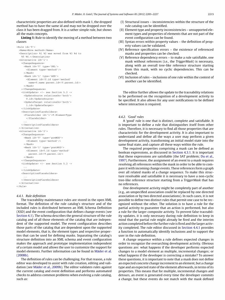
stems
cmca
c
<
<
4
fi(Scdtmtsmom(
edtcs
P. Mäder, O. Gotel / The Journal of Sy
haracteristic properties are also defined with mask 1, the droppedethod has to have the same id and may not be dropped over the
lass it has been dragged from. It is a rather simple rule, but showsll the main concepts.
Listing 1: Rule to identify the moving of a method between twolasses
Rule id=‘9’>
<Name>Move method</Name>
<Description> %1 %2 was moved from %3 %4 to
%5 %6.</Description>
<Alternative id=‘1’>
<ChangeSequence>
<Mask id=‘T’ type=‘DEL’>
<Element type=‘method’/>
</Mask>
<Mask id=‘1’ type=‘ADD’>
<Element id=!T.id type=‘method’
name=T.name parent.id=!T.parent.id/>
</Mask>
</ChangeSequence>
<LinkUpdate> <!– see Section 5.2 –>
<UpdateSource relationsOn=‘both’>
T.id</UpdateSource>
<UpdateTarget relationsOn=‘both’>
1.id</UpdateTarget>
</LinkUpdate>
<DescriptionPlaceholders>
<Placeholder id=‘1’>T.ElementType
</Placeholder>
. . .</DescriptionPlaceholders>
</Alternative>
<Alternative id=‘2’>
<ChangeSequence>
<Mask id=‘T’ type=‘preMOD’>
<Element type=‘method’/>
</Mask>
<Mask id=‘1’ type=‘postMOD’>
<Element id=T.id type=‘method’
parent.id=!T.parent.id/>
</Mask>
</ChangeSequence>
<LinkUpdate> <!– see Section 5.2 –>
. . .</LinkUpdate>
<DescriptionPlaceholders>
. . .</DescriptionPlaceholders>
</Alternative>
/Rule>
.4.1. Rule definitionThe traceability maintenance rules are stored in the open XML
ormat. The definition of the rule catalog’s structure and of thencluded rules is distributed between an XML Schema DefinitionXSD) and the event configuration that defines change events (seeection 4.1). The schema describes the general structure of the ruleatalog and of all those elements of the catalog that are indepen-ent of the supported model. The event configuration describeshose parts of the catalog that are dependent upon the supported
odel elements, that is, the element types and respective proper-ies that can be used for defining masks. Separating the catalog’structure definition into an XML schema and event configurationakes the approach and prototype implementation independent
f a certain model and allows the user to customize the support forodel elements. Further information can be found in Mäder et al.
2008b).The definition of rules can be challenging. For that reason, a rule
ditor was developed to assist with rule creation, editing and vali-
ation (see Mäder et al., 2009b). The editor validates rules againsthe current catalog and event definition and performs automatedhecks to address common problems when evolving a rule catalog,uch as:and Software 85 (2012) 2205– 2227 2215
(I) Structural issues – inconsistencies within the structure of therule catalog can be identified.
(II) Element type and property inconsistencies – unsupported ele-ment types and properties of elements that are not part of theevent configuration can be found.
(III) Syntax errors within property values – the definition of prop-erty values can be validated.
(IV) Reference specification errors – the existence of referencedmasks and properties can be checked.
(V) Reference dependency errors – to make a rule satisfiable, onemask without references (i.e., the TriggerMask) is necessary,along with an overall tree-like reference structure startingfrom this mask, with no cyclic dependencies. This can bechecked.
(VI) Inclusion of rules – inclusions of one rule within the context ofanother can be identified.
The editor further allows the update to the traceability relationsto be performed on the recognition of a development activity tobe specified. It also allows for any user notifications to be definedwhere interaction is required.
4.4.2. ‘Good’ rulesA ‘good’ rule is one that is distinct, complete and satisfiable. It
is important to define a rule that distinguishes itself from otherrules. Therefore, it is necessary to find all those properties that arecharacteristic for the development activity. It is also important tounderstand and define all the ways a user may perform a givendevelopment activity, transforming an initial model state into thesame final state, and capture all these ways within the rule.
The required properties comprising a mask can be defined asboolean expressions, as discussed in Section 4.3.1. It is importantthat these expressions are satisfiable (the SAT problem; Du et al.,1997). Furthermore, the assignment of an event to a mask requiresresolving all references within the mask in order to be able to com-pare it with incoming change events. These references form a graphover all related masks of a change sequence. To make this struc-ture resolvable and satisfiable it is necessary to have a non-cyclictree-like reference structure starting from a TriggerMask that hasno references.
One development activity might be completely part of another(e.g., an unspecified association could be replaced by one directedassociation or by two directed associations). In such cases, it is notpossible to define two distinct rules that permit one case to be rec-ognized without the other. The solution is to have a rule for thepartial activity to guarantee that an action is performed, but alsoa rule for the larger composite activity. To prevent false traceabil-ity updates, it is only necessary during rule definition to keep inmind that the partial rule might already be fired and the interimaction completed before the further rule is fired and the larger activ-ity completed. The rule editor discussed in Section 4.4.1 providesa function to automatically identify inclusions and to support theuser in the rule definition.
A change sequence within a rule defines expected changes inorder to recognize the overarching development activity. Obviousquestions are: what happens if the developer performs expectedchanges to a model element as multiple, incremental changes; orwhat happens if the developer is correcting a mistake? To answerthese questions, it is important to note that a mask does not definean expected concrete change increment to an element, but a change
type and an expected state of the element afterwards, in terms of itsproperties. This means that for multiple, incremental changes anddetours, an event is generated every time the developer commitsa change, but these events do not match with the mask defined
2 stems
ws
4
ms(tcbt2t2
4
iottuf
4
tnmmtentd
tcbccesmenc
ualaosa
4
bedlat
trace(s) on new element.• An existing node can be deleted from the graph. Traceability
216 P. Mäder, O. Gotel / The Journal of Sy
ithin the rule and so will be ignored until the event comes in thathows the element in the expected state.
.4.3. Rule applicationThe task of matching elementary changes with traceability
aintenance rules requires an effective rule engine. Such reactiveystems are built according to the Event Condition Action paradigmECA) (van Bemmel et al., 2004). This paradigm defines systems thatrigger an action after an incoming event has matched a definedondition. As this approach is not intended to react to a single event,ut to react to patterns over the event history, a much more sophis-icated rule engine with Complex Event Processing (CEP) (Luckham,002) was necessary. This has been developed as part of the proto-ype system that implements the approach (see Mäder et al., 2008b,009b).
.5. Critique of Phase 1
The quality of the proposed approach to development activ-ty recognition depends upon two aspects: (I) the completenessf the rule catalog in terms of defined development activities andhe ways in which they could be achieved; and (II) the quality ofhe defined rules, so the degree to which a rule correlates with thenderlying development activitiy. Both aspects are discussed in theollowing sections.
.5.1. Expression power of rulesIn this section we discuss the limitations of our technique in
erms of expression power. Our technique relies on the semi-formalature of the analyzed structural UML diagrams. That means knownodel element types and their properties, defined within the UMLeta-model. That information is used to relate elementary changes
o each other. Our masks allow using all these properties of modellements to definite development activities. Limitation of our tech-ology arises from whether the available properties are sufficiento define a cohesive activity that can certainly be recognized andistinguished from others.
We can state that the expressiveness was sufficient to define allhe discovered development activities during our initial study dis-ussed in Section 4.2.1. Nonetheless, there are activities that cannote recognized with sufficient certainty. As example, we are dis-ussing the splitting and merging of methods that are not currentlyovered by our rule catalog. Methods are elementary, non-dividablentities within a structural UML model and as such do not offerufficient properties for recognizing their splitting or merging auto-atically. As opposed to the splitting and merging of compound
ntities, e.g., classes, components, and packages, which is recog-ized by a move of child elements, e.g., methods, attributes, andlasses.
This limitation is acceptable as these are fine-grained activities,sually performed on the source code level and not within analysisnd design models. Our approach supports activities at the sameevel of granularity as the notation does. If we would extend ourpproach to development activities in source code, we could rec-gnize the splitting and merging of methods by observing moves ofource code parts between methods and so recognize the splittingnd merging of methods.
.5.2. Completeness of the rule catalogThrough experimentation, the current rule catalog appears to
e stable (as discussed in Section 6). However, it is not possible tonsure the completeness of all development activities in the catalog
ue to the semi-formal nature of UML models. The current cata-og can provide a common set of rules for the supported model,s the evaluation will show, but it is likely that it has to be fur-her enhanced and improved. It can also be necessary to customize
and Software 85 (2012) 2205– 2227
single rules to the specific needs of a developer (e.g., to supportdifferent ways of refining elements). In this context, an incompleterule catalog means fewer traceability relations are maintained inan automated manner than could be.
4.5.3. Quality of the rule catalogThe quality and correctness of the defined rules are very impor-
tant for the success of the proposed approach and will get evenmore important as the catalog expands. Issues that may arise canbe classified into two generic categories:
(I) False recognition – a rule fires in situations it is not intendedfor.
(II) Missing recognition – a rule does not fire in a situation whereit should.
Both problems can be caused by an issue that could be referredto as finding the right abstraction between rule and developmentactivity. If a rule is too abstract and does not constrain propertiessufficiently, then it will fire in those situations where the soughtdevelopment activity has not taken place, potentially leading tofalse changes to traceability relations. If properties are constrainedtoo much, a rule will not recognize the development activity inall the ways it can be performed, potentially leading to missingchanges to traceability relations. These issues cannot be foundby analyzing the rule catalog, but they can be examined by per-forming experiments and black-box tests with a given catalog. Amissing recognition can also be the result of syntax or reference fail-ures within the rule specification. A missing recognition might alsohappen due to unsatisfiable boolean expressions in the propertydefinition or due to unresolvable, circular dependencies betweenmasks. Both these issues are addressed by validation tests withinthe rule editor.
5. Traceability relation maintenance
This section describes Phase 2 of the approach and its underlyingconcepts.
5.1. Development activity types
Focusing on post-requirements traceability relations, eachrelated requirement spans a graph towards implementation arti-facts (e.g., analysis elements, design elements and test cases).The nodes of this graph represent related elements in the sameor different models, and the arcs represent traceability relationsbetween these elements. Each related requirement spans such atree. Fig. 7 depicts an example graph of two requirements andtheir related implementing artifacts (red and green highlighted).The graph also depicts possible changes to related elements andtheir impact on existing traceability relations (gray shaded). Thedirectionality of the arcs expresses dependence between relatedartifacts (see Section 2.1). Correlating to the development activitytypes discussed in Section 4.2, the following changes and associ-ated traceability updates to the graph are possible and depicted inthe figure:
• A new node can be added to the graph. Traceability update: create
update: remove trace(s) connected to deleted element.• An existing node can be replaced by another node. Traceability
update: restoration of all traceability relations of the replacedmodel element on the replacing element.
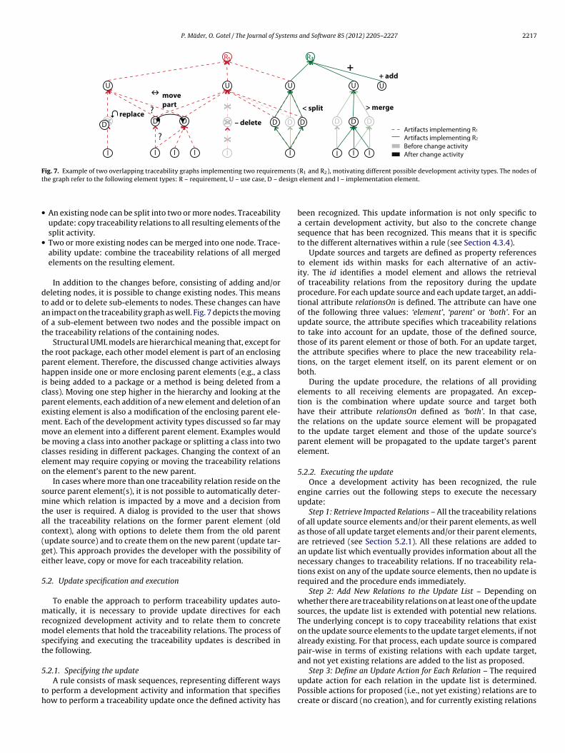
P. Mäder, O. Gotel / The Journal of Systems and Software 85 (2012) 2205– 2227 2217
+ add
> merge< split
– deleterepla ce
movepart
Artifa cts impleme nting R 1
Artifa cts impleme nting R 2
Before change a ctivi tyAfter change a ctivi ty
Fig. 7. Example of two overlapping traceability graphs implementing two requirements (R and R ), motivating different possible development activity types. The nodes oft esign
•
•
dtaot
tphicpemmbceo
smtac(ge
5
mrmst
5
th
he graph refer to the following element types: R – requirement, U – use case, D – d
An existing node can be split into two or more nodes. Traceabilityupdate: copy traceability relations to all resulting elements of thesplit activity.Two or more existing nodes can be merged into one node. Trace-ability update: combine the traceability relations of all mergedelements on the resulting element.
In addition to the changes before, consisting of adding and/oreleting nodes, it is possible to change existing nodes. This meanso add or to delete sub-elements to nodes. These changes can haven impact on the traceability graph as well. Fig. 7 depicts the movingf a sub-element between two nodes and the possible impact onhe traceability relations of the containing nodes.
Structural UML models are hierarchical meaning that, except forhe root package, each other model element is part of an enclosingarent element. Therefore, the discussed change activities alwaysappen inside one or more enclosing parent elements (e.g., a class
s being added to a package or a method is being deleted from alass). Moving one step higher in the hierarchy and looking at thearent elements, each addition of a new element and deletion of anxisting element is also a modification of the enclosing parent ele-ent. Each of the development activity types discussed so far mayove an element into a different parent element. Examples would
e moving a class into another package or splitting a class into twolasses residing in different packages. Changing the context of anlement may require copying or moving the traceability relationsn the element’s parent to the new parent.
In cases where more than one traceability relation reside on theource parent element(s), it is not possible to automatically deter-ine which relation is impacted by a move and a decision from
he user is required. A dialog is provided to the user that showsll the traceability relations on the former parent element (oldontext), along with options to delete them from the old parentupdate source) and to create them on the new parent (update tar-et). This approach provides the developer with the possibility ofither leave, copy or move for each traceability relation.
.2. Update specification and execution
To enable the approach to perform traceability updates auto-atically, it is necessary to provide update directives for each
ecognized development activity and to relate them to concreteodel elements that hold the traceability relations. The process of
pecifying and executing the traceability updates is described inhe following.
.2.1. Specifying the updateA rule consists of mask sequences, representing different ways
o perform a development activity and information that specifiesow to perform a traceability update once the defined activity has
1 2
element and I – implementation element.
been recognized. This update information is not only specific toa certain development activity, but also to the concrete changesequence that has been recognized. This means that it is specificto the different alternatives within a rule (see Section 4.3.4).
Update sources and targets are defined as property referencesto element ids within masks for each alternative of an activ-ity. The id identifies a model element and allows the retrievalof traceability relations from the repository during the updateprocedure. For each update source and each update target, an addi-tional attribute relationsOn is defined. The attribute can have oneof the following three values: ‘element’, ‘parent’ or ‘both’. For anupdate source, the attribute specifies which traceability relationsto take into account for an update, those of the defined source,those of its parent element or those of both. For an update target,the attribute specifies where to place the new traceability rela-tions, on the target element itself, on its parent element or onboth.
During the update procedure, the relations of all providingelements to all receiving elements are propagated. An excep-tion is the combination where update source and target bothhave their attribute relationsOn defined as ‘both’. In that case,the relations on the update source element will be propagatedto the update target element and those of the update source’sparent element will be propagated to the update target’s parentelement.
5.2.2. Executing the updateOnce a development activity has been recognized, the rule
engine carries out the following steps to execute the necessaryupdate:
Step 1: Retrieve Impacted Relations – All the traceability relationsof all update source elements and/or their parent elements, as wellas those of all update target elements and/or their parent elements,are retrieved (see Section 5.2.1). All these relations are added toan update list which eventually provides information about all thenecessary changes to traceability relations. If no traceability rela-tions exist on any of the update source elements, then no update isrequired and the procedure ends immediately.
Step 2: Add New Relations to the Update List – Depending onwhether there are traceability relations on at least one of the updatesources, the update list is extended with potential new relations.The underlying concept is to copy traceability relations that existon the update source elements to the update target elements, if notalready existing. For that process, each update source is comparedpair-wise in terms of existing relations with each update target,and not yet existing relations are added to the list as proposed.
Step 3: Define an Update Action for Each Relation – The requiredupdate action for each relation in the update list is determined.Possible actions for proposed (i.e., not yet existing) relations are tocreate or discard (no creation), and for currently existing relations

2 stems
ad
D
D
D
D
D
fir
5
odlpttmai
ufgpmfmFmsttcmowt
5
t
218 P. Mäder, O. Gotel / The Journal of Sy
re to stay (no change) or delete. The required update action isetermined according to the following directives:
1 The update action for relations on the update source(s) isdefined to stay if the source element still exists. It is defined todelete if the element has been removed during the developmentactivity.
2 For relations on the parent element of update source(s), theupdate action cannot be determined automatically in mostcases and the user is required to decide between stay and deletefor each relation. Optionally, for situations with exactly onerelation on the parent element, the action for this relation canbe defined to stay automatically.
3 Proposed relations on the update targets are defined to be cre-ated.
4 For proposed relations on the parent element of update tar-gets, no distinct action can be defined automatically and theuser has to decide between create and discard. Optionally, ifonly one relation was existing on the parent element of theupdate source, then this relation can be defined to be createdautomatically.
5 All existing relations of all update target(s) and its parent ele-ments are defined to stay. These relations are not impacted bythe development activity, but they are included in the updatelist to provide the whole context of an update during user inter-action.
Step 4: Execute the Update – In this step, all the actions definedor the traceability relations in the update list are transformednto commands for the traceability relation repository. The relationepository processes these commands and completes the update.
.2.3. Project-specific traceability maintenanceAn issue that has not been discussed so far is the customization
f updates according to the intended traceability for a project, asefined in the traceability information model. The specified cata-
og includes rules to recognize generic development activities withossible impact on traceability relations for a supported model. Fur-hermore, the updates within each rule are defined in a general wayo update impacted traceability relations on all update source ele-
ents participating in the development activity. The idea is to have general catalog not requiring customization for each new projectn order to reduce the effort of using the approach.
A problem that could arise is that traceability relations arepdated or created on elements that are not intended to be tracedor a given project. Even if a rule exists within the catalog and is trig-ered by a development activity of the developer, an update is onlyerformed if traceability relations exist on the update source ele-ents. If the type of the update source element is not to be traced
or the given project, then no relation should exist on it. Due toistakes of the developer or the tool, relations may exist anyway.
urthermore, there are rules defined within the catalog that copy orove impacted relations between different types of elements and
o could also create unintended relations. To avoid traceability rela-ions that would violate the current traceability information model,he traceability relation repository should validate any created orhanged traceability relation against the project’s traceability infor-ation model before performing the change. The customization
f allowed traceability relations for a project should only be doneithin the traceability information model so as to define a project’s
raceability in one place.
.3. Critique of Phase 2
The approach is intended to support the developer in the main-enance of traceability relations and to hence save tedious work.
and Software 85 (2012) 2205– 2227
Even where interaction is required on the update, the user onlyhas to make a few simple decisions instead of navigating throughrelated models and searching for impacted traceability relationsand their related elements manually.
Even where automated, it is important to inform the user aboutany automated changes to traceability relations. While the recogni-tion of development activities happens in the background and goesunnoticed, the traceability update may be perceived. Such an indi-cation helps the developer to understand the approach and allowsfor the validation of the development activity recognition and per-formed automated updates. The knowledge about missing updatesallows traceability to be maintained manually where needed, toprevent its decay. By recognizing incorrect or missing updates, ruleevolution is also possible.
6. Evaluation
This section describes an experiment that was undertaken toevaluate the approach with respect to the manual effort that canbe saved and quality that can be reached with the maintainedtraceability while implementing changes to a specific developmentproject. In the context of industrial use, there are two questions thatmatter when considering an automated solution for traceabilitymaintenance. An adopter wants to know how much effort and costcan be saved by the proposed solution and whether the result, themaintained traces, is at least of comparable quality to that resultingfrom manual maintenance. Eventually, even an automated mainte-nance solution with significant effort savings will only be adopted,if the overall costs of traceability within a development project areless than the expected benefits. This break-even point is individualfor each project and this overall analysis is not within the scope ofthis evaluation.
6.1. traceMAINTAINER prototype system
A prototype system called traceMAINTAINER has been imple-mented to help evaluate the approach. traceMAINTAINER worksin the background while a developer works on software devel-opment using structural UML diagrams. It generates changeevents for elementary model changes and recognizes develop-ment activities. Once a development activity has been recognized,traceMAINTAINER performs the necessary maintenance to impactedtraceability relations, with user interaction if necessary. Such userinteraction is basically the only situation where an everyday usersees the prototype system. Fig. 8 shows that dialog for the develop-ment activity of moving a method between two classes. It requiresthe user to decide between alternative ways of updating the trace-ability relations. For setting-up and customizing the recognitionand update process, the prototype system provides additional com-ponents that allow, for example, the editing and validation of rules.traceMAINTAINER is described more fully in Mäder et al. (2009b),Mäder et al. (2008c).
6.2. Industrial validation
We established a cooperation with Siemens in the Czech Repub-lic in order to get information about the usefulness of the approachin industrial practice. The cooperating group fulfilled all the precon-ditions for applying the approach in their projects (i.e., model-baseddevelopment using a UML modeling tool and having establishedtraceability relations). The leader of this group agreed to apply theapproach on two different projects over the course of one year.
This cooperation delivered valuable input for improving theapproach and insight into traceability practice within the particu-lar projects. Apart from technical feedback regarding improvementof the approach, we also received qualitative feedback on the

P. Mäder, O. Gotel / The Journal of Systems and Software 85 (2012) 2205– 2227 2219
2•1 «is linked»Order
+ printOrder() : void
OrderManager
«is linked»CreateOrder
0•1
«is linked»PrintOrder
0•1
«is linked»OrderHandling
1•0
«trace»
«trace»
«trace»
r inte
aaatbddb
d
6
atet
6
mbtt
tawiloictatw
Fig. 8. Semi-automated traceability update with use
pproach from practitioners at Siemens who were piloting thepproach. Practitioners told us that they felt supported by thepproach in maintaining traceability. Furthermore, they likedhe fact that the approach was working automatically in theackground, in most cases without user interaction. However, itelivered no measurable data. The reason was that the model underevelopment was not accessible to people outside Siemens, so noaseline was available against which to compare results.
The controlled experiment described in the next section waseveloped in order to get measurable results.
.3. Experimental set-up
We designed a controlled experiment in order to validate ourpproach. The experiment has one independent variable (the use ofraceMAINTAINER) and two treatments (tM, no − tM). The aim of thexperiment was to answer the two research questions described inhe following.
.3.1. Research question 1: manual effortDoes use of the approach reduce the manual effort necessary for
aintaining traceability relations? While no manual effort woulde a desirable target, evidence is sought of a reduction greater thanhe time necessary to configure and learn how to interact withraceMAINTAINER to make use of the approach worthwhile.
Measures: The manual effort for traceability maintenance referso the time the developer spends on this task. It comprises: thinkingbout the maintenance task (including recognizing it); navigatingithin the models; and performing the required changes. Measur-
ng the time taken for these sub-tasks is problematic given theack of access to thought processes and the inter-weaved naturef the sub-tasks with the modeling tasks that cause the traceabil-ty maintenance to be required. Attempting to gain data about theomplete traceability maintenance effort would require the user
o provide additional information that allows distinguishing trace-bility maintenance from modeling. The intention of the selectedasks was to capture realistic data in a full modeling scenarioithout drawing the attention of our participants exclusively toraction after moving a method between two classes
traceability maintenance. As an indicator of effort, the number ofperformed changes to the set of traceability relations was recorded(manual changes for both treatments and automated changes forthe tM treatment), along with the time spent responding to trace-MAINTAINER dialogs. The dependent variables recorded in order toanswer research question 1 were:nM+ Number of manually added relations to the link-set (the set of
traceability relations).nM− Number of manually deleted relations from the link-set.nA+ Number of automated added relations to the link-set.nA− Number of automated deleted relations from the link-set.nUI Number of user interactions with traceMAINTAINER before
maintaining the link-set.tUI Elapsed time between opening an interaction dialog and the user’s
response to it.
For subjects of the no − tM treatment, only nM+ and nM− are avail-able and were recorded, while for subjects of the tM treatment allvariables were recorded.
Metrics: The number of manual changes to relations is the sourcefor estimating the time and costs the developer spends on main-taining traceability. To be able to compare the number of manualchanges among subjects of both treatments, the following metriccompares the manual changes (cumulated added and deleted rela-tions) for both treatments as a relative percentage of changes forthe tM treatment:
rel. nM(tM) = nM(tM) − nM(no − tM)nM(no − tM)
· 100 (1)
where
nM = nM+ + nM− (2)
The rel . nM(tM) metric does not take into account that manuallyadding a relation usually consumes more time then manually delet-ing a relation. Furthermore, the time that the user spends to reacton a traceMAINTAINER update dialog tUI is not taken into account.The time to undertake a manual change could not be measured
precisely as discussed before.For those reasons, we conducted a small experiment withten subjects. Each subject was required to create ten new tracesbetween given model elements, to remove ten existing traces, and

2220 P. Mäder, O. Gotel / The Journal of Systems and Software 85 (2012) 2205– 2227
Table 1Tested hypotheses to answer research question 1.
tec
t
Todrpoem
r
p
1rtg(tie5h
6
eru
iwiFalietetbwbtwt
���
ow
Table 2Tested hypotheses to answer research question 2.
Variable Null hypothesis H0 Alternative hypothesis Ha
model relations and no requirements/implementation relations).The relations are always directed from the dependent to indepen-dent model. Use cases and classes have to be related by at leastone relation. Attributes, methods, components and packages can
Table 3Project models, diagrams and elements.
Requirementsmodel
Designmodel
Implementationmodel
DiagramsActivity 7 – –Class 1 6 6Package – 1 1State charts 3 – –Sequence – 5 –Use case 3 – –Elements
Variable Null hypothesis H0 Alternative hypothesis Ha
nM nM(tM) ≥ nM(no − tM) nM(tM) < nM(no − tM)
o respond to ten user interactions. Based on the results of thatxperiment, the comparable effort of the three direct measures wasorrelated as follows:
M+ ≈ 2 · tM− ≈ 2 · tUI. (3)
he correlation says that a user, on average, spends half the timen deleting a relation and on reacting to a traceMAINTAINER updateialog than she/he spends on creating a new relation. Using thiselation to weigh the number of manual changes nM+ and nM−erformed by subjects of both treatments, and using the numberf user interactions nUI for the tM group, an approximate relativeffort rel . E(tM) for the tM treatment in relation to the no − tM treat-ent can be computed as follows:
el. E(tM) = nM+(tM) + 0.5 · nM−(tM) + 0.5 · nUI(tM)nM+(no − tM) + 0.5 · nM−(no − tM)
(4)
Both metrics have been computed for the gathered data and arerovided in Sections 6.4 and 6.5.
Hypothesis: The null hypothesis H0 regarding research question was that the number of manual changes to the set of traceabilityelations nM performed by the experimental group tM is greaterhan or equal to the number of changes performed by the controlroup no − tM (see Table 1). We expect that the use of the approachindependent variable) will reduce the number of manual changeso the set of traceability relations nM (dependent variable) – thiss the alternative hypothesis Ha. If the data gathered during thexperiment supports the null hypothesis H0 with a probability of% or less then this hypothesis would be rejected and the alternativeypothesis Ha considered.
.3.2. Research question 2: maintenance qualityDo the traceability updates performed by the approach, in coop-
ration with the user where required, result in a set of traceabilityelations of comparable or better quality to those maintained man-ally?
Measures: An agreed baseline is required to determine the qual-ty of a set of traceability relations. Here, the baseline refers to what
ould have been the correct and required changes to the traceabil-ty relations following the changes performed to the related models.or this experiment, the baseline was individual for each subjectnd her/his individual solution to the modeling tasks. These base-ines were determined after the experiment by the experimentersn a labor intensive procedure. The guidelines for determiningach baseline were the traceability information model and theask description given to the subjects. In cases of ambiguity, twoxperimenters decided about the correctness or incorrectness of araceability relation. The experiment and baseline were preparedy the first author of the paper and by a graduate student, bothith multi year experience in requirements engineering, model-
ased development, and requirements traceability. According tohe baseline, three types of changes to the traceability relationsere distinguished and represent the dependent variables cap-
ured to answer research question 2:
c Changes that have been performed correctly according to the baseline.i Changes that have been performed incorrectly.
Missing changes that have not been performed.
mMetrics: To be able to compare the correctness and completenessf the changes among the subjects and treatments, two metricsere computed that are commonly used to evaluate approaches
QP QP(tM) ≤ QP(no − tM) QP(tM) > QP(no − tM)QR QR(tM) ≤ QR(no − tM) QR(tM) > QR(no − tM)
dealing with uncertainty in recognition processes: precision andrecall. Precision relates correct changes to all performed changesand informs the correctness of performed changes:
QP = �c
�c + �i(5)
Recall relates correct changes to all required changes and informsthe completeness of performed changes:
QR = �c
�c + �m(6)
Hypothesis: The null hypothesis H0 regarding research question2 was that the values of the metrics Precision QP and Recall QR
for the tM treatment are less than or equal to those of the no − tMtreatment (see Table 2). The alternative hypothesis Ha states thatthe precision and recall of changes are greater for the tM treatment.
6.3.3. Development projectThe experiment was conducted on models for a mail-order
system described as UML diagrams. These models described a com-pleted project implemented in Java. The project had initially beendeveloped as seminar work (Dommasch and Duhme, 2004) and wasreverse engineered and enhanced into a complete model-baseddevelopment project for the Enterprise Architect modeling tool.The project artifacts included models on three levels of abstraction:requirements, design and implementation. All diagrams of interestare shown in the appendices of Mäder (2009). The models pro-vided information to a level of detail that one would expect at theend of the design phase, including use case diagrams, interactiondiagrams and class diagrams. The diagrams and their elements arelisted in Table 3. Please note that only the class and package dia-grams were expected to be maintained by the subjects. Behavioraldiagrams were not related by traces and, accordingly, were onlyavailable to provide the best possible information about the sys-tem to the subject. The set of traceability relations for this projectrelates the three models and consisted of 214 traceability relations.The initial linking was undertaken according to a traceability infor-mation model for the project that was also provided to the subjectsof the experiment. This stated that only relations between require-ments/design and design/implementation are valid (i.e., no intra
Attributes 23 73 150Classes 15 41 63Methods – 124 280Packages – 5 5

stems
bf
6
etumaaeaidttfiot
1
2
3
a
6
wnacbt
6
ltaudam
6
tbaa(adaar
P. Mäder, O. Gotel / The Journal of Sy
e related to any other element, as long as the preceding rules areollowed.
.3.4. Modeling tasksThree maintenance tasks were to be performed on these mod-
ls, in a fixed order, adding new features of practical valuehat would impact every part of the system. Although thenderlying source code was made available within the imple-entation model, the tasks only required changes to the design
nd implementation models. Based on a pilot study with fourdditional master students, covering a spread of developmentxperience, it was estimated that it would take 2–3 h to completell the tasks. Subjects were permitted to perform the tasks accord-ng to their ideas and experiences to capture a realistic spread ofifferent solutions to the same problem. This means that the solu-ions would not be comparable per se. The correctness analysisherefore required inspecting each individual model in order tond out about correct, incorrect and missing changes to the setf traceability relations. The subjects had to perform the followingasks:
. Enhance the system’s functionality to distinguish private andbusiness customers and also to handle foreign suppliers.
. Extract the two layers, view and data, of the system’s three-layerarchitecture into separate components.
. Enhance the system’s functionality to handle additional productgroups (e.g., print media and consumer electronics) and providefunctionality to categorize products according to content cate-gories.
The task descriptions and the questionnaires are available in theppendices of Mäder (2009).
.3.5. SubjectsThe subjects comprised 16 computer science students with a
ide range of experience in UML and model-based software engi-eering. All the students were taking a course on software qualitynd were either in the 4th or 5th year of their diploma (Mastersomparable). The subjects were partitioned into two groups of 8,ased upon prior experience, to distribute expertise equally acrosshe two treatments.
.3.6. Data gatheringData were gathered via three questionnaires. For both groups, a
og file was created by traceMAINTAINER containing all the elemen-ary changes performed by the subject, all changes to the link-setnd information about how often the subject navigated the modelssing traceability relations. For the tM group, a log of all recognizedevelopment activities, the user decisions on interactions and allutomatically performed traceability updates was also created. Theodels of all the subjects were available for the analysis.
.4. Results
Fig. 9(a) depicts the number of manual changes nM to theraceability relations for each single task and across all tasks foroth treatments as a box plot. The information is also displayed,long with additional statistical measures, in Table 4, as vari-ble nM+ + nM−. The table shows, for each variable, the minimalmin), median, arithmetic mean and maximal (max) value sep-rated according task and treatment. Furthermore, the standard
eviation (sd) of the values within one treatment and the percent-ge difference between the mean values (% diff) of both treatmentsre depicted where appropriate. Fig. 9(b) depicts the number ofesponses to the traceMAINTAINER update dialog for each task andand Software 85 (2012) 2205– 2227 2221
across all tasks for the tM treatment. This information is also dis-played in Table 4 as variable nUI. Fig. 9(c) and (d) depicts themeasured precision QP and recall QR values for each task and acrossall tasks for both treatments as box plots. This information andadditional statistical measures are also displayed in Table 4.
Univariate analyses of the dependent variables were performedto test the hypotheses, both individually for each task and acrossall tasks. For all the dependent variables nM, nA, nUI, QP and QR,two-sample t-tests were performed. The preconditions of the t-test,normality and equality of variances, were given for the measureddata. For normality, we tested with the one-sample Kolmogorov-Smirnov procedure and for the equality of variances we tested withthe Levene’s test. The level of significance for the hypotheses testswas set to ̨ = 0.05. P-values are provided in the t-test column ofTable 4. One subject from each group had to be excluded from theanalysis because they did not provide a minimal solution to eachmodeling task. This precondition was required in order to compareresults between all subjects.
6.5. Discussion
Within this section, the results presented in Section 6.4 are dis-cussed separately in relation to the research questions.
6.5.1. Research question 1: manual effortWhen examining the number of manual changes nM to the link-
set over the three tasks, the tM group performed far fewer changes(rel . nM(tM) =− 82 %) than the no − tM group (see Table 4). This dif-ference is statistically significant (p − value < 0.01). The result issimilar for each single task.
Comparing the overall number of changes for both treatments(both manual and automated for the tM treatment), the figuresshow that the no − tM group performed only half as many changes(nM(no − tM) = 36.3) than the tM group’s combined total of manualand automated changes (nM(tM) + nA(tM) = 6.6 + 59.6 = 66.2) for alltasks. The explanation for that behavior is that traceMAINTAINERrecognizes small incremental change activities and updates trace-ability relations immediately (in the background) after recognition.This means that the changes reflect each detour of the developer, incontrast to manual maintenance where the update is typically per-formed after completing the whole task. Although the developer’sstrategy results in fewer changes and seems to be the better one, itis important to note that a developer is able to recognize semanticrelations between model elements and to validate traceability rela-tions at any time. In contrast, our automated approach discussedhere has to follow each incremental change in order to updaterelations. The time to undertake a manual change could not be mea-sured precisely because it is not clear when the developer startsto think about a change task. This effort was estimated indirectlyvia the manually created relations, the manually deleted relationsand the user interactions. This measure provides an approxima-tion to the saved effort by using traceMAINTAINER, as shown inTable 4. The values show that, across all tasks, the subjects of thetM treatment spent only rel . E(tM) = 29% as much manual efforton maintaining traceability as the subjects of the no − tM treat-ment. The higher value of rel . E(tM) = 52% for task 2 results fromthe nature of the task that required a large number of move activ-ities with impact on traceability relations of the parent elements(see Section 6.3.4). The traceability updates associated with theseactivities required a relatively large number of interactions with theuser nUI = 6.2 that, in combination with the low number of man-ual changes (nM(tM) = 0.8 vs . nM(no − tM) = 7.7), led to the higher
relative effort of rel . E(tM) = 52% for task 2.Overall, a decrease of 71% manual effort for the maintenanceof traceability relations for the discussed experiment is seenas positive regarding the goal to reduce the manual effort for

2222 P. Mäder, O. Gotel / The Journal of Systems and Software 85 (2012) 2205– 2227
all 1 2 3
010
2030
4050
60
Task
Num
ber
of m
anua
l cha
nges
all 1 2 3
010
2030
4050
60no−tMtM
(a) Ma nual change s for bot h treatme nts
all 1 2 3
05
1015
Task
Num
ber
of u
ser i
nter
actio
ns (t
M)
(b) Use r interaction s for tM treatm ent
all 1 2 3
020
4060
8010
0
Task
Prec
isio
n [%
]
all 1 2 3
020
4060
8010
0
no−tMtM
(c) Preci sion for bot h treatme nts
all 1 2 3
020
4060
8010
0
Task
Reca
ll [%
]
all 1 2 3
020
4060
8010
0
no−tMtM
(d) Reca ll fo r bot h treatm ents
F nts (bb
mtae)fwwrrwu
6
asatpohr
ig. 9. Results of the experiment as box plots. (a) Manual changes for both treatmeoth treatments.
aintaining traceability relations, especially as the subjects of theM treatment spent only a few minutes on their training sessionbout the approach. To find out whether this decrease is largenough to facilitate a broader use of traceability and such (semi-
automated maintenance in practice remains to be evaluated inuture industrial studies. After the experiment, all but one subjectorking with traceMAINTAINER stated that they felt comfortableith the technology after a short time and that they did not expe-
ience conflicts or disturbance by the automated updates. Theemaining subject said that it was sometimes difficult to knowhether an automated update would occur or whether a manualpdate was called for.
.5.2. Research question 2: maintenance qualityThe computed precision QP and recall QR provide information
bout the correctness and completeness of changes to the link-et (see Table 4). The results show that the tM group reached
precision QP> 95 % for all tasks, with a low standard devia-ion (sd(QP) = 2.5–6.5%). This value is 21% higher than the average
recision value of the no − tM group across all tasks. Valuesf precision lower than 100% indicate that incorrect changesave been performed to the link-set. We analyzed these incor-ect changes and found that among all the changes performed) User interactions for tM treatment (c) Precision for both treatments (d) Recall for
by traceMAINTAINER, no incorrect ones were found. All incor-rect changes within the tM group were manual changes of thesubject. Please note that our approach automates only the main-tenance of existing traceability, but the general nature of ourtasks required also the addition of completely new elements andaccordingly the creation of new traces. Precision and recall mea-sure the overall quality of all link changes performed during theexperiment.
Recall of changes measures whether all necessary changeshave been performed. Across both groups and all tasks, not allrequired link changes were performed (all recall values lower than100%) showing that subjects of both treatments missed addition-ally required manual link changes. The average values per taskare more diverse than the precision results. For tasks 1 and 3, theno − tM group reached higher values of recall (6 and 11%) than thetM group. An analysis of the results showed that all our rules firedas intended and indicates that subjects working with our auto-mated approach relied on that support and missed more of theadditionally required manual changes. We wanted to explore the
capabilities of the approach without putting the focus of subjectstoo much on our approach. Accordingly, we did not explain all con-cepts of the approach, nor how and when automated updates areto be expected. That approach might have actually influenced the
P. Mäder, O. Gotel / The Journal of Systems and Software 85 (2012) 2205– 2227 2223
Table 4Number of changes to traceability relations and number of user interactions during traceability update (upper table) and precision and recall of changes to traceabilityrelations (lower table).
Task Variable Treatment Min Median Mean Max sd % diff t-Test Rel. effort
1
nM+ + nM− no − tM 6 21 18.6 32 9.5 −87% <0.01 18%tM 0 3 2.4 4 1.8
nA+ + nA− tM 0 38 36.2 65 23.9nUI tM 0 1 2.0 5 2.0
2
nM+ + nM− no − tM 2 6 7.7 16 4.9 −90% 0.01 52%tM 0 0 0.8 4 1.8
nA+ + nA− tM 8 14 13.0 17 3.3nUI tM 2 4 6.2 14 4.9
3
nM+ + nM− no − tM 5 10 10.0 16 4.7 −66% 0.04 33%tM 0 0 3.4 9 4.7
nA+ + nA− tM 2 7 12.4 37 14.0nUI tM 0 1 0.8 2 0.8
All
nM+ + nM− no − tM 22 34 36.3 62 12.8 −82% <0.01 29%tM 3 5 6.6 12 3.8
nA+ + nA− tM 19 51 59.6 114 34.7nUI tM 4 9 9.0 15 4.1
Task Variable Treatment Min Median Mean Max sd % diff t-Test
1
QP no − tM 0.0 95.7 78.9 100.0 36.5 21% 0.34tM 87.8 100.0 95.7 100.0 6.0
QR no − tM 0.0 96.3 78.0 100.0 36.3 −6% 0.82tM 20.0 74.4 73.3 100.0 32.7
2
QP no − tM 15.4 100.0 83.3 100.0 31.0 19% 0.29tM 94.4 100.0 98.9 100.0 2.5
QR no − tM 14.3 50.0 59.5 100.0 35.3 51% 0.10tM 70.0 100.0 90.0 100.0 14.1
3
QP no − tM 0.0 100.0 81.6 100.0 37.5 17% 0.44tM 85.7 100.0 95.6 100.0 6.5
QR no − tM 0.0 83.3 76.2 100.0 35.8 −11% 0.67tM 25.0 66.7 67.8 98.6 27.3
All
QP no − tM 27.3 90.3 79.5 100.0 25.7 21% 0.19tM 90.3 96.1 95.9 100.0 4.3
QR no − tM 23.1 80.6 71.3 100.0 27.6 11% 0.6178
qemawtg(etprre
mivt
6
(sspeW
tM 51.1 80.0
uality results of the tM group, as they did not exactly know when toxpect automated updates and when they were required to updateanually. What we learned from that finding is that users require
good tutorial on when to expect automated maintenance andhen they are required to create relations manually. For task 2,
he no − tM group had a recall of only 59.5% versus 90% in the tMroup. That task required large structural changes to the modelsee Section 6.3.4) with high impact on the traceability relations oflements and their parent elements. A possible explanation is thathe subjects working manually were not able to remember all there-existing traceability relations before their changes in order toe-establish them after the changes. This explanation would cor-elate with results from the inspection of the models after thexperiment.
However, any differences between the two treatments for botheasures are not statistically significant (compare column t-test
n Table 4). Nevertheless, the aim of the approach was to pro-ide maintenance quality that is comparable to that reached byhe developer manually.
.5.3. Dependence on the subjects’ experienceIn addition to the previous analyses, an analysis of variances
ANOVA) exploring the combined effect of the treatment and theubjects’ experience on the number of manual changes to the link-
et nM, the precision of changes QP and the recall of changes QR waserformed. The aim was to find out whether the subjects’ experi-nce had also a significant impact on the results of the experiment.e performed separate ANOVAs for each dependent variable and.8 99.3 19.0
for each task as well as across all tasks. Table 5 shows the p-values ofall these analyses. The values within the confidence level of ̨ = 0.05are marked in bold.
The results show that the number of manual changes depends,for each single task and across all tasks, upon the treatment (see p-values in the treatment row of Table 5). This finding has alreadybeen discussed in Section 6.5.1 and there is no significant dif-ference in precision and recall depending on the treatment (seeSection 6.5.2). Regarding the dependence of the three variables(nM, QP and QR) upon the experience of the subject (see p-valuesin the experience row of Table 5), the impact was not signifi-cant, except for the recall of task 1. For task 1, the experience ofthe subject had a significant impact on the recall QR the subjectsreached with their changes. This means that more experiencedsubjects reached a better recall QR of their changes to traceabil-ity relations than less experienced subjects here. This correlationhas only been found for task 1 and a p-value of 0.05 shows onlya weak significance. Overall, the analyses show that the experi-ence of the subjects had almost no impact on the results (numberof manual changes to the link-set nM, precision of changes QP andrecall of changes QR). To be able to generalize these findings, addi-tional experiments with a larger population of subjects would berequired.
6.6. Threats to validity
This section discusses what is considered to be the most impor-tant threats to the validity of the discussed experiment.

2224 P. Mäder, O. Gotel / The Journal of Systems and Software 85 (2012) 2205– 2227
Table 5Analysis of variance (ANOVA) of the treatment and the experience of the subject on the dependent variables.
Dependent variable
Independent variable Manual changes nM Precision QP Recall QR
All 1 2 3 All 1 2 3 All 1 2 3
Treatment 0.00 0.00 0.02 0.05 0.17 0.32 0.32 0.42 0.58 0.79 0.12 0.65.17
6
topymSabsewswtmddmnl
6
smcethestidbukg
6
tetuttjwsae
Experience 0.25 0.11 0.57 0.67 0
.6.1. External validityThe issue of external validity concerns whether a causal rela-
ionship holds over variations in persons, settings, treatments andutcomes that were either in the experiment or not. From a taskerspective, the reported experiment is realistic. Students (futureoung professionals) were working on a real project, using com-ercial tools and implementing demanding tasks. We used the
parx Enterprise Architect modeling tool, which is commerciallyvailable and has a very large (>100k), globally distributed userase. A brief survey on the tracing functionality of UML toolshowed that it is comparable among common modeling tools. Nev-rtheless, it is hard to draw conclusions to a wider populationithout more studies. The results reflect more a tendency that
hows the potential of the approach. There are threats associatedith the short time the subjects spent on the experiment (3 h) given
he task complexity. However, it was not the focus of the experi-ent to set trivial tasks with obvious changes. A high-level task
escription enabled a variety of ways to solve the problem, butemanded effort to analyze and evaluate the data (55k lines of logessages and 16 different models). Without sophisticated tech-
iques, it would be complicated to run an experiment lasting muchonger.
.6.2. Internal validityInternal validity is concerned with establishing a causal relation-
hip, here between the use of traceMAINTAINER and the number ofanual changes to the link-set. Based upon prior experience, we
reated two groups with equal distribution regarding the experi-nce factor. One group was assigned to the tM treatment, the othero the no − tM treatment, creating a balanced design. In order toave comparable results among participants, it was necessary toxclude one subjects from each treatment after the experimentince they did not solve the modeling tasks completely, makingheir results not comparable. The potential influence of the facil-tators was addressed by providing an initial briefing and taskescription in written form only. The difference in the materialetween groups was marginal, the addition being how to react on aser interaction for the tM group. None of the subjects had any priornowledge of the approach nor did they know the experimentaloals.
.6.3. Construct validityConstruct validity refers to having established correct opera-
ional measures for the constructs being studied. To investigate theffect of the approach on the effort for maintaining traceability rela-ions after the evolution of related UML models it is necessary tose the UML as intended. The UML offers an open set of descriptionechniques with many ways to apply them. In this experiment, sixypes of diagram at different levels of detail were used, the sub-ects had state-of-the-art education in UML development and a
idely distributed CASE tool was used. The debriefing interviewhowed that almost all the subjects became familiar with the toolfter their prior tutorial. The examination of the resulting mod-ls showed that, except for two cases (explained before), all the
0.21 0.78 0.23 0.12 0.05 0.68 0.14
subjects were able to edit and evolve the UML models in a mannercomparable to industrial practice.
To investigate the effort for maintaining traceability relations,we decided for an indirect measure, i.e., counting the number ofmanual link changes and user interactions. To emulate a realisticsetting we demanded model maintenance tasks, not traceabilitymaintenance tasks, so we were unable to distinguish the time spenton traceability maintenance from the remaining time for solving atask. The disadvantage of that decision is that we cannot computeconcrete time differences based upon our data, only the relativedifferences in effort. We found that trade-off acceptable, thoughfurther studies could focus on concrete time differences.
To investigate the correctness of the changes to the link-set, themain problem with comparing traceability is the lack of an agreedstandard. Therefore, a traceability information model was providedto give guidance on how to establish traceability for the project. Theinitial creation of traceability relations was done according to themodel and the subjects were required to do likewise. In order togain comparable results, further restrictions were made as to theminimal number and direction of relations (see Section 6.3).
6.6.4. ReliabilityIt is expected that replications of the experiment should offer
results similar to those presented in this section. Of course, con-crete measured values will differ from those presented here as theyare specific to the subjects, but the underlying trends and implica-tions should remain unchanged as the analysis showed that theexperience of the subject had little influence on the results. Fur-thermore, pilot studies executed with two additional developers ontwo projects (described in Mäder et al., 2008a,b), showed similarresults and so support the findings.
7. Critical review and future work
While seeking evaluation partners for the approach, two inter-esting perspectives arose when talking with practitioners fromSiemens who were responsible for traceability within develop-ment projects. After an explanation of the approach, one individualreplied: “I do not think that I like an automated solution for thissensible task. I want people to think about their changes againwhile maintaining traceability.” A second individual replied: “thatis exactly the solution I was waiting for, it can save us a lot ofwork”. This reflects the fact that the decision for or against a (semi-)automated approach to traceability maintenance is individual. Thedeveloped approach can save tedious and error-prone work, butit should not be seen as a solution that makes the maintenance oftraceability relations something that the developer does not haveto think about anymore, as there may be intrinsic value in thatactivity. Potential limitations of the approach are examined in thisconcluding section, with obvious implications for future research.
7.1. Assumptions of the approach
Section 3.2 lists the assumptions that were made while devel-oping the approach. These assumptions refer to the development

stems
pUtir(tum(tt
7
maciio
7
ciocwtanbnbwfisdtir
7
taisftbr
7
omwmr
P. Mäder, O. Gotel / The Journal of Sy
rocess of a project and require model-based development, using aML modeling tool and the application of traceability in accordance
o a traceability information model. Except for the traceabilitynformation model, this is exactly the scenario that has beeneported by nine of the ten interviewed companies in a survey paperMäder et al., 2009c). The extension of the approach to additionalypes of diagrams and models remains a future task. Regardingse of a traceability information model, a major problem is theissing support for such definitions within common CASE tools
Ritze, 2008). For the evaluation of the approach, the support of araceability information model has been integrated into the proto-ype tool.
.2. Predefined rule catalog
A limitation of the approach is that only predefined develop-ent activities can be recognized and these are unlikely to reflect
ll possible development approaches, so it will be necessary toustomize and extend the rule catalog. In order to address thisssue, a rule editor is provided with sophisticated checks to val-date changes to rules. Nevertheless, this task remains a manualne.
.3. Scope of and threats to empirical studies
It is a future exercise to gain more statistical data on theost/benefit trade-off of the approach, costs in terms of customiz-ng and extending the rules, and benefits in terms of the time savedn manual maintenance across all projects using the rules. The dis-ussed experiment showed a substantive saving of manual efforthile using the existing rule catalog. Unfortunately, no informa-
ion is available about how much work of a development projectccurately relates to evolving related models and triggering theecessity for traceability maintenance. Such information can onlye gained by performing studies in real projects. There is clearly aeed for empirical work here and gaining that information shoulde a future research topic for the traceability community. Whilee cannot provide concrete figures, we can refer to the often-usedgures that claim that 70% of a development’s budget is spent onoftware maintenance (Glass, 2002). Where this is a model-basedevelopment process, we assume a considerable amount of efforthat is spent on changing and updating models. Without concretenformation, it is problematic to understand how much effort iseally saved for a project, despite best approximations.
.4. Semantic correctness of relations
The approach maintains existing traceability relations whetherhey are semantically correct or not. It is not possible to find outbout the correctness of relations or even to improve their qual-ty via the approach. This means that it requires a reasonableet of initial traceability relations to make the approach use-ul. For projects where this initial quality cannot be guaranteed,he manual maintenance of traceability relations might be theetter choice, allowing the developer to correct problems whenecognized.
.5. Uncertainty in the recognition process
There are several points of uncertainty in the process for rec-gnizing development activities that might lead to incorrect or
issing traceability updates. Missing rules and missing alternativesithin rules can lead to unrecognized development activities andissing updates, while insufficiently defined rules can lead to theecognition of development activities that have not been performed
and Software 85 (2012) 2205– 2227 2225
and so to incorrect traceability updates. The validation function-ality within the rule editor supports the identification of certainproblems within a rule definition, but a proportion of ensuring thecorrectness and completeness of the rule catalog remains manualwork.
7.6. Future work
One goal during the development of the approach was toreduce the manual effort involved in the maintenance of trace-ability relations as much as possible. There are two areas thatstill require manual work: selecting impacted traceability relationsduring a semi-automated update; and customizing and extend-ing the rules. Regarding the selection of impacted traceabilityrelations during a semi-automated update, the visualization andanimation of the impacted element, along with all related ele-ments before and after the update could support the user in her/hisdecision. Regarding the definition of rules, the existing rule edi-tor could be extended by functionality that allows new rules to bedefined semi-automatically by observing a developer performingchange activities in situ while using a rule recorder. Furthermore,a more intuitive, preferably visual, representation of rules wouldbe desirable in order to facilitate an easier rule definition andcustomization by users. Finally, the extension and improvementof the rule catalog is a continuous effort that requires ongoingattention as more results from industrial usage become avail-able. For example, whether there should be a default update foreach deletion or addition to a composition or inheritance struc-ture remains an open issue and we plan to work on it in thefuture.
While the support of structural UML diagrams addresses a com-mon scenario in industry (Mäder et al., 2009c), it would be desirableto extend the approach to other kinds of development model. Thenecessary preconditions would be models described in a semi-formal language with a defined meta-model and sufficient elementproperties to allow for the identification of meaningful develop-ment activities. For example, the following types of diagram wouldmeet these preconditions to a certain extent: behavioral UML dia-grams, feature diagrams, Mathworks SimulinkTM diagrams and NILabViewTM diagrams.
The information that is gained about performed developmentactivities by the user is currently only used to enable the mainte-nance of traceability, but this information could also support otheractivities within the development process. It could, for example,be used to generate change logs for version control systems andcould also support the checking of correctness of the performeddevelopment activities.
The propagation of changes was another goal of the approachand has been incorporated into the recognition and update pro-cess. Nevertheless, it was not the main focus of this work and amore sophisticated and selective procedure based on the availableinformation about the change and its type, following the work ofCleland-Huang et al. (2003), could be possible.
The requirements traceability problem (Gotel and Finkelstein,1994) has many facets and it is unlikely that there will ever be asingle approach that solves the whole problem, but much work hasbeen done on this topic over the past decade that provides promis-ing approaches to partial aspects. A major goal for the traceabilitycommunity should clearly be the integration of these techniquesin order to provide a solution for the whole traceability life cycleof a project. Two examples illustrate the advantages an integra-tion of existing approaches with the one discussed in this paper
could offer. First, the integration with approaches that supportthe initial creation of traceability relations would allow exist-ing projects to retain their investment in traceability by ongoing(semi-) automated maintenance of the generated relations. Second,
2 stems
btacim
smtitn
A
ipwatTA
R
A
A
A
A
A
C
C
C
D
D
D
E
E
F
F
G
226 P. Mäder, O. Gotel / The Journal of Sy
y integrating keyword matching techniques it would be possibleo provide more support for the developer in creating new trace-bility relations as a project evolves. A dialog could provide possibleounterparts for new traceability relations of an element, accord-ng to the traceability information model, ranked using keyword
atching techniques.Another more technical issue of integration relates to the tooling
cenario within larger projects. Different artifacts of the develop-ent process are often held in different tools and the support for
raceability between these tools varies (Mäder et al., 2009c). Thisntegration seems to be a precondition for the extended use ofraceability in larger industrial projects and thus for its mainte-ance.
cknowledgements
The authors thank Tobias Kuschke and Christian Kittler formplementing the prototype, Johannes Langguth for his work inreparing and analyzing the experiment, and all the students whoere involved in the experiment. Furthermore, the authors would
lso like to thank the anonymous reviewers of an earlier version ofhis paper for their useful suggestions for improving the final paper.his research was part funded by DFG grant Ph49/7-1 and by theustrian Science Fund (FWF): M1268-N23.
eferences
izenbud-Reshef, N., Nolan, B.T.,Rubin, J., Shaham-Gafni, Y., 2006. Model traceabil-ity. IBM Systems Journal 45 (3), 515–526, ISSN 0018-8670, http://dx.doi.org/10.1147/sj.453.0515.
lexander, I., 2002. Toward automatic traceability in industrial practice. In: Pro-ceedings of 1st International Workshop on Traceability in Emerging Forms ofSoftware Engineering (TEFSE02), Edinburgh, UK, pp. 26-31, http://www.soi.city.ac.uk/zisman/WSTPapers/Alexander.pdf.
ntoniol, G., Canfora, G., Casazza, G., Lucia, A.D., Merlo, E., 2002. Recovering trace-ability links between code and documentation. IEEE Transactions on SoftwareEngineering 28 (10), 970–983, ISSN 0098-5589, http://www.computer.org:80/tse/ts2002/e0970abs.htm.
rkley, P., Riddle, S., 2005. Overcoming the traceability benefit problem. In: Proceed-ings 13th International Requirements Engineering Conference, IEEE ComputerSociety, pp. 385–389, ISBN 0-7695-2425-7.
rlow. J., Neustadt, I., 2005. UML 2 and the Unified Process: Practical Object-OrientedAnalysis and Design, second edn. Addison-Wesley, ISBN 0-321-32127-8.
leland-Huang, J., Chang, C.K., Ge, Y., 2002. Supporting event based traceabil-ity through high-level recognition of change events. In: Annual InternationalComputer Software and Applications Conference (COMPSAC02), IEEE ComputerSociety, pp. 595–602, ISBN 0-769-51727-7, http://doi.ieeecomputersociety.org/10.1109/CMPSAC.2002.1045069.
leland-Huang, J., Chang, C.K., Christensen, M.J., 2003. Event-based trace-ability for managing evolutionary change. IEEE Transactions on SoftwareEngineering 29 (9), 796–810, ISSN 0098-5589, http://csdl.computer.org/comp/trans/ts/2003/09/e0796abs.htm.
oleman, D., 1994. Object-Oriented Development: The Fusion Method. Prentice-Hall, ISBN 0-131-01040-9.
ömges, R., Pohl, K., 1998. Adapting tracability environments to project-specificneeds. Communications of the ACM 41 (12), 54–62, 0001-0782.
ommasch, C., Duhme, D., 2004. Versandhandel: Hausarbeit in Objektorien-tierte Analyse und Design. Tech. Rep., http://www.christian-dommasch.de/downloads/versand/versand-dokumentation.pdf.
u, D., Gu, J., Pardalos, P.M. (Eds.), 1997. Satisfiability Problem: Theory and Appli-cations, vol. 35 of DIMACS Series in Discrete Mathematics and TheoreticalComputer Science. American Mathematical Society, ISBN 0-821-80479-0.
gyed, A., Grünbacher, P., Heindl, M., Biffl, S., 2007. Value-based requirementstraceability: lessons learned. In: Proceedings 15th International RequirementsEngineering Conference (RE07), pp. 115–118, ISSN 1090-705X.
ngels, G., Heckel, R., Küster, J.M., Groenewegen, L., 2002. Consistency-preservingmodel evolution through transformations. In: Proceedings 5th InternationalConference UML 2002 – The Unified Modeling Language. Model Engineering,Languages, Concepts, and Tools, vol. 2460 of Lecture Notes in Computer Science.Springer, Dresden, Germany, ISBN 3-540-44254-5, pp. 212-226.
inkelstein, A.C.W., Gabbay, D.M., Hunter, A., Kramer, J., Nuseibeh, B., 1994. Inconsis-tency handling in multiperspective specifications. IEEE Transactions on Software
Engineering 20 (8), 569–578, ISSN 0098-5589.owler, M., 1999. Refactoring: Improving the Design of Existing Code. Addison-Wesley, ISBN 0-201-48567-2.
lass, R.L., 2002. Facts and Fallacies of Software Engineering. Addison-Wesley,Boston, MA.
and Software 85 (2012) 2205– 2227
Gotel, O.C.Z., Finkelstein, A.C.W., 1994. An analysis of the requirements traceabilityproblem. In: Proceedings of the First International Conference on RequirementsEngineering (ICRE94), IEEE Computer Society, Colorado Springs, CO, pp. 94-101,ISBN 0-8186-5480-5.
Hayes, J.H., Dekhtyar, A., Osborne, J., 2003. Improving requirements tracing viainformation retrieval. In: Procerdings of 11th IEEE International RequiermentsEngineering Conference (RE03), IEEE Computer Society, pp. 138-148, ISBN 0-7695-1980-6, doi:10.1109/ICRE.2003.1232745.
Hnatkowska, B., Huzar, Z., Kuzniarz, L., Tuzinkiewicz, L., 2003. Refinement rela-tionship between collaborations. In: Proceedings Workshop on ConsistencyProblems in UML-based Software Development, UML’03, IEEE Computer Society,San Francisco, USA, pp. 51–57.
Huzar, Z., Kuzniarz, L., Reggio, G., Sourrouille, J.-L., 2004. Consistency problems inUML-based software development. In: Nunes, N.J., Selic, B., da Silva, A.R., Álvarez,J.A.T. (Eds.), UML Satellite Activities, vol. 3297 of Lecture Notes in ComputerScience. Springer, pp. 1–12, ISBN 3-540-25081-6.
Jacobson, I., Rumbaugh, J., Booch, G., 1999. The Unified Software DevelopmentProcess, Object Technology Series. Addison-Wesley, Reading, MA, ISBN 0-201-57169-2.
Kruchten, P., 2000. Rational Unified Process: An Introduction. Addison-Wesley,Reading, MA, ISBN 0-201-70710-1.
Lano, K., 2005. Advanced Systems Design With Java, UML and MDA. ElsevierButterworth-Heinemann, Amsterdam, The Netherlands, ISBN 0-750-66496-7.
Lucia, A.D., Oliveto, R., Tortora, G., 2008. IR-based traceability recovery processes:an empirical comparison of one-shot and incremental processes. In: 23rdIEEE/ACM International Conference on Automated Software Engineering (ASE2008), 15–19 September 2008, L’Aquila, Italy, IEEE Computer Society, pp. 39-48,ISBN 978-1-4244-2776-5, doi:10.1109/ASE.2008.14.
Luckham, D., 2002. The Power of Events: An Introduction to Complex Event Process-ing in Distributed Enterprise Systems. Addison-Wesley Professional, Reading,MA, ISBN 0-201-72789-7.
Mäder, P., Gotel, O., Philippow, I., 2008a. Rule-based maintenance of post-requirements traceability relations. In: Proceedings of 16th InternationalRequirements Engineering Conference (RE’08), Barcelona, Spain, pp. 23–32, ISSN1090-705X.
Mäder, P., Gotel, O., Philippow, I., 2008b. Enabling automated traceabilitymaintenance by recognizing development activities applied to models. In: Pro-ceedings of 23rd International Conference on Automated Software Engineering(ASE2008), L’Aquila, Italy.
Mäder, P., Gotel, O., Kuschke, T.I., 2008c. Philippow traceMaintainer – automatedtraceability maintenance. In: Proceedings of 16th International RequirementsEngineering Conference (RE’08), Barcelona, Spain, pp. 329–330.
Mäder, P., Gotel, O., Philippow, I., 2009a. Enabling automated traceability main-tenance through the upkeep of traceability relations. In: Proceedings 5thEuropean Conference on Model-Driven Architecture Foundations and Applica-tions (ECMDA2009), Enschede, Netherlands.
Mäder, P., Gotel, O., Philippow, I., 2009b. Semi-automated traceability maintenance:an architectural overview of traceMAINTAINER. In: Proceedings 5th ECMDATraceability Workshop (ECMDA-TW 2009). In conjunction with the 5th Euro-pean Conference on Model-Driven Architecture Foundations and Applications(ECMDA2009), Enschede, Netherlands.
Mäder, P., Gotel, O., Philippow, I., 2009c. Motivation matters in the traceabilitytrenches. In: Proceedings of 17th International Requirements Engineering Con-ference (RE’09), Atlanta, Georgia, USA.
Mäder, P., Gotel, O., Philippow, I., 2009d. Getting back to basics: promoting theuse of a traceability information model in practice. In: Proc. 5th Int’l Work-shop on Traceability in Emerging Forms of Software Engineering (TEFSE2009),Vancouver, Canada.
Mäder, P., 2009. Rule-based maintenance of post-requirements traceability. Ph.D.thesis, Technische Universität Ilmenau.
Maletic, J.I., Collard, M.L., Simoes, B., 2005. An XML based approach to supportthe evolution of model-to-model traceability links. In: Proceedings of 3rdInternational Workshop on Traceability in Emerging Forms of Software Engi-neering TEFSE’05, ACM, New York, NY, USA, pp. 67–72, ISBN 1-59593-243-7,http://doi.acm.org/10.1145/1107656.1107671.
Marcus, A., Maletic, J.I., 2003. Recovering documentation-to-source-code trace-ability links using latent semantic indexing. In: Proceedings of the 25thInternational Conference on Software Engineering (ICSE03), IEEE Com-puter Society, Piscataway, NJ, pp. 125-137, http://computer.org/proceedings/icse/1877/18770125abs.htm.
Mens, T., van der Straeten, R., Simmonds, J., 2005. A framework for managing consis-tency of evolving UML models. In: Yang, H. (Ed.), Software Evolution with UMLand XML. IGI Publishing, Hershey, PA, USA, pp. 1–30, ISBN 1-591-40462-2.
Murta, L.G.P., van der Hoek, A., Werner, C.M.L., 2006. ArchTrace: policy-based sup-port for managing evolving architecture-to-implementation traceability links.In: 21st IEEE/ACM International Conference on Automated Software Engineer-ing, ASE ’06, pp. 135–144, doi:10.1109/ASE.2006.16.
Murta, L.G.P., van der Hoek, A., Werner, C.M.L., 2008. Continuous andautomated evolution of architecture-to-implementation traceability links.Automated Software Engineering Journal 15 (1), 75–107, ISSN 0928-8910,http://dx.doi.org/10.1007/s10515-007-0020-6.
OMG, 2003. MDA Guide Version 1.0.1. Object Management Group (OMG), Framing-ham, MA, http://www.omg.org/mda,omg/2003-06-01.
OMG, 2008. OMG System Modeling Language (OMG SysML) Version 1.1. ObjectManagement Group OMG, Framingham, MA, http://www.omg.org/spec/SysML/1.1,formal/2008-11-01.

stems
O
P
R
R
R
S
S
S
v
W
P. Mäder, O. Gotel / The Journal of Sy
MG, 2010. OMG Unified Modeling Language Specification (OMG UML)Version 2.3. Object Management Group (OMG), Framingham, MA,http://www.omg.org/spec/UML/2.3/.
inheiro, F.A.C., 2004. Requirements traceability. In: Leite, J.C.S.P., Doorn, J. (Eds.),Perspectives on Software Requirements. Kluwer Academic Publishers, TheNetherlands, pp. 91–113, ISBN 1-402-07625-8.
itze, M., 2008. Comparison of the Traceability Functionality of CASE-Tools. Tech.Rep., Technical University of Ilmenau, Ilmenau, Germany.
oyce, W.W., 1987. Managing the development of large software systems: conceptsand techniques. Reprinted in: Proceedings of the 9th international conferenceon Software Engineering ICSE ’87. IEEE Computer Society Press, Los Alamitos,CA, USA, pp. 328–338, ISBN 0-89791-216-0.
ussek, L., 2004. OpenQuasar development of open source components with the aidof quasar. In: Dadam, P., Reichert, M. (Eds.), INFORMATIK 2004 – GI Jahrestagung,vol. 2. GI, pp. 488–492, ISBN 3-885-79380-6.
hen, W., Lu, Y., Low, W.L., 2003. Extending the UML metamodel to support softwarerefinement. In: Proceedings of the Workshop on Consistency Problems in UML-Based Software Development. In conjunction with UML2002, IEEE ComputerSociety, San Francisco, USA, pp. 35–42.
iedersleben, J., 2004. Moderne Software-Architektur. Dpunkt-Verlag, ISBN 3-898-64292-5.
panoudakis, G., Zisman, A., Pérez-Mi nana, E., Krause, P., 2004. Rule-basedgeneration of requirements traceability relations. Journal of Systems andSoftware 72 (2), 105–127, ISSN 0164-1212, http://dx.doi.org/10.1016/S0164-1212(03)00242-5.
an Bemmel, J., Dockhorn, P., Widya, I., 2004. Paradigm: Event-driven Comput-ing, White paper TI/RS/2004/051. Lucent Technologies, CTIT, https://doc.telin.nl/dscgi/ds.py/Get/File-48190.
eilkiens, T., 2006. Systems Engineering mit SysML/UML. Dpunkt-Verlag, ISBN 3-898-64409-X.
and Software 85 (2012) 2205– 2227 2227
Dr. Patrick Mäder received a Diploma degree in industrialengineering and a Ph.D. degree (Distinction) in computerscience from the Ilmenau University of Technology in2003 and 2009, respectively. He worked as a consul-tant for the EXTESSY AG, Wolfsburg between 2003 and2005. Currently, he is a postdoctoral fellow at the Insti-tute for Systems Engineering and Automation (SEA) ofthe Johannes Kepler University, Linz. Dr. Mäder also hasan active collaboration with the Software and Require-ments Engineering Center at DePaul University, Chicago.His research interests include topics related to softwareengineering, with a focus on requirements traceability,and object-oriented analysis and design.
Dr. Orlena (Olly) Gotel has been active in the area of trace-ability for over 20 years and received a Ph.D. on the topicfrom Imperial College, University of London, in 1995. Dr.Gotel has published widely on different aspects of thetraceability problem and is currently an Officer of theCenter of Excellence for Software Traceability, where sheis coordinating the Grand Challenges of Traceability andworking on its Body of Knowledge. In addition to aca-demic research and teaching positions in the UK (OxfordUniversity, City University, University College London)and the US (Pace University), Dr. Gotel has held senior
positions within the UK defense industry working on Sys-tems Requirements Engineering. Dr. Gotel received a B.Sc.(Hons) in Computer Science from the University of Warwick in 1989 and a M.Sc. (Dis-tinction) in Advanced Methods in Computer Science from the University of Londonin 1990.