Embed Size (px)
Citation preview

Institut fürTechnische Informatik undKommunikationsnetze
Pascal Gamper
Towards automated exploit signaturegeneration using honeypots
Master Thesis MA-2007-09March 2007 to September 2007
Tutor: Bernhard TellenbachCo-Tutor: Daniela BrauckhoffSupervisor: Prof. Bernhard Plattner

2
Acknowledgement
This master thesis would not have been possible without the support of many people. Theauthor wishes to express his gratitude to his tutor, Bernhard Tellenbach who was abundantlyhelpful and offered invaluable assistance, support and guidance. Furthermore, special thanksgo to the co-tutor Daniela Brauckhoff and the other members of the Communication SystemGroup (CSG), ETH Zurich, especially to Prof. Dr. Bernhard Plattner. The trip to Amsterdam wasawesome!Special thanks also to my classmates; Daniel Koller and Stefan Keller for sharing premises andnumerous hours playing foosball.

3
Abstract
Intrusion detection systems normally use some kind of signatures to identify attacks. Thesesignatures are manually created by experts in most cases. Nowadays a trend to more complexand fast spreading attacks can be observed and computer worms spread itself over the wholeworld within minutes. This is possible because vulnerabilities are known to the public just a fewhours before the first exploit is available or sometimes even disclosed by the publication of ex-ploit code. Attacks exploiting such a kind of vulnerability are called zero-day exploits. Zero-dayexploits such as the Slammer worm render the manual signature generation useless for thoseattacks. The automated signature generation addresses this problem. It attempts to automati-cally identify malicious network traffic or software code in order to generate a specific signaturefor it.This thesis is part of the EU project NoAH that aims at developing an automated signaturegeneration mechanism that is based on attack alert information originating from a network ofhoneypots. A framework for tracking the connection state and decoding protocol-field informa-tion of application-level protocols provides additional knowledge for the signature generation.In this thesis, we extended the framework with a plugin for the FTP protocol and did a redesignof its structure in favour of ease of use and extensibility. A signature generator for the Snortsignature format has been implemented that uses both information from the honeypot networkand application state information. It uses an external library for full protocol-field knowledge. Theresulting signatures are able to protect server applications from buffer overflows if triggered byabusing a single protocol field. The false-positives rate for these signatures is almost zero sincethey capture the vulnerability characteristics of the detected attacks.

4

Contents
1 Introduction 151.1 The trinity of trouble . . . . . . . . . . . . . . . . . . . . . . . . . . . . . . . . . . 151.2 Intrusion prevention . . . . . . . . . . . . . . . . . . . . . . . . . . . . . . . . . . 151.3 Situation in the Internet . . . . . . . . . . . . . . . . . . . . . . . . . . . . . . . . 161.4 The Network of Affined Honeypots (NoAH) . . . . . . . . . . . . . . . . . . . . . 171.5 Problem statement . . . . . . . . . . . . . . . . . . . . . . . . . . . . . . . . . . . 17
1.5.1 Application plugin for the tracker framework . . . . . . . . . . . . . . . . . 171.5.2 Signature Generation Mechanism . . . . . . . . . . . . . . . . . . . . . . 17
1.6 Structure of the Report . . . . . . . . . . . . . . . . . . . . . . . . . . . . . . . . . 18
2 Current state and Setup of the NoAH project 192.1 NoAH architecture overview . . . . . . . . . . . . . . . . . . . . . . . . . . . . . . 192.2 Components related to this work . . . . . . . . . . . . . . . . . . . . . . . . . . . 202.3 Containment system Argos . . . . . . . . . . . . . . . . . . . . . . . . . . . . . . 202.4 The tracker framework at a glance . . . . . . . . . . . . . . . . . . . . . . . . . . 21
3 Related Work 233.1 Content-based signatures . . . . . . . . . . . . . . . . . . . . . . . . . . . . . . . 23
3.1.1 Honeycomb . . . . . . . . . . . . . . . . . . . . . . . . . . . . . . . . . . . 243.1.2 Polygraph . . . . . . . . . . . . . . . . . . . . . . . . . . . . . . . . . . . . 243.1.3 Earlybird . . . . . . . . . . . . . . . . . . . . . . . . . . . . . . . . . . . . 243.1.4 Autograph . . . . . . . . . . . . . . . . . . . . . . . . . . . . . . . . . . . . 253.1.5 TaintCheck . . . . . . . . . . . . . . . . . . . . . . . . . . . . . . . . . . . 25
3.2 Flexible content-based signatures . . . . . . . . . . . . . . . . . . . . . . . . . . 253.2.1 PADS . . . . . . . . . . . . . . . . . . . . . . . . . . . . . . . . . . . . . . 253.2.2 PAYL . . . . . . . . . . . . . . . . . . . . . . . . . . . . . . . . . . . . . . 26
3.3 Context and semantics aware signatures . . . . . . . . . . . . . . . . . . . . . . 263.3.1 Nemean . . . . . . . . . . . . . . . . . . . . . . . . . . . . . . . . . . . . . 263.3.2 COVERS . . . . . . . . . . . . . . . . . . . . . . . . . . . . . . . . . . . . 273.3.3 Polymorphic Worm Detection using structural Information of Executables 27
3.4 Other approaches . . . . . . . . . . . . . . . . . . . . . . . . . . . . . . . . . . . 273.4.1 DOME . . . . . . . . . . . . . . . . . . . . . . . . . . . . . . . . . . . . . . 273.4.2 Paid . . . . . . . . . . . . . . . . . . . . . . . . . . . . . . . . . . . . . . . 283.4.3 HoneyStat . . . . . . . . . . . . . . . . . . . . . . . . . . . . . . . . . . . . 283.4.4 Vigilante . . . . . . . . . . . . . . . . . . . . . . . . . . . . . . . . . . . . . 28
4 Application Protocol Plugin 294.1 Requirements . . . . . . . . . . . . . . . . . . . . . . . . . . . . . . . . . . . . . . 294.2 Exploit survey and Protocol Evaluation . . . . . . . . . . . . . . . . . . . . . . . . 294.3 The File Transfer Protocol (FTP) . . . . . . . . . . . . . . . . . . . . . . . . . . . 304.4 The Garbage Collector Plugin . . . . . . . . . . . . . . . . . . . . . . . . . . . . . 31
4.4.1 Class SynchronizedMap . . . . . . . . . . . . . . . . . . . . . . . . . . . . 314.5 The FTP Plugin . . . . . . . . . . . . . . . . . . . . . . . . . . . . . . . . . . . . . 33
4.5.1 Deriving a state machine for connection state observation . . . . . . . . . 334.5.2 The plugin design . . . . . . . . . . . . . . . . . . . . . . . . . . . . . . . 35
4.6 Evaluation . . . . . . . . . . . . . . . . . . . . . . . . . . . . . . . . . . . . . . . . 364.6.1 Tracking states . . . . . . . . . . . . . . . . . . . . . . . . . . . . . . . . . 36
5
6 CONTENTS
4.6.2 Measuring performance . . . . . . . . . . . . . . . . . . . . . . . . . . . . 37
5 Signature Generator 395.1 Requirements . . . . . . . . . . . . . . . . . . . . . . . . . . . . . . . . . . . . . . 395.2 Signature format evaluation . . . . . . . . . . . . . . . . . . . . . . . . . . . . . . 405.3 Architecture . . . . . . . . . . . . . . . . . . . . . . . . . . . . . . . . . . . . . . . 40
5.3.1 Extracting alert information . . . . . . . . . . . . . . . . . . . . . . . . . . 405.3.2 Archiving signature information . . . . . . . . . . . . . . . . . . . . . . . . 415.3.3 Demonstrating signature capabilities . . . . . . . . . . . . . . . . . . . . . 425.3.4 Attack replaying . . . . . . . . . . . . . . . . . . . . . . . . . . . . . . . . 43
5.4 A signature generation mechanism (SGM) . . . . . . . . . . . . . . . . . . . . . . 445.5 Evaluation . . . . . . . . . . . . . . . . . . . . . . . . . . . . . . . . . . . . . . . . 45
6 A more generic approach for signature generation and state tracking 476.1 Observations . . . . . . . . . . . . . . . . . . . . . . . . . . . . . . . . . . . . . . 476.2 Survey . . . . . . . . . . . . . . . . . . . . . . . . . . . . . . . . . . . . . . . . . . 486.3 Protocol knowledge . . . . . . . . . . . . . . . . . . . . . . . . . . . . . . . . . . 486.4 The NetBee framework . . . . . . . . . . . . . . . . . . . . . . . . . . . . . . . . 49
6.4.1 Network Virtual Machine (NetVM) . . . . . . . . . . . . . . . . . . . . . . 506.4.2 Network Protocols Description Language (NetPDL) . . . . . . . . . . . . 506.4.3 Packet Details Markup Language (PDML) . . . . . . . . . . . . . . . . . . 506.4.4 Usage of the NetBee library . . . . . . . . . . . . . . . . . . . . . . . . . . 51
6.5 Protocol state automaton . . . . . . . . . . . . . . . . . . . . . . . . . . . . . . . 516.5.1 Architecture . . . . . . . . . . . . . . . . . . . . . . . . . . . . . . . . . . . 516.5.2 Specifying protocol automata . . . . . . . . . . . . . . . . . . . . . . . . . 536.5.3 Proposal for a timeout extension . . . . . . . . . . . . . . . . . . . . . . . 536.5.4 Proposal for a framework for protocol state tracking and packet replaying 54
6.6 Synthesis of network packets on application-level . . . . . . . . . . . . . . . . . . 54
7 Refactoring the Signature Generator 557.1 Experiences with Signature Generation . . . . . . . . . . . . . . . . . . . . . . . 557.2 Integrating NetBee . . . . . . . . . . . . . . . . . . . . . . . . . . . . . . . . . . . 567.3 Flexible configuration . . . . . . . . . . . . . . . . . . . . . . . . . . . . . . . . . . 567.4 Architecture . . . . . . . . . . . . . . . . . . . . . . . . . . . . . . . . . . . . . . . 567.5 Supported signatures . . . . . . . . . . . . . . . . . . . . . . . . . . . . . . . . . 587.6 Evaluation . . . . . . . . . . . . . . . . . . . . . . . . . . . . . . . . . . . . . . . . 59
7.6.1 Measuring signature generation performance . . . . . . . . . . . . . . . . 59
8 Conclusions and Outlook 618.1 Results . . . . . . . . . . . . . . . . . . . . . . . . . . . . . . . . . . . . . . . . . 618.2 Conclusions . . . . . . . . . . . . . . . . . . . . . . . . . . . . . . . . . . . . . . . 618.3 Outlook . . . . . . . . . . . . . . . . . . . . . . . . . . . . . . . . . . . . . . . . . 62
A NoAH core components: Extraction and Processing of attack information 63A.1 Initial attack information . . . . . . . . . . . . . . . . . . . . . . . . . . . . . . . . 63A.2 Current state of attack information extraction . . . . . . . . . . . . . . . . . . . . 64
B Glossary 67
C The original tracker framework 71C.1 Component overview . . . . . . . . . . . . . . . . . . . . . . . . . . . . . . . . . . 71C.2 Components and their algorithms . . . . . . . . . . . . . . . . . . . . . . . . . . . 72
D Techniques in Signature Generation Mechanisms 77D.1 Byte-Frequency Distribution (BFD) . . . . . . . . . . . . . . . . . . . . . . . . . . 77D.2 Longest Common Substring (LCS) problem . . . . . . . . . . . . . . . . . . . . . 77D.3 Longest Common Subsequence (LCSeq) problem . . . . . . . . . . . . . . . . . 77D.4 N-Gram analysis . . . . . . . . . . . . . . . . . . . . . . . . . . . . . . . . . . . . 77
D.4.1 Z-score . . . . . . . . . . . . . . . . . . . . . . . . . . . . . . . . . . . . . 78D.4.2 Dice coefficient . . . . . . . . . . . . . . . . . . . . . . . . . . . . . . . . . 78

CONTENTS 7
D.5 Expectation-Maximization (EM) algorithm . . . . . . . . . . . . . . . . . . . . . . 78D.6 Clustering . . . . . . . . . . . . . . . . . . . . . . . . . . . . . . . . . . . . . . . . 78
D.6.1 Hierarchical clustering . . . . . . . . . . . . . . . . . . . . . . . . . . . . . 78D.7 Rabin fingerprint . . . . . . . . . . . . . . . . . . . . . . . . . . . . . . . . . . . . 79D.8 Bayes law . . . . . . . . . . . . . . . . . . . . . . . . . . . . . . . . . . . . . . . . 79D.9 Content-based Payload Partitioning . . . . . . . . . . . . . . . . . . . . . . . . . 79
E Signature examples 81E.1 Honeycomb signature . . . . . . . . . . . . . . . . . . . . . . . . . . . . . . . . . 81E.2 Earlybird signature . . . . . . . . . . . . . . . . . . . . . . . . . . . . . . . . . . . 81E.3 COVERS signature . . . . . . . . . . . . . . . . . . . . . . . . . . . . . . . . . . 82E.4 Vigilante signature . . . . . . . . . . . . . . . . . . . . . . . . . . . . . . . . . . . 82
F Installation manual for the application state tracker fra mework 83F.1 The tracker framework . . . . . . . . . . . . . . . . . . . . . . . . . . . . . . . . . 83
F.1.1 Installing the tracker framework . . . . . . . . . . . . . . . . . . . . . . . . 83F.1.2 Configuration of the tracker framework . . . . . . . . . . . . . . . . . . . . 84
F.2 Qemu, Argos and the Interface . . . . . . . . . . . . . . . . . . . . . . . . . . . . 84F.2.1 Qemu . . . . . . . . . . . . . . . . . . . . . . . . . . . . . . . . . . . . . . 84F.2.2 Argos . . . . . . . . . . . . . . . . . . . . . . . . . . . . . . . . . . . . . . 85F.2.3 Networking . . . . . . . . . . . . . . . . . . . . . . . . . . . . . . . . . . . 85F.2.4 Tracker interface . . . . . . . . . . . . . . . . . . . . . . . . . . . . . . . . 86
F.3 Putting the Pieces Together . . . . . . . . . . . . . . . . . . . . . . . . . . . . . . 87F.4 Ready-to-use Scripts . . . . . . . . . . . . . . . . . . . . . . . . . . . . . . . . . . 87
F.4.1 Qemu-ifup . . . . . . . . . . . . . . . . . . . . . . . . . . . . . . . . . . . . 87F.4.2 Qemu-ifdown . . . . . . . . . . . . . . . . . . . . . . . . . . . . . . . . . . 88F.4.3 Start-argos . . . . . . . . . . . . . . . . . . . . . . . . . . . . . . . . . . . 88
G Signature Database 89
H TODOs 93

8 CONTENTS

List of Figures
1.1 The spread of the Internet worm code red on July 19, 2001 (within 24 hours) . . 161.2 The spread of the Internet worm slammer on January 29, 2003 (within 30 minutes) 17
2.1 The core components of the NoAH architecture . . . . . . . . . . . . . . . . . . . 192.2 The functioning components of the NoAH project which are related to this work . 202.3 The basic design of the tracker framework . . . . . . . . . . . . . . . . . . . . . . 21
4.1 First state machine of the FTP protocol specification . . . . . . . . . . . . . . . . 334.2 Second state machine of the FTP protocol specification . . . . . . . . . . . . . . 334.3 The derived state machine used by the FTP plugin . . . . . . . . . . . . . . . . . 344.4 After each command / reply sequence one of the illustrated states is passed.
They do not affect the FTP state machine itself but are meant rather for additionalinformation. . . . . . . . . . . . . . . . . . . . . . . . . . . . . . . . . . . . . . . . 34
4.5 The delays for processing the complete packet and processing the FTP protocolpart with the FTP plugin respectively . . . . . . . . . . . . . . . . . . . . . . . . . 38
5.1 The process structure after adding alert information extraction . . . . . . . . . . . 415.2 The process structure containing a MySQL database . . . . . . . . . . . . . . . . 425.3 The ”one-to-many-to-many relationship” for the attack replaying mechanism . . . 435.4 The complete process structure of the signature generation mechanism . . . . . 44
6.1 The basic class design of the finite state machine . . . . . . . . . . . . . . . . . . 526.2 The state machine embedded in the two applications state tracking and packet
replaying . . . . . . . . . . . . . . . . . . . . . . . . . . . . . . . . . . . . . . . . 54
7.1 Class diagram that shows the relations between threads and information extraction 577.2 The class relations for the signature related data types . . . . . . . . . . . . . . . 587.3 The delays for generating different signatures . . . . . . . . . . . . . . . . . . . . 60
A.1 Information provided by the containment system Argos . . . . . . . . . . . . . . . 63A.2 Additional packet information provided by the tracker framework . . . . . . . . . . 64A.3 FTP protocol knowledge by a Tracker plugin . . . . . . . . . . . . . . . . . . . . . 64A.4 Overview of the information extraction process . . . . . . . . . . . . . . . . . . . 65
C.1 The initialization phase of the Tracker . . . . . . . . . . . . . . . . . . . . . . . . 71C.2 The packet processing phase of the Tracker . . . . . . . . . . . . . . . . . . . . . 72
9

10 LIST OF FIGURES

List of Tables
4.1 Tested FTP exploits for the metasploit framework . . . . . . . . . . . . . . . . . . 304.2 Tested HTTP exploits for the metasploit framework . . . . . . . . . . . . . . . . . 30
6.1 Overview of projects and standards for protcol analysis and decoding . . . . . . 49
G.1 Database table outline for signature headers . . . . . . . . . . . . . . . . . . . . 89G.2 Database table outline for detailed signature information . . . . . . . . . . . . . . 90G.3 Database table outline for protocol-specific message type identifers . . . . . . . 90G.4 Database table outline for vulnerable fields of variable length . . . . . . . . . . . 91G.5 Database table outline for Snort signatures . . . . . . . . . . . . . . . . . . . . . 91
11

12 LIST OF TABLES

Listings
2.1 Configuration of protocol plugins in the trackerConfig.xml file . . . . . . . . 224.1 The structures representing requests and replies respectively . . . . . . . . . . . 354.2 A single packet element . . . . . . . . . . . . . . . . . . . . . . . . . . . . . . . . 374.3 Tracker log excerpt . . . . . . . . . . . . . . . . . . . . . . . . . . . . . . . . . . . 374.4 FTP batch script . . . . . . . . . . . . . . . . . . . . . . . . . . . . . . . . . . . . 375.1 Extracting the entire set of available information for signature generation . . . . . 406.1 Example of a NetPDL definition for the IP protocol . . . . . . . . . . . . . . . . . 506.2 Example of a PDML description for the IP protocol . . . . . . . . . . . . . . . . . 516.3 Example of a state machine specification for the FTP protocol . . . . . . . . . . . 537.1 Starting an extraction thread . . . . . . . . . . . . . . . . . . . . . . . . . . . . . 567.2 Extracting information and generating signatures . . . . . . . . . . . . . . . . . . 57C.1 The most important steps in the Main Process . . . . . . . . . . . . . . . . . . . 72C.2 Conceptual code excerpt for the function dispatcher . . . . . . . . . . . . . . . 73C.3 Conceptual code excerpt for the function getLocalThreadIdByPacket . . . . 73C.4 The code skeleton for the state tracking thread loop stateTracker . . . . . . . 74C.5 Program code guideline for the mandatory entryFunction . . . . . . . . . . . 74F.1 Script for bridge configuration, place it in /etc . . . . . . . . . . . . . . . . . . . . 87F.2 Script for removing virtual interfaces, place it in /etc . . . . . . . . . . . . . . . . . 88F.3 Script that starts Argos with network capability . . . . . . . . . . . . . . . . . . . 88
13

14 LISTINGS

Chapter 1
Introduction
Security aspects of IT infrastructures became more and more important during the last yearsdue to the increased number of attacks found in the Internet. Attacks can only be successfulwhen a software component has security related vulnerabilities. The root causes of vulnerabili-ties are software bugs, misconfiguration or insiders abusing their credentials and access rights.Software bugs enable attackers to write malicious computer programs which exploit the vulner-able software. Such software exploits allow an intruder to gain e.g. privileged access rights onthe victim host to evade authentication mechanisms or even execute malicious software on thetarget machine. Presumably all software available on the market has its bugs and may be vul-nerable to attacks. To detect attacks and protect software from attackers different technologieshave been invented. This master thesis attends to a specific aspect of such an attack detectiontechnology: the automated signature generation for intrusion detection systems (IDS). The pre-sented work is part of the EU project NoAH which aims at the automated signature generationfor IDS with the aid of honeypots.
1.1 The trinity of trouble
Today’s operating systems for personal computers consist of millions of lines of code (LOC)1.Approximately five up to fifty bugs can be expected per one thousand lines of software code.It can be taken for granted that half of these bugs give raise for some security critical issuesand can be regarded as vulnerabilities. Those provide the basis for writing software exploits.Even if programs are highly optimized and tested with the newest tools available with respectto security aspects, the number of bugs contained in one thousand lines of code will be in therange of a one-tenth of a percent of the number of LOC. Since software tends to grow evenbigger bugs will always be existent and so the vulnerabilities.A good example for the exploding volume of code in software is the operating system Windows.In 1993 the Windows version NT 3.1 had about six millions LOC. The last Windows NT version4.0 consisted already of 16 MLOC. The follow-up versions of Windows NT, Windows 2000and XP had already reached a code size of about 29 and 40 MLOC respectively. The currentversion Windows Vista has even more than 50 MLOC.Interconnectivity between computers, especially through the Internet and an increasing numberof software programs with an extensible architecture are the two other major contributors to aninconceivable number of present security vulnerabilities in software systems.The three above mentioned major causes for software vulnerabilities are sometimes referred toas the trinity of trouble.
1.2 Intrusion prevention
Firewalls, sometimes called security gateways, represent the typical first line of defense to pro-tect against malicious network traffic. Unfortunately, these network components provide only
1The background information for this section has been taken from [10].
15

16 CHAPTER 1. INTRODUCTION
incomplete protection against malicious traffic by blocking or accepting traffic to certain IP ad-dresses, ports or services. But since access to the services provided by the servers must bepossible, a firewall may not be able to protect this server.Intrusion detection and prevention systems, IDS and IPS respectively, try to provide a morethorough protection. Normally they use some sort of signature. The most common signaturesconsist of rules how a network packet is (not) allowed to look like in order to distinguish betweenmalicious and benign network traffic. These signatures are thus called network-based signa-tures. Example rules are byte strings which are matched to the application payload of a networkpacket or regular expressions describing payload character patterns.Another type of signature are host-based signatures where the rules describe certain code exe-cution patterns on the host computer. Examples are system call or control-flow patterns. Thesepatterns make host-based signatures very system-specific and their generation resource inten-siv.On the other hand signatures on the network-level are system-independent and thus easy todeploy. However, a drawback is the high rate of false positives. This is due to the fact thatnetwork-based signatures rather describe some properties of the network connection or somebyte strings contained in the network traffic than the vulnerability itself. It is obvious that a bytestring can be contained in benign traffic data too.To narrow the number of possible matches with benign network traffic and hence to reduce therate of false positives, signatures based on full protocol-field knowledge could be used. Thismeans that a signature is based upon knowledge of the protocol-specific message fields andfield-specific properties. But at least as important as the capabilities of the IDS or IPS and itssignature description language is the methodology of how attacks are identified and how infor-mation from attacks is extracted. Today signatures are mostly still created by some experts. Butmanual creation will not be useful if exploits for software are available before experts can craftsignatures for the corresponding vulnerability.
1.3 Situation in the Internet
In the case of zero-day attacks, the vulnerabilities are recognized only a few hours before oreven only at the moment when a novel attack was observed. As the only defense strategy in thiscase is to react as quickly as possible, manual signature generation will be too slow to containit and malicious software like e.g. a computer worm could have spread to thousands of hosts.Nowadays a trend to more complex and fast spreading attacks can be observed. Computerworms spread itself over the whole world within minutes. These so called zero-day exploits canhardly be addressed by manually generated signatures and the fast spreading worms make themanual creation of signatures meaningless. This is where automated exploit signature comesinto play. Automated signature generation mechanisms attempt to automatically identify mali-cious network traffic or software code and generate a specific signature for it. In the best casethese signatures resemble the manually crafted signatures denoted in the preceding section.In the past years several projects aimed at the automated generation of exploit signatures. Themost important work is presented in chapter 3. To emphasize the ability of fast spreading com-puter worms, two examples for the spreading of Internet worms are given in Figure 1.1 and 1.2.Both examples show the initial situation and the world-wide distribution of infected hosts for theCode-red and the Slammer worm respectively. The spreading of each worm at a certain timeafter outbreak is shown on the second pictures.
Figure 1.1: The spread of the Internet worm code red on July 19, 2001 (within 24 hours)

1.4 The Network of Affined Honeypots (NoAH) 17
Figure 1.2: The spread of the Internet worm slammer on January 29, 2003 (within 30 minutes)
1.4 The Network of Affined Honeypots (NoAH)
The goal of the EU project NoAH [25] is to develop an infrastructure that can detect past and fu-ture remote exploits in the Internet automatically. Furthermore, upon detection of a new exploit,it should automatically generate a signature for detecting the exploit with non-NoAH systems,e.g. proprietary intrusion detection systems. To accomplish this objective it is planned to reroutetraffic towards unused IP addresses. The rerouted traffic will then be handled by a farm of hon-eypots. These honeypots are normal PC’s running emulated operating systems and serviceslike web or FTP servers. The emulating containment system Argos will be able to detect var-ious kinds of attacks and provide precise attack information for e.g. signature generation. Theproject’s aim is a full-scale infrastructure across Europe.NoAH intends to help limiting damage to national research and education networks (NREN) andto networks of internet service providers (ISP). It will further allow to better assess threats forinformation security organisations and provide researchers with attack-related data to improvedetection techniques.
1.5 Problem statement
The context of this master thesis is the EU project NoAH. As already pointed out the goal ofthis project is to provide a full-scale infrastructure for the automated generation of signaturesfor zero-day attacks. This is useful since manually created signatures can hardly protect ITinfrastructures from zero-day exploits. In the context of this project an application state trackingframework has been developed at the ETH Zurich during different past student work. This statetracking framework allows to implement application protocol plugins for tracking the state ofnetwork connections with full protocol knowledge. With this protocol knowledge it should bepossible to reduce the false-positives rate of the signatures generated. As the tracker frameworkjust had plugins for the IP, UDP and TCP protocols, the first task of this thesis was to work onthe implementation of an application plugin for the Tracker and to improve the Tracker software.The state information should then be used as the basis for a signature generation mechanismwhich creates network-based signatures.
1.5.1 Application plugin for the tracker framework
For being able to use various protocol field and state information for signature generation anapplication protocol plugin was required. To accomplish this task various protocols had to be ex-amined and compared with each other. The specifications should then serve as the basis for theimplementation of a packet decoder and state machine for the selected protocol. Performancetests on the one hand and security related tests like memory profiling on the other hand shouldimprove the plugin and make it ready for long-term usage.
1.5.2 Signature Generation Mechanism
The signature generation mechanism should extract information from the containment systemand the tracker log files and create information on a meta-level. In a second step these meta

18 CHAPTER 1. INTRODUCTION
information has to be converted into a specific signature format compliant with an existing in-trusion detection system. The two popular and freely available open source IDS Bro and Snortwere proposed as an alternative.Extracting attack information from both the tracker log files and the containment system posesa difficult task. Argos provides state information of the system at the time when the attack wasdetected. Provided information includes a memory and register dump and if possible networkpacket data that is related to the attack. The tracker framework additionally provides knowledgeabout the protocol fields and the connection state of the network packets. The challenge is tocreate meaningful signatures from this rather unstructured information. As not for each attackthe entire set of information is available, signatures can not always be created the same way.Furthermore it is possible that the generated signatures heavily differ in accuracy. This is amajor problem and complicates the design of a signature generator.
1.6 Structure of the Report
In the next chapter the architecture of the NoAH project is presented and how the project com-ponents are meant to interact. The chapter 3 delineates the different methodologies to identifyattacks and extract exploit information by means of presenting related research work. Chapter4 describes the first task of this thesis, namely the design and implementation of an applica-tion state tracking plugin for the tracker framework. The follow-up chapters deal with signaturegeneration. In Signature Generator a simple first signature generation mechanism is presentedwhereas the chapters 6 and 7 describe a generic approach for signature creation with full pro-tocol knowledge. The ideas documented therein evolved from experiences made during thedesign and implementation of a first solution as a proof of concept. The report is closed by achapter comparing the results of this work with approaches presented in the related work chap-ter. Furthermore the findings are summarized and an outlook is given.The appendix presents various additional information. In appendix C the tracker framework isexplained in details. Appendix F provides installation advices for the software accompanyingthis master thesis. At the end of the report a list of abbreviations explains the meanings of theabbreviations used throughout this documentation. The following index lists technical terms andshows the page numbers where these terms have been introduced. Normally for each term firstthe page number of the position in the text where the term occurs is printed. The last page num-ber given for an index entry references the corresponding entry in the glossary if existent. Theglossary can be found in the appendix B and provides the reader with information for selectedtechnical terms.

Chapter 2
Current state and Setup of theNoAH project
2.1 NoAH architecture overview
The architecture of NoAH mainly consists of two parts. A first part is responsible for redirectingnetwork traffic towards unused IP addresses to a farm of honeypots. The second part accountsfor filtering the redirected traffic and detecting possible attacks. After the detection, the detec-tors provide information for attack signature generation. Figure 2.1 illustrates the basic setup ofthe NoAH architecture. The second part is called the ”NoAH core”. The hosts from which mali-
Figure 2.1: The core components of the NoAH architecture
cious network traffic originates are pictured as pirates. Traffic will be redirected by two differentmechanisms:
• If an organization decides to participate in the NoAH project unused IP addresses of theorganization’s address space are statically redirected to a network of honeypots.
• The above method is limited to larger enterprises reserving a range of IP addresses.Honey@home client’s have the honey@home client running. This small program can beused to redirect traffic directed towards unused IP addresses of home networks, also
19

20 CHAPTER 2. CURRENT STATE AND SETUP OF THE NOAH PROJECT
known as SOHO’s. This way NoAH can be brought to home users. The tool needs noconfiguration and is easy to install. It runs both on Windows and Linux.
Redirected network traffic passes low-interaction honeypots in the NoAH core first. Low-interaction honeypots emulate services using scripts. The lightweight processes are able tocover a large network space but such emulation can not provide a high level of interactionwith possible attackers. One of the most popular and widely-used low-interaction honeypot ishoneyd . It emulates thousands of IP addresses and performs network stack emulation. Thehoneypots are highly configurable and lightweight. They are an efficient mechanism to filterout unestablished and uninteresting connections like port scans, SSH brute-force attacks etc.This is a desired effect since the second-level honeypots, the high-interaction honeypots, areresponsible for detecting special kind of attacks. The high-interaction honeypots are entirely em-ulated server systems by the honeypot containment system Argos. This latter type of honeypotis closely related to this work as Argos is the system that detects attacks and provides us withinformation for signature generation. It is described in more detail in the next sections.
2.2 Components related to this work
In Figure 2.2 the part of the NoAH architecture on which this work is based is depicted. Theupper part in the illustration, the honeypot containment system, is developed at the Vrije Uni-versiteit (VU) Amsterdam. The application state tracking framework has been developed in pastsemester theses at the ETH Zurich. The basic functionality of the interface which is to connectboth the information from the containment system and the Tracker with each other has been im-plemented too. A possible signature generation mechanism would receive its information from
Honeypot
Application StateTracker
Interface
Main process
Argos.netlog
Argos.csi.x
NetworkNetwork
Socket
IPC
File I/O
NetworkNetwork
TrackerOutput.dat
TrackerDump.dat
SnitchPerl Script
ArgosControl Socket
Figure 2.2: The functioning components of the NoAH project which are related to this work
the interface component. The subsequent sections will describe the two components serving asan information source for the signature generation component.
2.3 Containment system Argos
The containment system Argos [8] aims at the detection of remote code execution exploits.This means that some malicious code is injected remotely via network traffic and will then beexecuted. The executed machine code should not be confused with sequences of interpretedinstructions like e.g. Java bytecode. Argos is a ”secure” system emulator and meant to be usedin the context of honeypots. It is based on Qemu [26], an open source emulator that usesdynamic translation to achieve good performance.Argos extends Qemu to enable it to detect remote attempts to compromise the guest operating

2.4 The tracker framework at a glance 21
system. Using dynamic taint analysis (DTA) it tracks network data in the (emulated) memory ofthe guest operating system and detects any attempts to execute it as part of a program. Whenan attack is detected the memory footprint of the attack is logged and written to a log file.
2.4 The tracker framework at a glance
In this section, the tracker framework is presented shortly. For a more detailed view on theTracker and e.g. its algorithms, refer to appendix C. The installation and configuration of theTracker is explained in the manual in appendix F.The tracker framework captures network packets and processes them with the appropriate net-work protocol plugin if available. Each plugin can add some reporting information to a bufferwhich is forwarded to the reporting thread when the entire plugin stack is processed. An arbi-trary number of threads can be configured which are responsible for packet processing. Thebasic concept is depicted in Figure 2.3. The network capturing is done by the pcap library [18].
Capturing Thread
Dispatch CallbackHandle Function
NetworkNetwork
Socket
IPC
File I/O
TrackerOutput.dat
TrackerDump.dat
Pcap PacketCapturing Loop
GetThreadId()Statetracking Threads
Reporting Thread
IP Plugin
Transport Plugin(UDP / TCP)
Application Plugin
Figure 2.3: The basic design of the tracker framework
When the capturing loop receives a packet, it calls a callback function named dispatch().This function has to determine if the packet belongs to a connection which is already registeredin the Tracker and thus belongs to a certain thread or if it has to create a new connection entryfor the packet and assign a new state-tracking thread. This mechanism is necessary since eachstate-tracking thread has its own plugin instances and thus only the appropriate plugin can ac-cess stored state information whereas the other plugins would not have information about thiscertain connection.A plugin is written by implementing the following functions:
• extern "C" int initFunction(stateTrackerThread*, u_int32_t);
In this function dynamic allocated structures etc. should be initialized. The function will be calledat the startup of the Tracker when the plugins are loaded.
• extern "C" int shutdownFunction(void* );
This function should free dynamically allocated memory. It is called when the Tracker gets ter-minated.
• extern "C" int entryFunction(u_char*, u_int32_t, void*, protocol*,stateTrackerThread*, reportbufferEntry*, packetInfo*);
Each time a captured packet is delivered to a certain thread and belongs to the correspondingprotocol, this function is called. In this function the implementation of the corresponding protocol

22 CHAPTER 2. CURRENT STATE AND SETUP OF THE NOAH PROJECT
state machine should take place amongst other things.
A typical sequence of actions to be taken in the function entryFunction could be:
1. Extract information of the preceding protocol which invoked this function. For this purposethe void* pointer can be used to submit arbitrary data structures.
2. Process the payload according to the specification of the current protocol.
3. Create a report of extracted information, especially for state changes.
4. If there is an appropriate next protocol, call its entry function.
As mentioned in the appendix F.1 an XML file is used to configure properties of the Tracker. Theplugins are registered and intertwined by declaring the plugins as <protocol> elements andthe dependencies in form of subelements called <subProtocol>. The listing 2.1 shows anexcerpt of the trackerConfig.xml file and how the protocols are connected with each otherby referencing them via <subProtocol> elements.
Listing 2.1: Configuration of protocol plugins in the trackerConfig.xml file< p ro toco l i d =" i p ">
< l i b r a r y >plug−i n / IPTracker / l i b I P T r a c k e r . so< / l i b r a r y ><subProtocol p ro toco lRef = " tcp " l i nkage= " 6 " / ><subProtocol p ro toco lRef = " udp " l i nkage= " 17 " / >< d e s c r i p t i o n> I n t e r n e t Pro toco l < / d e s c r i p t i o n>
< / p ro toco l >
< p ro toco l i d =" udp " >< l i b r a r y >plug−i n / UDPTracker / l ibUDPTracker . so< / l i b r a r y >< d e s c r i p t i o n>User Datagram Pro toco l < / d e s c r i p t i o n>
< / p ro toco l >

Chapter 3
Related Work
In [30] twelve approaches for automated signature generation are presented and comparedagainst each other. However a classification of the signature generation methods has not beendone. In [2] more or less the same signature generation methods as in the already mentionedwork above are described. A classification of the approaches was done by sorting them ac-cording to the attack detection method they use, e.g. approaches without attack detection orusing network-level attack detection. Because the type of attack detection itself is not relevantanymore due to Argos this work groups the signature generation methods with respect to theinformation the signature generation mechanisms use.The quality of a signature generation method depends not only on the methods used for identi-fying the relevant content and the algorithms for creating a signature out of this information. Anat least equal important aspect is what kind of traffic is used for analyzing payloads and extract-ing signatures. If a system observes the entire network traffic and can not be sure that a certainnetwork packet really belongs to malign traffic it is more difficult to obtain a low false-positivesrate than if a system uses attack detection. In the latter case mainly malign traffic would be usedfor signature generation and this tends to result in a decreased false-positives rate. This is whyin [2] the signature generation approaches are sorted according to the type of attack detectionthat is used prior to signature generation.The following sections present existing approaches for automated signature generation, sortedby the type of information used for the signature. For a more thorough description of theseapproaches refer to the literature. In the appendix D different techniques for typical problemsand suitable algorithms are presented, which are or may be used for signature generation. Theappendix E provides some signature examples to give an idea of how signatures can look like.
3.1 Content-based signatures
Content-based signatures are used widely by automated signature generation systems. Thesignature is a tuple
(IP protocol number1, destination port, byte sequence)
where the byte sequence is a variable-length, fixed sequence of bytes. The main problem is toidentify a characteristic string within the payload of network packets. Afterwards string matchingrules can be generated. An IDS would just compare each incoming network packet against thestring and if the string can be found in the payload the packet would be treated as malign. Thereason why this approach is often applied may be that it is rather easy to implement and it is fast.The main problem with this string-based approach is that when any words inside the relevantstring of a payload are changed the IDS won’t recognize the exploit anymore by just matchingthe complete string against the payload. There have been various extensions probosed of howto find relevant substrings for a signature describing a certain exploit and so to diminish theprobability of the above-mentioned problem with altered strings.
1http://www.iana.org/assignments/protocol-numbers
23
24 CHAPTER 3. RELATED WORK
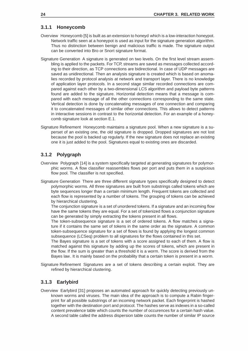
3.1.1 Honeycomb
Overview Honeycomb [5] is built as an extension to honeyd which is a low-interaction honeypot.Network traffic seen at a honeypot is used as input for the signature generation algorithm.Thus no distinction between benign and malicious traffic is made. The signature outputcan be converted into Bro or Snort signature format.
Signature Generation A signature is generated on two levels. On the first level stream assem-bling is applied to the packets. For TCP, streams are saved as messages collected accord-ing to their direction, as TCP connections are bidirectional. In case of UDP messages aresaved as unidirectional. Then an analysis signature is created which is based on anoma-lies recorded by protocol analysis at network and transport layer. There is no knowledgeof application layer protocols. In a second stage similar recorded connections are com-pared against each other by a two-dimensional LCS algorithm and payload byte patternsfound are added to the signature. Horizontal detection means that a message is com-pared with each message of all the other connections corresponding to the same state.Vertical detection is done by concatenating messages of one connection and comparingit to concatenated messages of similar other connections. This allows to detect patternsin interactive sessions in contrast to the horizontal detection. For an example of a honey-comb signature look at section E.1.
Signature Refinement Honeycomb maintains a signature pool. When a new signature is a su-perset of an existing one, the old signature is dropped. Dropped signatures are not lostbecause the pool is backed up regularly. If the new signature does not replace an existingone it is just added to the pool. Signatures equal to existing ones are discarded.
3.1.2 Polygraph
Overview Polygraph [14] is a system specifically targeted at generating signatures for polymor-phic worms. A flow classifier reassembles flows per port and puts them in a suspiciousflow pool. The classifier is not specified.
Signature Generation There are three different signature types specifically designed to detectpolymorphic worms. All three signatures are built from substrings called tokens which arebyte sequences longer than a certain minimum length. Frequent tokens are collected andeach flow is represented by a number of tokens. The grouping of tokens can be achievedby hierarchical clustering.The conjunction signature is a set of unordered tokens. If a signature and an incoming flowhave the same tokens they are equal. For a set of tokenized flows a conjunction signaturecan be generated by simply extracting the tokens present in all flows.The token-subsequence signature is a set of ordered tokens. A flow matches a signa-ture if it contains the same set of tokens in the same order as the signature. A commontoken-subsequence signature for a set of flows is found by applying the longest commonsubsequence (LCSeq) problem to all signatures for the flows contained in this set.The Bayes signature is a set of tokens with a score assigned to each of them. A flow ismatched against this signature by adding up the scores of tokens, which are present inthe flow. If the sum is greater than a threshold it is a worm. The score is derived from theBayes law . It is mainly based on the probability that a certain token is present in a worm.
Signature Refinement Signatures are a set of tokens describing a certain exploit. They arerefined by hierarchical clustering.
3.1.3 Earlybird
Overview Earlybird [31] proposes an automated approach for quickly detecting previously un-known worms and viruses. The main idea of the approach is to compute a Rabin finger-print for all possible substrings of an incoming network packet. Each fingerprint is hashedtogether with the destination port and protocol. The hashes serve as indexes in a so-calledcontent prevalence table which counts the number of occurences for a certain hash value.A second table called the address dispersion table counts the number of similar IP source

3.2 Flexible content-based signatures 25
and destination addresses for each hash value. Sorting the prevalence table with respectto the substring counters and taking into account the size of the corresponding entries inthe dispersion table one gets a set of likely worm traffic. This approach is called contentsifting.
Signature Generation The system generates pattern-matching signatures formatted for theSnort intrusion detection system including transport protocol and port information. As thecontent-sifting algorithm does not keep any per-flow state the generated signatures de-scribe only content information contained within a single packet. An example of an early-bird signature can be found in section E.2.
3.1.4 Autograph
Overview Autograph [9] is a system for automated generation of worm signatures. The sys-tem maintains a suspicious flow pool for which TCP flows are reassembled. If the numberof flows for a specific destination port exceeds a threshold the signature generation pro-cess is initiated. Autograph measures the frequency with which non-overlapping payloadsubstrings occur across all suspicous flow payloads and proposes the most frequentlyoccurring substrings as signature candidates. This is done by the content-based payloadpartitioning (COPP) algorithm.
Signature Generation The above signature candidates are filtered for possible benign content.In a repetitive process the most prevalent content block is selected as signature. Thisprocess repeats with the remaining flows, until some fraction of all flows in the pool hasbeen covered. Finally a set of selected signatures can be formatted as Bro signatures.
3.1.5 TaintCheck
Overview TaintCheck [13] uses dynamic taint analysis to protect designated applications.Whenever tainted data is used in a way that is disallowed by the installed policy,TaintCheck generates an alert and launches the signature generation process. The outputis a three byte long string signature.
Signature Generation The three bytes of the signature are determined by matching the mostsignificant bytes which were used to overwrite a return address or a function pointer withthe originial content, i.e. network data is compared against memory data. If the originalcontent and the three bytes do not match, some decoding or other data transformationoperations have been applied between data input and attack detection. In this case theoriginal content is used as a signature. The signature length of three bytes is too shortbecause assuming an uniform byte distribution would lead on average to one false positiveper 16 MB of traffic.
3.2 Flexible content-based signatures
These approaches on the one hand work on a byte level as the methods in the previous sec-tion. But on the other hand they are more flexible in that they do not just try to match stringsor substrings with incoming packets. Their signatures describe patterns of how malicious bytesare organized. Example techniques are the use of byte-frequency distributions or regular ex-pressions.
3.2.1 PADS
Overview The position-aware distribution signatures (PADS) system [36] uses a double-honeypot system to track malicious activities in local networks. A high-interaction honeypotredirects connections to low-interaction honeypots. When the high-interaction honeypotgets compromised, the low-interaction honeypots will be able to capture several wormvariants. Worm signatures are computed off-line.

26 CHAPTER 3. RELATED WORK
Signature Generation The PADS signature consists of a signature for normal and anomaloustraffic. Both signatures contain byte frequency distributions (instead of fixed values) foreach position in the signature string2. Signature generation and worm identification ina payload are very related. To understand the signature generation process the wormidentification process needs to be understood.To examine a byte sequence for the existence of a worm, a window of the length of aPADS signature slides over the byte sequence and computes a matching score ∆ forevery window W . This matching score is a formula that involves computing a matchingscore M for both the byte sequence with the anomalous and the normal signature. If thematching score ∆ for a window position is higher than a threshold (which is normally zero),the sequence is assumed to carry a worm.The position of the window with the highest matching score is called significant region.For finding a worm signature we need this region because the anomalous signature is thebyte-frequency distribution (BFD) of the significiant regions of all worm variants at handduring the signature generation process. If the significant regions of all worm variantswere known the BFD could be easily computed and so the signature. But to know thesignificant regions we would have to know the signatures which we don’t. Fortunately wecan approximate the significant regions for all the worms by applying the expectation-maximization (EM) algorithm.
3.2.2 PAYL
Overview PAYL [16] is an anomaly detection sensor that detects inbound anomalous loads,and correlates them with outgoing traffic on the same ports.
Signature Generation The PAYL anomaly detection sensor computes during a training phasethe ”normal profile” of a site using n-grams. For a packet payload, an n-gram consists ofany sequence of n consequent bytes in the payload. When a new packet arrives, all possi-ble n-grams are computed for it and also the frequencies of these n-grams are registered.Then a formula is used to compute the distance between arriving packets and the n-gramdistribution, which was seen during the training phase. If this distance is larger than athreshold and the incoming traffic was intended for port i, then such packets are put intoa buffer list of ”suspects” for port i. Any outbound traffic to port i, which is also detectedas anomalous using the anomaly detection sensor, is compared with this buffer. For thecompared strings, a similarity score is computed based on a formula, which requires thegeneration of the longest common substring (LCS) and the longest common subsequence(LCSeq) of the two strings. If the similarity score is greater than a threshold, the outgoingtraffic is blocked. As a by-product of the correlation between inbound and outbound traffic,a signature for the worm is generated in the form of a LCS and a LCSeq.
3.3 Context and semantics aware signatures
These approaches go beyond the previous approaches and the byte level analyzation respec-tively. They understand application-level protocols and thus can determine in which states anapplication has to be for unveiling an exploit.
3.3.1 Nemean
Overview Nemean [35] provides automatic generation of intrusion signatures from honeypotpacket traces. The system consists of the Data Abstraction Component and the SignatureGeneration Component. The Data Abstraction Component normalizes packets and per-forms flow aggregation by ordering the packets into connections (multiple packets betweentwo hosts) and sessions (multiple connections between two hosts). At last the aggregatedsessions are normalized via pre-defined service specifications, e.g. for HTTP. The outputof this component is a semi-structured session tree.
2The byte frequency distribution of normal traffic is equal for all bytes.

3.4 Other approaches 27
Signature Generation The Signature Generation Component groups sessions and connectionsaccording to a similarity metric. Automata learning is used to construct an attack signaturefrom a cluster of sessions or connections and these Finite-State-Automata signatures aretransformed into a signature format of an IDS.
Signature Refinement As clustering is used to group session and connection information tosignatures, refinement could be done by successively applying the clustering algorithm.
3.3.2 COVERS
Overview The COntext-based, VulnERability-oriented Signature (COVERS) [37] system allowsto automatically generate attack signatures for control flow hijacking attacks. It consists ofan attack detection part and a signature generation part. The attack detection part employsthe address space randomization (ASR) technique in contrast to e.g. Argos which usesdynamic taint analysis.
Signature Generation Signature generation consists of three steps. The correlation step iden-tifies the specific network packet (or flow) involved in an attack, and the bytes within thispacket that were responsible for triggering the alert. To identify the relevant bytes a foren-sic analysis of the victim process memory around the corrupted pointer is done by usingthe LCS method on recent input data and the data held in memory. However there aresome cases where this approach will not produce meaningful signatures.In a second step application protocol fields are analyzed whereas a language for sim-ple message format specifications has been developed. After the field is identified by thespecification, abnormal field characteristics are identified by comparing the field againstreference values which are continuously updated using benign input traffic.The signature consists of the message format specifier, the message field carrying theexploit and thresholds for the characteristics. An example can be found in the section E.3.
3.3.3 Polymorphic Worm Detection using structural Informa tion of Exe-cutables
Overview In [6] an approach is presented to generate signatures for detecting polymorphicworms. It is based on the control flow graph (CFG) of executable code. First a lineardisassembler extracts a sequence of valid instructions. Then a CFG is created for whicha spanning tree is calculated. From this all possible k-node subtrees with a selected basicblock as root node are generated. These trees also include non-spanning-tree links. Theadjacency matrix of each tree is combined with node colors (14-bit vectors) which providean indication of the instructions in a basic block. Out of the matrix a fingerprint is computed.The detection part is very similar to the Earlybird approach (see subsection 3.1.3). Themain difference is the mechanism used to index the prevalence table. While Earlybirduses simple substrings, this approach uses fingerprints extracted from CFGs. Thus wormsare identified by checking for frequently occurring executable regions that have the samestructure.
3.4 Other approaches
In this section approaches are presented which can not be classified as signature generationmechanisms (SGMs). Nevertheless these methods describe interesting ideas which could beused in a future SGM.
3.4.1 DOME
Overview The Detection Of Malicious Executables (DOME) [12] approach allows to detect codeinjection attacks and attacks originating from executables with modified code. The detec-tion mechanism is based on the fact that malicious code often makes use of system calls.DOME makes a static analysis of the executable of an application to identify the location

28 CHAPTER 3. RELATED WORK
of system calls in it and supervises if the locations at runtime differ. Although DOME doesnot generate any signature describing malicious activities, it can recognize such activitiesby verifying any activity against a signature describing normal/approved behavior.
3.4.2 Paid
Overview The Program semantics-Aware Intrusion Detection system (PAID) [17] defends ap-plications against control flow hijacking attacks that make use of system calls. It analysesthe location and ordering of system calls and parts of the control flow of the applicationwith the aid of the application’s source code.
Signature Generation The recompilation step analyses the system call usage of an application’ssource code and constructs a System Call Site Flow Graph (SCSFG), which is includedin the resulting library or executable. This graph is a deterministic finite-state automaton(DFA) representing the system call sequences and their location (site) in the program.
3.4.3 HoneyStat
Overview HoneyStat [7] is a system which combines network and host level attack detectionmethods. A HoneyStat node emulates multiple operating systems and detects three dif-ferent types of events: memory events, network events, and disk events. The system doesnot generate any signatures from the generated events but information during an event isrecorded. The gathered information is forwarded to a central analysis node which corre-lates all received HoneyStat events.
3.4.4 Vigilante
Overview Vigilante [20] is an end-to-end approach to contain fast spreading worms usingcollaborative worm detection at end hosts. The system introduces the concept of self-certifying alerts (SCAs). A SCA contains a description of an attack that is detailed enough,to allow other hosts to verify, if they are vulnerable to it. This is done by replaying the mes-sage(s) of a SCA in a sandboxed version of the targeted service. This SCA verificatorreplaces the section that is marked as critical with a nonce. If the nonce is activated andthus the host is vulnerable, it could generate a protection filter for the corresponding at-tack. SCAs have been developed for three common vulnerabilities. Arbitrary ExecutionControl (AEC) SCAs identify vulnerabilities that allow worms to redirect execution to arbi-trary pieces of code. Arbitrary Code Execution (ACE) SCAs describe code-injection vul-nerabilities. Arbitrary Function Argument (AFA) SCAs identify data-injection vulnerabilitiesthat allow worms to change the value of arguments to critical functions such as the execsystem call.
Signature Generation The three types of SCAs have a common format: an identification of thevulnerable service, an identification of the alert type, verification information to aid alertverification, and a sequence of messages with the network endpoints that they must besent to during verification. The verification information allows the verifier to craft an exploitwhose success it can verify unequivocally. It is different for the different types of alerts,e.g. for AEC an SCA specifies where to put the address of the nonce code to execute inthe sequence of messages. In the section E.4 an example of an AEC SCA is given.

Chapter 4
Application Protocol Plugin
4.1 Requirements
As NoAH is primarily meant to detect exploits for server software the application protocol to beimplemented in the tracker should be a client/server application protocol, e.g. the HTTP pro-tocol. Because in the second task state information of this application protocol plugin will beused for exploit signature generation, exploits for this protocol have to be available. So priorto the design and the implementation of the plugin a survey of available exploits in relation tothe corresponding network protocols had to be done. During the design of the plugin anotherimportant requirement emerged. Several network protocols use multiple connections in parallelfor the hosts communicating with each other, e.g. one connection for exchanging control com-mands and an arbitrary number of connections for exchanging data as it is the case for the FTPprotocol. In this case it could be possible that a network packet belonging to a data connectionarrives at the Tracker for processing before the data connection initiating control packet arrives.In this case of possibly asynchronously arriving network packets the Tracker has to be able tocollect packets although they do not actually belong to one of the implemented protocol plugins.The section about the non-protocol specific gargabe collector plugin devotes to this aspect.
4.2 Exploit survey and Protocol Evaluation
Software vulnerabilities do neither depend on the purpose for which the software was writtennor on which target platform or operating system it will run. Vulnerabilities rather depend on thedevelopment process and the technologies used throughout. Consequentially the number ofoccurring vulnerabilities in network software and thus possible exploits varies for software prod-ucts and not for protocols. Testing the signature generation mechanism implied to have severalsuccessfully executable exploits for the same protocol. It has shown that the number of avail-able exploits for the same application protocol differs but remains very low. Even if an executableexploit is available, it is not sure that the vulnerable version of the target server software canbe found. And even in this case, the success of an exploit depends on the vulnerability of theoverall target system. For instance the success of an exploit for server software on Linux mayvary for each distribution and version. This is the reason why Windows 2000 was selected asthe primary target operating system to attack. Furthermore Windows 2000 is more susceptibleto remote exploits than its widely used successor Windows XP.Because exploiting software is a very complex and cumbersome craft it has been decided to usethe Metasploit framework [28] for attacking the containment system. Logically even less exploitsare available for this attack framework. For the evaluation of the most suitable application net-work protocol which will be implemented in form of a plugin, different exploits in the Metasploitframework and the corresponding exploitable software had been searched and tested. The ta-bles 4.1 and 4.2 list the most important and usable exploits available for FTP and HTTP protocolrespectively. The tests have been done with target machines running Windows 2000 (Win2k),both english and german version, and Windows XP. A test was either successful (
√) or it failed
(X). The fields marked with an asterisk represent exploits which triggered the vulnerability, e.g.the buffer overflow, but could not execute the shell code successfully.
29

30 CHAPTER 4. APPLICATION PROTOCOL PLUGIN
Exploit name DescriptionOS
Win2kDE Win2kEN WinXP
warftpd_165_user Uses overflow in the USERcommand.
√*
√
warftpd_165_pass Uses overflow in the PASScommand.
* * *
3com_3cdaemon_ftp_overflow Overflow via the USER com-mand.
* *√
slimftpd_list_concat LIST command with overly-longargument triggers overflow.
X X *
cesarftp_mkd Improper input validation allowscode execution via overflow.
* X *
Table 4.1: Tested FTP exploits for the metasploit framework
Exploit name DescriptionOS
Win2kDE Win2kEN WinXP
trackercam_phparg_overflow Stack overflow via PHP argu-ments.
X * *
minishare_get_overflow Buffer overflow via missing Linklength validation.
* *√
apache_chunked_win32 Due to improper interpretationof an unsigned value, buffersizes for requests with chunkedencoding are computed wrong.
X X X
icecast_header Sequence of 32 http headerswill overrun a buffer.
√ √ √
ypops_smtp Too long smtp message over-flows a buffer.
* * *
Table 4.2: Tested HTTP exploits for the metasploit framework
Server applications for the file transfer protocol (FTP) exhibit a large number of similar bufferoverflow vulnerabilities. Mostly the buffer overflow can be triggered in an argument field of acommand request message. The kind of protocol-specific and typical buffer overflows for theFTP protocol, and the amount of available and successfully executable exploits for different FTPserver applications led to a more thorough examination of the protocol specification of FTP. Itis important to emphasize that from all examined protocols FTP is the one with the highestnumber of similar exploits for distinct server applications. Further there was a high percentageof vulnerable versions of server applications available with respect to the available exploits.
4.3 The File Transfer Protocol (FTP)
The FTP protocol sits on top of the transport layer in the OSI model and uses the transportcontrol protocol (TCP). It is commonly used for exchanging files over a TCP/IP network. Themain specification part can be found in the request for comment (RFC) document 959.FTP consists of two connections. The control connection normally is connected to the serverport 21 and initiates an arbitrarily number of data connections. The connection ports for thedata connections depend on the mode which was used to negotiate the data connection. Inactive mode the client creates a listening socket and tells the server via the PORT command onwhich port it is available. As incoming connections are often refused when the client is behinda firewall and/or a network address translation (NAT) box, the passive mode is mostly used inthe Internet. In the passive mode the client sends a PASV command to tell the server to open alistening socket on a certain port. This port is normally the port number of the control connectionon the server side minus one.FTP is based on the Telnet protocol. Commands are sent in cleartext and normally for eachcommand a reply is awaited. It consists of a three digit reply code and some human readable

4.4 The Garbage Collector Plugin 31
reply message. An example of a command specification taken from RFC 959 is given below. Allcommands are defined in Backus-Naur-Form (BNF) notation.Example Definition of the USER command in FTP:
USER <SP> <username> <CRLF><username> ::= <string>
A typical FTP command / reply sequence would be:> 220 Service ready for new user.> USER anonymous> 331 User name okay, need password.> PASS [email protected]> 230 User logged in, proceed.
The relation of data and control connections became of interest during the plugin implementa-tion, since the tracker has to temporarily store possible data connections for the case where thedata connection negotiation command would be processed delayed. This led to a second plugincalled the garbage collector.
4.4 The Garbage Collector Plugin
As shown in [21], all packets belonging to a certain network connection have to be processed bythe same thread, since state information for this connection is only available in the thread whichreceived the connection initiating packet. If for some reason the FTP command for negotiating adata connection would be buffered and the data connection initiating packet would be processedfirst, it may be possible that this packet will be delivered to the wrong thread. Actually it will notbe even delivered since we can not assign a port number for the data connections staticallybecause the port numbers are negotiated in most cases for the FTP protocol, as we have seenbefore. Then the tracker would discard the packets and our plugin never notices that the dataconnection was indeed opened. It may be even the case for more complicated protocols such aspeer-to-peer protocols that not even a single connection could be statically preconfigured sinceall ports are negotiated. These problems made a plugin necessary which buffers all packetsbelonging to a connection not assigned to a plugin. Note that the last scenario when we are noteven able to preconfigure a single connection with respect to the port assignments is not solvedby this plugin. However it would be easily possible to augment functionality of this plugin, e.g.by a polling mechanism, in order to come by this most complicated case.The most important structure in this plugin is the class SynchronizedMapwhich holds all pack-ets sorted according to the connections they belong to. In order not to overflow heap memory,packets are deleted in different situations. So what the garbage collector plugin actually does,is just to insert arriving packets into the synchronized map which is described in the followingsubsection.
4.4.1 Class SynchronizedMap
The class SynchronizedMap consists of a map called contentMap which holds con-nection information such as state changes sorted according to the connection keys foreach registered network packet. The number of maximum opened connections is limitedby MAX_OPEN_CONNECTIONS. Connections which get closed are registered in a sub-mapcalled closedMap which sorts connections according to the time when they were closed. IfCARE_CLOSED_INTERVAL number of elements have been inserted into closedMap, closedconnections are removed from all internal maps (contentMap and closedMap) if they havebeen closed for longer than CARE_CLOSED_TIME. The connection holding map has an upperbound number of contained elements of MAX_HASH_ENTRIES and each opened connectionmust not have more than MAX_ENTRIES_PERKEY. Note that according to this condition it fol-lows that
MAX_OPEN_CONNECTIONS * MAX_ENTRIES_PERKEY <= MAX_HASH_ENTRIES

32 CHAPTER 4. APPLICATION PROTOCOL PLUGIN
But what happens if we had the maximum number of opened connections and each openedconnection has the maximum number of entries? The map would be blocked and a new con-nection could not be added. A workaround is the following. We allow to set the constants ina way that the above inequality is hurt. But if we reach a number of connection entries biggerthan MAX_OPEN_CONNECTIONS * MAX_ENTRIES_PERKEY we switch to congested mode. Inthis mode we will force first the deletion of closed connections until we reach a limit number ofNUM_DEL_FORCED. If this is not possible it would be thinkable that we even remove entries foropened connections. As it becomes clear from the above explanations such a map is a compli-cated thing and needs a lot of fine tuning before it is used in a real-world scenario with a highamount of network traffic. Following the above mentioned maps for opened and closed connec-tions are shown as they are declared in the private section of the class SynchronizedMap.
• multimap<unknownConnectionKey, unknownConnectionInformation*>* contentMap;
The content map just maps information on a certain connection. Each arriving packet will putits information into this map in form of a map entry. This method allows us to have informationfor connections with the same end points but which chronologically differ in the same map. Thisis important because it is theoretically possible that two consecutive connections between twohosts could have the same port assignments but the tracker was not able to process informationabout the first connection when the second connection will be stored in the map. The map inthis case would mark the first connection as closed and then it will be possible to insert a newconnection with the same end points again.
• map<closedTimeval, unknownConnectionKey>* closedMap;
Each connection which will be closed gets an entry in this map. The keys are sorted accordingto the time when the connection was closed. This enables us to only delete the oldest connec-tions.
• sem_t*mapCompleteLock;
This is a semaphore which controls the access to the maps above. The maps can only beaccessed via certain API functions and those are made thread safe by use of this semaphore.
Class unknownConnectionKey
The class unknownConnectionKey describes an arbitrary connection to the server which ismonitored. This means that if we would track the connection states to more than one contain-ment system, we would have to add additional information to this class. However it was assumedthat monitoring one containment system is sufficient. A connection key has the following prop-erties:
Transport Layer Port This number corresponds to the port taken from the IP frame and e.g. stands forthe TCP protocol.
Client Network Address A network address can be currently either IP version 4 (IPv4) or version 6(IPv6). Further types of network layer addresses could be added.
Client Port The client port of the transport layer protocol, e.g. port 21 for the FTP protocol if TCP is thetransport layer protocol.
Server Port The port of the containment system.
As this class will be used in containers from the Standard Template Library (STL), the less-than-operator is overloaded. In the case of FTP it is possible that we only know one application port,either the one of the server or the client. This comes from the fact that either the client opens alistening socket (active mode) or it tells the server to open a listening socket for a certain port(passive mode). Either way only one port will be known beforehand. This is why a port set toSMAP_UNKNOWN_PORT will be ignored when two connection keys are compared against eachother.

4.5 The FTP Plugin 33
4.5 The FTP Plugin
4.5.1 Deriving a state machine for connection state observa tion
The FTP protocol defines five different state machines for request / reply sequences. Eachrequest command is assigned to one of these state machines. The most commonly appliedstate machines are shown in Figure 4.1 and 4.2. For each state machine the correspondingrequest commands are listed. Note that the reply codes shown besides the transitions denotethe first digit of the actual reply codes. This is because each of the three digits in a reply code issubject to some classification. Please refer to the original protocol specification (RFC 959, page34) for more details.
State machine one
Success
Error
Failure
Begin Await Reply
cmd
1,3
2
4,5
Figure 4.1: First state machine of the FTP protocol specification
Assigned request commands:ABOR, ALLO, DELE, CWD, CDUP, SMNT, HELP, MODE, NOOP, PASV, QUIT, SITE, PORT,SYST, STAT, RMD, MKD, PWD, STRU, and TYPE.
State machine two
Success
Error
Failure
Begin Await Reply
cmd
3
2
4,5
1
Figure 4.2: Second state machine of the FTP protocol specification
Assigned request commands:APPE, LIST, NLST, REIN, RETR, STOR, and STOU.
Additional state machines
For some special commands more specific and complex state machines exist which can beseen as concatenations of the above two types of state machines for two or three commands.In particular:
• The sequence of the RNFR command followed by the RNTO command describes its ownstate machine.
• The restart command REST has its own state machine and will be followed by eitherAPPE, STOR or RETR.

34 CHAPTER 4. APPLICATION PROTOCOL PLUGIN
• The login sequence with the commands USER, PASS and ACCT is the most complicatedstate machine and describes state transitions between those three commands whereasPASS and ACCT can be seen as optional.
A derived state machine
In order to be able to track the state of a connection we have to know exactly in which over-all state the connection is. This implies that we must have a single state machine which canbe used throughout the entire life cycle of the connection. There will be only one single entrypoint and one single state when the connection gets closed. The Figure 4.3 shows the derivedstate machine. Note that the properties of each of the five afore described state machines aresomehow contained in this new state machine. After each received reply message the state
Undefined
CommandAwait
USER
PreloginCommand Await
Prelogin NextCommand Await
Reply Await
Reply Await
Second ReplyAwait
Closed
PASS, ACCT
Reply Await
3,4
220
2
2
3
Command Reply
Reply
Reply
421
QUIT à 221
120
Figure 4.3: The derived state machine used by the FTP plugin
machine traverses one of the three in Figure 4.4 depicted states. These states however are just
Success
Error
Failure
Reply Next regular state
?
?
Figure 4.4: After each command / reply sequence one of the illustrated states is passed. Theydo not affect the FTP state machine itself but are meant rather for additional information.
for information and output purposes respectively and do not affect the internal current state.The three states correspond to the output states of the single FTP state machines. Using theabove temporary states makes sense because we actually have to track the state of the serverpart of the communication. This is the network site which is known and it should be not possiblethat the server application is comprised. So the definitive state transition will be just done whenthe server response has been received. After reply reception we will emit information about thestate of the server - either the request from the client caused an error, a failure or it was suc-cessful.The overall state machine has been implemented rather straightforward. There is a classFtpData which holds all the possible requests and replies. For this purpose the following two

4.5 The FTP Plugin 35
data structures requestCommand and replyCode are used. Listing 4.1 shows the declarationof those structures.
Listing 4.1: The structures representing requests and replies respectively
s t ruc t replyCode{
unsigned short code ; / / The rep l y codeunsigned short f i r s t D i g i t ; / / The f i r s t d i g i t o f the rep l y code , e . g . 5xxchar ∗ msg ; / / The message which should be p r i n ted i f t h i s rep l y
/ / code i s detectedunsigned short argumentType ; / / The type of argument to parse . Cu r ren t l y on ly
/ / hos tpo r t i s implemented f o r the r e p l i e s
replyCode ( unsigned short , unsigned short , char ∗ , unsigned short ) ;} ;
s t ruc t requestCommand{
char ∗ cmd ; / / The command as a s t r i n gchar ∗ msg ; / / The message which should be p r i n ted i f t h i s rep l y
/ / code i s detectedchar ∗ nextCommand; / / Some requests need f u r t h e r commandsunsigned short argumentType ; / / The type of argument to parse .unsigned short cmdSize ; / / The s ize o f the command, e . g . 3 d i g i t s
/ / ( impor tan t f o r pars ing the arguments )set < in t >∗ val idReplyCodes ; / / Each command has a set o f a l lowed r e p l i e s and
/ / these r e p l i e s r e s u l t i n a new s ta teunsigned short stateType ; / / One of the s ta te machines from the s p e c i f i c a t i o n
requestCommand ( char ∗ , char ∗ , char ∗ , unsigned short , unsigned short ,set < in t >∗ , unsigned short ) ;
~requestCommand ( ) ;} ;
These data structures are hold by two containers from the Standard Template Library (STL) andare publicly accessible as members of the class FtpData. They are declared as following:
• typedef map<string, requestCommand*> requestMapT;
The request commands are hold in a map of this type. The requests are mapped to a uniquestring identifier which is the same as the command string in the structure requestCommand.
• typedef map<int, replyCode*> replyMapT;
The replies are hold in a map of this type. They are mapped to their unique reply code.
4.5.2 The plugin design
To track the state of a connection the plugin maintains a list of control connection items de-clared by the structure ftpConnectionId. Each connection is mapped to its correspondingstate related structure ftpControlConnectionInfo. This structure holds information aboutthe current state and a map of data connections which have been initiated by the control con-nection. Note that in the case of the PASV command which tells the server to create a listeningsocket, we just know if the control connection was successfuly negotiated when the serversends a reply with the number 227. For this reason the connection info structure also holdstwo data connection structures for the currently negotiated data connection and the data con-nection settings prior to the ongoing negotiation. This allows us to restore the previously dataconnection properties if a server refuses a passive data connection request. Data connectionsare described by the structure ftpDataConnectionInfo.The functionality of the entry function which is called for each arriving packet contains the fol-lowing main steps:
1. Look in the map holding active control connections if a connection for the given packetalready exists. If it exists go to 3.
2. Create a new entry for the current control connection.

36 CHAPTER 4. APPLICATION PROTOCOL PLUGIN
3. Test if the packet is a TCP closing packet. These packets are forwarded from the TCPplugin in order to have full knowledge of the connection state. If it is a closing packet, theconnection state will be set to closed. Succeeding FTP operations on this connection willbe ignored.
4. Decide from which site the packet originated. The packet parsing and state handling willbe somewhat different for request and reply messages.
5. Parse the message.
6. Update state and do reporting.
At some positions in the code this rather conceptual functionality had to be broken and espe-cially the order of first parsing the message and then update the state was not always the mostefficient way. This is the result of the need for one single overall state machine which emergedfrom the five possible state machines of the specification.
4.6 Evaluation
After implementing the FTP protocol plugin for the tracker framework, evaluation had been post-boned since the signature generator was intended to be demonstrated at the NoAH meetingin Amsterdam, NL. Because of this, evaluation of the plugin was planned to be done afterthe implementation of a first signature generator. Meanwhile we have been strucked that theimplementation-oriented design of the tracker framework is not very convenient. The reasonsare the following:
• Implementing a state tracking plugin for each desired protocol is cumbersome and re-quires too much effort. Protocols are seldomly fully specified and require a lot of experi-ence and effort to be implemented correctly. Furthermore extensions of the original proto-col specification often complicate the protocols and it has been sighted that even popularapplications omit extended functionality of the original network protocol.
• Adding additional functionality that has always the same basic structure as hardcodedplugins is normally not a good design choice. Generic design and configurability are thecatchwords for this point and are the techniques which constitute a valuable frameworkdesign.
• As network protocols are widely implemented and in use some already existing implemen-tations should provide the functionality instead of implementing twenty years old networkprotocols by our own from scratch.
These observations amongst others are recapitulated in section 6.1. Despite the further direc-tion of this work heading towards another approach than using the tracker framework a shortevaluation of the performance of the implemented plugin will be presented.
4.6.1 Tracking states
After a couple of initial tests it showed that not a single packet was forwarded to the FTP plugin.During packet analysis the invalid TCP checksum for each network packet attracted attention. Itcame out that this effect is caused by a feature of newer network interface cards (NICs) calledTCP checksum offloading. When this option is enabled, the network adapters will calculate thechecksum by themselves, making the CPU and the operating system not have to do this work.When we are capturing and analyzing outgoing network packets we normally receive packetsbefore they get to the network adapter and thus we won’t see the correct checksum becauseit has not been calculated yet1. Offloading parts of network protocol processing from the hostCPU is a hot topic in the research area of operating systems and network acceleration. Asa consequence testing the TCP checksum in the TCP plugin had to be deactivated. Anotheroption would have been to deactive offloading at the local host.Listing 4.2 shows a single but complete packet element as it is logged in the XML log file of theTracker. The listing 4.3 shows an excerpt of the Tracker log output for the FTP subelements ofthe packet elements only. It reveals that we are able to track commands and their replies andeven are able to make note of negotiated data connections.
1Source: http://www.wireshark.org/docs/wsug_html_chunked/ChAdvChecksums.html

4.6 Evaluation 37
Listing 4.2: A single packet element<packet packe t Id=" 1124 " thread =" 0 " captureTime=" 1189000430.798982" >
<IP src= " 192.168.3.10 " dest= " 192.168.3.11 " payloadSize = " 59 "d i r e c t i o n= " f romC l i en t " / >
<TCP connect ion Id=" 1111 " src−po r t = " 56417 " dest−po r t =" 21 " payloadLen= " 27 "newState="TCP_ESTABLISHED " / >
<FTP v a l i d =" t rue " ><request type="PORT" argParsed= " t rue " argVa l id = " t rue " argLength=" 20 "
newState="FTP_CTRL_REPAWAIT" l as tRep l y= " 215 " / >< / FTP>
< / packet>
Listing 4.3: Tracker log excerpt<FTP v a l i d =" t rue ">
<request type= "PORT" argParsed=" t rue " argVa l id = " t rue " argLength=" 20 "newState= "FTP_CTRL_REPAWAIT" l as tRep l y=" 215 " / >
< / FTP>
<FTP v a l i d =" t rue ">< rep l y type= " 200 " argParsed= " f a l s e " argVa l id =" f a l s e " argLength=" 0 "
newState= "FTP_CTRL_SUCCESS" currentCmd="PORT" / >< / FTP>
<FTP v a l i d =" t rue "><request type= " LIST " argParsed=" t rue " argVa l id = " t rue " argLength=" 0 "
newState= "FTP_CTRL_REPAWAIT" l as tRep l y=" 200 " / >< / FTP>
<FTP v a l i d =" t rue ">< rep l y type= " 150 " argParsed= " f a l s e " argVa l id =" f a l s e " argLength=" 0 "
newState= "FTP_CTRL_SECREPAWAIT " currentCmd=" LIST " ><dataConn p o r t S i t e =" c l i e n t " portNum=" 52092 " / >
< / rep l y >< / FTP>
4.6.2 Measuring performance
For measuring the delay added to the overall processing time of the Tracker an FTP batch jobwas used. Listing 4.4 shows the script.
Listing 4.4: FTP batch scriptopen 192.168.3.11 user Sysadmin p e t e r l i
d i rcd / pubd i rcd / uploadd i rrename t e s t . t x t neu . t x td i rrename neu . t x t t e s t . t x td i r
cd / pubget empty_document . b inget empty_document . t x tget short_document . b inget short_document . t x tget long_document . b inget long_document . t x t
by
It opens a connection to a remote host and performs different file operations. The time neededto process a packet is measured by using the system call gettimeofday before and after thepacket processing inside the code of the Tracker. The measurements can be enabled by usinga precompiler directive to set the variable PERFORMANCE_MEASUREMENT. Figure 4.5 shows thedelays for the processed packets exchanged with the FTP server according to the batch script.

38 CHAPTER 4. APPLICATION PROTOCOL PLUGIN
It can be seen that the FTP plugin has only a small part of the overall delay. Furthermore thedelay approximately remains constant. The overall delay was also measured without the use ofthe garbage collector plugin and has not shown any significant differences. The average delayinduced by the FTP plugin for processing FTP network packets is about 26 microseconds. Thisdelay corresponds to a one-digit percentage compared to the overall delay for processing apacket with the Tracker.
Figure 4.5: The delays for processing the complete packet and processing the FTP protocol partwith the FTP plugin respectively

Chapter 5
Signature Generator
In the context of the NoAH project, the goal of this thesis was to present a simple signaturegeneration mechanism (SGM) in a first step as a proof of concept (PoC). This simple SGM hasbeen presented at the NoAH conference in Amsterdam, Netherlands, in June 2007. The goalwas to demonstrate the successful collaboration of the NoAH project components, i.e. Argos,the tracker framework, the Signature Generator and an IDS supporting the signature format ofthe generated signatures.
5.1 Requirements
The signature generation component mainly can be divided into two parts. The first one isresponsible for correlating information from Argos and the Tracker and preparing the extractedinformation for the second component, the SGM. The SGM has the function to synthesize aconcrete signature for e.g. an existing IDS from the extracted information. It exists only oneextraction component but an arbitrary number of SGM components.Prerequisites for the information providing component are the following.
1. The information extractor has to work reliably. This means that during each process ofextracting attack information it is known how much information is available if any, and ofwhich quality the information is. The latter depends on the methods with those informationwas extracted as these have not always to be the same.
2. The information extraction should be fail-proof, i.e. it is not possible that an informationextraction process can terminate unexpectedly.
3. The information extraction should be fast. At this point the motto ”safety before speed”applies.
Prerequisites for the SGM components and for a simple SGM for demonstration purposes inparticular are
1. The target signature format should be compliant with at least one IDS available for free.
2. This IDS should be popular, widespread and easily configurable.
3. The signature rule language should be rather simple in order to create signatures effi-ciently. This assures that focus is laid on the information extraction.
4. In contrast to the above point the signature format should be powerful enough. This meansthat the accuracy of the extracted information should not be significantly reduced whentransformed into a signature of this format.
5. The signature format should allow signatures with a low false-positives rate. More explicitlythe false-positives rate should be constrained by the quality of the extracted informationand not by the signature generated thereof.
39

40 CHAPTER 5. SIGNATURE GENERATOR
5.2 Signature format evaluation
For a simple SGM the rule language to build signatures should be rather simple. Two of themost prominent open source IDS, Snort [11][1] and Bro [33][34], have been considered andwere compared against each other. Bro is to prefer over Snort if we want to build a customizedand very secure system. But because of the simplicity of the Snort rules and its architectureSnort has been chosen to serve as the basis for a first SGM. Furthermore the Bro system iscompatible with Snort rules. It has shown that the Snort rule language is quite powerful despiteits simplicity. In accordance to the stated prerequisite the Snort rules should not narrow thepower of the extracted information and thus should not increase the theoretical false-positivesrate of the extracted information.
5.3 Architecture
This section presents the architecture for the information extracting component. The extractedinformation could be seen as a generic kind of signature although this is not consequentlyrealized in the design1.
5.3.1 Extracting alert information
Recall from the Figure 2.2 that the interface connects the log file information available fromArgos and from the Tracker. From this information we should be able to extract useful attackinformation and generate a first simple signature.Because the code of the interface that was already available was not that big, we decided tointegrate the SGM into the interface. There are only a few classes involved in the signaturegeneration. The class Extractor extracts information from the given Argos log file and triesto correlate this information with the Tracker log files. The Argos alert reports are namedaccording to the following pattern:
argos.csi.<random alert identifier>
where the number random alert identifier (rid) is created by Argos and should beunique among the entire set of created alert reports. The available set of extracted informationfor describing an attack in the extractor class depends strongly on the state of the implemen-tation and research. Therefore the class can be seen as a container holding all the extractedinformation as members. For each information there will be a corresponding function which re-turns the information value.Each time an alert is generated by Argos the interface notices this by receiving a message atthe control socket connected to Argos. Subsequently the information extraction and signaturegeneration will be started.Snitch.pl is an additional process running on the guest system under attack and is usedto determine the process which has been attacked and some further information. The snitchprocess sends its information to the interface via a separate control socket. This is why a sec-ond thread was needed which waits for incoming messages from the snitch process. Becauseinformation from the thread connected to snitch is needed by the main process for signaturegeneration, a special map was needed which can be accessed safely by multiple processes.The class called SnitchMap uses a semaphore to protect its information from concurrent ac-cesses. This method is very similar to the one used by the class SynchronizedMap in thetracker framework. The interface polls the SnitchMap when it needs information for a certainalert report. Listing 5.1 shows how the interface gathers available information when an alertmessage from Argos was received.
Listing 5.1: Extracting the entire set of available information for signature generation/ / i n t r i d holds the cu r ren t random a l e r t i d e n t i f i e r
/ / Ex t rac t i n fo rma t i oni f ( e x t r a c t o r . e x t r a c t I n f o r m a t i o n ( " ArgosAler tRepor t " ) ){
/ / Access the synchronized map
1As we will see a refactored version of the information extractor will treat the extracted information as a genericsignature.

5.3 Architecture 41
Sni tchEnt ry ∗ cu r ren tEn t r y ;i n t count = 0 ;while ( ! snitchMap . unbagElement ( r i d , &cu r ren tEn t r y ) ){
s leep ( 5 ) ; / / s leep f o r 5 seconds and t r y againcount ++;i f ( count > 5) / / we won ’ t wa i t any t ime longer
break ;}i f ( count > 5)
/ / I n fo rma t i on f o r the cu r ren t r i d was not a v a i l a b l eelse
/ / We gathered i n fo rma t i on success fu l l y}
First information is extracted by the extractor class. If the extractor was successful, we look upat the snitch map for the appropriate snitch entry. We poll the snitch map repeatedly at a cer-tain polling interval until we either find the desired entry or we exceed the maximum numberof lookups. Because information from Argos is almost concurrently sent with the message fromthe snitch process, polling is reasonable. Information from the SnitchEntry object and infor-mation provided by the Extractor now can be combined for generating a signature.The class SignatureFactory is responsible for factoring a rule out of the extracted informa-tion. A class representing a concrete signature has to be derived from the class Signature. Afunction factoring a signature of this type has then to be added to SignatureFactory. Figure5.1 depicts the process structure of the NoAH core after introducing the snitch thread.
Honeypot
Application StateTracker
Interface
Main process
Snitch Thread
Argos.netlog
Argos.csi.x
NetworkNetwork
Socket
IPC
File I/O
NetworkNetwork
TrackerOutput.dat
TrackerDump.dat
SnitchPerl Script
ArgosControl Socket
Figure 5.1: The process structure after adding alert information extraction
5.3.2 Archiving signature information
The signature generator should be able to archive common information of an alert as wellas concrete signatures. This has been achieved by adding a simple MySQL database. In thisdatabase there are currently three important tables. One is for indexing the signatures, anotherholds all the common information. Concrete signatures should have their own tables. The threeavailable tables are described below.
signatures This table holds the meta information for a signature database entry. Tuples of thistable identify a signature in the database uniquely. The only master key in this scheme isprovided here.
details It provides detailed information on the attack like source port or the position where apossible buffer overflow occurred. This table is used to create specific signatures, e.g. aSnort signature. If a signature will be refined information has to be changed first here.
snortSignatures Shows the concept of how a concrete type of signatures could be stored in atable. Each signature class that is available should have its own table to store the rules.

42 CHAPTER 5. SIGNATURE GENERATOR
As the database itself could be on a remote machine or kept locally at the same place wherethe interface is running, different scenarios how to access the database and to provide APIfunctions are thinkable:
Local signature collection This scenario is denoted local because the signature collection, re-finement and deployment is done locally, in the same process. This approach was thoughtof as a first and simple approach, especially for demonstrating the abilities. Note that de-spite of the property ”local” the signature database itself could be on another site thanlocal.
Remote signature collection It is meant that we implement another signature collector classwhich would connect with a remote process for signature collection, refinement and de-ployment. In this case the signature database would be at the remote site too.
For demonstration purposes a local signature collector class LocalSignatureCollectorhas been written. The following functions provide the API for database access:
• bool insertSignature(SnitchEntry*, Signature*, Extractor&)
Inserts a signature into the database. If a signature for the corresponding attack already existsfirst a refinement is attempted. If a refinement is not possible a new signature for the same at-tack is created. If the refinement would not make sense the signature insertion is cancelled.
• bool updateSignature(Signature*, unsigned int)
This function can be used to update a signature of a concrete type.
As the collector classes represent the access point to the signature database they shouldprovide additional functions, e.g. for printing tables and converting numerical constants intotheir string representations. This is provided in LocalSignatureCollector by the functionsprint...() and resolve...(). Getting back to the process structure of the entire architec-ture we have added a database component as depicted in Figure 5.2.
Honeypot
Application StateTracker
MySQL Database
Interface
Main process
Snitch Thread
Argos.netlog
Argos.csi.x
NetworkNetwork
Socket
IPC
File I/O
NetworkNetwork
TrackerOutput.dat
TrackerDump.dat
SnitchPerl Script
ArgosControl Socket
Figure 5.2: The process structure containing a MySQL database
5.3.3 Demonstrating signature capabilities
For demonstrating the usability of the generated signatures a small Java server program hasbeen written that waits for a signature description. It then updates the Snort rules configurationfile and restarts the IDS. This can be easily done in Java by using the classes Runtime andProcess. The functionality to connect the signature generator with this demonstration host hasbeen integrated into the local signature collector as this is the place where signatures are storedand refined.

5.3 Architecture 43
5.3.4 Attack replaying
During the implementation it has shown that it could be useful to have a facility for replayingdetected attacks. A possible benefit is to refine the maximum length of a protocol field triggeringa buffer overflow. Furthermore it would be even possible to test the created signatures againstthe detected attack by using the attack replaying in conjunction with the demonstration host.This approach describes a similar methodology as proposed by Microsoft research introducingself-certifying alerts (SCAs). This approach has been presented in the related work chapter insection 3.4.4.Attack replaying comprises the following steps:
1. The available replay target systems for a certain attack are identified. Currently this is doneby reading the available services and the platform properties from a XML configuration file.
2. Then it is tested if the target is responding but no service of the requested type is running.
3. The remaining targets can now be used for replaying. The server application to be attackedis started by using a secure shell (SSH) connection.
4. If the service does not respond after the attack we can assume that the attack was suc-cessful. When we close the SSH connection the child processes and thus the startedservice will be terminated properly.
Each replay target system is represented by an instance of the class ReplayTarget. Theclass AttackReplayManager starts the attack replaying mechanism, either as a set of syn-chronized processes or in the same process. This allows us to even use multiple machinesto attack replay targets. This resulting ”one-to-many-to-many” relationship between the signa-ture generation mechanism and the replay targets avoids the vulnerability to Denial-of-Service(DoS) attacks by minimizing the possible bottle necks. The relationship is illustrated in Figure5.3. The replaying process itself is done by objects of the type AttackReplayer. This class
MySQL Database
Attack Replayer
Attack Replayer
Service ControlSocket
IPC
File I/O
Attack Replay Manager
Replay Target
SSH Daemon
Service module
Attack Replayer
Attack Replayer
Service Control
Attack Replayer
Attack Replayer
Service Control
Replay Target
SSH Daemon
Service module
Replay Target
SSH Daemon
Service module
Figure 5.3: The ”one-to-many-to-many relationship” for the attack replaying mechanism
manages the connection for the attack replaying and starts a concurrent control process for theSSH connection. If we want to have the ability to replay an attack for a certain application proto-col, we have to derive a class for this protocol from AttackReplayer. For demonstrating theconcept an FTP attack replayer has been implemented. Figure 5.4 shows the overall and finalarchitecture with all its interacting components. It has to be admitted at this position that ”self-certifying” the generated signatures was achieved only in a restricted sense. The achievement

44 CHAPTER 5. SIGNATURE GENERATOR
Demo Host
Snort .rules file
Replay Target
SSH Daemon
Service module
Honeypot
Application StateTracker
MySQL Database
Interface
Main process
Snitch Thread Attack Replayer
Service Control
Argos.netlog
Argos.csi.x
NetworkNetwork
Socket
IPC
File I/O
NetworkNetwork
TrackerOutput.dat
TrackerDump.dat
signatureServer
SnitchPerl Script
ArgosControl Socket
Figure 5.4: The complete process structure of the signature generation mechanism
was the functionality to replay FTP conversations up to the packet triggering the buffer overflow.The buffer overflow has been verified by generating packet fields that are longer than the bufferlength of the vulnerable application. This information can be obtained from the generated sig-natures.The actual information provided by the signature is not the bound of the buffer length whichleads to a buffer overflow, but the critical buffer length which overwrites a target address forexecution. Protecting the application from overwritten jump targets or return addresses insteadfrom the buffer overflow itself is not a big difference since control-flow hijacking can be preventedeither way. Argos aims mainly at the detection of remote code execution attacks. Control-flowhijacking is the method enabling exactly such attacks.So at least it is possible to verify that a signature describes a vulnerability and that this vulnera-bility can be triggered by the packet field and field length specified.
5.4 A signature generation mechanism (SGM)
A simple approach to generate signatures from the Argos log files was proposed in [3]. Theauthors have applied the LCS method to extract a content string which will serve as an identifierfor the detected attack. This string could be easily used in e.g. a Snort signature. More preciselyArgos can detect if an overwritten return address is about to be used in the control flow. Thisoverwritten return address is identified in the corresponding network packet. The position foundin the network packet is then used to apply an LCS search around the return address in boththe process memory and the network packet. The LCS approach was reimplemented with ade-quate effort by using the Cargos library. This library provides an API for accessing the log filesgenerated by Argos. A Snort signature generated by this SGM could look as following:alert tcp any any -> any 21 (content:"|05 D3 FF 00 09 A4 C6 12|";)
Because the extracted byte string can contain information that could be altered but the vulner-ability could still be triggered and the exploit executed, a signature created by this method willnot be able to identify altered attacks of the same exploit. Even if only the value of the returnaddress itself is taken as the byte string, the address may be slightly changed and the rule willnot trigger anymore. On the other hand the less bytes are contained in this signature the higherthe possible false-positives rate will be.This is where the log files from the Tracker come into play. In the state tracking XML log filewe have a string contained which identifies the message type, e.g. a command string for FTPcommand messages. With this information it is possible to have less information in the contentstring. A possible Snort signature could now look as following:

5.5 Evaluation 45
alert tcp any any -> any 21 (content:"USER"; content:"|09 A4 C612|";)
However the problem remains the same. As we have a small byte string the false-positives ratewould be high. So what do we actually intend to achieve our generated signatures? We try toprevent an application-specific exploit from taking place. In other words we try to protect thevulnerable service from exploits triggering its vulnerability. As the cause for a buffer overflowoften is a protocol field of variable length a possible countermeasure is to filter network packetswith a certain protocol field being longer than the biggest legitimate buffer size. In the case ofthe FTP protocol this is simple since the field of variable length in command messages is thelast field of the message. Thus the Snort signature looks as following:alert tcp any any -> any 21 (content:"USER"; dsize:>32;)
This rule assures that the user name extracted from the message will be not longer than acertain maximum length. A buffer overflow caused by too long user names can not be triggeredanymore. As already mentioned in the previous section the maximum length for a protocol fieldas specified by our signatures is not the bound at which the buffer overflow would be triggeredbut at which the control flow of the application would be altered instead, e.g. by overwriting afunction’s return address. This is because Argos determines when and at which position tainteddata will be executed. But this information may not be sufficient to estimate the real boundfor triggering the buffer overflow. However protecting a vulnerable application from altering itscontrol flow is regarded as a very strong protection unless as even powerful as protecting fromthe buffer overflow itself.Unfortunately for variable-length fields that do not occur at the end of a packet the methodpresented above obviously does not work. To come by this shortcoming a more elaboratedarchitecture for the signature generation is presented in chapter 7.The above presented SGMs have been imlemented but only the first approach is not dependenton the application protocol. For the other two approaches an application protocol plugin for thetracker framework is necessary. The implementation of an application protocol plugin for theFTP protocol has been presented in chapter 4. Note that the signatures shown are simplified. Acomplete signature generated would look like the following:alert tcp any any -> any 21 (msg: "(NoAH) Overwritten return addressvia FTP USER command in warftpd.exe (win2k)" dsize:>15; flow:established,from_client; content: "USER"; nocase; content: "|E2 3102 75|"; sid:1000005; rev:4;)
5.5 Evaluation
As explained in the section 4.2 an attack usually exploits one or more security-related vul-nerabilities caused by software bugs which normally have their roots in the implementationor design. This is why exploits are only exemplarily available. It follows that measuring thefalse-positives rate for the generated signatures does not have to be compellingly reliable.One often made mistake regarding the generation of attack signatures is that the signaturesdo not take into account the vulnerable application itself that initially enabled the exploit.But this is one of the most valuable information since applications merely exhibit exactly thesame vulnerability. Information about the targeted application is not supported by the Snortrules language which poses a major drawback. However, it is thinkable to select the activeset of Snort signatures for the Snort IDS according to the running services by an externalprogram. This way we could guarantee that each active signature on the host protects arunning application with an existing vulnerability. The signature database stores the name ofthe vulnerable application and the platform for each signature.A signature is the better the more it describes the vulnerability of the application and not justproperties of the attack exploiting the vulnerability. With the presented approach of using Snortrules to protect variable-length fields the signatures protect the vulnerability pretty accurately.
The extracted attack information allows the creation of signatures with a zero false-positives ratewhen

46 CHAPTER 5. SIGNATURE GENERATOR
1. Argos detects the execution of tainted data, e.g. data injected via the network that isabout to be executed. This corresponds to a remote code execution attack. In this casethe interface will receive the address value of the target instruction. Normally the targetaddress of e.g. a return or jump instruction has been overwritten via a buffer overflow.
2. We are able to read the instruction value from the memory dump of Argos at the addressgiven from above.
3. It is possible to identify the network packet from which the target instruction originated.
4. The buffer overflow used to overwrite the instruction’s target address was triggered by atoo long protocol field of variable length.
5. The Tracker log file provides information for a protocol message type identifier.
If some of the above conditions do not hold we could generate some kind of emergency signa-ture. An example for this sidestep strategy are byte matching algorithms between the memoryand the network data creating some kind of byte string identifier. The LCS algorithm is oneexample of such an algorithm. The different possible signatures have been described in thepreceding section. With a byte string identifying the exploit the false-positives rate would bepoor. This is because benign network traffic could contain the string too. We can weaken theeffect of such signatures by assigning poor quality to the signature, by refining it or even bydiscarding the signature.Note that the architecture and the SGM presented in this chapter have further restrictions. Theyhave been overcome with the refactored version of the signature generator presented in chapter7. The two most important restrictions are
1. The vulnerable field of variable length has to be the last field in the network packet.
2. The Tracker must have plugins for the appropriate protocols and the log file must provideinformation on the appropriate network packet.
Performance aspects are not considered in this chapter but are presented for the refactoredsignature generator in chapter 7. However, the presented delays for the refactored signaturegenerator are in the same range as the ones for the original signature generator.

Chapter 6
A more generic approach forsignature generation and statetracking
6.1 Observations
Protocol knowledge and decoding
As we have already seen at the end of the previous chapter the so far implemented signaturegeneration mechanism has the disadvantage that the signatures are either not very precise orthe mechanisms require implemented plugins which fully support the protocol decoding, de-noted by protocol knowledge. This protocol knowledge is used by the SGM as well as by theTracker and the attack replaying mechanism. Implementing plugins for each desired protocolis cumbersome and error-prone. Furthermore adding additional functioniality, here the protocolplugins, in form of hardcoded functions is not state-of-the-art. Searching protocol fields for theirbounds which are not at the end of the messages unlike in the previously presented case ofthe FTP protocol will increase complexity of the parsing algorithms further. Recapitulatory it canbe stated that our components such as the Tracker or the SGM has the need for full protocolknowledge. This can only be achieved with an adequate effort if the components can revert toan existing library providing at least functionality for protocol field parsing.
A generic state machine
For the Tracker and the attack replaying mechanism we need not only protocol knowledge but astate machine for each desired protocol. Note that for these two components the state machineswill differ in some points. So as we can see we have the demand for a generic protocol statemachine in addition to the protocol decoding. The state machines should be configurable foreach protocol according to some specifications. The section 6.5 presents different approacheshow a state machine can be implemented and how configurability can be obtained.
Knowledge of protocol field meaning
In the case of the replaying mechanism even knowledge about the meaning of protocol fields isneeded. This implies that protocol decoding itself is not sufficient. For field decoding we have toknow for instance the length of the field and its data type. But for replaying a network conversa-tion we additionally have to know what the fields mean or in other words what purpose a field isfor. In the section 6.6 some ideas for achieving synthesis of network packets on application-levelare discussed briefly.
47

48CHAPTER 6. A MORE GENERIC APPROACH FOR SIGNATURE GENERATION AND
STATE TRACKING
Conclusions
Overall, the consequences of the observations presented in this section are the necessity ofa redesign of the entire tracker framework, parts of the signature generator and the attackreplaying mechanism. The mentioned three techniques needed to accomplish the nontrivialtask of signature generation for almost arbitrary protocols will be addressed in the next sections,especially with respect to the implementation aspect.
6.2 Survey
In the previous section we concluded that we need
1. the ability to decode protocol fields denoted by protocol knowledge,
2. a generic and configurable protocol state machine,
3. knowledge of the meaning of protocol fields and how to synthesize them.
To accomplish the above three requirements in a first step available tools for complete protocolmodeling have been evaluated. Although a lot of research work exists on this topic librariesare seldomly publicly available. There is some interesting research work on the field of proto-col analysis but no work seems to fit our needs entirely. On the other hand some presentedapproaches appeared to be an overkill with respect to our needs. It has to be emphasized thatoften, especially in the case of research work, even if software is available for an approach theconfiguration and specification files for concrete network protocols were only written exemplarily.The following approaches are introduced briefly.
Specification and Description Language (SDL) SDL [32] is used for the description of re-active and distributed systems. It is a standard defined by the ITU-T. Opposed to theapproach of the IETF to specify standards in arbitrary text form the ITU-T intends to usea declarative language to exactly specify and determine behaviour of new protocols. Es-pecially in the field of wireless communication some example protocol specifications areavailable. However none of the IETF protocols seem to be available in SDL. A SDL com-piler is avilable from Humboldt university.
Generic application-level protocol analyzer (GAPA) This approach is presented in [24] byMicrosoft Research. It defines a protocol modeling language named GAPAL and uses astream-based technique to process network packets.
It turned out quickly that no suitable software library would be available which fits all of ourneeds. So we decided to look for approaches addressing only one of the above requirementsat a time. The section 6.3 addresses the first of the three above mentioned requirements. Thesection 6.5 is about a framework for a generic and configurable state machine. The conclud-ing section for this chapter, section 6.6 deals with the automated packet synthesis for packetreplaying.
6.3 Protocol knowledge
A survey of available approaches for protocol decoding is presented in this section. The oftenused abbreviation PDL stands for protocol declaration language and denotes a language whichcan be used to specify certain characteristics of a protocol such as field masks of specificpackets.
From the presented approaches in table 6.1 NetPDL had been investigated further. This dec-laration language is part of an extensive library called NetBee which is currently written at theuniversity of Turin, Italy. The presented framework supporting NetPDL was very promising andwill suffice our needs. The next section gives an overview of the NetBee framework.

6.4 The NetBee framework 49
Name Characteristics
libPDLa • Works on byte streams• No network protocols yet (used originally for MIDI protocols)
NetPDLb
• Potential for a new standard• Comes with PDML and PSML• Not yet completely ported to Linux• Performance comparable to Tethereal• Over 64 protocols available
Ethereal / Wiresharkc
• Protocol dissection and decoding engine Epan:◦ Supports over 700 protocols◦ Protocols are hard-coded in ANSI C, more than 800 kLOC• Seems not be intended for usage as external library
Tethereal / Tsharkc
• Uses Epan of Ethereal• Supports different outputs such as PDML, PSML or human-readable• Output seems to be only accessible from a file
tcpDumpd• Usage not clear, seems not to be intended for library usage• Not many protocols• Protocols are hard-coded
GASPe
• GASP = Generator and Analyzer System for Protocols• Compiler generates protocol-specific code• Framework is build on the script language Tcl/Tk• Most recent software release allows to encode and decode packetsof different protocols• Development seems to have been stopped
JNetStream Protocol Decoderf• Java library for easy manipulation of captured network packets• Based on IO streams• NPL (Network Protocol Language) is interpreted language for pro-tocol decoding• Listed for completeness
Black-box tools• Either commercial → no source code available• Freeware → No API available, no documentation, only a GUI in-stead
ahttp://nmedit.sourceforge.net/subprojects/libpdl.htmlbhttp://www.nbee.org/chttp://www.wireshark.org/dhttp://www.tcpdump.org/ehttp://laurent.riesterer.free.fr/gaspfhttp://sourceforge.net/projects/jnetstream/
Table 6.1: Overview of projects and standards for protcol analysis and decoding
6.4 The NetBee framework
The framework and the corresponding library NetBee are presented in [22]. The purpose of thislibrary is to provide a modular and flexible API for protocol analysis, traffic classification andpacket sniffing and filtering. The library consists of different modules which implement differentstandards, some of them developed explicitly for this framework. Amongst others the NetPDLlanguage is supported by NetBee. The library consists mainly of the following components:
• A Packet Decoder
• PSML and PDML Readers for decoded protocols
• A NetPDL Protocol Database
• An Interface for the NetVM
• A Packet Processor
To achieve protocol knowledge the packet decoder, its related PDML reader and the NetPDLprotocol database are particularly of interest. The packet decoder processes packets based onprotocol descriptions in the NetPDL language. NetPDL specifications are currently available for

50CHAPTER 6. A MORE GENERIC APPROACH FOR SIGNATURE GENERATION AND
STATE TRACKING
about 64 or more protocols and are stored in the protocol database. The two types of readersprovide categorized information of decoded packets. The PDML language will be presented ina following subsection and is very useful for packet decoding. Of minor importance is the PSMLspecification which describes just a summary of packet information and uses Visualization Ex-tensions of the NetPDL language.In the following first subsection the NetVM is described briefly. The packet processor componentlisted above uses the NetVM.
6.4.1 Network Virtual Machine (NetVM)
Network Virtual Machine (NetVM) is a virtual machine targeted to network packet processing.It is presented in [19]. The NetVM architecture is modelled after the one of an ideal networkprocessor, i.e. a processor that includes a set of hardware modules devoted to speed-up packetprocessing, e.g. lookup tables, and a set of assembly instructions that are targeted to commonpacket processing tasks, e.g. checksum computation. The NetVM defines
1. the architecture for a new network processor
2. how to interact with these components from an application
The NetVM aims at becoming a reference specification for network-related data processing.This interesting hardware-independent approach for network packet processing is of rather poorimportance for this work and it will not be referred to in the remaining text.
6.4.2 Network Protocols Description Language (NetPDL)
The NetPDL1 language is an XML-based language that aims at creating a unique databaseof protocols that can be used by arbitrary applications. It is presented in [23]. The languageintends to describe the basic features of each protocol, e.g. the protocol fields and the protocolencapsulation. Additionally, a set of optional specifications can be defined for some specifictasks. The NetPDL Visualization Extension aims at defining how to print a decoded protocol,e.g a 32 bit number representing an IP address should be visualized in the dotted-decimal form,and more. Each NetPDL engine must be able to parse the NetPDL specification, while it can beable to understand only the optional parts that are of interest of that application.The NetPDL language is easily extendible according to the needs of some particular application,its syntax is easy to understand, and the parsing is very simple thanks to the existing XMLtechnologies. A first implementation of a NetPDL engine (and a NetPDL database) can be foundas already mentioned in the NetBee library. Listing 6.1 shows an example definition in NetPDLfor the IP protocol.
Listing 6.1: Example of a NetPDL definition for the IP protocol< p ro toco l name=" IP " longname=" IPv4 ( I n t e r n e t Pro toco l vers ion 4) " >
<format >< f i e l d s >
< f i e l d type= " f i x e d " name=" verh len " longname=" Version and header Length " >< f i e l d type= " b i t " name=" ver " longname=" Version " mask= "F0" / >< f i e l d type= " b i t " name=" hlen " longname=" Header leng th " mask=" 0F" / >
< / f i e l d >. . .
6.4.3 Packet Details Markup Language (PDML)
The PDML language2 is a simple language that keeps the information related to a decodedpacket. PDML stands for packet details markup language and it is strongly related to NetPDL.This language is used by a NetPDL engine that understands the NetPDL Visualization Exten-sion to create a detailed view of each packet.A detailed view of a packet is an XML file that contains all the important information related toprotocols and fields that are contained in one packet, e.g. the protocols, all the field names andtheir values, and more. The PDML specification is a way to organize this information. However
1http://www.nbee.org/Docs/NetPDL/2http://www.nbee.org/Docs/NetPDL/PDML.htm

6.5 Protocol state automaton 51
the XML representation has not to be saved as a file stringently and could just be kept in mem-ory for further processing. A PDML document lists all the packets contained in a capture file,detailing the most important information for every protocol that has been found in the packetand for each field that has been decoded within the protocol.The PDML language is becoming a de facto standard in packet analysis and is already sup-ported by Wireshark and Tshark as an output method. Listing 6.2 depicts an excerpt of a PDMLdescription of a decoded packet for the IP protocol. It corresponds to the NetPDL definitionshown in listing 6.1.
Listing 6.2: Example of a PDML description for the IP protocol<pro to name=" IP " pos= " 15 "
longname=" IPv4 ( I n t e r n e t Pro toco l vers ion 4) " s ize= " 20 " >< f i e l d name=" verh len " pos=" 15 " showvalue= " 45 "
longname=" Version and header Length " s ize= " 1 " value=" 45 ">< f i e l d mask= "F0" name=" ver " pos=" 15 " showvalue= " 4 "
longname=" Version " s ize = " 0 " value=" 45 " / >< f i e l d mask= " 0F" name=" hlen " pos= " 15 " showvalue= " 5 "
longname=" Header leng th " s ize= " 0 " value=" 45 " / >< / f i e l d >. . .
6.4.4 Usage of the NetBee library
The NetBee library and its API seemed to be exactly what we have been looking for. In orderto be able to use the NetBee library and its source code for a few experiments we signed anon-disclosure agreement. Furthermore parts of the library had to be changed in order to rununder Linux since it was primarily developed for Windows. Fortunately the developers wrote thecode with portability in mind and most changes could be done with minor effort.At some points the API of the NetBee library is not very comfortable. Two façade classes havebeen written to access the library more easily. They are described briefly at this place and areexamined more thoroughly in the following chapter 7.
PacketDecoder This class can be used as an access point to the packet decoder mentionedin 6.4. It decodes a given packet and if the decoding was successful different field andprotocol information can be obtained from the object.
DbFieldDecoder Because the packet decoder of NetBee is not able to return any informationcontained in the NetPDL definition of a protocol we have to access the database interfacedirectly. The NetBee database API provides only basic functionality to access the NetPDLdatabase and it had to be extended by this class, e.g. looking up a given field for a certainprotocol and return the desired field properties.This is important when we not only want to know what the value of a field is or at whichposition (this is what the packet decoder would do) but how the field was extracted anddefined in the database. An example is when we have to know how the length of a protocolfield is determined. Maybe the length is determined by another field. Exactly this kind ofinformation is not available from the packet decoder.
6.5 Protocol state automaton
Different approaches for the implementation of a finite state automaton are presented in [27] andcompared against each other. The implementation approach of J. van Gurp and J. Bosch, [15],seemed to provide the needed flexibility for implementing state machines for different tasks suchas attack replaying or protocol state tracking. Due to the design of the automaton it is possibleto specify automata by a simple declaration language. Furthermore additional functionality ofthe framework can be easily added. The basic design of the automata presented by Gurp andBosch was adopted and slightly modificated.
6.5.1 Architecture
The Figure 6.1 shows the basic UML class diagram of the automaton. Each component of a

52CHAPTER 6. A MORE GENERIC APPROACH FOR SIGNATURE GENERATION AND
STATE TRACKING
virtual execute()isNullAction()
toString()
Action
virtual execute()isNullAction()
toString()
Action
static createFsmModel()createFsmInstance()
addState()addEvent()addAction()
addTransition()setFirstState()setInitAction()
printFsmModel()
FsmMaster
static createFsmModel()createFsmInstance()
addState()addEvent()addAction()
addTransition()setFirstState()setInitAction()
printFsmModel()
FsmMaster
dispatch()getInitialState()setInitialState()
getCurrentState()setCurrentState()getInitialAction()setInitialAction()
Context
dispatch()getInitialState()setInitialState()
getCurrentState()setCurrentState()getInitialAction()setInitialAction()
Context
getBufferType()getByteBuffer()
getByteBufferLength()getStringBuffer
getEvent()toString()
EventData
getBufferType()getByteBuffer()
getByteBufferLength()getStringBuffer
getEvent()toString()
EventData
execute()addEventCondition()hasEventConditions
isCondition()getTargetString()getActionString()
printEventConditions()
Transition
execute()addEventCondition()hasEventConditions
isCondition()getTargetString()getActionString()
printEventConditions()
Transition
addTransition()getNextState()isEmptyState()
printTransitions()toString()
State
addTransition()getNextState()isEmptyState()
printTransitions()toString()
State
1
*
1..*
1..*
creates *
*
1
1
2
action
1target
transitionMap
conditionValues
actionMap
stateMap
fsmMaster
initialAction
initialStatecurrentState
Figure 6.1: The basic class design of the finite state machine
state machine is represented by a class. The class FsmMaster is responsible for creating a spe-cific type of automaton from a specification file. It will create all the necessary states and actions.They are then linked with each other by Transition objects. Each Transition is assignedto a source state and has a destination state. This linking scheme of the state machine com-ponents allows us to have multiple instances of the same automaton. The FsmMaster createsa Context object if requested which is the actual instance of the specified automaton. EachContext has its own current state. An event is characterized by an instance of EventData.If an event was received in form of such an object the appropriate Transition object for thecurrent State object will be searched. If there is no corresponding transition the context will re-main in the current state. It is the task of the specification file to specify more reasonable defaulttransitions than just remaining in the current state. If a Transition object is found it will beexecuted and its corresponding actions will be invoked. Each executed transition will end up ina destination state which will be assigned as the new current state of the dispatching context.The following properties are implicated by this design:
• An arbitrary number of context objects can be instantiated without affecting the state ma-chine functionality itself.
• Additional context objects will not increase memory significantly.
• The event dispatching mechanism is not thread-safe.
• The state machine is decoupled from its specific actions to be taken for the transitions.This allows to implement different functionality of the automaton by just deriving a newAction class.
• Additional conditions for selecting the appropriate state transition can be added by inte-grating the information into the EventData class.
Especially the last property pointed out provides some room for improvements. The Stateobjects determine the transition candidate to be executed by comparing the event name with theassigned transitions and their corresponding event names. If the event matches a transition theadditional properties of the event have to be examined. If some additional data type will be addedto the event data condition supplementary, the functionality to find the appropriate transition

6.5 Protocol state automaton 53
will have to be hardcoded into the class State. To solve this problem different solutions arethinkable. For instance we could add an interface named EventDataPropertywhich providesthe functionality to compare against other objects of its own type. Then a State object has justto go through the property list for each transition and if a comparison fails continue with the nexttransition candidate.
6.5.2 Specifying protocol automata
The language that can be used to define automata is very easy and rather straightforward touse. Listing 6.3 shows a part of the automaton specification file for the FTP protocol.
Listing 6.3: Example of a state machine specification for the FTP protocol
<netProtoFsm name=" f t p " f i r s t S t a t e = " c t r l E s t a b l i s h e d " ><types>
<type name=" logg ing " / ><type name=" rep l ay i ng " / >
< / types><s ta tes >
< s ta te name=" c t r l E s t a b l i s h e d " / >< s ta te name=" preLoginCmdAwait" / >< s ta te name=" preLoginRepAwait " / >< s ta te name=" cmdAwait " / >< s ta te name=" repAwai t " / >< s ta te name=" c t r l C l osed " / >
< / s ta tes ><events>
<event fieldName="Command" / ><event fieldName="Code" / >
< / events>< t r a n s i t i o n s >
< !−− A f t e r tcp connect ion estab l i shment −−>< t r a n s i t i o n source= " c t r l E s t a b l i s h e d " t a r g e t =" preLoginCmdAwait" event="Code">
<value>220< / value>< / t r a n s i t i o n >
. . .
The root element is called netProtoFsm according to the name of the state machine librarywhich is called libnetprotofsm. It contains the different types of actions that are available,a list of states and events and the transitions which connect the different states. It can be seenthat the event itself consists only of a string. This string normally corresponds to the nameof the protocol-specific message type. Further specifications for event conditions are currentlypossible by declaring value elements for a transition. As already mentioned in the last sectionthe additional event conditions are hardcoded. That means that if transitions should be ableto be sensitive to more than an event name and a substring, it has not only to be added tothe EventData and State class but even to the state machine declaring language itself. Atthis point it has to be remarked that no experience could be collected except during some testroutines. The prospective usage of the library will show the best way of how to declare events.The author has the impression that two strings should be sufficient because normally an event isspecified by a string denoting the message type and an additional value, e.g. of a protocol field.Nevertheless the concept of defining and passing events in the framework has to be refined.
6.5.3 Proposal for a timeout extension
For e.g. tracking the application state of a network connection or replaying network packets weneed the ability to detect timeouts when a packet arrives. The state machine framework canbe extended by adding a time stamp to the class EventData. Each state will then have eithera specified or a default timeout value. If an event arrives the current state will first examinethe defined timeout value against the current time minus the last internal valid timestamp. Thishowever makes necessary to add a timestamp to the Context class.

54CHAPTER 6. A MORE GENERIC APPROACH FOR SIGNATURE GENERATION AND
STATE TRACKING
6.5.4 Proposal for a framework for protocol state tracking a nd packet re-playing
If the previous proposed extension for supporting timeouts is implemented the framework canbe used for tracking the application state of network connections or replaying network packetsfrom a log file. What has to be done is to create a derived Action object for both applications.In a preprocessing step the EventData structure has to be filled and then the event can bedispatched. Figure 6.2 shows the basic concept. The green components on the left hand side
State Machine(libnetprotofsm.so)
NetworkNetwork
NetworkNetwork
LogAction ReplayAction
Connection State Log File
EventData
LogReader
PacketDecoder
Connection State Log File
Replayer
Capturing
Protocol Specification File
NetworkNetwork
Figure 6.2: The state machine embedded in the two applications state tracking and packetreplaying
correspond to the state tracking part and the blue components on the right side to the replayingpart. The state tracker has to capture packets, e.g. via the library pcap. Then the capturedpacket has to be decoded, e.g. with the before mentioned façade classes for the NetBee library.The extracted information can be transformed to an EventData object which then will be usedfor event dispatching by the state machine. A LogAction class derived from Action will writeuseful information to a log file.The replaying part would work very similar but is quite a little more complex. It first reads stateand transition history from a log file. According to this information packets are prepared andgenerated. At the same time this information can be used to generate an EventData objectwhich will be used to ”drive” the automaton. The ReplayActionwill then replay the appropriatepacket. Replies to the sent packets will be received by the replayer component.
6.6 Synthesis of network packets on application-level
For the packet replayer component shown in Figure 6.2 we have to deal with the third and lastrequirement, namely the requirement to have full knowledge of how packet fields are createdand what their meanings are. This requirement goes further than just to have the ability todecode packets - we have to synthesize packets. Fortunately the NetPDL database definitionsprovide information that could be used not only for decoding but also for synthesis of networkpackets. Information that is needed in addition to the database field definitions could be specifiedtogether with the state machine specification for each protocol.

Chapter 7
Refactoring the SignatureGenerator
Besides the need for full protocol knowledge as concluded in chapter 6.1 we hinted in section5.4 that if arbitrary protocol fields rather than the field at the packet end should be protected werun into problems due to the inflexible architecture of the first SGM. The findings in the previouschapters have important implications for the design of the signature generating component. Thegathered experiences have led to a redesign of the signature generator which will be presentedin this chapter.
7.1 Experiences with Signature Generation
The reasons for the rather poor signature generation mechanism presented in chapter 5 can befound in the architecture of the signature generator. The design lacks of flexibility. Each possiblesignature type had to be hardcoded. After intensive tests it became clear that it is necessaryto support different signature types. The goal is to be able to protect an arbitrary protocol fieldagainst triggering a buffer overflow in the vulnerable server application. This is the most complextype of signature that will currently be supported. But sometimes the signature generator is notable to generate the above signature type by reason of missing information etc. In this case wehave to sidestep the generation of the complete signature and come up with a simpler type likeidentifying the packet by an LCS string as it is presented in the chapter 5.Because protocol knowledge allows us to omit protocol-specific signature generation code wedo not know for which protocol a signature will be generated. This drawback has to be takeninto account in the design of the signature generator. We must have generic data types whichrather describe signature properties than properties of a protocol. This rethinking originatesfrom the fact that the signature generator changed from protocol-dependent to generic signaturegeneration due to protocol-knowledge.For this reason two classes have been introduced which describe parts of a possible signature:
PacketIdentifier The packet identifier is responsible to provide information about the mannerof how the appropriate message of a certain protocol is identified. For instance in thecase of the FTP protocol this class would tell us that the signature is only valid if theFTP message contains the string ’USER’. This way we can narrow the network packetsfor which a signature matches. Because identifying the message type differs betweenprotocols the class has to be able to handle different identification types.
VariableField This class describes the field wich triggered the buffer overflow. The name al-ready indicates that the field is of variable length since this is usually the only way totrigger a buffer overflow. Because various types of fields with variable length exist at leastthe most common ways of how to define a field of variable length have to be supported.
55

56 CHAPTER 7. REFACTORING THE SIGNATURE GENERATOR
7.2 Integrating NetBee
The two façade classes PacketDecoder and DbFieldDecoder introduced in the previouschapter 6 are used to add protocol knowledge to the signature generator. Because these classesare tightly related to signature generation and the signature generator heavily relies on theNetPDL database and the NetBee library, the class DbFieldDecoder is able to create objectsof type VariableField if it identifies a field of variable length for a search in the NetPDLdatabase.
7.3 Flexible configuration
The refactored signature generator is able to work offline. That means that the log files for Argosand the Tracker can be specified manually. Online means that the signature generator receivesalerts via socket communication. In the configuration file of the signature generator the Trackerversion that will be used can be specified. Because the Tracker will be rewritten to support therequirements from chapter 6 there will coexist two versions of the Tracker1:
• The previous version written in preceding semester theses will be called marcel corre-sponding to its last major contributor.
• The new version will be called pascal according to the name of its inventor.
It is also possible to generate signatures without a Tracker by specifying any other version thanthe two above. In this case as much information as possible will be extracted solely from theArgos log files.
7.4 Architecture
The architecture will be explained in different steps. We recall from listing 5.1 how informationfor signatures has been extracted before refactoring the signature generator. Each time an alertfrom Argos was received the extraction function was called. Since this produces a bottleneckthe concept has been changed to a multi-threaded approach. If an alert is received from Argoswe will start a new extraction thread. This is done the following way:
Listing 7.1: Starting an extraction thread/ / Some setupThreadPool∗ threadPool = new ThreadPool ;In ter faceBean ∗ i n te r faceBean = new In ter faceBean ;. . ./ / We rece ive an a l e r t from ArgosExtrac t ionThread∗ ext rac t ionThread = new Extrac t ionThread ( inter faceBean , logName , r i d ) ;ex t rac t ionThread−>setThreadPool ( threadPool ) ;ex t rac t ionThread−>s t a r t ( ) ;
The class InterfaceBean holds various information such as configuration properties, e.g.where the log files are kept and how the signature database can be accessed. A thread may beregistered to an instance of ThreadPool. This thread pool can be used to terminate threadsthat have not finished at a certain point in time. In addition to the IntefaceBean objectthe file name of the Argos alert file and the Argos random alert identifier are expected bythe ExtractionThread. Figure 7.1 shows the relationship between the above introducedclasses. The class diagram reveals that the threads in the signature generator are derivedfrom the abstract class InterfaceThread which actually wraps the C-API functions of thepthread library. Subclasses of this class have to implement the abstract functions run() anddispose(). The function setThreadPool(ThreadPool*) can be used to assign a threadpool to the thread instance. The mechanism behind this assignment corresponds pretty muchto the observer pattern also called publish and subscribe pattern.If an extraction thread has been started the information extraction will be done by an Extractorobject and the desired signatures will be created. Listing 7.2 shows the most important stepsthat are done during signature generation. Some code pieces will look familiar to some frag-ments in listing 5.1.
1The reader has to forgive the author the slight trace of geek humor...
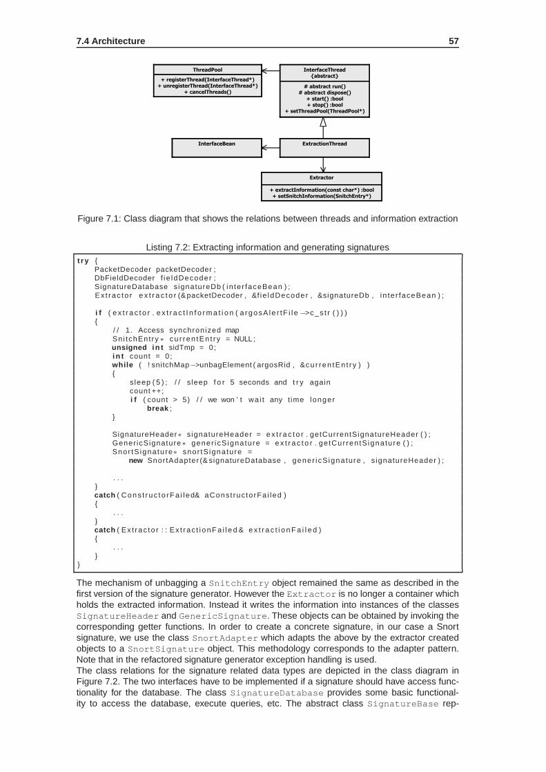
7.4 Architecture 57
# abstract run()# abstract dispose()
+ start() :bool+ stop() :bool
+ setThreadPool(ThreadPool*)
InterfaceThread{abstract}
# abstract run()# abstract dispose()
+ start() :bool+ stop() :bool
+ setThreadPool(ThreadPool*)
InterfaceThread{abstract}
+ registerThread(InterfaceThread*)+ unregisterThread(InterfaceThread*)
+ cancelThreads()
ThreadPool
+ registerThread(InterfaceThread*)+ unregisterThread(InterfaceThread*)
+ cancelThreads()
ThreadPool
ExtractionThreadExtractionThread
+ extractInformation(const char*) :bool+ setSnitchInformation(SnitchEntry*)
Extractor
+ extractInformation(const char*) :bool+ setSnitchInformation(SnitchEntry*)
Extractor
InterfaceBeanInterfaceBean
Figure 7.1: Class diagram that shows the relations between threads and information extraction
Listing 7.2: Extracting information and generating signaturest r y {
PacketDecoder packetDecoder ;DbFieldDecoder f ie ldDecoder ;SignatureDatabase signatureDb ( in te r faceBean ) ;Ex t rac to r e x t r a c t o r (& packetDecoder , &f ie ldDecoder , &signatureDb , in te r faceBean ) ;
i f ( e x t r a c t o r . e x t r a c t I n f o r m a t i o n ( a rgosA l e r tF i l e −>c_s t r ( ) ) ){
/ / 1 . Access synchronized mapSni tchEnt ry ∗ cu r ren tEn t r y = NULL ;unsigned i n t sidTmp = 0;i n t count = 0 ;while ( ! snitchMap−>unbagElement ( argosRid , &cu r ren tEn t r y ) ){
s leep ( 5 ) ; / / s leep f o r 5 seconds and t r y againcount ++;i f ( count > 5) / / we won ’ t wa i t any t ime longer
break ;}
SignatureHeader∗ signatureHeader = e x t r a c t o r . getCurrentSignatureHeader ( ) ;Gener icSignature∗ gener icS ignature = e x t r a c t o r . ge tCur ren tS ignature ( ) ;Snor tS ignature∗ snor tS ignature =
new SnortAdapter (& signatureDatabase , gener icS ignature , s ignatureHeader ) ;
. . .}catch ( Cons t ruc to rF a i led& aConst ruc to rFa i led ){
. . .}catch ( Ex t rac to r : : Ex t rac t i onF a i l e d & e x t r a c t i o n F a i l e d ){
. . .}
}
The mechanism of unbagging a SnitchEntry object remained the same as described in thefirst version of the signature generator. However the Extractor is no longer a container whichholds the extracted information. Instead it writes the information into instances of the classesSignatureHeader and GenericSignature. These objects can be obtained by invoking thecorresponding getter functions. In order to create a concrete signature, in our case a Snortsignature, we use the class SnortAdapter which adapts the above by the extractor createdobjects to a SnortSignature object. This methodology corresponds to the adapter pattern.Note that in the refactored signature generator exception handling is used.The class relations for the signature related data types are depicted in the class diagram inFigure 7.2. The two interfaces have to be implemented if a signature should have access func-tionality for the database. The class SignatureDatabase provides some basic functional-ity to access the database, execute queries, etc. The abstract class SignatureBase rep-

58 CHAPTER 7. REFACTORING THE SIGNATURE GENERATOR
+ saveToDatabase() throw(CorrelationRequiredException&,CorrelationCandidatesException&) :bool
<<interface>>SignatureSaveToDatabase
+ saveToDatabase() throw(CorrelationRequiredException&,CorrelationCandidatesException&) :bool
<<interface>>SignatureSaveToDatabase
SignatureDatabaseSignatureDatabaseSignatureBaseAccessToDatabase{abstract}
SignatureBaseAccessToDatabase{abstract}
SignatureBase{abstract}
SignatureBase{abstract}
+ loadFromDatabase(unsignedint signatureId) :bool
<<interface>>SignatureLoadFromDatabase
+ loadFromDatabase(unsignedint signatureId) :bool
<<interface>>SignatureLoadFromDatabase
SnortAdapterSnortAdapter
GenericSignatureGenericSignatureSnortSignatureSnortSignature
SignatureHeaderSignatureHeader
Figure 7.2: The class relations for the signature related data types
resents the abstract type of a signature. Each signature has to be related to an instance ofSignatureHeader. This class represents the head of a signature and is used to identify asignature. The class SignatureBase together with the two interfaces build an abstract sig-nature with database capability. Classes for a Snort and a generic signature are derived fromit. The Snort signature class has a subclass which can be used to adapt a generic signa-ture to a Snort signature. Note that the classes SignatureHeader, GenericSignature andSnortSignature have a database table counterpart. The database table definitions can befound in the appendix G. As the signature generator is under ongoing development the tablesstill may be altered.
7.5 Supported signatures
If the extractor is started it tries to get as much information as possible. But if e.g. no Tracker logfile is available the packet identifier may not be complete. Then a weaker signature is created.Subsequently the different possible Snort signatures are listed.
Signature with LCS byte string:
alert tcp any any -> any 21 (content:"|05 D3 FF 00 09 A4 C6 12|";)
Signature with string packet identifier and LCS string:
alert tcp any any -> any 21 (content:"USER"; content:"|09 A4 C612|";)
Signature with type field packet identifier and LCS string:
alert tcp any any -> any 21 (byte_test: 4, =, 2, 70; content:"|09 A4C6 12|";)

7.6 Evaluation 59
Signature with an open-ended protocol field:
alert tcp any any -> any 21 (content:"USER"; dsize:>32;)
Signature with string packet identifier and token-ended var iable-length field:
alert tcp any any -> any 21 (content:"USER"; content:!"|0D 0A|";offset: 5; depth: 465;)
Signature with type field packet identifier and variable-len gth field specified by anotherfield:
alert tcp any any -> any 21 (byte_test: 4, =, 2, 70; byte_test: 4,>, 450, 66;)
Two possible signatures have been omitted because they follow from the last two presentedsignatures. The first one consists of a string identifying the message type and a variable-lengthfield specified by another field. The second signature omitted consists of a binary field identifyingthe message type and a content string of variable length.
7.6 Evaluation
7.6.1 Measuring signature generation performance
For estimating the average delay for generating a signature ten different test runs have beendone for four distinct attacks recognized by Argos. The measurements have been done offline.For measuring the signature generation delay the same methodolgy has been used as for theTracker evaluation; performance measurement can be enabled by using a precompiler directiveto set the variable PERFORMANCE_MEASUREMENT. Figure 7.3 depicts the test runs. The mea-sured delay incorporates both the information extraction and the adaption of the generic signa-ture to a Snort signature. From the graphic the average delay for the generation of a signaturecan be rated to about 850 milliseconds. Note that parsing the log file of the Tracker, correlatingthe Tracker log files with information from Argos and the inter-process communication with thereporting thread of the Tracker is not incorporated in these measures as they do not belong tothe actual signature generation. On the other hand the time needed for initializing the NetPDLlibrary is included in these measures. Parsing the XML file of the NetPDL protocol definitionscertainly has a major part of the overall delay for generating a signature. The delays showngive an idea of the induced delay by the signature generation. However, the delay may changesignificantly if any of the above tasks are incorporated or omitted in the signature generation.

60 CHAPTER 7. REFACTORING THE SIGNATURE GENERATOR
Figure 7.3: The delays for generating different signatures

Chapter 8
Conclusions and Outlook
8.1 Results
In this section the potential of our signatures is compared to some approaches presented inthe chapter 3. The NoAH infrastructure filters network traffic very thoroughly before it gets tothe containment system. Still more important, Argos only raises an alert when an attack actuallytook place. In this case it provides us with precise information about the system state. If the con-dition leading to the alert can be mapped to a network packet we have a richness of informationthat can be used to describe the attack that has occurred. Currently we use this informationto describe precisely which application has a buffer overflow vulnerability and how it can beexploited. This approach for protecting server applications selectively from buffer overflow ex-ploits is of inestimable value. Productive server systems crucial to failures can be protected fromzero-day exploits if the NoAH infrastructure is able to observe the appropriate exploit first.There are a few approaches with a containment system similar to Argos like e.g. TaintCheck [13]or Vigilante [20]. TaintCheck however creates very weak string-based signatures out of its ex-tracted attack information. Vigilante creates its own format of self-certifying signatures. Anotherinteresting approach is COVERS [37]. It pursues a signature generation mechanism similar toours in that after detecting an attack the victim’s process memory is compared to recent inputdata. A drawback of this approach seems to be that parsing input data after correlation withmemory depends on a special message format language. Remember that specifying dozens ofprotocols by ourselves would be inefficient and error-prone. Instead we rely on the NetPDL pro-tocol library. Furthermore with the tracker framework we have not only protocol-field knowledgebut even protocol-state knowledge. The position-aware distribution signatures (PADS) systempresented in [36] produces signatures based on byte-frequency distributions. These type of sig-nature however can not be transformed into a Snort signature. Systems like Autograph [9] orPAYL [16] generate signatures based on byte strings. These signatures normally implicate highfalse positives and are not capable of detecting altered attack code.It is reemphasized that there are mainly two mechanisms that contribute to a signature’s qual-ity. The first one is the type of attack detection that is used to extract relevant information forsignature generation. The second aspect is the type of signature that is used to represent theextracted information. It is important not to mistake the above signature type with a concretesignature format. The latter is just a transformation of the former into a representation compliantwith an existing signature format, e.g. the Snort signature format.
8.2 Conclusions
The first mandatory subtask of this thesis was to design, implement and evaluate an applicationprotocol plugin for the application state tracking framework. The evaluation has shown that therequirements have been fulfilled and the implementation was successful. The plugin has beentested for memory leaks with different tools such as valgrind and memprof and showed no sig-nificant runtime dependent problems. Performance tests have shown an average delay inducedby the FTP plugin for processing packets about 26 microseconds. This delay corresponds toa one-digit percentage compared to the overall delay for processing a packet with the Tracker.
61

62 CHAPTER 8. CONCLUSIONS AND OUTLOOK
The correct functioning of the state machine has been approved theoretically and practically bysimulated FTP conversations.A simple signature generator correlating information from Argos and the tracker framework hasbeen designed, implemented and demonstrated at a NoAH meeting. The generated signaturesand the capabilities of the generation mechanism however remained at a proof-of-concept level.From the PoC implementation of the above two subtasks different observations have beenmade. The most important observations are summarized below.
• Reliability and accuracy of the generated signatures were not a question of the chosenconcrete signature format, in our case the Snort format. Rather the difficulty was to extractprecise and reliable information and map the information into internal representations thatcan be used by a SGM.
• Signature evaluation is a hard topic and is at least questionable in our case of only exem-plarily available exploits.
• The initial design of the signature generator was too inflexible with respect to the inter-nal representation of signature properties and the signatures themselves. This led to athorough redesign of the entire signature generation component.
• The architecture of the tracker framework proved as inflexible too. The hardcoded proto-col plugins were not accurate. From this and the preceding arguments a more genericapproach for protocol state tracking, signature generation and further purposes evolved.
The redesigned architecture for generating signatures creates attack signatures in a flexiblymanner. The complexity and accuracy of the generated signatures depend on information thatwas extracted from both the honeypot network and a Tracker log. If the detected attack is abuffer overflow which was triggered by abusing a single protocol field, the false-positives rate forthese signatures is almost zero since the signatures describe the characteristics of the bufferoverflow vulnerability. If for some reasons the extracted information is incomplete, emergencysignatures are generated, e.g. based on byte strings. This assures that we always generatea valid signature. Due to different methods for extracting attack information we are capable ofpredicting the quality of the generated signatures during information extraction.
8.3 Outlook
In summary a system for automated signature generation imposes a large effort and resultsin a complex system. Flexibility and generic configurability are the catchwords for such a sys-tem. What about a design that only knows generic ”properties”? Each property is configuredby a specification language and tells the information extractor how it is extracted. From thisset of properties another specification would tell an adapter how to transform different proper-ties in order to synthesize a specific and concrete signature, e.g. for the Snort IDS as in ourcase. Whereas this suggestion is not in the scope of this thesis more immediate but small tasksshould be done first. The appendix H contains a categorized list of todo’s for the current archi-tecture. The most important steps will be to thoroughly finish the signature generator and adda state tracking action component for the generic state machine. Different details have to beclarified such as what happens if a protocol field is stream-based and the field data could bedistributed over several network packets. What has to be done to support signature generationfor reassembled packets? Are there any drawbacks when relying on the NetBee library? Howcould the design get adapted for other possible attack types except the supported buffer over-flows, e.g. format string exploits? These questions or subtasks are just an assortment and thelist could be expanded arbitrarily.

Appendix A
NoAH core components:Extraction and Processing ofattack information
In this chapter the different information available from both, Argos and the Tracker, is explained.Illustrations help to clarify which component provides which information. In the first section theinitial state of information extraction for attacks is described. In the following section the effectsof this thesis on the information extraction and processing are depicted.
A.1 Initial attack information
Argos detects when tainted data is about to be executed or used as an operand for an in-struction. In this case of remote code execution the network packet from which the tainted dataoriginated is identified. Furthermore the position of the tainted data in the appropriate packet isdetermined. Summarized, Argos provides information about the system’s state, e.g. a memorydump, the set of processor register values as well as the network packet and data therein re-sponsible for triggering an attack alert. Figure A.1 illustrates the information provided by Argos.The snitch perl script tells us which application was attacked on which platform. The purpose of
Memory Dump
ArgosNetwork Packet
04 F2 A6 00
Tainted data which is
about to be used in
instruction execution
Position
in
network
packet
Snitch Perl Script
- Operating system
- Attacked service / program
Argos II
04 F2 A6 00
Figure A.1: Information provided by the containment system Argos
the Tracker is to provide us with information additional to the one given by Argos. It mainly hasinformation about the packet fields and protocols contained in a network packet and in whichstate the corresponding protocols have been for this network packet. Note that this informationcould be extracted also on demand. This means that we could inspect a packet history just
63

64APPENDIX A. NOAH CORE COMPONENTS: EXTRACTION AND PROCESSIN G OF
ATTACK INFORMATION
when an alert is raised instead of tracking the packets before they arrive at Argos. However, thishas the drawback that the time needed to generate a signature increases significantly. FigureA.2 depicts the two sources for information about the attack, Argos and the Tracker. In the initial
Memory Dump
ArgosNetwork PacketTracker
04 F2 A6 00
IP
TCP
04 F2 A6 00
Dest Address
Src Address
Dest PortSrc Port
Protocol Field Knowledge
Protocol Connection State:
TCP: Connection established
Tainted data which is
about to be used in
instruction execution
Position
in
network
packet
Snitch Perl Script
- Operating system
- Attacked service / program
Argos II
Figure A.2: Additional packet information provided by the tracker framework
state no application protocol plugin was implemented. If Argos points to a position inside thenetwork packet which belongs to an application protocol field, no information about the protocolwould be available at this time.
A.2 Current state of attack information extraction
After implementing a FTP plugin for the Tracker it was possible to fully decode packets con-taining an attack for the FTP protocol. Figure A.3 depicts this situation. At a later point in time
Memory Dump
ArgosNetwork PacketTracker
04 F2 A6 00
IP
TCP
Dest Address
Src Address
Dest PortSrc Port
Protocol Field Knowledge
Protocol Connection State:
TCP: Connection established
Tainted data which is
about to be used in
instruction execution
Position
in
network
packet
Snitch Perl Script
- Operating system
- Attacked service / program
Argos IIFTP
User name argument
“USER”
04 F2 A6 00
Figure A.3: FTP protocol knowledge by a Tracker plugin
the Tracker plugins have been substituted by the NetBee library and a generic state machine.However the situation depicted remains the same. In figure A.4 the current process of attackinformation extraction is illustrated. In a first step we use the network packet identified by Argoswhich was the origin for the tainted data triggering the attack. Comparing the network packethistory from the Tracker and Argos we can find the same packet in the Tracker network logfile. Applying an LCS algorithm on the network packet and the memory dump of Argos allowsus to extract a byte string. This byte string can be used for signature generation in case moresophisticated signature generation fails. The network packet in the Tracker log file is then used

A.2 Current state of attack information extraction 65
ArgosSignature GeneratorTracker
Network Packet(in Tracker Network Logfile)
Packet Entry(in Tracker Logfile)
Signature
Byte string(with LCS algorithm)
Packet Information(addresses, ports,...)
State Information
Packet Identifier
Vulnerable Field
Network Packet(Origin of Tainted Data)
Memory Dump
Position of Tainted Datain Network Packet
Find
LCS
Find
Extract
Find
LCS
Find
Figure A.4: Overview of the information extraction process
to find its related entry in the second Tracker log file. This second log file contains all the infor-mation extracted by the plugins. Out of the packet log entry information about the packet canbe extracted. Information about the protocols, their fields and connection states is available. Apacket identifier tells us how this network packet is identified, e.g. by containing a certain string.At last the position of the tainted data triggering the attack alert is used to locate the vulnerableprotocol field.

66APPENDIX A. NOAH CORE COMPONENTS: EXTRACTION AND PROCESSIN G OF
ATTACK INFORMATION

Appendix B
Glossary
In this glossary the most important terms from the field of computer networking and securityare explained. The term explanations do not intend to qualify for completeness. They rathershould give an idea of the corresponding terms. Most of the definitions are taken from theWikipedia online encyclopedia1. Some definitions may have been reworked or supplementedwith additional information.
Activation zone Where the payload is executed. It produces output events (indicating that thedesired outcome of an attack has occurred) and feedback events (that theattacker can determine whether an attack was successful).
Address SpaceRandomization
Despite the wide publicity received by buffer overflow attacks, a vast ma-jority of today’s security vulnerabilities continue to be caused by memoryerrors, with a significant shift away from stack-smashing exploits to newerattacks such as heap overflows, integer overflows, and format-string attacks.Address space randomization hinders some types of security attacks by pre-venting an attacker being able to easily predict target addresses. For exam-ple attackers trying to execute return-to-libc attacks must locate the code tobe executed; while other attackers trying to execute shellcode injected onthe stack have to first find the stack. In both cases, the related memory ad-dresses are obscured from the attackers; these values have to be guessed,and a mistaken guess is not usually recoverable due to the application crash-ing.
Attack A principal is able to gain unauthorized access to a computer system or todisrupt its operation in an unintended way. An attack is the exploitation ofexisting bugs.
Attack vector Every interface is a possible vector of attack, e.g. user interface, I/O interface,physical or network interfaces etc.
Computer worm A computer worm is a self-replicating computer program. It uses a network tosend copies of itself to other nodes on the network and it may do so withoutany user intervention. Unlike a virus, it does not need to attach itself to anexisting program. Worms always harm the network and if only by consum-ing bandwidth, whereas viruses always infect or corrupt files on a targetedcomputer.
1http://en.wikipedia.org/
67
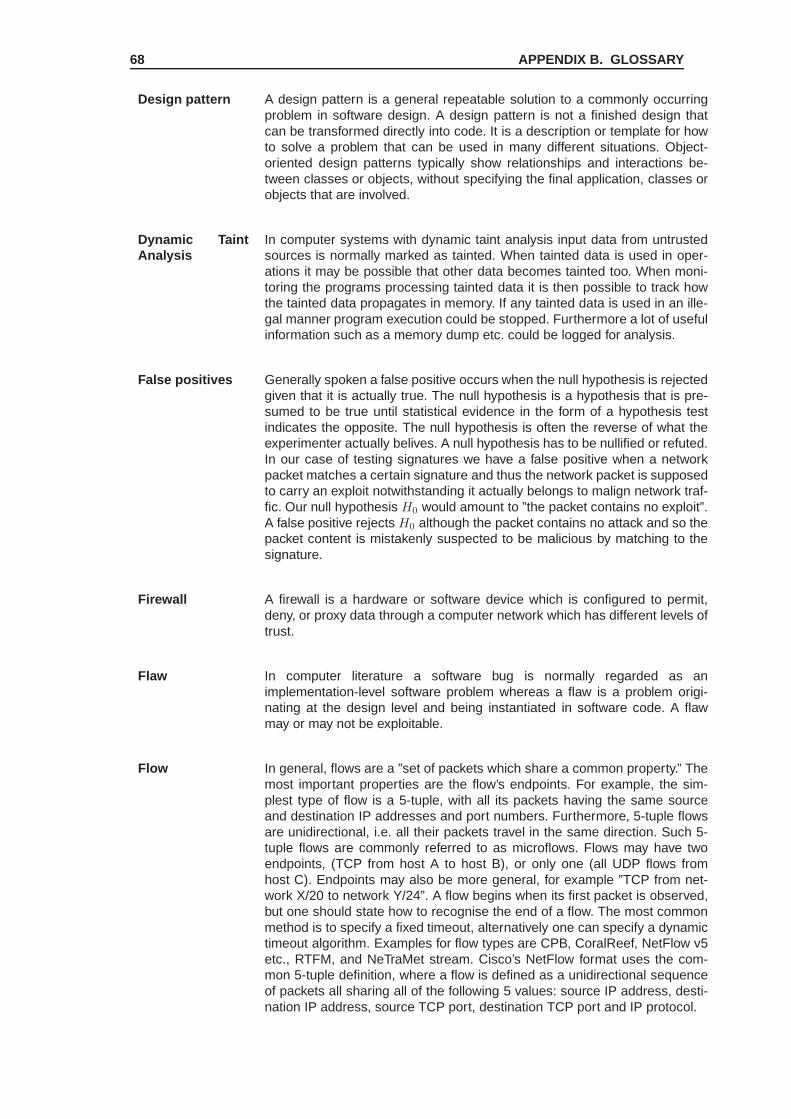
68 APPENDIX B. GLOSSARY
Design pattern A design pattern is a general repeatable solution to a commonly occurringproblem in software design. A design pattern is not a finished design thatcan be transformed directly into code. It is a description or template for howto solve a problem that can be used in many different situations. Object-oriented design patterns typically show relationships and interactions be-tween classes or objects, without specifying the final application, classes orobjects that are involved.
Dynamic TaintAnalysis
In computer systems with dynamic taint analysis input data from untrustedsources is normally marked as tainted. When tainted data is used in oper-ations it may be possible that other data becomes tainted too. When moni-toring the programs processing tainted data it is then possible to track howthe tainted data propagates in memory. If any tainted data is used in an ille-gal manner program execution could be stopped. Furthermore a lot of usefulinformation such as a memory dump etc. could be logged for analysis.
False positives Generally spoken a false positive occurs when the null hypothesis is rejectedgiven that it is actually true. The null hypothesis is a hypothesis that is pre-sumed to be true until statistical evidence in the form of a hypothesis testindicates the opposite. The null hypothesis is often the reverse of what theexperimenter actually belives. A null hypothesis has to be nullified or refuted.In our case of testing signatures we have a false positive when a networkpacket matches a certain signature and thus the network packet is supposedto carry an exploit notwithstanding it actually belongs to malign network traf-fic. Our null hypothesis H0 would amount to ”the packet contains no exploit”.A false positive rejects H0 although the packet contains no attack and so thepacket content is mistakenly suspected to be malicious by matching to thesignature.
Firewall A firewall is a hardware or software device which is configured to permit,deny, or proxy data through a computer network which has different levels oftrust.
Flaw In computer literature a software bug is normally regarded as animplementation-level software problem whereas a flaw is a problem origi-nating at the design level and being instantiated in software code. A flawmay or may not be exploitable.
Flow In general, flows are a ”set of packets which share a common property.” Themost important properties are the flow’s endpoints. For example, the sim-plest type of flow is a 5-tuple, with all its packets having the same sourceand destination IP addresses and port numbers. Furthermore, 5-tuple flowsare unidirectional, i.e. all their packets travel in the same direction. Such 5-tuple flows are commonly referred to as microflows. Flows may have twoendpoints, (TCP from host A to host B), or only one (all UDP flows fromhost C). Endpoints may also be more general, for example ”TCP from net-work X/20 to network Y/24”. A flow begins when its first packet is observed,but one should state how to recognise the end of a flow. The most commonmethod is to specify a fixed timeout, alternatively one can specify a dynamictimeout algorithm. Examples for flow types are CPB, CoralReef, NetFlow v5etc., RTFM, and NeTraMet stream. Cisco’s NetFlow format uses the com-mon 5-tuple definition, where a flow is defined as a unidirectional sequenceof packets all sharing all of the following 5 values: source IP address, desti-nation IP address, source TCP port, destination TCP port and IP protocol.

69
Honeypot A honeypot is a trap set to detect, deflect or in some manner counteractattempts at unauthorized use of information systems. Generally it consists ofa computer, data or a network site that appears to be part of a network butwhich is actually isolated, (un)protected and monitored, and which seemsto contain information or a resource that would be of value to attackers. Ahoneypot is valuable as a surveillance and early-warning tool. While often acomputer, a honeypot can take on other forms, such as files or data records,or even unused IP address space. Honeypots should have no productionvalue and hence should not see any legitimate traffic or activity. Whateverthey capture can then be surmised as malicious or unauthorized.
Injection vector Describes the format of an input-driven attack. Each target environment im-poses certain restrictions on how an attack must be formatted. The goal ofthe injection vector is to place the attack payload into a target activation zone.They comprise truly generic rules for formatting an attack.
Intrusion detec-tion system
An intrusion detection system is used to detect many types of maliciousnetwork traffic and computer usage that can not be detected by a conven-tional firewall. This includes network attacks against vulnerable services,data driven attacks on applications, host based attacks such as privilegeescalation, unauthorized logins and access to sensitive files, and malware(viruses, trojan horses, and worms). An IDS is composed of several compo-nents: Sensors which generate security events, a Console to monitor eventsand alerts and control the sensors, and a central Engine that records eventslogged by the sensors in a database and uses a system of rules to generatealerts from security events received. There are several ways to categorize anIDS depending on the type and location of the sensors and the methodologyused by the engine to generate alerts. In many simple IDS implementationsall three components are combined in a single device or appliance.
Intrusion preven-tion system
An intrusion prevention system is a computer security device that monitorsnetwork and/or system activities for malicious or unwanted behavior and canreact, in real-time, to block or prevent those activities. Network-based IPS,for example, will operate in-line to monitor all network traffic for maliciouscode or attacks. When an attack is detected, it can drop the offending pack-ets while still allowing all other traffic to pass. Intrusion prevention technologyis considered by some to be an extension of intrusion detection (IDS) tech-nology.
Network AddressTranslation
In computer networking, the process of network address translation (NAT,also known as network masquerading, native address translation or IP mas-querading) involves re-writing the source and/or destination addresses of IPpackets as they pass through a router or firewall. Most systems using NATdo so in order to enable multiple hosts on a private network to access theInternet using a single public IP address.
Open SystemsInterconnection(OSI) model
The open systems interconnection basic reference model (OSI referencemodel or OSI model for short) is a layered, abstract description for com-munications and computer network protocol design, developed as part ofthe open systems interconnection (OSI) initiative. It is also called the OSIseven layer model. A layer is a collection of related functions that providesservices to the layer above it and receives service from the layer below it.For example, a layer that provides error-free communications across a net-work provides the path needed by applications above it, while it calls thenext lower layer to send and receive packets that make up the contents ofthe path. The seven layers as defined by the OSI model ordered from thetop are application, presentation, session, transport, network, data link andphysical layer.

70 APPENDIX B. GLOSSARY
Polymorphicworm
Polymorphic code is code that mutates while keeping the original algorithmintact. This technique is often used by computer viruses, shellcodes andcomputer worms to hide their presence. A polymorphic worm uses the tech-nique of polymorphic code mutation. Polymorphic algorithms make it difficultfor such software to locate the offending code as it constantly mutates. En-cryption is the most commonly used method of achieving polymorphism incode. However, not all of the code can be encrypted as it would be com-pletely unusable. A small portion of it is left unencrypted and is used tojumpstart the encrypted software. Anti-virus software targets this small un-encrypted portion of code.
Proxy server A proxy server is a server (a computer system or an application program)which services the requests of its clients by forwarding requests to otherservers. A client connects to the proxy server, requesting some service, suchas a file, connection, web page, or other resource, available from a differentserver. The proxy server provides the resource by connecting to the specifiedserver and requesting the service on behalf of the client. A proxy server mayoptionally alter the client’s request or the server’s response, and sometimesit may serve the request without contacting the specified server.
Software bug A software bug (or just "bug") is an error, flaw, mistake, failure, or fault in acomputer program that prevents it from behaving as intended (e.g., produc-ing an incorrect result). Most bugs arise from mistakes and errors made bypeople in either a program’s source code or its design, and a few are causedby compilers producing incorrect code.
Software exploit An exploit is a piece of software, a chunk of data, or sequence of commandsthat take advantage of a bug, glitch or vulnerability in order to cause unin-tended or unanticipated behavior to occur on computer software, hardware,or something electronic (usually computerized).
Telnet protocol Telnet (Teletype Network) is a network protocol used on the Internet or localarea network (LAN) connections. The initial protocol specification can befound in RFC 854. The introduction therein describes the purpose of theprotocol in the following way: ”The purpose of the Telnet Protocol is to providea fairly general, bi-directional, eight-bit byte oriented communications facility.Its primary goal is to allow a standard method of interfacing terminal devicesand terminal-oriented processes to each other.”
Virus A computer virus is a computer program that can copy itself and infect a com-puter without permission or knowledge of the user. The original may modifythe copies or the copies may modify themselves, as occurs in a metamor-phic virus. A virus can only spread from one computer to another when itshost is taken to the uninfected computer, for instance by a user sending itover a network or carrying it on a removable medium such as a floppy disk,CD, USB drive or by the Internet. Additionally, viruses can spread to othercomputers by infecting files on a network file system or a file system that isaccessed by another computer. Viruses are sometimes confused with com-puter worms and Trojan horses. A worm can spread itself to other computerswithout needing to be transferred as part of a host, and a Trojan horse is afile that appears harmless until executed.

Appendix C
The original tracker framework
In this chapter the components and their functions of the Tracker framework will be presented.Furthermore the skeletons of important functions will be sketched.
C.1 Component overview
There coexist multiple threads in the Tracker. The functionality is divided into components eachcorresponding to a single thread. The explanation of the functionality will be split into twophases, the initialization phase and the packet processing phase.
The initialization phase
Figure C.1 illustrates the components and functions participating during the initialization ofthe Tracker. The main function first reads the configuration file. According to the configura-
Main Process
Initialize dynamiclibrary plugins
Readconfiguration file
Start the statetracking threads
Initializecapturing routine
via pcap
Start pcapcapturing loop,
callback handle isthe functiondispatcher()
State Tracking Threads
stateTracker()
Start reportingthread
Plugin Stack
Plugin 1:initFunction()
Plugin 2:initFunction()
Plugin n:initFunction()
State Tracking Thread n
State Tracking Thread 2
State Tracking Thread 1
trackerConfig.xml
Figure C.1: The initialization phase of the Tracker
tion settings the desired number of state tracking structures is created. Each state trackingstructure gets its own plugin stack. As mentioned in chapter 2 the plugins are initialized bycalling initFunction. When the data structures have been created the reporting thread willbe started. Following the state tracking threads are started. These threads remain inside thefunction stateTracker and wait for incoming messages from the dispatcher function inthe main process.
71

72 APPENDIX C. THE ORIGINAL TRACKER FRAMEWORK
The packet processing phase
The Packet Processing phase is depicted in Figure C.2. When a packet arrives at the state
Capturing Thread
Dispatcher()callback handle
NetworkNetwork
Socket
IPC
File I/O
TrackerOutput.dat
TrackerDump.dat
Pcap packetcapturing loop
getThreadId()
Statetracking Thread n
Reporting Thread
Plugin 1:entryFunction()
Plugin 2:entryFunction()
Plugin n:entryFunction()
stateTracker()message loop
Figure C.2: The packet processing phase of the Tracker
tracking host the pcap packet capturing loop will create some data structures and invoke thecallback function dispatcher. Inside the dispatcher function the packet is analyzed and ifthe packet belongs to an already registered network connection the network packet is sent viamessage passing to the appropriate state tracking thread. If no network connection can be foundfor the received packet a new connection for this packet will be registered and assigned to a ran-domly chosen thread. The packet receiving thread invokes the first plugin by calling its functionentryFunction and passes the network packet by reference. Each plugin is responsible toforward the network packet to the next appropriate plugin when it has done its processing steps.When no suitable plugin is found anymore in the plugin stack the state tracking loop will pass areporting buffer to the reporting thread and wait for new network packets. The reporting threaditself will write the received buffer to a log file betimes.
C.2 Components and their algorithms
In this section the basic functionality of the most important functions of the Tracker frameworkis presented. For an overview of the entire set of functions and a short description refer to thegenerated source code documentation. The source listings are not complete. They rather intendto allow the reader being able to orient easier in the Tracker source code.
Main Process
The most important steps done in the Main Process are illustrated in Figure C.1. The listing C.1shows the code corresponding to the illustrated steps during initialization.
Listing C.1: The most important steps in the Main Process/ / Read c o n f i g u r a t i o n f i l econf igData a l l Con f i gDa ta = scanConf igF i le ( f i l e ) ;
/ / I n i t i a l i z e dynamic l i b r a r y p l ug i nsi n i tDynami cL i b ra ry (& a l l Con f i gDa ta ) ;
/ / S t a r t the r e p o r t i n g threadaReportingThread =i n i tRepo r t i ngT h read(& stateTrackerThreads [ 0 ] . outgoingMessageQueue ,&a l l Con f i gDa ta ) ;
/ / S t a r t the s ta te t r a c k i n g threadsstateTrackerThreads = i n i tS ta teT racke rT h reads(& a l l Con f i gDa ta ) ;
/ / I n i t i a l i z e cap tu r i ng rou t i necaptureHandle = i n i t C a p t u r e ( a l l Con f i gDa ta . device , f i l t e r _ e x p ) ;
/ / Global a v a i l a b l e i n fo rma t i on used by s ta te t r a c k i n g threads

C.2 Components and their algorithms 73
dispatcherExtraArguments someDispatcherExtraArguments ;someDispatcherExtraArguments . captureHandle = captureHandle ;someDispatcherExtraArguments . a l l Con f i gDa ta = &a l l Con f i gDa ta ;someDispatcherExtraArguments . connect ions = &connect ions ;someDispatcherExtraArguments . fragmentedPackets =&fragmentedPackets ;someDispatcherExtraArguments . stateTrackerThreads =stateTrackerThreads ;
/ / Reg is te r necessary s i gna l handlers . . .
/ / S t a r t pcap cap tu r i ng loop wi th d ispa tcher ( ) as ca l l backpcap_loop ( captureHandle ,−1 , d ispa tcher , ( u_char ∗ )(& someDispatcherExtraArguments ) ) ;
If a packet is captured by the pcap library the callback function dispatcher is invoked. ListingC.2 shows the most important code sequences for this function.
Listing C.2: Conceptual code excerpt for the function dispatcher
/ / Get the necessary g l oba l a v a i l a b l e i n fo rma t i onsomeDispatcherExtraArguments = ( s t ruc t dispatcherExtraArgument ∗ ) ( args ) ;
/ / Determine the i d o f the app rop r i a te s ta te t r a c k i n g thread/ / and re tu rn a reassembled packet i f necessaryIPConnection∗ reassembledPacket = getLocalThreadIdByPacket ( pkthdr ,
packet , someDispatcherExtraArguments , threadIdOfConnect ion ) ;
i f ( threadIdOfConnect ion != −1) {/ / se l ec t the corresponding s ta te t racke r thread f o r t h i s connect ionstateTrackerThread ∗aStateTrackerThread =
someDispatcherExtraArguments−>stateTrackerThreads + threadIdOfConnect ion ;
i f ( reassembledPacket ){
/ / take i n f o from reassembled packet i f i t e x i s t s}else{
/ / normal , not fragmented packet}
memcpy ( message . msgText , &newPacket , sizeof ( newPacket ) ) ;messageQueueSend( aStateTrackerThread−>incomingMessageQueue ,
&message , sizeof ( newPacket ) ) ;} else {
/ / The packet a r r i ved i s e i t h e r not supported or i t has been on ly a fragment ./ / In the l a t t e r case the loca lThreadId i s re tu rned on ly a f t e r the t ime the/ / l a s t frame has a r r i ved and the packet could be reassembled .
}
The function responsible for reassembling network packets if necessary and to deter-mine if the packet already belongs to a registered network connection is the functiongetLocalThreadIdbyPacket. The basic steps executed in this function are listed in listingC.3.
Listing C.3: Conceptual code excerpt for the function getLocalThreadIdByPacket
/ / dec la re po i n te rs to packet headers
/ / de f ine e therne t header
/ / de f ine / compute i p header o f f s e t
/ / de le te e n t r i e s o f the IPkey map which are o l de r than FRAGMENTATION_TIMEOUT
/ / i f fragmented , t h a t means more−fragments−f l a g i s se t and / or fragment o f f s e t !=0
/ / process packet ∗ // / save the e s s e n t i a l data ( source port , d e s t i n a t i o n po r t ) i n case of TCP / UDP
/ / c rea te connectionKey / I d e n t i f i e rconnectionKey ∗ connKey ;i f ( ipHeader−>i p_s rc . s_addr ==

74 APPENDIX C. THE ORIGINAL TRACKER FRAMEWORK
someDispatcherExtraArguments −>a l lConf igData−>monitoredHostIpAddress . s_addr ) {connKey = new connectionKey ( ipHeader−>i p_ds t . s_addr ,∗ srcpor t ,∗ des tpo r t ) ;
} else i f ( ipHeader−>i p_ds t . s_addr ==someDispatcherExtraArguments −>a l lConf igData−>monitoredHostIpAddress . s_addr ) ) {connKey = new connectionKey ( ipHeader−>i p_s rc . s_addr ,∗ destpor t ,∗ s rcpo r t ) ;
}
/ / Try to f i n d the en t r y i n the connect ion map.connectionMap : : i t e r a t o r connect ionMapIter =
someDispatcherExtraArguments −>connections −>f i n d (∗connKey ) ;
i f ( connect ionMapIter == someDispatcherExtraArguments−>connections −>end ( ) ){
/ / the connect ion en t r y i s not i n the map, the re fo re we add i t
/ / assign a random threadId , get the timestamp and/ / add the new connect ion to the mapaConnection−>loca lThreadId =
rand ( ) % someDispatcherExtraArguments −>a l lConf igData−>numOfStateTrackerThreads ;connect ionEntry anEntry (∗ connKey , aConnection ) ;someDispatcherExtraArguments −>connections −>i n s e r t ( anEntry ) ;
/ / se t the i t e r a t o r to the new en t r yconnect ionMapIter = someDispatcherExtraArguments −>connections −>f i n d (∗connKey ) ;
}th readId = connect ionMapIter−>second−>loca lThreadId ;return reassembledPacket ;
State Tracking Threads
The functionality of the state tracking threads is resided in the function stateTracker. Eachthread just awaits messages from the dispatching process and processes them. The code skele-ton looks as shown in listing C.4.
Listing C.4: The code skeleton for the state tracking thread loop stateTracker
void ∗ s ta teT rack i ng : : s ta teTracker ( void ∗ p t r ) {while ( ! f i n i s h ){
messageQueueReceive ( th isThread−>incomingMessageQueue , &readBuffer , . . . )switch ( readBuf fe r . msgType){
case MSQ_TYPE_IP_MESSAGE:{
do{
d l e r r o r ( ) ;p l u g i n _ t i p = i pPro toco l−>ent ryFunct ion ;r e t = i p ( . . . ) ;i f ( r e t == EXIT_FAILURE ){
/∗ Report b u f f e r i s dumped ∗ /}else{
/∗ Plug ins successfu l ∗ //∗ Append new en t r y i n repo r t b u f f e r ∗ /
}msgsnd ( th isThread−>outgoingMessageQueue )
} while ( )}
}}
}
The state tracking threads invoke the first suitable plugin by calling its entry function. Eachprotocol is then responsible to call a succeeding plugin. The entry function mandatory to beimplemented by each protocol plugin should follow the concept as shown in listing C.5.
Listing C.5: Program code guideline for the mandatory entryFunction/ / Ex t rac t i n fo rma t i on o f preceding p ro toco l

C.2 Components and their algorithms 75
/ / Process the packet f o r the cu r ren t p ro toco l/ / and e . g . update s ta te machine etc .
/ / Report
/ / Give packet to the next p ro toco l
/ / Always re tu rn success , even i f the packet had wrong formati n t re tu rnVa lue = EXIT_SUCCESS;
/ / The f indSubPro toco l f u n c t i o n searches i n the subProtocolMap/ / f o r an en t r y w i th the key moni toredHostPort
p ro toco l ∗ nextPro toco l = th i sPro toco l −>f indSubPro toco l ( moni toredHostPort ) ;i f ( nex tPro toco l && nextPro toco l−>ent ryFunct ion ) {
re tu rnVa lue = nextPro toco l−>ent ryFunct ion ( nextHeader ,packetLength−SIZE_UDP_HEADER, NULL, nextPro toco l ,th i sS ta teT racke r , l as tRepo r tbu f fe r −>next , packet ) ;
}
return re tu rnVa lue ;

76 APPENDIX C. THE ORIGINAL TRACKER FRAMEWORK

Appendix D
Techniques in SignatureGeneration Mechanisms
The following presented techniques have been used in one or more signature generation mech-anisms presented in this documentation. If not specified explicitly the main source can assumedto be http://en.wikipedia.org.
D.1 Byte-Frequency Distribution (BFD)
The byte frequency distribution is a function fp(b), which describes the probability for b to appearat position p. b is between 0 and 255. The sum of fp(b) for all possible bytes (the values from0 to 255) is 1. If W is the width in bytes of the signature, (f1, f2, . . . , fW ) represents a simplesignature based on BFDs.
D.2 Longest Common Substring (LCS) problem
The longest common substring problem is to find the longest string (or strings) that is a substring(or are substrings of) two or more strings. It should not be confused with the longest commonsubsequence problem. You can find the lengths and starting positions of the longest commonsubstrings of S and T in O(n + m) with the help of a generalised suffix tree. Finding them bydynamic programming costs O(nm). The solutions to the generalised problem take O(n1 + . . .+nK) and O(n1 · · · . . . · · ·nK) time.
D.3 Longest Common Subsequence (LCSeq) problem
The problem of the longest common subsequence (LCSeq) is to find a longest sequence whichis a subsequence of all sequences in a set of sequences (often just two). The problem is some-times defined to be finding all longest common subsequences. The problem is NP-hard for thegeneral case of an arbitrary number of input sequences. When the number of sequences isconstant, the problem is solvable in polynomial time by dynamic programming.
D.4 N-Gram analysis
N-Grams are used to describe objects as vectors. This makes it possible to apply geometric,statistical and other mathematical techniques on objects although the techniques are only de-fined for vectors.Definition: A is an alphabet and |A| is the cardinal number of the alphabet. Let n be an integer.An N-gram is a word of length n.If you determine the number of occurrences of an N-gram within a possible sequence of char-acters of an alphabet you get a N-gram frequency vector for this sequence. For comparing two
77

78 APPENDIX D. TECHNIQUES IN SIGNATURE GENERATION MECHANIS MS
such vectors you could for instance apply the Manhattan, Cosine or Euclidian distance. Anothermetric is the Z-score.
D.4.1 Z-score
In statistics, a standard score (also called z-score or normal score) is a dimensionless quantityderived by subtracting the population mean from an individual (raw) score and then dividingthe difference by the population standard deviation. The z-score reveals how many units of thestandard deviation a case is above or below the mean. If the mean and deviation can not beknown then may be one could assume that the subject is normally distributed.
D.4.2 Dice coefficient
A prominent algorithm to compute a similarity between words is the Dice algorithm. The Dicecoefficient of two terms a and b is defined by:
d(a, b) = 2|Γ(a)∩Γ(b)||Γ(a)|+|Γ(b)|
where Γ(x) is a N-gram decomposition of the term d. d is between 0 and 1.An example:Let Term a = ”wirk” and Term b = ”work”. If we use Tri-grams the decomposition looks as follows:
Γ(a) = {w, wi, wir, irk, rk, k} and Γ(b) = {w, wo, wor, ork, rk, k}
The Dice coefficient is d(wirk, work) = 2···36+6 = 0.5. So you can say the similarity is 50 percent.
D.5 Expectation-Maximization (EM) algorithm
An expectation-maximization (EM) algorithm is used in statistics for finding maximum likelihoodestimates of parameters in probabilistic models, where the model depends on unobserved la-tent variables. EM alternates between performing an expectation (E) step, which computes anexpectation of the likelihood by including the latent variables as if they were observed, and amaximization (M) step, which computes the maximum likelihood estimates of the parameters bymaximizing the expected likelihood found on the E step. The parameters found on the M stepare then used to begin another E step, and the process is repeated.
D.6 Clustering
Cluster Analysis1, also called data segmentation, has a variety of goals. All relate to groupingor segmenting a collection of objects (also called observations, individuals, cases, or data rows)into subsets or "clusters", such that those within each cluster are more closely related to oneanother than objects assigned to different clusters. Central to all of the goals of cluster analysis isthe notion of degree of similarity (or dissimilarity) between the individual objects being clustered.There are two major methods of clustering, hierarchical clustering and k-means clustering.
D.6.1 Hierarchical clustering
In hierarchical clustering the data are not partitioned into a particular cluster in a single step.Instead, a series of partitions takes place, which may run from a single cluster containing allobjects to n clusters each containing a single object. Hierarchical Clustering is subdivided intoagglomerative methods, which proceed by series of fusions of the n objects into groups, anddivisive methods, which separate n objects successively into finer groupings.
1from http://www.resample.com/xlminer/help/HClst/HClst_intro.htm

D.7 Rabin fingerprint 79
D.7 Rabin fingerprint
The Rabin fingerprinting scheme is a method for implementing public key fingerprints usingpolynomials over a finite number of elements. Given an n-bit message m0, ..., mn−1, we view itas a polynomial of degree n − 1:
f(x) = m0 + m1x + ... + mn−1xn−1
We then pick a random irreducible polynomial p(x) of degree k, and we define the fingerprint ofm to be
f(x) mod p(x)
which can be viewed as a polynomial of degree k − 1 or as a k-bit number.For further information consider the original document about the Rabin fingerprint [29]. [4] givesan overview of applications of the above presented fingerprinting method.
D.8 Bayes law
The Bayes law is a result in probability theory, which relates the conditional and marginal proba-bility distributions of random variables. In some interpretations of probability, the Bayes law tellshow to update or revise beliefs in light of new evidence a posteriori.The probability of an event A conditional on another event B is generally different from the prob-ability of B conditional on A. However, there is a definite relationship between the two, and theBayes law is the statement of that relationship, as described by the following formula:
P (A | B) =P (B | A)P (A)
P (B)
D.9 Content-based Payload Partitioning
The COPP algorithm is based on Rabin fingerprints that searches for repeated byte sequencesby partitioning the payload into content blocks. This enables the description of payload contentthat is tolerant of payload variability to some degree. The algorithm has been developed for theAutograph project [9] and is performed after accumulating enough number of suspicious flowsto partition the payloads into variable-length chunks of content blocks.

80 APPENDIX D. TECHNIQUES IN SIGNATURE GENERATION MECHANIS MS
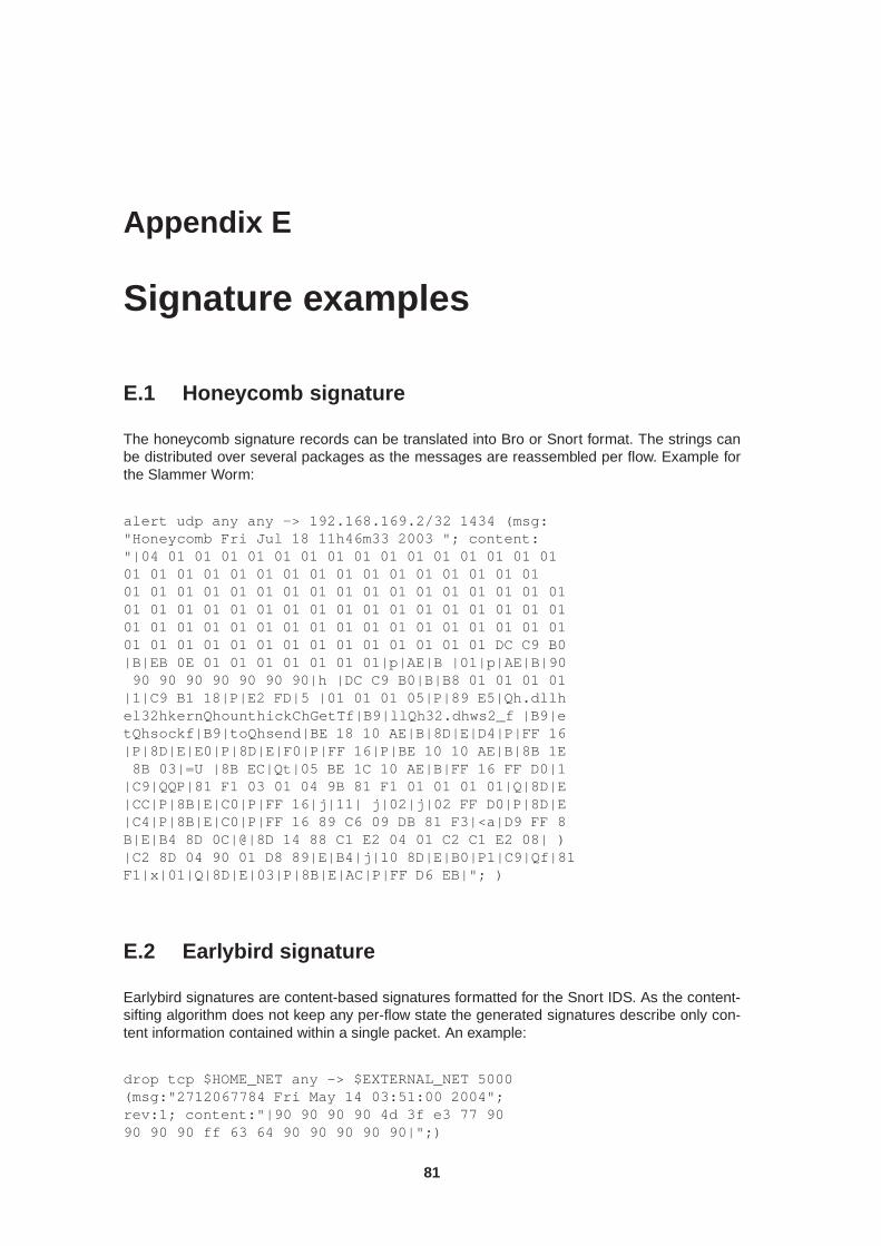
Appendix E
Signature examples
E.1 Honeycomb signature
The honeycomb signature records can be translated into Bro or Snort format. The strings canbe distributed over several packages as the messages are reassembled per flow. Example forthe Slammer Worm:
alert udp any any -> 192.168.169.2/32 1434 (msg:"Honeycomb Fri Jul 18 11h46m33 2003 "; content:"|04 01 01 01 01 01 01 01 01 01 01 01 01 01 01 0101 01 01 01 01 01 01 01 01 01 01 01 01 01 01 0101 01 01 01 01 01 01 01 01 01 01 01 01 01 01 01 0101 01 01 01 01 01 01 01 01 01 01 01 01 01 01 01 0101 01 01 01 01 01 01 01 01 01 01 01 01 01 01 01 0101 01 01 01 01 01 01 01 01 01 01 01 01 01 DC C9 B0|B|EB 0E 01 01 01 01 01 01 01|p|AE|B |01|p|AE|B|9090 90 90 90 90 90 90|h |DC C9 B0|B|B8 01 01 01 01
|1|C9 B1 18|P|E2 FD|5 |01 01 01 05|P|89 E5|Qh.dllhel32hkernQhounthickChGetTf|B9|llQh32.dhws2_f |B9|etQhsockf|B9|toQhsend|BE 18 10 AE|B|8D|E|D4|P|FF 16|P|8D|E|E0|P|8D|E|F0|P|FF 16|P|BE 10 10 AE|B|8B 1E8B 03|=U |8B EC|Qt|05 BE 1C 10 AE|B|FF 16 FF D0|1
|C9|QQP|81 F1 03 01 04 9B 81 F1 01 01 01 01|Q|8D|E|CC|P|8B|E|C0|P|FF 16|j|11| j|02|j|02 FF D0|P|8D|E|C4|P|8B|E|C0|P|FF 16 89 C6 09 DB 81 F3|<a|D9 FF 8B|E|B4 8D 0C|@|8D 14 88 C1 E2 04 01 C2 C1 E2 08| )|C2 8D 04 90 01 D8 89|E|B4|j|10 8D|E|B0|P1|C9|Qf|81F1|x|01|Q|8D|E|03|P|8B|E|AC|P|FF D6 EB|"; )
E.2 Earlybird signature
Earlybird signatures are content-based signatures formatted for the Snort IDS. As the content-sifting algorithm does not keep any per-flow state the generated signatures describe only con-tent information contained within a single packet. An example:
drop tcp $HOME_NET any -> $EXTERNAL_NET 5000(msg:"2712067784 Fri May 14 03:51:00 2004";rev:1; content:"|90 90 90 90 4d 3f e3 77 9090 90 90 ff 63 64 90 90 90 90 90|";)
81
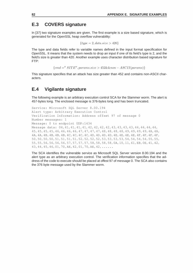
82 APPENDIX E. SIGNATURE EXAMPLES
E.3 COVERS signature
In [37] two signature examples are given. The first example is a size based signature, which isgenerated for the OpenSSL heap overflow vulnerability:
{type = 2, data.size > 420}
The type and data fields refer to variable names defined in the input format specification forOpenSSL. It means that the system needs to drop an input if one of its field’s type is 2, and thefield’s size is greater than 420. Another example uses character distribution based signature forFTP:
{cmd =′′ SITE′′, params.size > 452&&non− ASCII(params)}
This signature specifies that an attack has size greater than 452 and contains non-ASCII char-acters.
E.4 Vigilante signature
The following example is an arbitrary execution control SCA for the Slammer worm. The alert is457-bytes long. The enclosed message is 376-bytes long and has been truncated.
Service: Microsoft SQL Server 8.00.194Alert type: Arbitrary Execution ControlVerification Information: Address offset 97 of message 0Number messages: 1Message: 0 to endpoint UDP:1434Message data: 04,41,41,41,41,42,42,42,42,43,43,43,43,44,44,44,44,45,45,45,45,46,46,46,46,47,47,47,47,48,48,48,48,49,49,49,49,4A,4A,4A,4A,4B,4B,4B,4B,4C,4C,4C,4C,4D,4D,4D,4D,4E,4E,4E,4E,4F,4F,4F,4F,50,50,50,50,51,51,51,51,52,52,52,52,53,53,53,53,54,54,54,54,55,55,55,55,56,56,56,56,57,57,57,57,58,58,58,58,0A,10,11,61,EB,0E,41,42,43,44,45,46,01,70,AE,42,01,70,AE,42,......
The SCA identifies the vulnerable service as Microsoft SQL Server version 8.00.194 and thealert type as an arbitrary execution control. The verification information specifies that the ad-dress of the code to execute should be placed at offest 97 of message 0. The SCA also containsthe 376 byte message used by the Slammer worm.

Appendix F
Installation manual for theapplication state tracker framework
The application state tracker framework is a standalone application which tracks the state ofvarious network protocols up to the application layer. In this manual the installation procedureand the configuration of the Tracker is described. Because it was written to work in conjunctionwith Argos, also tips for installation and configuration of the latter are provided. The tracker in-terface (actually the identical component as the Signature Generator ) links the Tracker to Argosand is briefly presented. For a more thorough description of installing the entire set of NoAHcomponents, especially Argos, refer to the document ”How to set up the NoAH infrastructure?”which is provided on the NoAH project homepage as part of the deliverable 2.2, http://www.fp6-noah.org/publications/deliverables/D2.2/index.html.
F.1 The tracker framework
F.1.1 Installing the tracker framework
The tracker framework is a standalone application tracking the state of various network protocolsup to the application layer. The installation is not yet automated but rather straightforward. Thefollowing points have to be done for a proper installation:
1. Make sure you have a version of the libpcap [18] installed. The tracker framework has beentested with the version 0.8 of libpcap. This library is used for capturing the raw networkpackets and is used by various other projects in the network domain, e.g. by Wireshark(former Ethereal). To install libpcap under Debian and Ubuntu Linux Distributions followthese steps:
(a) Download and install the library: apt-get install libpcap0.8
(b) As the Tracker is looking for the library libpcap.so, we have to create a link with thisname to the libpcap version we want to use,e.g. ln /usr/lib/libpcap.so.0.8 /usr/lib/libpcap.so
The installation of the libpcap will be quite similar on other Linux distributions.
2. Copy the Tracker files into a folder.
3. If you compile the Framework the first time, type autoreconf -i
4. Start the configuration script: ./configure
5. Run the Makefiles: make
83

84APPENDIX F. INSTALLATION MANUAL FOR THE APPLICATION STATE T RACKER
FRAMEWORK
F.1.2 Configuration of the tracker framework
The Tracker is configured by a configuration file named trackerConfig.xml. Later versionsof the Framework will allow configuration files specified by the user. A DTD (Document TypeDefinition) specification of the XML file will follow. The configuration file first defines some pa-rameters for the tracker framework itself. The number of state-tracking threads for instanceallows to improve the utilization of multicore-processors or multiprocessor systems. Then thenetwork protocols available as plugins for the framework are declared. A protocol can haveother subprotocols attached. Note that the current version of the Tracker is able to monitor onlyone host, i.e. packets are only examined if they belong to a connection with the monitored hostas source or destination port.
F.2 Qemu, Argos and the Interface
Because the tracker framework is meant to work with Argos, we describe the installation andconfiguration of Qemu, the tracker interface and Argos itself in this section.
F.2.1 Qemu
Qemu [26] is a processor emulator which allows full virtualization of computer systems. In con-junction with the NoAH project Qemu is used to create working image partitions of guest op-erating systems which will be then able to run with Argos. We won’t use Argos for the instal-lation of the guest operating systems because Argos slows down the operating system due toits dynamic tainted analysis (DTA). To install Qemu download the latest archive at the projectpage and unzip it. Type ./configure, make and make install. Qemu is now located in/usr/local. Building Qemu may not work with the Gnu compiler gcc version 4.xx. Insteaduse 3.xx. E.g. change the symbolic link gcc in /usr/bin from gcc-4.1 to gcc-3.4.
KQemu accelerator
It is recommended to additionally use the Qemu accelerator KQemu. It can be downloaded atthe project page of Qemu. Unzip the archive, run ./configure, make and make install.This will install KQemu into /usr/local. To run the kernel module kqemu the following com-mands can be used:
1. /bin/mknod /dev/kqemu c 250 0
2. /bin/chmod 666 /dev/kqemu
3. /sbin/modprobe kqemu
The Qemu version has to support the accelerator module. You can check this with the output ofthe configure script in the directory of Qemu. In the output it should say kqemu support yes.
Installing a Guest Operating System
To install a guest operating system from a cd-rom or an image the following steps are necessary:
1. qemu-img create myOS.img 5GB
2. qemu -hda myOS.img -cdrom /dev/cdrom or myImage.iso -boot d
The first command creates an empty image file with a size of 5 gigabytes. The second commandstarts Qemu with myOS.img as local harddisk. Because we want to mount myImage.iso fromwhere we install the guest operating system, we use the -cdrom option. The -boot d optiontells Qemu not to boot from hda but from the cdrom.The cdrom option can also be used to mount software into the guest OS. If you want to createan image of a directory you can use
mkisofs -D -iso-level 3 -joliet-long -l -o directory.img-no-iso-translate -allow-multidot -U directory

F.2 Qemu, Argos and the Interface 85
The content of the directory is now stored in the image directory.img. This image can bemounted with Qemu: qemu -hda myOS.img -cdrom directory.img. Now the operatingsystem in myOS.img can access directory.img as a cd-rom drive.
Providing more memory for the Guest OS
If you want to use more memory for the guest OS use the following commands:
• umount /dev/shm
• mount -t tmpfs -o size=528m none /dev/shm
The last command allows us to set the memory to 512 megabytes by starting Qemu with qemu-m 512 .... We have set the size to 528 mb because the tmpfs should always be slightlybigger than the memory size used for the guest OS.
F.2.2 Argos
The Tracker is part of a project called NoAH (Network of Affined Honeypots) and thus is meantto work in conjunction with other programs although it can be run independently. The core ofthe NoAH project is a honeypot system based on the virtual machine Qemu. This system calledArgos allows the detection of remote code execution through dynamic tainted analysis (DTA).How to set up Argos and other related topics are described in the documentation section onthe project page of Argos [8]. The installation steps in a nutshell: Download the latest Argosarchive, unzip and compile it by running ./configure -prefix=/opt/argos, make andmake install. This will install Argos into the directory /opt/argos. If you want to use Ar-gos with the state tracker framework you will have to add the option -enable-net-trackerto the configure script. If Argos is too slow and consumes too much memory you can add-enable-lowmem as option to the configure script.
F.2.3 Networking
There exist various howto’s in the internet for how to set up networking capabilities within Qemuand Argos respectively. A common way is to use a virtual bridge. But with this configurationyou won’t be able to connect from the guest OS to the outside world except to the host OS.To achieve full NAT-alike networking functionality you will have to combine both bridging and IPforwarding / NAT. In this section we will explain the idea of bridging and virtual interfaces. Furtherwe provide the reader with some simple shell scripts which set up a network environment forArgos and Qemu respectively. The guest OS however will not be able to contact hosts exceptthe host OS. At www.linuxforen.de you can find a german howto for Qemu and networkingvia IP forwarding1. A configuration manual for bridged networking with IP forwarding will followat a later time.
Ethernet bridging A virtual bridge allows you to interconnect network devices like it is donewhen using real bridges. Additional to the functionality of a pure switch the bridge ker-nel module gives you the opportunity to filter packets. For further information look athttp://linux-net.osdl.org/index.php/Bridge.
Tap / Tun interface Tun is a virtual point-to-point network device. It was designed as low levelkernel support for IP tunneling. For user applications there are two interfaces: /dev/tunX(character device) and tunX (virtual point-to-point interface). Tap is the same virtual deviceas Tun but instead provides support for Ethernet tunneling. The two interfaces for userapplications are: /dev/tapX and tapX.The idea is that a user application can write a packet (Ethernet or IP frame) to the virtualdevice /dev/tunX and the kernel will receive the frame from the tunX interface. The otherway around the kernel writes to the tunX interface and the user application reads from/dev/tunX. Thus these virtual network devices (Tap / Tun) can receive packets from auser space program instead from a physical network interface. And the other way around
1http://www.linuxforen.de/forums/showthread.php?p=939854#post939854

86APPENDIX F. INSTALLATION MANUAL FOR THE APPLICATION STATE T RACKER
FRAMEWORK
they send packets to user space applications instead of to a physical network interface.The kernel itself handles the packets like they came from real physical devices. A goodstarting point for further information is http://vtun.sourceforge.net/tun/faq.html.
Combination of bridging and the tap interface Because we want to have access to networkdevices via Argos and no one should realize that there is a host OS, we first build a bridgeon our host OS. This way the emulated OS will access the network via the bridge andwill not see the guest OS. But this is only possible if we additionally assign a virtual tapinterface to Argos through which it can communicate with the kernel of the host OS.
Preconditions
• Make sure your kernel supports bridging and virtual interfaces (tun). This can be checkedby typing grep CONFIG_TUN .config and grep CONFIG_BRIDGE .config in thedirectory /usr/src/<your linux kernel version>. These two options should beincluded statically or as modules, e.g. CONFIG_BRIDGE=m.
• The following packets have to be installed: bridge-utils, SDL library and headers
Starting Emulation with Network Support
If we have met above preconditions we will be able to start Qemu or Argos with network support.The following scripts are necessary:
qemu-ifup A script which automates the procedure of setting up the bridge and the virtualinterface (appendix F.4.1).
qemu-ifdown A script which removes the created bridge and interfaces (appendix F.4.2).
start-argos A script which starts Argos (appendix F.4.3). Starting Qemu works similar.
When we have started the guest OS do not forget to configure the guest OS too. The presentedscript in F.4.1 explains how it works.
F.2.4 Tracker interface
The tracker interface links the tracker framework to Argos. When Argos detects an attack theInterface is notified via a socket. The Interface sends a signal to the Tracker and the latter dumpsits outputs. In the Tracker output the network packets which have caused Argos to produce analarm are then identified by the Interface.
Installation
The interface needs the cargos-lib which can be downloaded at the project homepage of Argos[8]. For the installation run autoreconf -i, ./configure and make. In some deliverablesthe Interface is part of the tracker framework in that it is contained as a subfolder of the frame-work. Then autoreconf will not only create the necessary files for the Tracker but also for theInterface. The makefile of the Tracker may then also invoke the makefile of the Interface.
Database setup
Because the interface uses a MySQL database to store information about the generated signa-tures, you have to first make sure that you have a version of MySQL server installed on one ofyour hosts. The access credentials are later added to the configuration file of the interface asmentioned in the next section. If you have a running version of MySQL server use the followingcommands to set up the signature database:
• mysql -uuser -ppassword -hyourhost
• mysql> CREATE DATABASE signatureDB;

F.3 Putting the Pieces Together 87
• mysql> signatureDB < signature_database.sql;
• mysql> exit;
Note that you have to replace the access credentials for user, password and host according toyour settings in the first of the above listed commands.
Configuration
The interface is configured by the file configI.xml. In this configuration file we have to set theIP at which we can connect to Argos through the control socket. With our network configurationthis IP corresponds to the IP of the bridge. The .netlog file of Argos will be located from whereArgos is started. So be aware when setting the path to the netlog file, that Argos will have to bestarted from the same directory. It is recommended to use a dedicated directory from where tostart Argos because all session related files will then be held in a separate place. The outputand the dump file of the Tracker will be located in the Tracker directory.
F.3 Putting the Pieces Together
After the successful installations of all software components we can use our scripts to run eitherQemu or Argos. Use Qemu for the installation of guest operating systems and for the installationof additional software. When we have our desired guest OS setup, we start Argos for attackdetection, preferably not as root. At last we start the Tracker and the Interface.
F.4 Ready-to-use Scripts
F.4.1 Qemu-ifup
Listing F.1: Script for bridge configuration, place it in /etc# ! / b in / bash#place i t i n the f o l d e r / e t c /
################################## The br idge#################################
c l e a r
echo / / / / / / / / / / / / / / / / / / / / / / / / / / / / / / / / /echo / / Conf igur ing the br idge . . .echo / / / / / / / / / / / / / / / / / / / / / / / / / / / / / / / / /
i f i f c o n f i g br0then
echo Bridge br0 e x i s t s a l ready .sudo i f c o n f i g br0 192.168.3.55 # The br idge gets th i s IP address
elseecho Bridge br0 does not e x i s t yet , I am c r e a t i n g i t now .# adds a br idge br0sudo b r c t l addbr br0# br idge br0 wi th 192.168.3.55 i s the gateway for the guest OS . . .sudo i f c o n f i g br0 192.168.3.55
f iecho Bridge−IP−Address : 192.168.3.55
################################## The v i r t ua l i n t e r f a c e#################################
echo / / / / / / / / / / / / / / / / / / / / / / / / / / / / / / / / / / / / / / / / / / /echo / / Conf igur ing the v i r t u a l i n t e r f a c e $1 . . .echo / / / / / / / / / / / / / / / / / / / / / / / / / / / / / / / / / / / / / / / / / / /
# $1 i s the ifname−argument from argos ( for us tun1 )# The br idge connects to the guest OS v ia th i s IP# The guest OS i t s e l f doesn ’ t know t h i s and j u s t sees eth0 . . .sudo i f c o n f i g $1 192.168.3.50sudo b r c t l a d d i f br0 $1 # adds the i n t e r f a c e $1 to the br idge br0echo The i n t e r f a c e $1 gets the IP 192.168.3.50
echo / / / / / / / / / / / / / / / / / / / / / / / / / / / / / / / / / / / / / / / / / / / / / / / / / / / / / / / / / / / /echo / / Conf igura t ion at the Guest OS:echo / / Network−C o n t r o l l e r IP : 192.168.3.51 − Host IPecho / / Defau l t Gateway IP : 192.168.3.55echo / / Note : The v i r t u a l tap i n t e r f a c e i s not addressed hereecho / / / / / / / / / / / / / / / / / / / / / / / / / / / / / / / / / / / / / / / / / / / / / / / / / / / / / / / / / / / /
e x i t 0

88APPENDIX F. INSTALLATION MANUAL FOR THE APPLICATION STATE T RACKER
FRAMEWORK
F.4.2 Qemu-ifdown
Listing F.2: Script for removing virtual interfaces, place it in /etc# ! / b in / bashsudo / sb in / i f c o n f i g br0 downsudo / sb in / i f c o n f i g $1 downsudo / usr / sb in / b r c t l d e l i f br0 $1sudo / usr / sb in / b r c t l de lb r br0
F.4.3 Start-argos
Listing F.3: Script that starts Argos with network capability# ! / b in / sh
# wi thout the next l i ne , the mouse won ’ t workexport SDL_VIDEO_X11_DGAMOUSE=0
# wi thout the next l i ne , t here would be a warning because of the frequencysudo sh −c ’ echo 1024 > / proc / sys / dev / r t c /max−user−f r e q ’
# set access permissionssudo chmod 666 / dev / net / tun
# wi thout the next l i ne , you have to s t a r t argos as r o o t ( on ly on kerne l >2.6 .??)sudo t u n c t l −u user −t tap0
# s t a r t argos , snapshot modeargos −m 256 −hda /home / user / DiplomaThesis / images / win2kEN . img −net nic , v lan=0−net tap , v lan =0 , i fname=tap0 , s c r i p t = / e t c /qemu−i f u p −win2k −csaddr 192.168.2.55
#shutdown i n t e r f a c e/ e tc / qemu−i fdown

Appendix G
Signature Database
Table signatureHeaderField name Data type Description
sigNo int unsigned, primary,auto-increment
The primary key which uniquely identifies a signatureand its header. Every signature must have a header.
revision smallint unsigned If the signature was improved the revision number isincreased.
osType smallint unsigned The numerical type of operating system for this sig-nature.
moduleName text The name of the application that should be pro-tected.
attackType smallint unsigned The type of attack the signature is describing.
protocol tinytext The protocol name according to the correspondingentry in the NetPDL database.
field tinytext The vulnerable protocol field name according to theentry in the NetPDL database.
lastModification datetime The timestamp of the last modification of this signa-ture.
Table G.1: Database table outline for signature headers
89

90 APPENDIX G. SIGNATURE DATABASE
Table signatureDetailsField name Data type Description
sigNo int unsigned, primary This foreign key points to the signatureHeader table.
transportProto tinytext The textual description of the transport protocol.
srcPort smallint unsigned The application source port.
destPort smallint unsigned The application destination port.
flowDirection smallint Numerical value of the packet direction.
flowState smallint Numerical value of the connection state.
eipString tinytext The overwritten EIP value if any in text form.
rawEipNetworkPacketOffset intunsigned
The offset of the EIP from the beginning of the net-work packet.
rawEipApplicationPayloadOffsetint unsigned
The offset of the EIP from the beginning of the appli-cation payload.
rawApplicationPayloadOffsetint unsigned
The offset of the application payload in the networkpacket.
lcsString text A byte string created with the LCS method that canbe used to identify the attack in the network packet.
lastModification datetime The timestamp of the last modification of this signa-ture.
Table G.2: Database table outline for detailed signature information
Table packetIdentifierField name Data type Description
sigNo int unsigned, primary This foreign key points to the signatureHeader table.
name tinytext The name of the PDML field declaring the messagetype according to the NetPDL database.
packetIdentificationType small-int unsigned
Numerical value of the identifier type.
string tinytext A string if the message is identified by a string.
specOffset int unsigned The offset of the field specifying the message type.
specWidth int unsigned The width of the message specifying field.
specFieldValue int The value of the field for this message type.
Table G.3: Database table outline for protocol-specific message type identifers

91
Table variableFieldField name Data type Description
sigNo int unsigned, primary This foreign key points to the signatureHeader table.
name tinytext The name of the field with variable length that seemsto be vulnerable.
offset int unsigned The offset of the field.
criticalLength int unsigned The critical field length triggering e.g. a buffer over-flow.
endTokenString tinytext A hexadecimal string if the field is terminated by atoken.
nbFieldType unsigned short The field type according to the NetPDL database.
lengthSpecifyingField tinytext The name of the field specifying the length.
lengthSpecifyingFieldOffset intunsigned
The field offset.
lengthSpecifyingFieldWidth intunsigned
The field width.
lengthMultiplicator smallint A multiplicator for the field value to compute the ac-tual field length.
lengthAddend smallint An addend for the field value.
Table G.4: Database table outline for vulnerable fields of variable length
Table snortSignaturesField name Data type Description
sigNo int unsigned, primary This foreign key points to the signatureHeader table.
revision smallint unsigned The revision of this Snort signature.
content text The Snort signature in text form.
lastModification datetime The timestamp of the last modification of this signa-ture.
Table G.5: Database table outline for Snort signatures

92 APPENDIX G. SIGNATURE DATABASE

Appendix H
TODOs
Old tracker
1. Support offloaded and thus wrong checksums
Signature information extraction
1. Add a signature property for byte frequency distributions (BFD)
2. Support other attack types, especially format strings
3. Improve idea of generic properties for information extraction
Signature Generation
1. Test if packets are encoded
2. Signature for reassembled packets
3. Testing the generic approach with different protocols
4. Stream-based protocols
5. NetBee library constraints and workarounds?
6. Evaluate new Snort signatures
State machine
1. Event data handling in the network protocol state machine framework
2. Adding timeouts for each state to the event processing
3. Implementation of a state tracking action class
93

94 APPENDIX H. TODOS

List of Abbrevations
ASR . . . . . . . . . . . . . . Address Space RandomizationBFD . . . . . . . . . . . . . . Byte Frequency DistributionBNF . . . . . . . . . . . . . . Backus Naur FormCFG . . . . . . . . . . . . . . Control Flow GraphCOPP . . . . . . . . . . . . Content-based Payload PartitioningDFA . . . . . . . . . . . . . . Deterministic Finite-state AutomatonDTA . . . . . . . . . . . . . . Dynamic Taint AnalysisFTP . . . . . . . . . . . . . . File Transfer ProtocolIDS . . . . . . . . . . . . . . . Intrusion Detection SystemIPS . . . . . . . . . . . . . . . Intrusion Prevention SystemISP . . . . . . . . . . . . . . . Internet Service ProviderLCSeq . . . . . . . . . . . . Longest Common SubsequenceLOC . . . . . . . . . . . . . . Lines Of CodeMB . . . . . . . . . . . . . . . Mega bytesNAT . . . . . . . . . . . . . . Network Address TranslationNetPDL . . . . . . . . . . . Network Protocols Description LanguageNIC . . . . . . . . . . . . . . . Network Interface CardNoAH . . . . . . . . . . . . Network of Affined HoneypotsNREN . . . . . . . . . . . . National Research and Education NetworkOSI model . . . . . . . . Open Systems Interconnection (Reference) ModelPDL . . . . . . . . . . . . . . Protocol Declaration LanguagePDML . . . . . . . . . . . . Packet Declaration Markup LanguagePoC . . . . . . . . . . . . . . Proof of ConceptPSML . . . . . . . . . . . . Packet Summary Markup LanguageRFC . . . . . . . . . . . . . . Request For CommentSGM . . . . . . . . . . . . . Signature Generation MechanismSOHO . . . . . . . . . . . . Small Office, Home OfficeSSH . . . . . . . . . . . . . . Secure SHellSTL . . . . . . . . . . . . . . Standard Template LibraryTCP . . . . . . . . . . . . . . Transport Control ProtocolUML . . . . . . . . . . . . . . Unified Modeling Language
95

Index
address space randomization, 27, 63
Bayes law, 24, 75byte frequency distribution, 26, 73
computer worm, 16, 63polymorphic, 24, 66
content-based payload partitioning, 25, 75
dynamic taint analysis, 21, 25, 27, 64
expectation-maximization algorithm, 26, 74
false positives, 16, 64firewall, 15, 64flow, 24, 64
hierarchical clustering, 24, 74honeyd, 20, 24honeypot
high-interaction, 20low-interaction, 20
intrusion detection system, 16, 65intrusion prevention system, 16, 65
Java, 42
longest common subsequence, 24, 73longest common substring, 24, 73
n-gram analysis, 26, 73NetBee library, 49NetPDL, 50NetVM, 50network address translation, 30, 65network processor, 50
OSI model, 30, 65
PDML, 50protocol declaration language, 48protocol knowledge, 47protocol-field knowledge, 16PSML, 50
Rabin fingerprint, 24, 75
self-certifying alerts, 28, 43signature
host-based, 16network-based, 16
signature generation mechanism, 39software bug, 66software exploit, 15, 66
zero-day, 16
TCP checksum offloading, 36Telnet protocol, 30, 66trinity of trouble, 15
virus, 24, 66vulnerability, 15
96

Bibliography
[1] Snort Users Manual.
[2] European Network of Affined Honeypots (NoAH): Attack Detection and Signature Genera-tion, 15 May 2006.
[3] European Network of Affined Honeypots (NoAH): Containment Environment Design, 2006.
[4] A. Broder. Some applications of rabin’s fingerprinting method. In Alfredo De Santis Re-nato Capocelli and Ugo Vaccaro, editors, Sequences II: Methods in Communications, Se-curity, and Computer Science, pages 143–152. Springer-Verlag, 1993.
[5] C. Kreibich and J. Crowcroft. Honeycomb - Creating Intrusion Detection Signatures UsingHoneypots. In 2nd Workshop on Hot Topics in Networks (HotNets-II), 2003.
[6] Christopher Kruegel, Engin Kirda, Darren Mutz, William Robertson, and Giovanni Vigna.Polymorphic Worm Detection Using Structural Information of Executables. 8th Symposiumon Recent Advances in Intrusion Detection (RAID), September 2005.
[7] D. Dagon, X. Qin, G. Gu, W. Lee, J. B. Grizzard, J. G. Levine, and H. L. Owen. Honeystat:Local worm detection using honeypots. In Proceedings of RAID’04, volume 3224, pages39–58. Springer, 2004.
[8] Argos: An Emulator for Capturing Zero-Day Attacks. http://www.few.vu.nl/argos/.
[9] H.-A. Kim and B. Karp. Autograph: Toward Automated, Distributed Worm Signature Detec-tion. In Proceedings of the USENIX Security Symposium, pages 271–286, 2004.
[10] Greg Hoglund and gary McGraw. Exploiting software: how to break code, volume 3.Addison-Wesley, 2004.
[11] Snort Intrusion and Prevention System. http://www.snort.org/.
[12] J. C. Rabek, R. I. Khazan, S. M. Lewandowski, and R. K. Cunningham. Detection of in-jected, dynamically generated, and obfuscated malicious code. In WORM’03: Proceedingsof the 2003 ACM workshop on Rapid Malcode, pages 76–82, New York, NY, USA, 2004.ACM Press.
[13] J. Newsome and D. Song. Dynamic taint analysis for automatic detection, analysis, andsignature generation of exploits on commodity software. In Proceedings of the 12th AnnualNetwork and Distributed System Security Symposium (NDSS), February 2005.
[14] James Newsome, Brad Karp, and Dawn Song. Polygraph: Automatically Generating Sig-natures for Polymorphic Worms. In IEEE Security and Privacy Symposium, 2005.
[15] Jilles Van Gurp and Jan Bosch. On the implementation of Finite State Machines. 3rdAnnual IASTED International Conference Software Engineering and Applications, October1999.
[16] K. Wang and S. J. Stolfo. Anomalous payload-based network intrusion detection. Pro-ceedings of the 7th International Symposium on Recent Advances in Intrusion Detection(RAID), September 2004.
97

98 BIBLIOGRAPHY
[17] L. chung Lam and T. cker Chiueh. Automatic extraction of accurate application-specificsandboxing policy. In Proceedings of the 7th International Symposium in Recent Advancesin Intrusion Detection (RAID), pages 1–20. Springer-Verlag GmbH, September 2004.
[18] The libpcap project. http://sourceforge.net/projects/libpcap/.
[19] Loris Degioanni, Mario Baldi, Diego Buffa, Fulvio Risso, Federico Stirano, and GianlucaVarenni. Network Virtual Machine (NetVM): A New Architecture for Efficient and PortablePacket Processing Applications. In 8th International Conference on Telecommunications,ConTEL, June 2005.
[20] M. Costa, J. Crowcroft, M. Castro, A. Rowstron, L. Zhou, L. Zhang, and P. Barham. Vigi-lante: end-to-end containment of internet worms. In SOSP’05: Proceedings of the twentiethACM symposium on Operating systems principles, pages 133–147, New York, NY, USA,2005. ACM Press.
[21] Marcel Marghitola. Towards exploit signature generation using honeypots ii. Technicalreport, ETH Zurich, Computer Engineering and Networks Laboratory, 2007.
[22] Mario Baldi and Fulvio Risso. A Framework for Rapid Development and Portable Executionof Packet-Handling Applications. 5th IEEE International Symposium on Signal Processingand Information Technology, December 2005.
[23] Mario Baldi and Fulvio Risso. Using XML for Efficient and Modular Packet Processing. InProceedings of IEEE Globecom, December 2005.
[24] Nikita Borisov, David J. Brumley, Helen J. Wang, John Dunagan, Pallavi Joshi, andChuangxiong Guo. A Generic Application-Level Protocol Analyzer and its Language. InThe 14th Annual Network & Distributed System Security Symposium (NDSS), February2007.
[25] NoAH: European Network of Affined Honeypots. http://www.fp6-noah.org/.
[26] Qemu: An open source processor emulator. http://fabrice.bellard.free.fr/qemu/.
[27] Paul Adamczyk. The Anthology of the Finite State Machine Design Patterns. Proceedingsof the Pattern Languages of Programming conference, PLoP, 2003.
[28] The Metasploit project. http://www.metasploit.com/.
[29] Michael O. Rabing. Fingerprinting by random polynomials. Technical report, Center forResearch in Computing Technology, Harvard University, 1981.
[30] Rashid Waraich. Automated Attack Signature Generation: A Survey. Technical report, ETHZurich, Computer Engineering and Networks Laboratory, 2005.
[31] S. Singh, C. Estan, G. Varghese, and S. Savage. Automated Worm Fingerprinting. OSDI,pages 45–60, 2004.
[32] SDL: ITU specification and description language. http://www.sdl-forum.org/sdl/index.htm.
[33] Bro Intrusion Detection System. http://www.bro-ids.org/.
[34] V. Paxson. Bro: a system for detecting network intruders in real-time. Computer Networks,31(23-24):2435–2463, 14 December 1999.
[35] V. Yegneswaran, J. T. Giffin, and S. J. Paul Barford. An architecture for generating semantic-aware signatures. In Proceedings of the 14th USENIX Security Symposium, pages 97–112, August 2005.
[36] Y. Tang and S. Chen. Defending against internet worms: A signature-based approach. InProceedings of IEEE INFOCOM’05, March 2005.
[37] Z. Liang and R. Sekar. Fast and automated generation of attack signatures: A basis forbuilding self-protecting servers. In Proceedings of the 12th ACM Conference on Computerand Communications Security (CCS), November 2005.


![Automated Verification of Practical Garbage Collectors...tractable, we exploit recent advances in automated theorem prov-ing technology, using the Boogie [3] and Z3 [8] tools to provide](https://img.dokumen.tips/doc/110x75/5ed6864bff0e593c0b640190/automated-veriication-of-practical-garbage-collectors-tractable-we-exploit.jpg)