Embed Size (px)
Citation preview

Towards an operating system:
Processes and their
management
64

An operating system’s basic organization
An operating system is organized using the following ideas.
• A number of basic functions that are very dependent on the hardware
of the machine, in particular input/output operations, are provided by
the system.
• The system is a program that works in its own “context” that is kept
completely separate from the “context” of user programs.
• Separating contexts makes it possible to design the system and the
user programs quite independently. These programs are executed in an
interleaved way, simulating a concurrent execution. We will modify the
machine ULg01 in order to enable it to handle traps and interrupts.
65

Interrupts and traps
• To implement a system on a machine, it is necessary to be able to
force execution of the system when needed. This requires special
mechanisms: interrupts and traps.
• An interrupt forces a change in the program being executed when a
given event occurs.
• A trap forces a change in the program being executed when special
instructions, which are not part of the set of instructions defined for
the machine architecture, are used.
• We will modify the machine ULg01 in order to enable it to handle
traps and interrupts.
66
Operating system organization : basic principles
Consider first the situation in which only one user program is active.
• The goal is to share the machine between the user program and a
“system” providing some functionalities, such as input/output
operations, to the user program.
• Execution alternates between the two programs. Switching from the
user program to the system is done:
– At the request of the user program (trap);
– When an interrupt occurs;
– When the user program executes and illegal operation (fault).
These events are collectively called exceptions.
• Switching from the system to the user program is done by the system
when it decides to do so.
67

A shared machine
System
User program
68

Actions to be performed on exceptions
When an exception occurs, one needs to
• Know the address of the system program to be executed,
• Save the return address,
• Save the state of the user program in order to be able to restore this
state when returning form the system.
• When the user program resumes its execution, it finds itself in the
exact same situation it was in when the system was invoked. It is thus
said the the user program operates in its own context.
69

User mode - System mode
• The goal of a system is to avoid the need for the users to cope with
the machine’s details, but it is also to prevent user programs from
blocking the machine or from getting it into in an incoherent state.
• For this goal, some operations must only be possible for the system.
• Two operating modes are thus necessary: a “system” or “supervisor”
mode and a “user” mode in which certain privileged operations are
not possible.
• It is also common to disable interrupts in system mode.
70

The choices of the β architecture
• The instruction with opcode 0x00 is used as system call. Special
instructions with opcode 0x0* can be defined, but are only usable in
supervisor mode.
• The address of the system program to be executed when an exception
occurs is fixed. It can differ depending on the nature of the exception
(interrupt, trap or illegal instruction).
• When switching to the system, the PC of the user program is saved in
register 30, called XP - Exception Pointer
• Bit 31 of the program counter is used to indicate supervisor mode.
• In supervisor mode, interrupts are ignored (have no effect).
71

The machine ULg02
• In ULg02, two new signals are used as input of the microcode ROM:
IRQ and PC31. PC31 is the supervisor mode bit, IRQ is the interrupt
signal coming from the input/output devices.
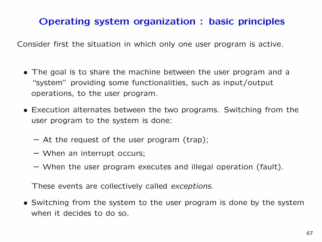
• A new control signal SUPERVISOR appears as output of the microcode.
ROM. It is used to set bit 31 of the program counter.
• In the microcode of ULg02, it is useful to have access to constants.
For this purpose, one adds a ROM in which constants (for example,
the address of the interrupt handler) are kept at positions starting
with the largest ROM address. To control this ROM, two new signals
appear as output of the microcode ROM: LDRMAR and DRROM.
72
ULg02 : a general view
N
3s
CLKLD...
DR...
B
DRALU
CLK A
ALUFunctions
Status flags
LDA
LDPC
DRPC
CLK
I/OOELD
Control Unit
INCPC
OE
LD
PCINC
CLK
LDB
Functions
Status flags
Static RAM
DRSRAMLDSRAM
SMARLDSMAR
LD OE
LDDMAR
OE
DMAR
Dynamic RAM
DRDRAMLD
CLK
LDDRAM
CLK
PCINC
SUPERVISORSUPERVISOR
IRQ
IRQ
RMARLDRMAR
Constants ROM
DRROM
Notice the signal SUPERVISOR and the addition of the constant ROM.
73

ULg02 : the program counter (PC)
LDPC2
0
DRPC
20
90
N20
PCINC
D2...21
LD
3s
CLK
EN D
Q
CLK
SUPERVISOR
PC3120 bits counter
the “privileged bit ” PC31 is implemented explicitly. It can only be set to 1
if the SUPERVISOR signal has value 1.
74
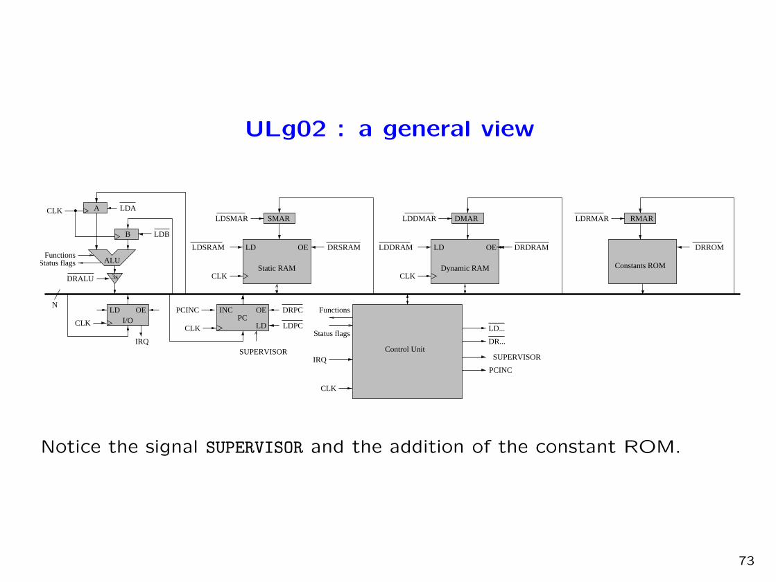
ULg02 : The constant ROM
DRROM
N
LDRMAR8
D0−7
8
88 88
RMAR
OE OE OE OE
CLK
D0...7D24...31
CLK
ROM ROM ROM ROM
The signals controlling the constant ROM are LDRMAR (load ROM address
register) and DRROM (reading from the ROM).
75

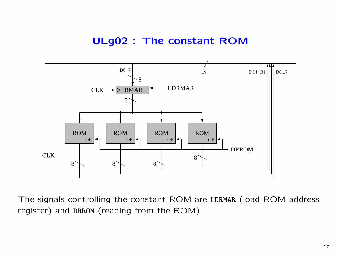
ULg02 : The content of the constant ROM
0x00...
...
0xFA 10000000 00000000 01000000 00000000(Address of the handler “IRQ” — 0x2012)
0xFB 10000000 00000000 00100000 00000000(Address of the handler “Supervisor Call” — 0x2008)
0xFC 10000000 00000000 01100000 00000000(Address of the handler “Illegal Operation” — 0x2016)
0xFD (Address of the handler “Cache Miss Code” — 0x2004)0xFE (Address of the handler “Cache Miss Data” — 0x2000)0xFF 00000000 00000000 11110000 00000000
(Address of register XP)
The addresses of the handlers Cache Miss Code and Cache Miss Data will
be used later for managing virtual memory.
76

ULg02 : the control unit
8
8
6
2
3
55
N
88
4
3
13
1
1
4
8
PCINCALU CinALU Fnct
SUPERVISOR
3
8
8
8
8
16
LDINSTREGLDALDBLDSMARLDDMAR
LDPC
LDSRAMLDDRAM
LDRMAR
DRRcDRRaDRLit/RbDRALUDRSRAMDRDRAMDRPCDRROM
3s 3s 3s 3s3s
3...7 0...20
DRRaDRLit/Rb
Control ROM
ResetPhaseCLK
ALU flags
CLK
END
QDRRc
3...7 0...20
PC31IRQ
LDINSTREG
CLK
EN D
Q
D
Q
D24...31
Instr. 2
Instr. 3
0,1
2...7
5...7
0...4
D8...15 D8...15 D8...15D0...7D16...31
Instr. 1
D0...7
D8...15
Instr. 0CLK
D16...23
D15
The only change is the addition of input (PC31 and IRQ), as well as output
(SUPERVISOR, LDRMAR and DRROM) signals to the microcode ROM.
77
ULg02 : the microcode
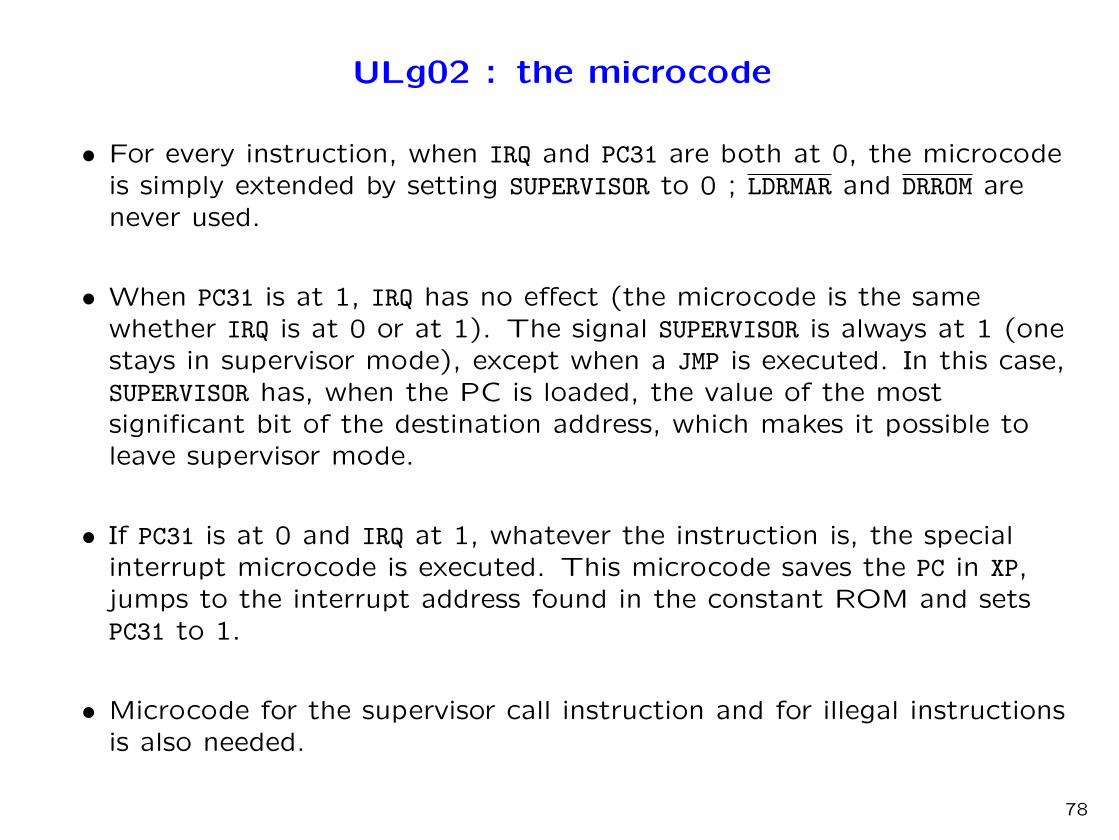
• For every instruction, when IRQ and PC31 are both at 0, the microcodeis simply extended by setting SUPERVISOR to 0 ; LDRMAR and DRROM arenever used.
• When PC31 is at 1, IRQ has no effect (the microcode is the samewhether IRQ is at 0 or at 1). The signal SUPERVISOR is always at 1 (onestays in supervisor mode), except when a JMP is executed. In this case,SUPERVISOR has, when the PC is loaded, the value of the mostsignificant bit of the destination address, which makes it possible toleave supervisor mode.
• If PC31 is at 0 and IRQ at 1, whatever the instruction is, the specialinterrupt microcode is executed. This microcode saves the PC in XP,jumps to the interrupt address found in the constant ROM and setsPC31 to 1.
• Microcode for the supervisor call instruction and for illegal instructionsis also needed.
78

ULg02 : the interrupt microcode
microcode IRQ : IRQ = 1 PC31 = 0 Opcode = ******
Phase Flags Latch ALU LD DR PC+ SVR
flags F,Cin,Mode SEL SEL
0000 * 1 110011 0001 011 0 0 A <- 0xFFFFFFFF
0001 * 1 111111 1000 011 0 0 RMAR <- A
0010 * 1 000000 0011 111 0 0 SMAR <- ROM
0011 * 1 000000 0110 110 0 0 SRAM <- PC
0100 * 1 111110 0001 011 0 0 A <- A-1
0101 * 1 111110 0001 011 0 0 A <- A-1
0110 * 1 111110 0001 011 0 0 A <- A-1
0111 * 1 111110 0001 011 0 0 A <- A-1
1000 * 1 111110 1000 011 0 0 RMAR <- A-1
1001 * 1 000000 0111 111 0 1 PC <- ROM
1010 * 1 000000 0100 110 1 0 DMAR <- PC; PC+
1011 * 1 000000 0000 101 0 0 INSTREG <- DRAM
The saved PC is the one of the instruction following the one that wasabout to be executed when the interrupt occurred. The instruction ataddress XP-4 has thus not been executed.
79
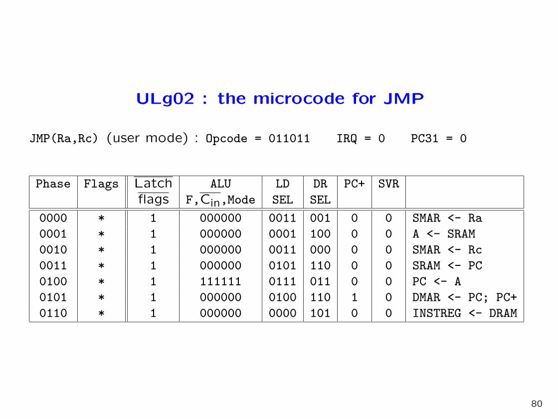
ULg02 : the microcode for JMP
JMP(Ra,Rc) (user mode) : Opcode = 011011 IRQ = 0 PC31 = 0
Phase Flags Latch ALU LD DR PC+ SVR
flags F,Cin,Mode SEL SEL
0000 * 1 000000 0011 001 0 0 SMAR <- Ra
0001 * 1 000000 0001 100 0 0 A <- SRAM
0010 * 1 000000 0011 000 0 0 SMAR <- Rc
0011 * 1 000000 0101 110 0 0 SRAM <- PC
0100 * 1 111111 0111 011 0 0 PC <- A
0101 * 1 000000 0100 110 1 0 DMAR <- PC; PC+
0110 * 1 000000 0000 101 0 0 INSTREG <- DRAM
80

ULg02 : the microcode for JMP (next part)
JMP(Ra,Rc) (supervisor mode) : Opcode = 011011 IRQ = * PC31 = 1
Phase Flags Latch ALU LD DR PC+ SVR
flags F,Cin,Mode SEL SEL
0000 * 1 000000 0011 001 0 0 SMAR <- Ra
0001 * 1 000000 0001 100 0 0 A <- SRAM
0010 * 1 000000 0011 000 0 0 SMAR <- Rc
0011 * 1 000000 0101 110 0 0 SRAM <- PC
0100 * 0 110010 0010 011 0 0 B <- A+A; Latch
0101 C=0 1 111111 0111 011 0 1 PC <- A
0101 C=1 1 111111 0111 011 0 0 PC <- A
0110 * 1 000000 0100 110 1 0 DMAR <- PC; PC+
0111 * 1 000000 0000 101 0 0 INSTREG <- DRAM
81
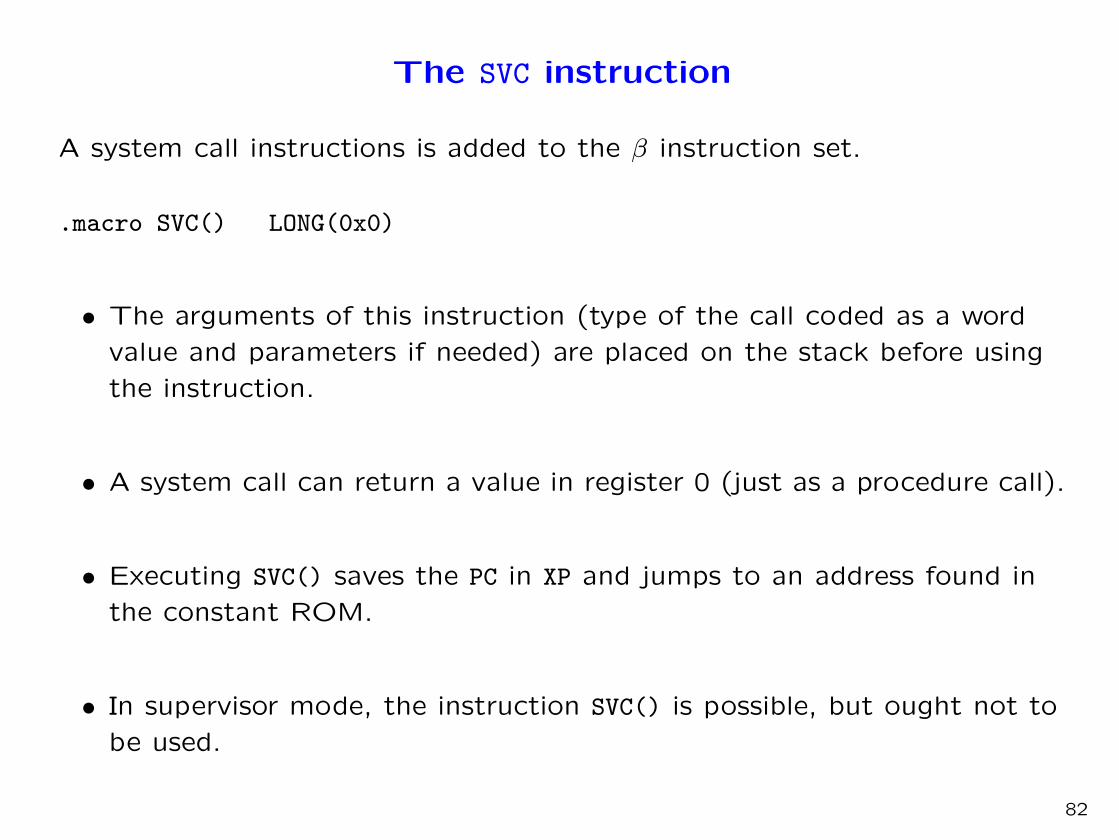
The SVC instruction
A system call instructions is added to the β instruction set.
.macro SVC() LONG(0x0)
• The arguments of this instruction (type of the call coded as a word
value and parameters if needed) are placed on the stack before using
the instruction.
• A system call can return a value in register 0 (just as a procedure call).
• Executing SVC() saves the PC in XP and jumps to an address found in
the constant ROM.
• In supervisor mode, the instruction SVC() is possible, but ought not to
be used.
82
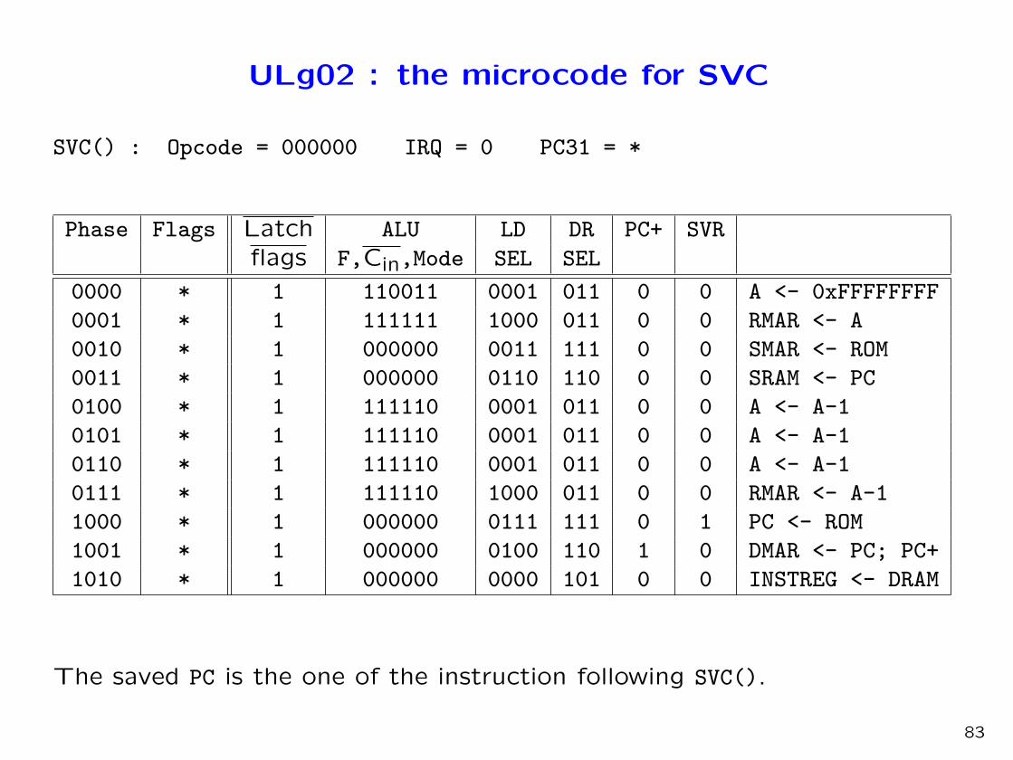
ULg02 : the microcode for SVC
SVC() : Opcode = 000000 IRQ = 0 PC31 = *
Phase Flags Latch ALU LD DR PC+ SVR
flags F,Cin,Mode SEL SEL
0000 * 1 110011 0001 011 0 0 A <- 0xFFFFFFFF
0001 * 1 111111 1000 011 0 0 RMAR <- A
0010 * 1 000000 0011 111 0 0 SMAR <- ROM
0011 * 1 000000 0110 110 0 0 SRAM <- PC
0100 * 1 111110 0001 011 0 0 A <- A-1
0101 * 1 111110 0001 011 0 0 A <- A-1
0110 * 1 111110 0001 011 0 0 A <- A-1
0111 * 1 111110 1000 011 0 0 RMAR <- A-1
1000 * 1 000000 0111 111 0 1 PC <- ROM
1001 * 1 000000 0100 110 1 0 DMAR <- PC; PC+
1010 * 1 000000 0000 101 0 0 INSTREG <- DRAM
The saved PC is the one of the instruction following SVC().
83

The exception handlers
• The exception handlers are the points at which the system is entered
coming from a user program.
• The first thing an exception handler must do is save the state of the
user program.
• The state of the user program is the content of the registers and the
memory it uses. The registers will be saved. The memory being used
must be kept separate from the memory used by the system.
• Later we will describe a technique for keeping the memory used by
user programs and the system completely separate. For the time
being, let us just assume a separate memory area is reserved for each.
84

The exception handler (next)
An exception handler is written in two parts :
• A stub (chicot in French) written in assembly language that saves the
state of the user program.
• The handler itself, which can be written without special care about
registers being used and can thus be written in a high-level language
(very often C).
85

A “stub” for the interrupt handler
The state of the user program is saved in system memory at a fixedaddress: User.
h_stub: SUBC(XP, 4, XP) | prepare to resume with
| the interrupted instruction
ST(r0, User, r31) | save registers
ST(r1, User+4, r31)
. . .
ST(r30, User+30*4, r31)
CMOVE(KStack, SP) | Load the system SP
BR(Handler,LP) | Call the handler
LD(r31, User, r0) | restore
LD(r31, User+4, r1)
LD(r31, User+30*4, r30)
JMP(XP) | return to application
The stub of a system call handler is similar, but SUBC(XP, 4, XP) is notexecuted since XP contains the address of the next instruction to beexecuted.
86

A system handling input/output operations
• Let’s assume ULg02 has a simple input/output interface connected to
a keyboard.
• From a programming point of view, the keyboard interface appears as
two memory addresses: Data and Flag. The address Data contains the
last character typed on the keyboard. The address Flag contains 0 if
no character is available and contains 1 if a character is available.
• If Flag has value 1, the signal IRQ is active.
• We have to write an interrupt handler as well as a handler for the
system call “readkey”.
87

A basic interrupt handler
The program below is the interrupt handler of the system’s kernel.
struct Device { char Flag, Data; } Keyboard;
/* The logical view of the input/output interface */
char Buffer[100];
/*a work area in which the read characters are kept */
int inptr = 0;
/* the next available position */
int outptr = 0;
/* the next character to be read */
IntHandler()
{ Buffer[inptr] = Keyboard.Data;
inptr = (inptr + 1) % 100;
Keyboard.Flag = 0;
}
Thanks to interrupts each character is handled as soon as it is available.
The user program is interrupted, but is not aware of anything.
88

A system call handler
The following handler is executed when the instruction SVC is executed
with the code “keyboard” placed on top of the stack.
struct Mstate { int R0; ..., R30;) User;
/* the saved state of the user program */
KeyHandler()
{ while (ouptr == inptr) {};
User.R0 = Buffer[outptr];
outptr = outptr+1 % 100;
}
89

An improved system call handler
The previous handler gets stuck when called with Buffer empty because it
cannot be interrupted.
If Buffer is empty, one must switch back to the user program and do the
system call again.
KeyHandler()
{ if (ouptr == inptr) {
User.R30 = User.R30 - 4;} /* R30 correspond a XP */
else {
User.R0 = Buffer[outptr];
outptr = outptr+1 % 100;}
}
This program creates a loop that is interrupted when a character becomes
available. To do better, the machine has to be shared between several
user programs.
90

Processes
• While a user program is waiting for an input/output operation, the
machine could be used by other user programs.
• A set of programs being executed or processes thus have to be
managed. Each process has its own reserved memory area and, when
it is not active, the values it has stored in registers are saved.
• The system manages the processes. Each time it has finished what it
has to do, it executes a function scheduler() that chooses the process
that will be activated.
• The information about the processes is kept in a process table.
91
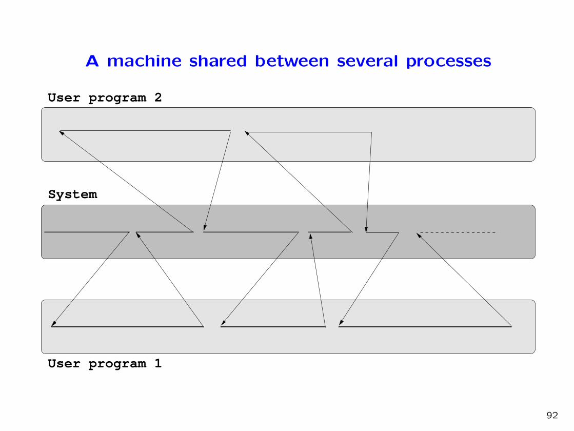
A machine shared between several processes
User program 1
User program 2
System
92
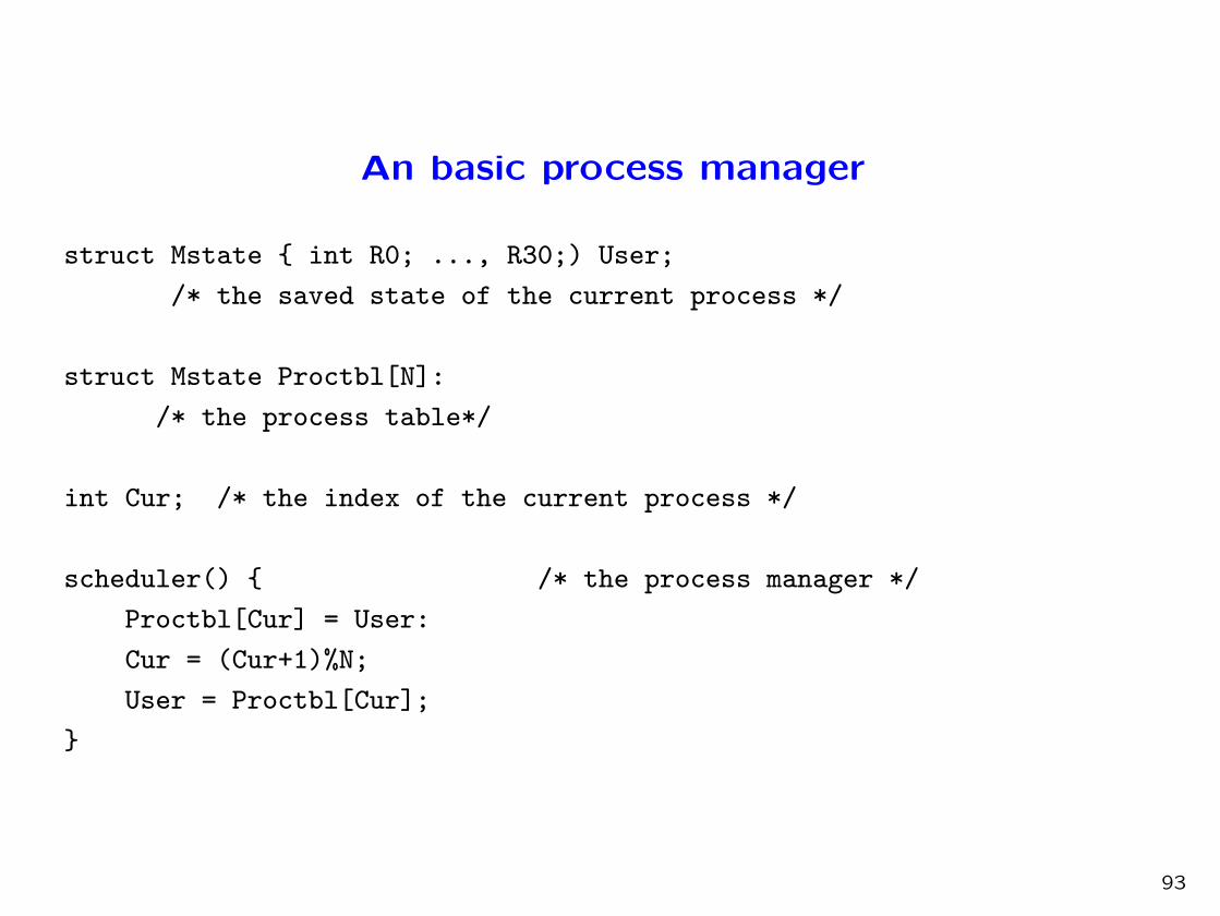
An basic process manager
struct Mstate { int R0; ..., R30;) User;
/* the saved state of the current process */
struct Mstate Proctbl[N]:
/* the process table*/
int Cur; /* the index of the current process */
scheduler() { /* the process manager */
Proctbl[Cur] = User:
Cur = (Cur+1)%N;
User = Proctbl[Cur];
}
93

A system call handler with process management
Now, if Buffer is empty, the process that is resumed will be different from
the one that has executed the system call.
KeyHandler()
{ if (ouptr == inptr) {
User.R30 = User.R30 - 4;
scheduler(); }
else {
User.R0 = Buffer[outptr];
outptr = outptr+1 % 100;}
}
94

Clock interrupts
• Let us assume our machine has a “clock” appearing as a memory
address whose content is incremented at each hardware clock cycle.
• Also assume that this clock generates an interrupt every 10000 clock
cycles.
• The clock interrupt handler could simply be the following one.
ClkintHandler()
{
scheduler();
}
• This guarantees that scheduler is called frequently enough for each
process to be regularly executed.
95

A more elaborate process management
• When a process is waiting for an input/output operation, it is uselessto make it active if the state of the input/output interface has notchanged.
• For this purpose, the process table includes information on the statusof the process, indicating whether the process is active or waiting.When a process is waiting a code indicates what it is waiting for.
• The process table is then defined as follows.
struct PD {struct Mstate state ; int status} Proctbl[N]:
/* the process table with status information */
• With the convention that a 0 status represents an active process anda 1 status a process waiting for a character from the keyboard, we canrewrite our input/output handler.
96

An interrupt handler with process management andstatus information
struct PD {struct Mstate state ; int status} Proctbl[N]:
/* the process table with status information */
IntHandler()
{ int i;
Buffer[inptr] = Keyboard.Data;
inptr = (inptr + 1) % 100;
Keyboard.Flag = 0;
for (i=0;i<=N;i++) {
if (Proctbl.status[i]==1) Proctbl.status[i]=0;}
}
One can obviously avoid cycling through the process table by using
adequate data structures.
97

A system call handler with process management andstatus information
Now, if Buffer is empty, the process waiting for the keyboard is made
inactive.
KeyHandler()
{ if (ouptr == inptr) {
User.R30 = User.R30 - 4;
Proctable.status[Cur] = 1;
scheduler(); }
else {
User.R0 = Buffer[outptr];
outptr = outptr+1 % 100;}
}
It is also necessary to modify scheduler for it not to activate a waiting
process.
98