Embed Size (px)
Citation preview

Towards a WPSL: A Critical Analysis of the 20Classical Workflow Control-flow Patterns
Nataliya Mulyar1, Wil M.P. van der Aalst1,2, Arthur H.M. ter Hofstede2, NickRussell2
1 Department of Technology Management, Eindhoven University of TechnologyGPO Box 513, NL5600 MB Eindhoven, The Netherlands
{n.mulyar, w.m.p.v.d.aalst}@tm.tue.nl2 Faculty of Information Technology, Queensland University of Technology
GPO Box 2434, Brisbane QLD 4001, Australia{a.terhofstede, n.russell}@qut.edu.au
Abstract. In 2000, after a comprehensive survey of tools and techniquesfor workflow management, 20 control-flow patterns were identified [5]and made these available through www.workflowpatterns.com. Since then,many commercial and academic workflow management systems have beenevaluated using these patterns. Moreover, standards such as BPEL andXPDL have been evaluated and these evaluations have triggered improve-ments in them. Although the 20 workflow patterns have proven to beuseful, the selection of these patterns was done in an ad-hoc manner andthe description of the patterns in natural language has been rather am-biguous. Therefore, we propose a more analytical approach using a newWorkflow Pattern Specification Language (WPSL). WPSL is independentof any implementation language utilized by contemporary workflow man-agement systems. In this paper, we analyze the 20 original workflow pat-terns using WPSL, discuss the different variants of the patterns, and useWPSL to capture the detailed semantics of existing workflow managementsystems.
1 Introduction
A multitude of commercial workflow systems is available on the market today.These systems can be characterized by the wide range of unique features andcapabilities of modelling languages they implement. The lack of the appropriatestandards and limited adoptance by commercial vendors of standards proposed bythe Workflow Management Coalition [27, 28] and the Object Management Group[13] explains why comparison of contemporary workflow systems, based on differ-ent concepts and paradigms, is a non-trivial task.
When automating business processes there is often a need to express specificprocess steps using the functionality available in workflow systems. Since the func-tionality of modeling languages employed by workflow systems differs significantly,the selection of an appropriate workflow system is hard to make. This problemhas been addressed in [5, 1, 23, 22, 4] by formulating the requirements for workflowlanguages in form of patterns. The initial set of control-flow patterns has beeninspired by capabilities of WFMS available for analysis. Note however, that the

classical set of the control-flow patterns [5] turned out to be incomplete. This wasno surprise as the original set of patterns was inspired by workflow systems avail-able in the late nineties rather than obtained by systematic analysis. Moreover,current pattern definitions are defined informally and hence can be interpretedin various ways. In this paper, we address this issue using a systematic approachbased on a comprehensive conceptual foundation.
To illustrate different capabilities of the modelling languages adopted by work-flow systems, we briefly review the workflow systems YAWL, COSA, Staffwareand Oracle BPEL PM. We show that even basic constructs such as the XOR-join and AND-join (the Petri-net representations of which are given in Figure 1),which are supported by the majority of workflow systems, are not interpreted ina uniform way.
In Petri-nets, activities are modelled by transitions and causal dependenciesare modelled by places, transitions, and arcs. The XOR-join specifies that severaldistinct paths come together without synchronization (see a place p1 with ingoingarcs from transitions A and B in Figure 1(a)). The AND-join specifies the syn-chronization of multiple paths (see a transition C with incoming arcs from placesp1 and p2 in Figure 1(b)).
p1
A
B
C
A
B
C p2
p1
p2
p3
(a) (b)
Fig. 1. XOR-join and AND-join in Petri Nets
The Petri-net based workflow system YAWL offers a direct support for theXOR-join and AND-join constructs (see Figure 2(a) and (b) respectively). Placesin YAWL have unbounded capacity and to enable a task, each input place mustcontain at least one token to enable a task. In contrast to Petri nets, YAWL alsoallows the modelling of an OR-join (Figure 2(c)), which is a construct that maybehave like an XOR-join or an AND-join (or a mixture of the two) depending onthe context in which it is used. I.e. the OR-join waits untiil no additional tokenscan arrive.
COSA is a Petri-net based workflow management system. The main buildingblocks of COSA are states, activities, and transitions, which are mapped directlyon the concepts of Petri-nets as places, transitions, and arcs respectively. Figure 3depicts the XOR-join and the AND-join on the nets (a) and (b) respectively.COSA can be considered as a safe Petri-net, which is characterized by at mostone token being stored in a place at any given time. Hence, activities block whenthe output states are not empty. For example, activity A blocks when there is a
2

(a) (b) (c)
Fig. 2. Notation of XOR/AND/OR-joins in YAWL
token in place s1. As a result, COSA behaves differently from YAWL and ordinaryPetri nets.
(a) (b)
Fig. 3. Notations of XOR/AND-joins in COSA: activities block if not all output statesare empty
The XOR-join and AND-join constructs in Staffware are denoted by meansof Step and Wait objects (see models (a) and (b) of Figure 4 respectively). TheStep C behaves as an XOR-join, i.e. it is triggered when Step A or Step B hascompleted. Only one instance of C can be active at a time. For instance, if StepC is still active and a new trigger arrived, this trigger will be ignored and allinformation associated with it will be lost. Note that this way a “race condition”is created. Just like COSA, Staffware forces intermediate states to be “safe”.However, COSA enforces safeness by blocking activities, while Staffware simplyremoves excess triggers. The Wait object synchronizes left and top input arcs.This object may have only one left and up to 16 top arcs. However, the Waitobject can be triggered only by a signal arriving at the left arc. When the objecthas been triggered, it starts evaluating the status of the top arcs. When all inputarcs provided input, the Wait object executes. Note that when used in a loop,the Wait object behaves differently. For instance, if Step B is in the loop, butStep A is not, then for the repeated enabling of Step C, it is sufficient for Step
3

B to complete. However, if both steps A and B are in the loop, they both mustcomplete in order to trigger Step C again.
(a) (b)
Fig. 4. Constructs for (a) an XOR-join and (b) an AND-join in Staffware. The defaultsemantics of a step (e.g. C) is an XOR-join. A wait step (sand-timer symbol) needs tobe inserted to synchronize flows (AND-join))
Currently there are many systems supporting BPEL [9]. In this paper, weselected Oracle BPEL as a representative of this class. Oracle BPEL PM imple-ments the XOR-join and the AND-join by means of BPEL activities switch andflow respectively. In contrast to YAWL, Staffware and COSA, these constructsare applied within the structured workflow, i.e. every join is preceded by the cor-responding split-construct. This way the corresponding processes are safe and theexceptional situations mentioned for COSA and Staffware cannot occur.
(a) (b)
Fig. 5. Constructs for an XOR-join and an AND-joins in Oracle BPEL PM. AlthoughBPEL is a textual language, a graphical interface is provided which directly reflects theBPEL code
We showed that implementation of XOR- and AND-joins in COSA, YAWL,Staffware and Oracle BPEL PM differ by the capacity of places, blocking be-havior of activities, etc. Thus, even simple constructs such as the XOR-join andAND-join are not interpreted in a uniform way in different WFM systems. In
4

order to distinguish between the differences identified in the modelling languageswe propose a Workflow Pattern Specification Language (WPSL) that is formallydefined and has a graphical notation that can be used as a means of analyzingand reasoning about the differences in the modelling languages. In addition, weapply WPSL to increase the degree of precision and completeness of the classicalset of the control-flow patterns. Note that the proposed language can be appliedto describe a wide variety of control-flow constructs.
The rest of this paper is organized as follows. Section 2 describes the goal,scope, basic premises and the structure of our WPSL. The syntax and semanticsof WPSL are formally described in Section 2.2. Next, an analysis of the classicalcontrol-flow patterns is done by means of WPSL in Section 3. In Section 4 thepaper concludes with a discussion of the lessons learned. Related work is outlinedin Section 5. Finally, the conclusions and future work are discussed in Section 6.
2 Workflow Pattern Specification Language (WPSL)
In this section we introduce the main concepts of WPSL, followed by the formaldefinition of the language and an example illustrating its applicability.
2.1 Introduction to the language
The graphical Workflow Pattern Specification Language (WPSL) aims to capturethe requirements of Process-Aware Information Systems (PAIS) expressed in theform of patterns. The current specification covers only the control-flow perspectiveand does not consider the data and organizational aspects. The main buildingblock in WPSL is a Task, which is a basic modelling construct encountered inthe process definition language of any Workflow Management System (WFMS).WPSL offers a means for visualizing all kinds of task variants that can be usedfor modelling a business process and provides different ways of combining thesetasks for routing purposes.
The scope of the language is limited to a single case, covering the details of thecase routing, while leaving the external relationships with other cases, processes,and external environments out of consideration.
There are two fundamental premises in regard to the WPSL semantics. Firstof all, all behavior in the modelled process is associated with active tasks, theexecution of which changes the state of the modelled system. Secondly, the mod-elled process behaviors are message-driven and discrete. Discrete means that amodelled system is characterized by a certain state at every moment of time.
WPSL defines fundamental language constructs for representing the control-flow patterns. Figure 6 illustrates the semantics areas of WPSL and the hierar-chical relationship between them.
On the bottom layer, there are three structural language constructs: a task, achannel, and a message. These are the main entities of which a generic workflownet (GWF-net) is composed. In terms of Petri nets, a task, a channel, and amessage correspond to a transition, a place, and a token respectively. A task is an
5
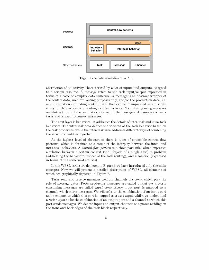
Control-flow patterns
Task Message Channel
Intra-task behavior Inter-task behavior
Case
Patterns
Behavior
Basic constructs
Fig. 6. Schematic semantics of WPSL
abstraction of an activity, characterized by a set of inputs and outputs, assignedto a certain resource. A message refers to the task input/output expressed interms of a basic or complex data structure. A message is an abstract wrapper ofthe control data, used for routing purposes only, and/or the production data, i.e.any information (excluding control data) that can be manipulated as a discreteentity for the purpose of executing a certain activity. Note that by using messageswe abstract from the actual data contained in the messages. A channel connectstasks and is used to convey messages.
The next layer is behavioral; it addresses the details of inter-task and intra-taskbehaviors. The intra-task area defines the variants of the task behavior based onthe task properties, while the inter-task area addresses different ways of combiningthe structural entities together.
At the highest level of abstraction there is a set of extensible control flowpatterns, which is obtained as a result of the interplay between the inter- andintra-task behaviors. A control-flow pattern is a three-part rule, which expressesa relation between a certain context (the lifecycle of a single case), a problem(addressing the behavioral aspect of the task routing), and a solution (expressedin terms of the structural entities).
In the WPSL structure depicted in Figure 6 we have introduced only the mainconcepts. Now we will present a detailed description of WPSL, all elements ofwhich are graphically depicted in Figure 7.
Tasks send and receive messages to/from channels via ports, which play therole of message gates. Ports producing messages are called output ports. Portsconsuming messages are called input ports. Every input port is mapped to achannel, which stores messages. We will refer to the combination of an input portand a channel to which this port is mapped as a task input, whilst we understanda task output to be the combination of an output port and a channel to which thisport sends messages. We denote input and output channels as squares residing onthe front and back edges of the task block respectively.
6

o1
o2
Task Name
i4
i1 c1
i2
Local input port
Local channel (safe)
External input port
External channel (safe)
Output port
jtype blp mcm ism IS OS CS
Optional port
Mandatory port
i5 External channel
(bounded)
Local channel (bounded)
i6 External channel (unbounded)
i3 Local channel (unbounded)
c4
c3
c2
c5
c6
Task attributes:
jtype: join type blp: blocking mode of output ports mcm: message consumption mode ism: input selection mode IS: input sets OS: output sets CS: cancellation set
Fig. 7. The various notations for tasks, channels, and ports
Every GWF-net may have multiple input channels and output channels, how-ever exactly one input channel and one output channels are involved in the initi-ation and termination of the process instance.
Every channel is characterized by a set of parameters, such as the maximalcapacity, the minimal capacity, and the enabling status. The maximal capacityparameter defines how many messages the channel may hold at once. A channelwith unlimited maximal capacity is called an unbounded channel, while a chan-nel with limited maximal capacity is called a bounded channel. We will refer tobounded channels that are able to hold at most one message at a time, as safechannels. We denote safe, bounded and unbounded channels as a single, doubleand triple circles respectively. The direction of the arrows represents the messageflow.
The minimal capacity parameter of a channel defines at least how many mes-sages the channel must contain in order to make a port, consuming messagesfrom this channel, enabled. A channel is enabled if its minimal capacity has beenreached, otherwise the channel is said to be disabled.
Depending on the enabling status of a channel, an input port mapped to it canbe either enabled or disabled. An input port is enabled if the channel to which thisport is mapped is also enabled, otherwise the port is considered to be disabled.
Depending on the level of the visibility of the transferred messages and ac-cessibility to them two types of channels can be distinguished. The local channel(relative to the task input) is used for the dedicated message transfer, i.e. whenmessages sent by a task-producer are to be received by a single dedicated task-consumer, and no other tasks may access the messages stored in this channel. Theexternal channel (relative to the task input) is used for non-dedicated messagetransfer, i.e. when the message sent by a task-producer to the channel is to beconsumed by one of several task-consumers which share access to the messages
7

stored in this channel. To distinguish local and external channels graphically, wemerge local channels with input ports.
Input ports which are mapped to local channels are called local input ports,while input ports mapped to external channels are called external input ports.The availability of messages in input channels is a property associated with inputports. A mandatory input port is a port, which must be enabled before the taskmay commence. An optional input port is a port, the enabling of which is notcompulsory for the task commencement. The output ports can also be mandatoryor optional. An output port produces one message upon task termination. Amandatory output port always produces a message upon task termination. Anoptional output port produces one message upon the task termination if and onlyif a data-based condition associated with this port has been satisfied (we do notelaborate on the data conditions, since in the context of this work we abstractfrom the data perspective). We denote optional and mandatory ports as whiteand dark squares respectively.
Every task has a set of properties that define the input and output logic ofthe task and the behavior of the task in an active state. A task is in the activestate after it has commenced but before it has terminated. The input sets (IS)of a task define all possible sets of input ports, enabling of which is required fortask commencement. The input selection mode (ism) of a task defines which setof enabled input ports is to be selected from the input sets.
The message consumption mode (mcm) of a task defines how many messagesare to be consumed from the channels attached to the ports selected for con-sumption. In minimal message consumption mode, the minimal channel capacityis consumed from each of the channels, attached to the enabled ports selected forthe message consumption. The non-consumed messages remain in the channelsunless these channels are explicitly included in the task cancellation set (CS),which specifies locations from which all messages are to be removed upon tasktermination. In maximal message consumption mode, all messages available in thechannels attached to the enabled ports selected for the message consumption, areconsumed at once.
The output sets (OS) of a task defines a set of output ports each of which willproduce one message at the moment of task termination.
The blocking mode (blp) of output ports is a property defined for each task.In blocked mode, output ports may send messages to the output channels if andonly if the maximal capacity of the corresponding channels has not been reached.If the maximal capacity of the channel has been reached, the output ports areblocked and wait until the required channel capacity becomes available. In openmode, output ports may send messages to the channels the maximal capacity ofwhich has been reached, however these messages will be lost and will not modifythe state of the channels.
The cancellation set (CS) defines which parts of the net should be emptiedat the time of task termination. Emptying part of a GWF-net corresponds toremoving messages from specified locations. Removing messages from a task cor-
8
responds to aborting execution of that task. We denote the cancellation set as adashed-line attached to a task (for an example see an example in Figure 10).
Every task has a data-based guard, the status of which influences the enablingstatus of the task. Furthermore, the join logic of a given task is dependent on thejtype parameter, which specifies whether the processing of the task inputs is local,i.e. based on the messages currently available in the input channels, or future, i.e.postponed until no more new messages may arrive at the task inputs.
2.2 Formal Definition
In this subsection we will formalize the notions just introduced. First, we definea GWF-net.
Definition 1 (GWF-net). A generic workflow net (GWF-net) N is a tuple (C,LC, EC, i, o, T, P, IP, OP, ManP, OptP, ptoc, psend, mincap, maxcap, blp, IS,ism, OS, mcm, CS, guard, jtype, F) where:
• C is a set of channels.
• LC ⊆ C is a set of local channels.
• EC ⊆ C is a set of external channels, such that LC and EC partition C, i.e.LC
⋂EC = ∅ ∧ LC
⋃EC = C.
• i ⊂ C is a set of input channels.
• o ⊂ C is a set of output channels, such that i⋂
o = ∅.
• T is a set of tasks.
• P is a set of ports.
• IP : T → P(P ) defines a set of input ports for each task.
• OP : T → P(P ) defines a set of output ports of a task t ∈ T , such that∀t1,t2∈T : (IP (t1)
⋃OP (t1))
⋂(IP (t2)
⋃OP (t2)) 6= ∅) ⇒ t1 = t2 and IP (t)
⋂OP (t) =
∅ for any task t ∈ T .
• ManP : T → P(P ) defines a set of mandatory ports for each task, such that∀t∈T : ManP (t) ⊆ (IP (t)
⋃OP (t))
• OptP : T → P(P ) defines a set of optional ports for each task, such that∀t∈T : ManP (t)
⋂OptP (t) = ∅ ∧ (ManP (t)
⋃OptP (t) = IP (t)
⋃OP (t))
• ptoc : P → C maps every port to a channel, such that a single input/outputport is mapped to a local channel, while multiple ports can be mapped to thesame external channel.
∀p1,p2∈P∀c∈C : ptoc(p1) = ptoc(p2) = c ⇒ (p1 = p2 ∨ c ∈ EC)
Let p = ptoc(p) for any p ∈ P , and generalize it for sets: X = {ptoc(x)|x ∈X}.
• mincap : C → IN defines the minimal channel capacity. (Note that a channelwith mincap(c)=0 behaves like a reset arc.)
9

• maxcap : C → (IN\{0})⋃{∞} defines the maximal channel capacity.
if maxcap(c) = ∞, then the channel c is unbounded.
if maxcap(c) = k, where k ∈ IN\{0}, then the channel c is bounded.
if maxcap(c) = 1 then the channel c is safe.
• blp : P 9 {blocked, open} defines the blocking mode of all output ports. Notethat dom(blp) =
⋃t∈T OP (t).
• IS : T → P(P(P )) defines input sets for each task, specifying input ports theenabling of which is sufficient for the task commencement, such that(∀t∈T∀Q∈IS(t) : (Q ⊆ IP (t) ∧ (ManP (t)
⋂IP (t) ⊆ Q)))
• ism : T → {max,min, ran} defines the input selection mode of a task.
max: select a ”maximal” set of IS(t), i.e. there is no a larger set Q of enabledinput ports in IS(t) with respect to set inclusion.
min: select a ”minimal” set of IS(t), i.e. there is no a smaller set Q ofenabled input ports in IS(t) with respect to set inclusion.
ran: select any set of enabled input ports in IS(t).
• OS : T → P(P(P )) defines output sets of a task specifying what output portsare to produce messages upon the task termination, such that(∀t∈T∀Q∈OS(t) : (Q ⊆ OP (t) ∧ (ManP (t)
⋂OP (t) ⊆ Q)))
• mcm : T → {min,max} defines the message consumption mode, i.e. howmany messages are to be consumed from the enabled inputs selected accordingto ism(t) for the given task t ∈ T .
min: consume the number of messages specified by the minimal capacity pa-rameter of the channel.
max: consume all messages available in the channel.
• CS : T → P((C⋃
T ) \ {i, o}) specifies the task cancellation set, i.e. whatadditional messages are to be removed by emptying a part of the workflow.
• guard : T → Bool defines the status of the data-based task guard, which influ-ences the enabling status of the task. (Note that the signature of this functionmight be misleading, since the dependency on data elements is missing dueto the abstraction from the data perspective. Given a task t, guard(t) mayevaluate to true or false depending on the data values at the moment ofevaluation.)
• jtype : T → {local, future} specifies whether the processing of the task inputsis local, i.e. based on the messages currently available in the input channels,or future, i.e. postponed until no more new messages may arrive at the taskinputs.
• F = {(c, t) ∈ C×T |c ∈ IP (t)⋃{(t, c) ∈ T ×C|c ∈ OP (t)} is the flow relation.
• every node in the graph (C⋃
T, F ) is on the directed path from some c1 ∈ ito some c2 ∈ o, i.e.
10
(∀x∈C�
T∃c1∈i∃c2∈o : (c1, x) ∈ F ∗ ∧ (x, c2) ∈ F ∗)
where F ∗ is the transitive closure of F .
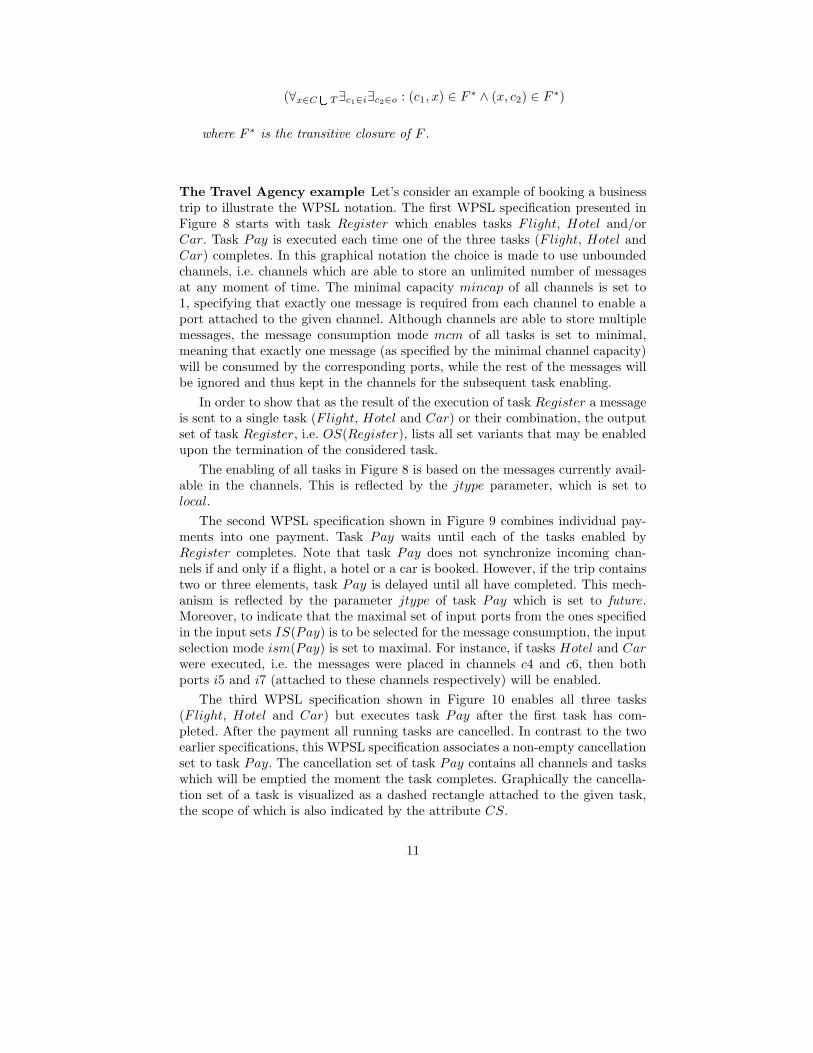
The Travel Agency example Let’s consider an example of booking a businesstrip to illustrate the WPSL notation. The first WPSL specification presented inFigure 8 starts with task Register which enables tasks Flight, Hotel and/orCar. Task Pay is executed each time one of the three tasks (Flight, Hotel andCar) completes. In this graphical notation the choice is made to use unboundedchannels, i.e. channels which are able to store an unlimited number of messagesat any moment of time. The minimal capacity mincap of all channels is set to1, specifying that exactly one message is required from each channel to enable aport attached to the given channel. Although channels are able to store multiplemessages, the message consumption mode mcm of all tasks is set to minimal,meaning that exactly one message (as specified by the minimal channel capacity)will be consumed by the corresponding ports, while the rest of the messages willbe ignored and thus kept in the channels for the subsequent task enabling.
In order to show that as the result of the execution of task Register a messageis sent to a single task (Flight, Hotel and Car) or their combination, the outputset of task Register, i.e. OS(Register), lists all set variants that may be enabledupon the termination of the considered task.
The enabling of all tasks in Figure 8 is based on the messages currently avail-able in the channels. This is reflected by the jtype parameter, which is set tolocal.
The second WPSL specification shown in Figure 9 combines individual pay-ments into one payment. Task Pay waits until each of the tasks enabled byRegister completes. Note that task Pay does not synchronize incoming chan-nels if and only if a flight, a hotel or a car is booked. However, if the trip containstwo or three elements, task Pay is delayed until all have completed. This mech-anism is reflected by the parameter jtype of task Pay which is set to future.Moreover, to indicate that the maximal set of input ports from the ones specifiedin the input sets IS(Pay) is to be selected for the message consumption, the inputselection mode ism(Pay) is set to maximal. For instance, if tasks Hotel and Carwere executed, i.e. the messages were placed in channels c4 and c6, then bothports i5 and i7 (attached to these channels respectively) will be enabled.
The third WPSL specification shown in Figure 10 enables all three tasks(Flight, Hotel and Car) but executes task Pay after the first task has com-pleted. After the payment all running tasks are cancelled. In contrast to the twoearlier specifications, this WPSL specification associates a non-empty cancellationset to task Pay. The cancellation set of task Pay contains all channels and taskswhich will be emptied the moment the task completes. Graphically the cancella-tion set of a task is visualized as a dashed rectangle attached to the given task,the scope of which is also indicated by the attribute CS.
11

s1 c4 e1
Register
jtype blp mcm ism IS OS CS
i1
o1
o2
o3
Hotel
jtype blp mcm ism IS OS CS
i3 o5
Flight
jtype blp mcm ism IS OS CS
i2 o4
Car
jtype blp mcm ism IS OS CS
i4 o6
Pay
jtype blp mcm ism IS OS CS
i5 o7
c1
c2
c3
jtype(Register)=local jtype(Pay)=local mincap(s1)=1 mcm(Register)=min mcm(Pay)=min mincap(c1)=1 ism(Register)=min ism(Pay)=min mincap(c2)=1 IS(Register)={{i1}} IS(Pay)={{i5}} mincap(c3)=1 OS(Register)={{o1},{o2},{o3},{o1,o2},{o2,o3},{o1,o3},{o1,o2,o3}} OS(Pay)={{o7}} mincap(c4)=1 CS(Register)={} CS(Pay)={} mincap(e1)=1
jtype(Flight)=local jtype(Hotel)=local jtype(Car)=local mcm(Flight)=min mcm(Hotel)=min mcm(Car)=min ism(Flight)=min ism(Hotel)=min ism(Car)=min IS(Flight)={{i2}} IS(Hotel)={{i3}} IS(Car)={{i4}} OS(Flight)={{o4}} OS(Hotel)={{o5}} OS(Car)={{o6}} CS(Flight)={} CS(Hotel)={} CS(Car)={}
for all output ports p: blp(p)=open
Fig. 8. Task Pay executes each time one of the three preceding tasks completes
12

s1 e1
Register
jtype blp mcm ism IS OS CS
i1
o1
o2
o3
Hotel
jtype blp mcm ism IS OS CS
i3 o5
Flight
jtype blp mcm ism IS OS CS
i2 o4
Car
jtype blp mcm ism IS OS CS
i4 o6
Pay
jtype blp mcm ism IS OS CS
i5
o7
c1
c2
c3
jtype(Register)=local jtype(Pay)=future mcm(Register)=min mcm(Pay)=min ism(Register)=min ism(Pay)=max IS(Register)={{i1}} IS(Pay)={{i5},{i6},{i7},{i5,i6}, {i5,i7}, {i6,i7},{i5,i6,i7}} OS(Register)={{o1},{o2},{o3},{o1,o2},{o2,o3},{o1,o3}, {o1,o2,o3}} OS(Pay)={{o7}} CS(Register)={} CS(Pay)={}
jtype(Flight)=local jtype(Hotel)=local jtype(Car)=local mincap(s1)=1 mcm(Flight)=min mcm(Hotel)=min mcm(Car)=min mincap(c1)=1 ism(Flight)=min ism(Hotel)=min ism(Car)=min mincap(c2)=1 IS(Flight)={{i2}} IS(Hotel)={{i3}} IS(Car)={{i4}} mincap(c3)=1 OS(Flight)={{o4}} OS(Hotel)={{o5}} OS(Car)={{o6}} mincap(c4)=1 CS(Flight)={} CS(Hotel)={} CS(Car)={} mincap(c5)=1
mincap(c6)=1 for all output ports p: blp(p)=open mincap(e1)=1
c4
i6 c5
i7 c6
Fig. 9. Task Pay executes only once, i.e. after all started tasks have completed
13

s1 c4 e1
Register
jtype blp mcm ism IS OS CS
i1
o1
o2
o3
Hotel
jtype blp mcm ism IS OS CS
i3 o5
Flight
jtype blp mcm ism IS OS CS
i2 o4
Car
jtype blp mcm ism IS OS CS
i4 o6
Pay
jtype blp mcm ism IS OS CS
i5 o7
c1
c2
c3
jtype(Register)=local jtype(Pay)=local mcm(Register)=min mcm(Pay)=min ism(Register)=min ism(Pay)=min IS(Register)={{i1}} IS(Pay)={{i5}} OS(Register)={{o1},{o2},{o3},{o1,o2},{o2,o3},{o1,o3}, {o1,o2,o3}} OS(Pay)={{o7}} CS(Register)={} CS(Pay)={c1,c2,c3,c4, Flight, Hotel, Car}
jtype(Flight)=local jtype(Hotel)=local jtype(Car)=local mincap(s1)=1 mcm(Flight)=min mcm(Hotel)=min mcm(Car)=min mincap(c1)=1 ism(Flight)=min ism(Hotel)=min ism(Car)=min mincap(c2)=1 IS(Flight)={{i2}} IS(Hotel)={{i3}} IS(Car)={{i4}} mincap(c3)=1 OS(Flight)={{o4}} OS(Hotel)={{o5}} OS(Car)={{o6}} mincap(c4)=1 CS(Flight)={} CS(Hotel)={} CS(Car)={} mincap(e1)=1
for all output ports p: blp(p)=open
CS(Pay)
Fig. 10. Task Pay executes only once, i.e. after the first task has completed
14

2.3 Semantics
Definition 1 specifies the syntax of the GWF-net in mathematical terms, howeverit does not give any semantics. For this purpose, we define state space and statetransitions.
The state space of GWN-net consists of a collection of messages, which serveas wrappers for data 1. In order to deal with identical messages which may accu-mulate in channels we use bags also known as multi-sets. The state of a channelis represented by a multi-set of messages. In order to define the state space, wefirst introduce some notations.
Notation Let’s denote input ports and output ports of a task t ∈ T as •t andt•, and input channels and output channels of the task as •t and t• respectively,such that:
•t = IP (t)t• = OP (t)•t = •tt• = t•
A bag over alphabet A is a function from A to the natural numbers IN. For somebag X over alphabet A and a ∈ A, X(a) denotes the number of occurrences of a inX, and is referred to as the cardinality of a in X. [] denotes the empty bag, [a, a, b]and [a2, b] denote the bag containing two a’s and one b. Let B(A) denote the setof all bags over A. The sum of two bags X and Y , denoted X
⊎Y , is defined as
[an|a ∈ A ∧ n = X(a) + Y (a)]. The difference of X and Y , denoted as X − Y , isdefined as [an|a ∈ A∧n = max((X(a)−Y (a)), 0)]. The size of the bag is denotedas size(X) =
∑a∈A X(a). The restriction of X to some domain D ⊆ A, denoted
as X � D, is defined as [aX(a)|a ∈ D]. Restriction binds more strongly than sumand difference (note that the binding of sum and difference is left-associative). BagX is a sub-bag of Y , denoted as X ⊆ Y , iff for all a ∈ A,X(a) ≤ Y (a). X ⊂ Yiff X ⊆ Y and for some a ∈ A,X(a) < Y (a). Note that any finite set of elementsfrom A also denotes a unique bag over A, namely the function yielding 1 for everyelement in the set and 0 otherwise. Therefore, finite sets can be also used as bags.If X is a bag over A and Y is a finite subset of A, then X−Y,X
⊎Y, Y −X,Y
⊎X
yield bags over A. Let set(x) denote a function which transforms a bag x ∈ B(A)into a set, such that set(x) = {a ∈ A|x(a) ≥ 1}.
State space
Definition 2 (State space). Let N=(C, LC, EC, i, o, T, P, IP, OP, ManP,OptP, ptoc, psend, mincap, maxcap, blp, IS, ism, OS, mcm, CS, guard, jtype, F)be a GWF-net. A workflow state s is a multi-set over the channels and tasks, i.e.s ∈ S, where S = B(C
⋃T ) is the state space of N .
1 Note that in this specification we do not consider the data perspective.
15

Whenever there is a need to refer to a set of locations (i.e. either channelsor internal task states) marked in state s by messages, we will use the functionset(s) = {x ∈ C
⋃T |x ∈ s}.
Let’s consider the task lifecycle visualized in Figure 11. This figure shows theinternal structure of a task t. Note that in a state s ∈ S, there is a token in Activet
if and only if t ∈ S. A task is considered to be active if its internal state is markedby a message, i.e. after the task has commenced but before it has terminated.
Active_t
Task_t
Enter_t Exit_t
Fig. 11. The internal task states
Definition 3 (Task enabling). Let N=(C, LC, EC, i, o, T, P, IP, OP, ManP,OptP, ptoc, psend, mincap, maxcap, blp, IS, ism, OS, mcm, CS, guard, jtype, F)be a GWF-net. The boolean function enable(t, s) evaluates to true if and only iffor a task t ∈ T in state s ∈ S the following set of conditions is satisfied:
– The task guard is satisfied:
guard(t) = true
– One of the input sets is enabled:
(∃Q∈IS(t) : Q ⊆ {p ∈ •t|s(p) ≥ mincap(p)})
– Let S′ be a set of states reachable from s (assuming some reachability relation).If jtype(t) = future, then 6 ∃s′∈S′s� (•t) ⊂ s′� (•t).
Let’s clarify the semantics of the message consumption/production using a taskwith multiple input and output ports connected to single external input andoutput channel respectively. This situation is depicted in Figure 12.To illustrate the semantics, we consider two cases:
• If IS(Task1) = {{i1}, {i2}} and OS(Task1) = {{o1}, {o2}}, then a singlemessage is consumed from the channel c1 and a single message is producedto channel c2.
• However, if IS(Task1) = {{i1, i2}} and OS(Task1) = {{o1, o2}}, then thereis an asymmetry in the message consumption/production, i.e. a single message
16

Task 1
i1 jtype blp mcm ism IS OS
o1
i2 o2
c1 c2
Fig. 12. Message consumption/production
is consumed from channel c1 and two messages are produced to channel c2.Note that such an asymmetry has to do with rules for task enabling, messageconsumption and message production. If the minimal capacity of the channelc1 has been reached, both input ports i1 and i2 of Task 1 become enabled. At atime of the task activation, the minimal capacity of the channel c1 is consumedonce by input ports (either i1 or i2), while upon the task termination bothoutput ports produce a message to the outgoing channel c2.
Enabling of a task t with jtype(t) = future and multiple inputs which need to besynchronized (we will refer to such tasks as OR − joins) needs to be postponeduntil no more messages can arrive resulting in enabling of a larger number ofinput ports of the OR-join. Since enabling of the OR-join depends on the possiblefuture states, its semantics is non-local. Non-locality of the semantics of the OR-join has been a subject for a debate, and as a consequence several approachesto handle non-locality semantics have been proposed. In [2] Kindler, Desel andvan der Aalst address the problem of non-local semantics in the context of EPCsdemonstrating that there is no sound formal semantics for EPCs that is fullycompliant with the informal semantics of EPCs. In [15, 16] Kindler defines a non-local semantics of EPCs using techniques from fixed point theory and a pair oftwo corresponding transition relations. The proposed technique is claimed to beapplicable for formalizing all kinds of non-local semantics. In [29] Wynn, Edmond,van der Aalst and ter Hofstede propose a general and formal approach to OR-joins in workflow using Reset-nets. The authors examine the concept of the OR-join in the context of the workflow language YAWL and propose an algorithmicapproach towards determining OR-join enablement. Because the issue of non-localsemantics of OR-joins is a subject for an investigation on its own, we considerthis issue to be outside of the scope of this work. Thus, we assume that a suitableapproach for dealing with non-local semantics of OR-joins is known. Therefore,we assume some S′ in Definition 3, i.e. S′ is the set of reachable states and ifjtype(t) = future, then the enabling of t depends on this set S ′.
State transitions Let’s formalize the transitions possible in a given state bymeans of binding functions bindingenter and bindingexit corresponding to thetask commencement, which brings a task from the disabled state to the activestate, and the task termination, which brings a task from an active state back tothe disabled state, respectively.
17

Definition 4. Let N=(C, LC, EC, i, o, T, P, IP, OP, ManP, OptP, ptoc, psend,mincap, maxcap, blp, IS, ism, OS, mcm, CS, guard, jtype, F) be a GWF-net. Theboolean function bindingenter(t, cons, prod, s) evaluates to true if and only if thetransition enter can occur for a task t ∈ T in the state s ∈ S, while consuming thebag of messages cons and producing the bag of messages prod, and the followingconditions are satisfied:
– The task t is enabled in the given state s:
enable(t, s) = true
– Messages to be consumed are present in the state:
cons ⊆ s
– There exists a set Q ∈ IS(t) such that:
• Messages are consumed from inputs of the task:
set(cons) = Q
• If the input selection mode is set to maximal, then a maximal set of enabledinput ports of IS(t) is selected, i.e. there is no a bigger set with respect toset inclusion:
if ism(t) = max, then∀Q′∈IS(t)(Q ⊆ Q′) ⇒ ∃p∈Q′\Qs(p) < mincap(p)
• If the input selection mode is set to minimal, then a minimal set of enabledtask inputs of IS(t) is selected for the message consumption, i.e. there isno a smaller set with respect to the set inclusion:
if ism(t) = min, then (∀Q′∈IS(t) : Q′ 6⊂ Q)
• If the input selection mode is set to random, then any set of enabled taskinputs of IS(t) can be selected for the message consumption.
– One message is created for the active task state:
prod = [t]
– The task is not active yet:
t /∈ s
– The number of messages consumed from the selected task inputs is determinedby the message consumption mode of the considered task. In the minimal mes-sage consumption mode, the number of messages required for enabling of theinput is consumed, while the rest of the messages remain in the input chan-nels. In the maximal message consumption mode all messages contained inthe channels of the selected input ports are consumed. For all c ∈ set(cons):
(mcm(t) = min) ⇒ (cons(c) = mincap(c))
(mcm(t) = max ) ⇒ (cons(c) = s(c))
18

Definition 5. The boolean function bindingexit(t, cons, prod, s) evaluates to trueif and only if the transition exit can occur for a task t in state s, while consumingthe bag of messages cons and producing the bag of messages prod, and the follow-ing conditions are satisfied:
– Task t is active in state s:
t ∈ s
– One message is consumed from the internal task state:
cons = [t]
– There exists a set Q ∈ OS(t) such that potentially one message is produced foreach of the selected output ports and the maximal channel capacity is respected(cf. blocking mode):
prod′ = [p1|p ∈ Q]
if blp(t) = blocked, then prod = prod′ and ∀c∈t•(s⊎
prod)(c) ≤ maxcap(c)
if blp(t) = open, then ∀c∈t•prod(c) = min(prod′(c), (maxcap(c) − s(c)))
Definition 6. The boolean function bindingCSexit(t, cons, prod, s) yields true if and
only if there exists a cons′ such that bindingexit(t, cons′, prod, s) yields true andfor any x ∈ C
⋃T :
cons(x) = (s − cons′)⋃
prod(x) if x ∈ CS(t)
cons(x) = cons′(x) if x /∈ CS(t)
I.e., messages are removed from all input channels of task t and from its cancella-tion set. This implies cancellation of tasks in the cancellation set which have notyet completed.
Definition 7. Let N=(C, LC, EC, i, o, T, P, IP, OP, ManP, OptP, ptoc, psend,mincap, maxcap, blp, IS, ism, OS, mcm, CS, guard, jtype, F) be a GWF-net. TheBoolean function binding(t, cons, prod, s) yields true if and only if any of thefollowing conditions holds:
- The enter part of a task is enabled:
bindingenter(t, cons, prod, s)
- The exit part of a task is enabled:
bindingCSexit(t, cons, prod, s)
Definition 8. Let N=(C, LC, EC, i, o, T, P, IP, OP, ManP, OptP, ptoc, psend,mincap, maxcap, blp, IS, ism, OS, mcm, CS, guard, jtype, F) be a GWF-net, ands1 and s2 two workflow states of S. s1 � s2 if and only if there are t ∈ T ,cons, prod ∈ S such that binding(t, cons, prod, s1) and s2 = (s1 − cons) ] prod.
19
� defines a transition relation on the states of the given workflow. The re-flexive transitive closure of � is denoted �∗ and R(s) = {s′ ∈ S|s �∗ s′} is theset of states reachable from state s.
The state space S and transition relation � define a transition system (S,�)for a given GWF-net. This completes the formalization of GWF-nets. Using thisformalization we can also reason about the correctness of GWF-nets. For example,we can generalize the well-known soundness property as shown in Definition 9.
Definition 9 (Soundness). Let N=(C, LC, EC, i, o, T, P, IP, OP, ManP,OptP, ptoc, psend, mincap, maxcap, blp, IS, ism, OS, mcm, CS, guard, jtype, F)be a GWF-net.
- N has the option to complete iff for any state s ∈⋃
c∈i R([c]) : ∃c∈o[c] ∈ R(s).
- N has no dead tasks iff for any t ∈ T there is a state s ∈⋃
c∈i R([c]) suchthat t ∈ set(s).
- N has proper completion iff for any state s ∈⋃
c1∈i R([c1]): ∀c2 ∈ o : (s ≥ [c2])⇒(s = [c2]).
N is sound iff N has the option to complete, has no dead tasks, and has propercompletion.
Note that three GWF-nets used in the Travel Agency example have optionto complete and have no dead tasks. In contrast to the GWF-nets depicted inFigures 9 and 10, the GWF-net in Figure 8 has no proper completion because ofmultiple messages produced by task Pay to the end channel e1.
We could also formally define multiple instances of a task as it has been donein [3], however we chose not complicate things any further. In the next section,we consider control-flow patterns involving multiple instances of a task and forthis we only introduce a graphical notation while abstracting from the formaldefinition.
3 Analysis of the classical Workflow Control Patterns
In this section, we analyze the classical set of control-flow patterns using thenotation of WPSL. Each pattern can be addressed in several ways, dependingon the context in which the given pattern is applied. Therefore, we offer thedefault WPSL notation, which captures the essence of the pattern; then we listvariation points to illustrate alternative configurations of the considered pattern.Furthermore, for each pattern we show the precise notation adopted by Staffwareand Oracle BPEL PM, and how those can be mapped to WPSL.The list of variation points is shown below:
• Channel characteristics: the channel capacity defines how many messagesthe channel may store at once; the channel positioning specifies whether alocal or external type of a channel can be used for the message transfer.
• Blocking of output ports: specifies whether output ports may producemessages in the open or blocked mode.
20
• Message consumption mode: defines whether all messages available inthe channel are consumed at once (the maximal mode) or only the minimalchannel capacity is consumed while leaving the rest of the messages in thechannel (the minimal mode).
• Input selection mode: specifies whether the minimal, maximal or randomset of enabled input ports from the perspective of the set inclusion can beselected for the message consumption.
• Input sets: specifies the logic over the input ports enabling of which is suf-ficient for task enabling.
• Output sets: specifies the logic over the output ports which will producemessages at a time of the task termination.
• Cancellation set: specifies tasks and channels from which messages must beremoved at the time of the task termination.
3.1 WP1 -Sequence
Description An activity in a workflow process is enabled after the completionof another activity in the same process. 2
Selected WPSL specification Figure 13 shows the Sequence pattern. In termsof WPSL task t2 is executed after the execution of task t1. Messages aretransferred via a safe external channel c1. The blocking mode of an outputport o1 of task t1 is chosen to be open to allow task t1 to complete if thechannel c1 is non-empty. The enabling of task t2 is based on the messagescurrently available in the channel, i.e. jtype is set to local. The messagesare consumed in the minimal message consumption mode. The choice of theinput selection mode for this net is irrelevant, since the number of the inputports is limited to one, thus no option for the input selection is available.However, to make the specification complete, ism of t2 is set to minimal. Forthe sake of convenience input sets of task t1 and output sets of task t2 whichmay vary without influencing the behavior of a pattern are omitted in thisnet and in other nets considered further in this paper. This is one of manypossible interpretations of the pattern.
Alternative WPSL specifications The variation points based on which alter-native configurations of the Sequence pattern can be based are listed below:
• Channel characteristics. Channel capacity : the maximal channel ca-pacity can be increased from safe to bounded or unbounded, dependingon the number of messages the channel is able to store at once. If theminimal channel capacity mincap(c1) = 1 does not change, this notationis equivalent to the main notation. Note however, that by increasing theminimal channel capacity, the enabling of the input port connected to this
2 The term ‘activity’ used in [5], from which the pattern definition is cited, should beinterpreted as ‘task’. We omit repeating this remark for the rest of the patterns, thusassuming that terms ‘task’ and ‘activity’ can be used interchangeably.
21

o1
Task 1
jtype blp mcm ism IS OS CS
Task 2
i1 jtype blp mcm ism IS OS CS
blp(o1) = open OS(t1)={{o1}} CS(t1)={}
jtype(t2)= local mcm(t2)= min ism(t2)=min IS(t2)={{i1}} CS(t2)={}
c1
Channel c1 is safe, i.e. maxcap(c1)=1 mincap(c1)=1
Fig. 13. WP1 - Sequence. Selected WPSL specification.
channel would be delayed until the specified minimal channel capacity isreached.Channel positioning : external channel can be used with an additional re-quirement that no other tasks than the dedicated one are connected tothis channel. However, for dedicated message transfer, the local channeltype can be selected.
• Blocking of output ports. Output port o1 of task t1 can be set as openor blocked. If the safe channel c1 is not empty, the open output port o1 oftask t1 is allowed to produce a message, however this message will be lost.If the output port is in the blocked mode, the completion of task t1 willbe postponed until the capacity of the channel c1 is freed. Note that ifthe maximal capacity of the channel c1 is unbounded, the output port o1of task t1 is always open and is never blocked since the maximal capacityof the channel cannot be reached.
• Message consumption mode. In the minimal message consumptionmode the number of messages required to enable the channel (equivalent tothe minimal channel capacity) is consumed, the rest of the non-consumedmessages are stored in the channel for the subsequent task execution. Toconsume all messages available in the channel, the message consumptionmode should be set to maximal.
Note that the initial pattern definition in [5] does not specify such attributes asthe message consumption mode, the blocking of output ports, and the channelcapacity, which makes the pattern subject to multiple interpretations.
Staffware implementation The Staffware model of the Sequence and its cor-responding WPSL interpretation are presented in Figure 14 (a) and (b) re-spectively. The behavior of this pattern can be described by means of theWPSL attributes as follows. Messages in Staffware are transferred via a safechannel (c1 is chosen to be safe, i.e. maxcap(c1) = 1). The enabling of task Bis based on the messages available locally (jtype(B) = local). The consump-
22

tion of messages is performed in the minimal message consumption mode(mcm(B) = min). In Staffware messages can be sent to a channel even if thecapacity of the channel has been reached. The second message will cancel thefirst one. Although Staffware has no notion of ports, the described behaviorcorresponds to the open mode of the output port (blp(o1) = open) in theWPSL terms.
o1
A
jtype blp mcm ism IS OS CS
B
i1 jtype blp mcm ism IS OS CS
CS(A)={} jtype(B)= local mincap(c1)=1 OS(A)= {{o1}} mcm(B)= min maxcap(c1)=1 blp(o1) = open CS(B)= {}
IS(B)= {{i1}}
c1
a) b)
Fig. 14. Staffware implementation of WP1.
Oracle BPEL PM implementation The 〈sequence〉 construct presented inFigure 15, which also corresponds to the BPEL code listed below, allowsthe definition of the collection of tasks to be performed in lexical order.
o1
A
jtype blp mcm ism IS OS CS
B
i1 jtype blp mcm ism IS OS CS
OS(A)= {{o1}} jtype(B)= local mincap(c1)=1 CS(A)={} IS(B)= {{i1}} maxcap(c1)=1
mcm(B)= min ism(B)=min CS(B)= {}
c1
a) b)
Fig. 15. Oracle implementation of WP1.
<sequence name="Sequence_1">
<empty name="A"/>
23

<empty name="B"/>
</sequence>
We will omit pieces of the XML-code further in this document, since theyget larger for more complex patterns, and OracleBPEL diagrams adequatelyreflect the structure of the BPEL code.
The fact that BPEL is structured and acyclic, implies that it does not facilitatereasoning about attributes such as the input selection mode and the blockingmode of the ports. Activity B is enabled as soon at it is triggered by a message,therefore jtype of the corresponding WPSL task is set to local. It is sufficient tohave a single trigger for enabling of a task, therefore the message consumptionmode of task B is set to minimal.
3.2 WP2 -Parallel Split
Description A point in the workflow process where a single thread of controlsplits into multiple threads of control which can be executed in parallel, thusallowing activities to be executed simultaneously or in any order.
Selected WPSL specification Figure 16 shows the Parallel Split pattern.
o1
Task t1
jtype blp mcm ism IS OS CS
Task t2
i1 c1 jtype blp mcm ism IS OS CS
Task t3
i2 c2 jtype blp mcm ism IS OS CS
o2
OS(t1)={{o1,o2}} CS(t1)={}
jtype(t2)= local mcm(t2)= min ism(t2)=min IS(t2)={{i1}} CS(t2)={}
jtype(t3)= local mcm(t3)= min ism(t3)=min IS(t3)={{i2}} CS(t3)={}
for all output ports p: blp(p)=blocked
mincap(c1)=1 maxcap(c1)=1 mincap(c2)=1 maxcap(c2)=1
Fig. 16. WP2 - Parallel Split. Selected WPSL specification.
The execution of task t1 enables execution of tasks t2 and t3. As a result ofthe execution of task t1 messages must be produced for two outgoing channelsc1 and c2, therefore ports o1 and o2 are denoted as mandatory (see the outputset of task t1). Since tasks t2 and t3 are independent of each other, messagesto them are sent via dedicated channels. The enabling of tasks t2 and t3 isbased on the local availability of the messages in channels c1 and c2, whichare chosen to be safe.
24

Alternative WPSL specifications The variation points based on which alter-native configurations of the Parallel Split pattern can be based are listedbelow.
• Channel characteristics. Channel capacity : the capacity of channels c1and c2 can be bounded or unbounded depending on the number of mes-sages the channel is allowed to store at once. To specify that multiplemessages are required to enable an input port(s) of a certain task, theminimal capacity of the corresponding non-safe channels must be set re-spectively.Channel positioning : instead of local channels, external channels can beused with an additional requirement that access to the messages storedin the channel is limited to a single dedicated task.
• Blocking of output ports. Depending on the type of channels used,output ports can be set to blocked or open mode. Setting the blockedmode for the ports producing messages to unbounded channels does notmake sense, since the capacity of the channel will never be reached andan output port will never be blocked. However, both modes are applicablein the context of safe and bounded channels.
• Input selection mode. Since the core logic of the Parallel Split patternis defined in the task t1, the setting of ism is less relevant for this task.Tasks t2 and t3 have a single input port, and there is no option for inputselection. All modes for input selection are equivalent when applied toa task with a single input port. In the remainder of this paper, we willavoid further discussion on input selection mode for tasks with single inputports. However, to make the specification complete, the input selectionmode for such tasks will be set to minimal.
• Message consumption mode. In minimal message consumption mode,the number of messages required to enable the channel (equivalent to theminimal channel capacity) is consumed, the rest of the non-consumedmessages are stored in the channel for the subsequent task execution. Toconsume all messages available in the channel, the message consumptionmode should be set to maximal.
Note that the original pattern definition in [5] does not specify the blockingmode of the output ports or any of the other issues mentioned above.
Staffware implementation Staffware supports the Parallel Split pattern di-rectly as illustrated in Figure 17 (a) by means of a Step object with multipleoutgoing arcs. Figure 17 (b) depicts the corresponding WPSL interpretation.Similar to the description of the Sequence pattern, task A corresponding toStep A is characterized by the open mode of the output ports, enabling basedon the local message availability and the minimal message consumption mode.The split logic of Step A, which propagates a message to Steps B and C, isincorporated into the output set of the WPSL task A.
25
o1
A
jtype blp mcm ism IS OS CS
B
i1 c1 jtype blp mcm ism IS OS CS
C
i2 c2 jtype blp mcm ism IS OS CS
o2
OS(A)={{o1,o2}} CS(A)={}
jtype(B)= local mcm(B)= min ism(B)=min IS(B)={{i1}} CS(B)={}
jtype(C)= local mcm(C)= min ism(C)=min IS(C)={{i2}} CS(C) ={}
for all output ports p: blp(p)=open
mincap(c1)=1 maxcap(c1)=1 mincap(c2)=1 maxcap(c2)=1
a) b)
Fig. 17. Staffware implementation of WP2.
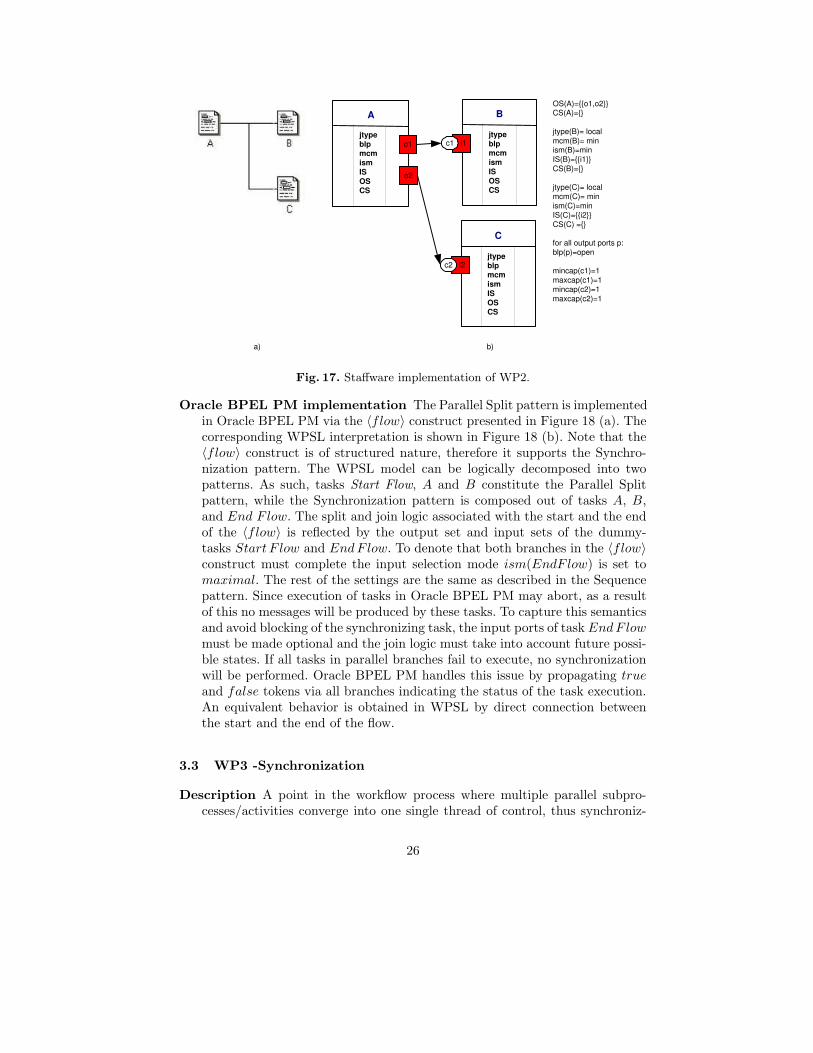
Oracle BPEL PM implementation The Parallel Split pattern is implementedin Oracle BPEL PM via the 〈flow〉 construct presented in Figure 18 (a). Thecorresponding WPSL interpretation is shown in Figure 18 (b). Note that the〈flow〉 construct is of structured nature, therefore it supports the Synchro-nization pattern. The WPSL model can be logically decomposed into twopatterns. As such, tasks Start Flow, A and B constitute the Parallel Splitpattern, while the Synchronization pattern is composed out of tasks A, B,and End F low. The split and join logic associated with the start and the endof the 〈flow〉 is reflected by the output set and input sets of the dummy-tasks Start F low and EndF low. To denote that both branches in the 〈flow〉construct must complete the input selection mode ism(EndF low) is set tomaximal. The rest of the settings are the same as described in the Sequencepattern. Since execution of tasks in Oracle BPEL PM may abort, as a resultof this no messages will be produced by these tasks. To capture this semanticsand avoid blocking of the synchronizing task, the input ports of task EndF lowmust be made optional and the join logic must take into account future possi-ble states. If all tasks in parallel branches fail to execute, no synchronizationwill be performed. Oracle BPEL PM handles this issue by propagating trueand false tokens via all branches indicating the status of the task execution.An equivalent behavior is obtained in WPSL by direct connection betweenthe start and the end of the flow.
3.3 WP3 -Synchronization
Description A point in the workflow process where multiple parallel subpro-cesses/activities converge into one single thread of control, thus synchroniz-
26

End Flow
jtype blp mcm ism IS OS CS
i3 c3
i4 c4
o1
Start Flow
jtype blp mcm ism IS OS CS
A
i1 c1 jtype blp mcm ism IS OS CS
B
i2 c2 jtype blp mcm ism IS OS CS
o2
jtype(B)= local mcm(B)= min ism(B)=min IS(B)={{i2}} OS(B)={{o4}} CS(B)={}
jtype(End Flow)= local
mcm(End Flow)= min ism(End Flow)=max IS(End Flow)={{i3,i4}} CS(End Flow)={}
for all channels c: mincap(c)=1 maxcap(c)=1
OS(Start Flow)={{o1,o2}} CS(Start Flow)={}
jtype(A)= local mcm(A)=min ism(A)=min IS(A)={{i1}} OS(A)={{o3}} CS(A)={}
o3
o4
a) b)
Fig. 18. Oracle implementation of WP2/WP3.
ing multiple threads. It is an assumption of this pattern that each incomingbranch of a synchronizer is executed only once.
Selected WPSL specification Figure 19 depicts the Synchronization pattern.
Task t3
jtype blp mcm ism IS OS CS
Task t1
i1 c1
jtype blp mcm ism IS OS CS
Task t2 i2 c2
jtype blp mcm ism IS OS CS
o2
o1 OS(t1)={o1} CS(t1)={}
OS(t2)={o2} CS(t2)={}
jtype(t3)= local mcm(t3)= min ism(t3)=max IS(t3)={{i1,i2}} CS(t3)={}
for all ports p: blp(p)=open
for all channels c: mincap(c)=1 maxcap(c)=1
Fig. 19. WP3 - Synchronization. Selected WPSL specification.
Task t3 is enabled after the completion of both tasks t1 and t2. Messagesproduced by each of tasks t1 and t2 are sent to task t3 via dedicated channels.In order to show that inputs from both channels are required for enabling taskt3, both input ports i1 and i2 of task t3 are chosen to be mandatory (see theinput sets of task t3). Task t3, when enabled, consumes one message fromeach incoming channel as indicated by the minimal message consumptionmode and safe type of the channels. The enabling of task t3 is based on themessages currently available in the channels.
27

Alternative WPSL specifications The points of variation on which alterna-tive configurations of the Synchronization pattern can be based are the sameas for the Parallel Split pattern. Note that the initial pattern definition in [5]does not give any indication about the blocking mode of output ports.
Staffware implementation The Synchronization pattern in Staffware is di-rectly supported by the Wait object, depicted in Figure 20 (a). The cor-responding WPSL interpretation is shown in Figure 20 (b). It is a feature ofthe Wait object to wait for all inputs which still may arrive, or in the contextof a loop to execute immediately if an input associated with the left arc isavailable and no top inputs may become available any more. To specify thisbehavior input sets together with the input selection mode are set for themaximal input selection.
C
jtype blp mcm ism IS OS CS
A
i1 c1
jtype blp mcm ism IS OS CS
B
i2 c2
jtype blp mcm ism IS OS CS
o2
o1
OS(A)={{o1}} OS(B)={o2} CS(A)={} CS(B)={}
jtype(C)= local mcm(C)= min ism(C)= max IS(C)={{i1},{i1,i2}} CS(C)={}
for all output ports p: blp(p)=open for all channels c: mincap(c)=1 maxcap(c)=1
a) b)
Fig. 20. Staffware implementation of WP3.
Oracle BPEL PM implementation Due to the structured nature of activitiesin Oracle BPEL, the Synchronization pattern cannot be separately depictedbut is included in the 〈flow〉 construct illustrated in Figure 18. The WPSLdescription given for the Parallel Split pattern is also valid in the context ofthis pattern.
3.4 WP4 -Exclusive choice
Description A point in the workflow process where, based on a decision or work-flow control data, one of several branches is chosen.
28

Selected WPSL specification Figure 21 demonstrates the Exclusive Choicepattern.
o1
Task t1
jtype blp mcm ism IS OS CS
Task t2
i1 c1 jtype blp mcm ism IS OS CS
Task t3
i2 c2 jtype blp mcm ism IS OS CS
o2
OS(t1)={{o1},{o2}} CS(t1)={}
jtype(t2)= local mcm(t2)=min ism(t2)=min IS(t2)={{i1}} CS(t2)={}
jtype(t3)= local mcm(t3)=min ism(t3)=min IS(t3)={{i2}} CS(t3)={}
for all ports p: blp(p)=open
for all channels c: mincap(c)=1 maxcap(c)=1
Fig. 21. WP4 - Exclusive choice. Selected WPSL specification.
Task t1 is followed either by task t2 or task t3. To show that the choice is tobe made between task t2 and task t3, output ports of task t1 are selected tobe optional and output sets of task t1 are made disjoint. A selected outputport performs a dedicated transfer to a task via a safe channel. The enablingof task-recipients is based on the local availability of messages in the incomingchannels.
Alternative WPSL specifications The points of variations on which alterna-tive configurations of the Exclusive Choice pattern can be based are listedbelow.
• Channel characteristics. Channel capacity : The capacity of channelsc1 and c2 can be bounded or unbounded depending on the number ofmessages the channel is allowed to store at once. To specify that multiplemessages are required to enable an input port(s) of Task 3 the minimalcapacity of the corresponding non-safe channel must be set accordingly.Channel positioning : local channels, external channels or their combina-tion can be used with an additional requirement that access to the mes-sages stored in the external channel is limited to a single task.
• Blocking of output ports. Depending on the type of the channels used,output ports can be set to the blocked or open mode. The blocked modeis to be applied in combination with safe and bounded channels, while theopen mode can be used with any kind of channels.
29
• Message consumption mode. The minimal and maximal messageconsumption modes can be used interchangeably to guarantee that theminimal or the full channel capacity is consumed by the ports attachedto this channel.
The initial pattern definition does not specify the blocking mode of the outputports and the message consumption mode.
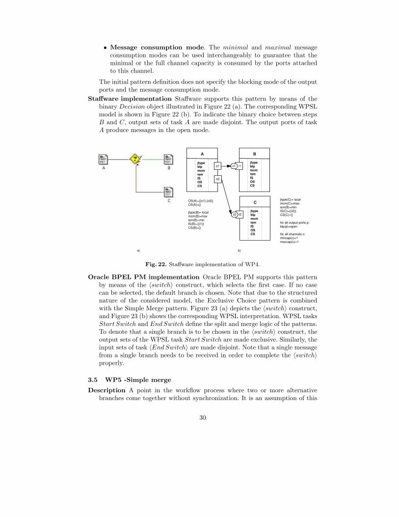
Staffware implementation Staffware supports this pattern by means of thebinary Decision object illustrated in Figure 22 (a). The corresponding WPSLmodel is shown in Figure 22 (b). To indicate the binary choice between stepsB and C, output sets of task A are made disjoint. The output ports of taskA produce messages in the open mode.
o1
A
jtype blp mcm ism IS OS CS
B
i1 c1 jtype blp mcm ism IS OS CS
C
i2 c2 jtype blp mcm ism IS OS CS
o2
OS(A)={{o1},{o2}} CS(A)={}
jtype(B)= local mcm(B)=max ism(B)=min IS(B)={{i1}} CS(B)={}
a) b)
jtype(C)= local mcm(C)=max ism(B)=min IS(C)={{i2}} CS(C)={}
for all output ports p: blp(p)=open
for all channels c: mincap(c)=1 maxcap(c)=1
Fig. 22. Staffware implementation of WP4.
Oracle BPEL PM implementation Oracle BPEL PM supports this patternby means of the 〈switch〉 construct, which selects the first case. If no casecan be selected, the default branch is chosen. Note that due to the structurednature of the considered model, the Exclusive Choice pattern is combinedwith the Simple Merge pattern. Figure 23 (a) depicts the 〈switch〉 construct,and Figure 23 (b) shows the corresponding WPSL interpretation. WPSL tasksStart Switch and EndSwitch define the split and merge logic of the patterns.To denote that a single branch is to be chosen in the 〈switch〉 construct, theoutput sets of the WPSL task Start Switch are made exclusive. Similarly, theinput sets of task 〈EndSwitch〉 are made disjoint. Note that a single messagefrom a single branch needs to be received in order to complete the 〈switch〉properly.
3.5 WP5 -Simple merge
Description A point in the workflow process where two or more alternativebranches come together without synchronization. It is an assumption of this
30

o1
Start Switch
jtype blp mcm ism IS OS CS
Assign_1
i1 c1 jtype blp mcm ism IS OS CS
Assign_3
i2 c2 jtype blp mcm ism IS OS CS
o2
OS(Start Switch)= {{o1},{o2},{o3}} CS(Start Switch)={}
jtype(Assign_1)= local mcm(Assign_1)=min ism(Assign_1)=min IS(Assign_1)={{i1}} OS(Assign_1)={{o4}} CS(Assign_1)={}
jtype(Assign_2)= local mcm(Assign_2)=min ism(Assign_2)=min IS(Assign_2)={{i3}} OS(Assign_2)={{o5}} CS(Assign_2)={}
jtype(Assign_3)= local mcm(Assign_3)=min ism(Assign_3)=min IS(Assign_3)={{i2}} OS(Assign_3)={{o6}} CS(Assign_3)={}
jtype(End Switch)= local mcm(End Switch)=min ism(End Switch)=min IS(End Switch)={{i4},{i5},{i6}} CS(End Switch)={}
for all channels c: mincap(c)=1 maxcap(c)=1
Assign_2
i3 c3 jtype blp mcm ism IS OS CS
o3
End Switch
i4 c4 jtype blp mcm ism IS OS CS
i5 c5
i6 c6
o4
o5
o6
a) b)
Fig. 23. Oracle implementation of WP4.
31

pattern that none of the alternative branches is ever executed in parallel (ifthis is not the case, then see WP8 (Multi-merge) or WP9 (Discriminator)).
Selected WPSL specification Figure 24 demonstrates the Simple Merge pat-tern.
Task t3
jtype blp mcm ism IS OS CS
Task t1
i1
jtype blp mcm ism IS OS CS
Task t2
jtype blp mcm ism IS OS CS
o2
o1
OS(t1)={{o1}} CS(t1)={}
OS(t2)={{o2}} CS(t2)={}
jtype(t3)= local mcm(t3)=min ism(t3)=min IS(t3)={{i1}} CS(t3)={}
for all ports p: blp(p)=open
mincap(c1)=1 maxcap(c1)=1
c1
Fig. 24. WP5 - Simple merge. Selected WPSL specification.
Task t3 is enabled after either task t2 or task t3 is executed. Tasks t1 and t2are connected to task t3 via an external safe channel c1. A message producedby an output port of either task t1 or t2 enables an input port i1 of task t3.This behavior is reflected by the minimal message consumption mode and theminimal channel capacity limited to 1. Enabling of the input port i1 of taskt3 is based on the messages currently available in the channel.
Alternative WPSL specifications The points of variations based on whichalternative configurations of the Simple Merge pattern can be based are listedbelow.
• Channel characteristics. Channel capacity : The capacity of channel c1 canbe bounded or unbounded depending on the number of messages the channelis allowed to store at once. To specify that multiple messages are requiredto enable an input port of task t3 the minimal capacity of the correspondingnon-safe channel must be set respectively.
• Blocking of output ports. Output ports can be set to the blocked or openmode to be used in combination with bounded or any type of channels re-spectively.
• Message consumption mode. In minimal message consumption mode thenumber of messages required to enable the channel (equivalent to the minimalchannel capacity) is consumed, the rest of the non-consumed messages arestored in the channel for subsequent task execution. To consume all messagesavailable in the channel, the message consumption mode should be set tomaximal.
32

Staffware implementation Staffware supports this pattern directly via Stepobjects in the configuration shown in Figure 25(a). The corresponding WPSLinterpretation is shown in Figure 25(b). Note that the enabling of task C isbased on the messages locally available in the safe channel c1. Step C willbe executed only once even if steps A and B would complete simultaneously,which is reflected by the open mode of the blocking mode of the outgoingchannels belonging to the corresponding WPSL tasks A and B.
C
jtype blp mcm ism IS OS CS
A
i1
jtype blp mcm ism IS OS CS
B
jtype blp mcm ism IS OS CS
o2
o1
OS(A)={{o1}} CS(A)={} OS(B)={{o2}} CS(B)={}
jtype(C)= local IS(C)={{i1},{i2}} mcm(C)=min ism(C)=max CS(C)={}
for all output ports p: blp(p)=open for all channels c: mincap(c)=1 maxcap(c)=1
c1
a) b)
i2 c2
Fig. 25. Staffware implementation of WP5.
Oracle BPEL PM implementation Oracle BPEL PM supports this patterndirectly using the 〈switch〉 construct depicted in Figure 23. Note that sincethis construct is of structured form, in Oracle BPEL PM the Simple Mergepattern is always used in combination with the Exclusive Choice pattern.This also guarantees that the pattern assumption that none of the alternativebranches (in the 〈switch〉 construct) ever executes in parallel. The descriptionof WPSL for the 〈switch〉 construct in the Exclusive Choice pattern is alsovalid in the context of the Simple Merge pattern.
3.6 WP6 -Multiple Choice
Description A point in the workflow process where, based on a decision or work-flow control data, a number of branches are chosen.
Selected WPSL specification Figure 26 illustrates the Multiple Choice pat-tern.
33

o1
Task t1
jtype blp mcm ism IS OS CS
Task t2
i1 c1 jtype blp mcm ism IS OS CS
Task t3
i2 c2 jtype blp mcm ism IS OS CS
o2
OS(t1)={{o1},{o2},{o1,o2}} CS(t1)={}
jtype(t2)= local mcm(t2)=min ism(t2)=min IS(t2)={{i1}} CS(t2)={}
jtype(t3)= local mcm(t3)=min ism(t3)=min IS(t3)={{i2}} CS(t3)={}
for all output ports p: blp(p)=open
for all channels c: mincap(c)=1 maxcap(c)=1
Fig. 26. WP6 - Multiple Choice. Selected WPSL specification.
After executing task t1, task t2 or task t3 is or both are executed. The actuallogic associated with the multiple choice is encapsulated in the output sets oftask t1, which specified that either one of two optional output ports or bothare selected for the message production. To make the distinction betweenthe execution pathes following task t1, the channels c1 and c2 are chosen tobe dedicated (local). The channels are safe and messages stored in them areconsumed in the minimal message consumption mode by task t2 and task t3.The setting of the input selection mode is omitted, since no option exists forselecting an input for tasks t2 and t3. The enabling of these tasks is basedon the messages currently available in the channels. Note that the originalpattern definition given in [5] does not consider the blocking mode of outputports. In the selected specification this parameter has been set to open.
Alternative WPSL specifications The points of variations describing alter-native configurations of the Multiple Choice pattern are listed below.
• Channel characteristics. Channel capacity : The capacity of channels c1 andc2 can be increased and set to bounded or unbounded depending on thenumber of messages the channel is allowed to store at once. To specify thatmultiple messages are required to enable an input port of tasks t2 and t3 theminimal capacity of the corresponding non-safe channels must be adjustedrespectively.
• Blocking of output ports. Depending on the type of the channels used,output ports can be set to the blocked or open mode.
• Message consumption mode. For safe channels, the minimal and maximalmessage consumption modes are equivalent. If the channels in use are boundedor unbounded, the minimal or maximal message consumption modes must be
34

selected to specify the limited or full message consumption from the channelrespectively.
Staffware implementation Staffware does not support this pattern directly.However, it can be implemented using a series of Decision steps which arebinary and correspond to exclusive OR-splits (see [24]).
Oracle BPEL PM implementation Oracle BPEL supports this pattern bymeans of the 〈flow〉 construct and links. Links are associated with everybranch. Branches become enabled when their transition conditions have beensatisfied. Note that the graphical notation of Figure 27 (a) does not show linksbetween the branches of the 〈flow〉, they are listed in the BPEL code. Theordering of activities by means of links is reflected in the logic defined overthe input and output sets of the corresponding tasks belonging to the WPSLspecification depicted in Figure 27 (b).
<flow name="Flow_1">
<links>
<link name="Link14"/>
<link name="Link13"/>
<link name="Link12"/>
</links>
<sequence name="Sequence_4">
<assign name="Assign_1">
<source linkName="Link12" transitionCondition=""/>
<source linkName="Link13" transitionCondition=" "/>
<source linkName="Link14" transitionCondition=" "/>
</assign>
</sequence>
<sequence name="Sequence_3">
<target linkName="Link13"/>
<assign name="Assign_4">
...
</assign>
</sequence>
<sequence name="Sequence_2">
<target linkName="Link12"/>
<assign name="Assign_3">
...
</assign>
</sequence>
<sequence name="Sequence_1">
<target linkName="Link14"/>
<assign name="Assign_2">
...
</assign>
</sequence>
</flow>
35

a)
o1
Assign_1
jtype blp mcm ism IS OS CS
Assign_4
i1 c1 jtype blp mcm ism IS OS CS
Assign_3
i2 c2 jtype blp mcm ism IS OS CS
o2
jtype(Assign_2)= local IS(Assign_2)={{i3}} OS(Assign_2)={{o6}} ism(Assign_2)=min mcm(Assign_2)=min CS(Assign_2)={}
jtype(End FLow)= local
IS(End Flow)={{i4,i5,i6}} ism(End Flow)=max mcm(End Flow)=min CS(End Flow)={}
for all channels c: mincap(c)=1 maxcap(c)=1
Assign_2
i3 c3 jtype blp mcm ism IS OS CS
End Flow
i4 c4 jtype blp mcm ism IS OS CS o3
o4
o5
o6
i5 c5
i6 c6
b)
OS(Assign_1)={{o1},{o2}, {o3},{o1,o2},{o1,o3}, {o2,o3},{o1,o2,o3}} CS(Assign_1)={}
jtype(Assign_4)= local IS(Assign_4)={{i1}} OS(Assign_4)={{o4}} ism(Assign_4)=min mcm(Assign_4)=min CS(Assign_4)={}
jtype(Assign_3)= local IS(Assign_3)={{i2}} OS(Assign_3)={{o5}} ism(Assign_3)=min mcm(Assign_3)=min CS(Assign_3)={}
Fig. 27. Oracle implementation of WP6.
36

3.7 WP7 -Synchronizing Merge
Description A point in the workflow process where multiple paths converge intoone single thread. If more than one path is taken, synchronization of the activethreads needs to take place. If only one path is taken, the alternative branchesshould reconverge without synchronization. It is an assumption of this patternthat a branch that has already been activated, cannot be activated again whilethe merge is still waiting for other branches to complete.
Selected WPSL specification Figure 28 demonstrates the Synchronizing Mergepattern.
Task t3
jtype blp mcm ism IS OS CS
Task t1
i1 c1
jtype blp mcm ism IS OS CS
Task t2 i1 c1
jtype blp mcm ism IS OS CS
o2
o1
OS(t1)={{o1}} CS(t1)={}
OS(t2)={{o2}} CS(t2)={}
jtype(t3)= future IS(t3)={{i1},{i2},{i1,i2}} mcm(t3)= min ism(t3)=max CS(t3)={}
for all output ports p: blp(p)=open
for all channels c: mincap(c)=1 maxcap(c)=1
Fig. 28. WP7 - Synchronizing Merge. Selected WPSL specification.
Task t3 is executed after executing task t1 or task t2 or both. In order tospecify that task t3 should wait until no more messages may arrive to the taskinputs, jtype parameter of this task is set to future. Since several sets fromthe input set of task t3 can be enabled simultaneously, the largest set must beselected, therefore the input selection mode is set to maximal. In combinationwith safe channels, the message consumption mode set to minimal, ensuresthat only one message must be consumed by each enabled port.
Alternative WPSL specifications The points of variation describing alterna-tive configurations of the Synchronizing Merge pattern are listed below.
• Channel characteristics. Channel capacity : The capacity of channels c1 andc2 can be increased and set to bounded or unbounded depending on the num-ber of messages the channel is allowed to store at once. To specify that multiplemessages are required to enable an input port(s) of task t3 the minimal ca-pacity of the corresponding non-safe channel must be set respectively.Channel positioning : local channels can be replaced by external ones withan additional requirement that access to the messages stored in the externalchannel is limited to a single (dedicated)task.
37

• Blocking of output ports. Depending on the type of the channels used,output ports can be set to the blocked or open mode.
• Message consumption mode. In the context of safe channels, the minimaland maximal message consumption modes are equivalent. If the channels inuse are bounded or unbounded, the minimal or maximal message consumptionmodes must be selected to specify the limited or full message consumptionfrom a channel respectively.
Staffware implementation Staffware does not support this pattern directly.However, similar behavior can be obtained by combining Decision constructsand complex routers on the inputs of the Wait object as it is shown in [24].
Oracle BPEL PM implementation Oracle BPEL PM supports this patternvia 〈flow〉 and links as described for the Multiple Choice pattern (see Fig-ure 27). Links with transition conditions are used to define which brancheswithin the 〈flow〉 construct are to be selected. The synchronization of branchesis done by the 〈flow〉 activity. The 〈flow〉 activity will only complete wheneach of its sub-activities has either completed or has been skipped. The con-tinuation of the process after the synchronizing merge can be placed after the〈flow〉 activity.
3.8 WP8 -Multiple Merge
Description A point in a workflow process where two or more branches re-converge without synchronization. If more than one branch is activated, theactivity following the merge is started for every activation of every incomingbranch (including concurrent instances).
Task t3
jtype blp mcm ism IS OS CS
Task t1
i1
jtype blp mcm ism IS OS CS
Task t2
jtype blp mcm ism IS OS CS
o2
o1
OS(t1)={{o1}} CS(t1)={}
OS(t2)={{o2}} CS(t2)={}
IS(t3)={{i1}} jtype(t3)= local mcm(t3)= min ism(t3)=min CS(t3)={}
for all output ports p: blp(p)=open
channel c1 is unbounded mincap(c1)=1
c1
Fig. 29. WP8 - Multiple Merge. Selected WPSL specification.
Selected WPSL specification Figure 29 illustrates the Multiple Merge pat-tern. Task t3 is executed each time the execution of task t1 or task t2 com-pletes. Messages arriving to the inputs of task t3 are aggregated in the un-
38

bounded channel c1, while task t3 is in the active state, thus allowing the taskto be enabled and executed again. Since multiple messages can be stored inthe channel c1 and each of the messages must enable task t3, the messageconsumption mode of this task is set to minimal. The minimal capacity of thechannel, which is limited to 1, is consumed by the input port i1 of task t3each time any of tasks t1 or t2 completes. Note that output ports of task t1and task t2 are open and never become blocked, since the maximal capacityof the unbounded channel c1 can never be reached.
Alternative WPSL specifications The points of variations describing alter-native configurations of the Multiple Merge pattern are listed below.
• Channel characteristics. Channel capacity : The capacity of the channelc1 can be bounded to the maximal number of messages the channel isable to store at once. It may be necessary to amend the blocking type ofthe output ports of task t1 and task t2 to specify whether the tasks areallowed to complete if the maximal capacity of the outgoing channels hasbeen reached. The minimal channel capacity can be also modified, whichwill have an influence on the status of the enabling of task t3.
• Input Sets. If the external channel c1 is replaced by two local channelsfor a dedicated transfer of messages from tasks t1 and t2, the input setsof task t3 should be made disjoint. To guarantee that task t3 will beexecuted upon enabling of each port, but not once if both input portsare enabled, the input consumption mode should be set to minimal andmessages should be consumed from the channels in the minimal messageconsumption mode.
Staffware implementation This pattern is not supported by Staffware directly.However, similar behavior can be obtained by duplicating task C and placingit on two branches with tasks A and B respectively as it is shown in [24].
Oracle BPEL PM implementation Oracle BPEL PM offers the facilities toimplement this pattern by means of an event handler attached to the scopein which multiple branches reside. In every branch enclosed in the 〈flow〉construct, an 〈invoke〉 activity should be placed to invoke a synchronousdummy service. The response message produced by this dummy service needsto be processed by an event handler attached to the scope outer of the 〈flow〉construct. This results in an event handler being executed each time a branchcompletes. For some reason, the event handlers attached to the process scopeseem to be unable to respond to messages. Since the desired behavior hasn’tbeen achieved by means of event handlers, this pattern is not considered tobe supported. Further details on this issue are available in [18].
3.9 WP9a -Discriminator
Description The discriminator is a point in a workflow process that waits forone of the incoming branches to complete before activating the subsequentactivity. From that moment on it waits for all remaining branches to complete
39

and “ignores” them. Once all incoming branches have been triggered, it resetsitself so that it can be triggered again (which is important otherwise it couldnot really be used in the context of a loop).
Selected WPSL specification Figure 30 illustrates the default WPSL configi-ration of the Discriminator pattern.
Task t3
jtype blp mcm ism IS OS CS
Task t1
i1
jtype blp mcm ism IS OS CS
Task t2
jtype blp mcm ism IS OS CS
o2
o1
OS(t1)={{o1}} CS(t1)={}
OS(t2)={{o2}} CS(t2)={}
jtype(t3)= local IS(t3)={{i1}} mcm(t3)= min ism(t3)=min CS(t3)={t1, t2, c1}
channel c1 is unbounded mincap(c1)=1
CS(t3)
c1
Fig. 30. WP9a - Discriminator. Selected WPSL specification.
Task t3 is executed after task t1 or task t2 completed. When task t3 terminatesit removes messages inside of the tasks and in channels, thus disabling anyremaining triggers. After the messages from the cancellation set are removed,task t3 can be triggered again. Although multiple messages can be placedconcurrently on the input channel of task t3, only one message is consumedfrom it. This is reflected by setting the minimal channel capacity to 1 and themessage consumption mode to minimal.
Alternative WPSL specifications The points of variation describing alterna-tive configurations of the Discriminator pattern are listed below.
• Channel characteristics. Channel capacity : The capacity of the channelc1 can be bounded to the maximal number of messages the channel is ableto store at once. If the capacity of the channel is bounded, the minimalmessage capacity of the channel should be set to the number of messagesrequired to enable the input port connected to this channel.
In this case, the blocking type of the output ports of task t1 and task t2should be amended to specify whether the tasks are allowed to completewhen the maximal capacity of the outgoing channels has been reached.The minimal channel capacity can be also modified, which will affect theenabling status of the channel c1 and task t3.
40

• Blocking of output ports. Depending on the type of channels used,output ports can be set to the blocked or open mode. Safe and boundedchannels can be connected to the open and blocked output ports, whileunbounded channels can only be connected to open output ports respec-tively.
• Message consumption mode. If the channels in use are bounded orunbounded, then the minimal or maximal message consumption modesmust be selected to specify the limited or full message consumption fromthe channels respectively.
• Input Sets. If the external channel c1 is replaced by two local channels fora dedicated transfer of messages from tasks task t1 and task t2, the inputsets of task t3 should be made disjoint. To guarantee that task t3 will beexecuted upon enabling of each port, and not once (if both input portsare enabled), the input consumption mode and the message consumptionmode should be set to minimal.
• Cancellation Set. The cancellation set defined for task t3 can be ex-tended depending on the context in which the discriminator is used.
Staffware implementation Staffware does not support this pattern directly.However, a work around solution can be constructed using a script and Decisionconstruct as it is shown in [24].
Oracle BPEL PM implementation Oracle BPEL PM does not support thispattern.
3.10 WP9b -N-out-of-M join
Description N-out-of-M Join is a point in a workflow process where M parallelpaths converge into one. The subsequent activity should be activated once Npaths have completed. Completion of all remaining paths should be ignored.Similarly to the discriminator, once all incoming branches have ”fired”, thejoin resets itself so that it can fire again.
Selected WPSL specification Figure 31 demonstrates the N-out-of-M join pat-tern.
Configuration shown is for a 2-out-of-3 join, however it can be easily extendedto any required number of inputs. Task t4 is executed after any two tasksfrom t1, t2 and t3 have completed. Task t4 consumes only 2 messages, whichis ensured by setting the minimal message capacity of the channels c1, c2and c3 to 1 and the message consumption mode to minimal. The input setspecifies that task t4 can be enabled if any two input ports have been enabled.In the case where more than two ports are enabled, two ports are arbitrarilyselected. This is reflected by the input selection mode which is set to random.After task t4 completes, the discriminator is reset, by removing the messagesremaining in locations specified in the cancellation set of task t4.
41

CS(t3)
Task t4
jtype blp mcm ism IS OS CS
Task t2
i1
jtype blp mcm ism IS OS CS
Task t3
i2
jtype blp mcm ism IS OS CS
o1
o3
i3
OS(t1)={{o1}} CS(t1)={}
OS(t2)={{o2}} CS(t2)={}
OS(t3)={{o3}} CS(t3)={}
IS(t4)={{i1,i2},{i1,i3}, {i2,i3}} CS(t4)={c1, c2, c3, t1, t2, t3} jtype(t4)= local mcm(t4)= min ism(t4)= ran
For all output ports p: blp(p)=open
All channels c are unbounded mincap(c)=1
Task t1
jtype blp mcm ism IS OS CS
o1
c3
c1
c2
Fig. 31. WP9b - 2-out-of-3 join. Selected WPSL specification.
Alternative WPSL specifications The points of variation describing alterna-tive configurations of the N-out-of-M join pattern are the same as for theDiscriminator pattern. In addition, the following variation points apply:
• Input Sets. The current definition of the N-out-of-M join pattern cap-tures only an arbitrary combination of branches. The composition of theinput sets of task t4 for enabling of the N-out-of-M join can be can betuned to any required combination of inputs through the set restrictionor extension.
• Cancellation Set. The N-out-of-M join can be used with or without acancellation set. If at the time of task completion non-consumed messagesmust be removed from the input locations, the cancellation set shouldexplicitly list these locations. Conversely, if non-consumed messages mustbe preserved for the subsequent task enabling, the cancellation set shouldremain empty.
Staffware implementation Staffware does not support this pattern directly.However, the work around solution can be found using a script, a counter forinputs and Decision construct as it is described in [24].
Oracle BPEL PM implementation Oracle BPEL PM does not support thispattern.
42

3.11 WP10 -Arbitrary cycles
Description A point in a workflow process where one or more activities can bedone repeatedly.
Selected WPSL specification Figure 32 illustrates a possible configuration ofthe Arbitrary Cycles pattern.
Task t2
jtype blp mcm ism IS OS CS
Task t1
i1
jtype blp mcm ism IS OS CS
Task t4
i2
jtype blp mcm ism IS OS CS
o6 o1
o3
Task t3
jtype blp mcm ism IS OS CS
o4
i4 o5
o2 i3 i5
OS(t1)={{o1}} IS(t2)={{i1},{i2}} IS(t3)={{i3},{i4}} IS(t4)={{i5}} CS(t1)={} CS(t2)={} CS(t3)={} CS(t4)={}
OS(t2)={{o2},{o3}} OS(t3)={{o4},{o5}} OS(t4)={{o6}} ism(t2)=min ism(t3)=min ism(t4)=min mcm(t2)=min mcm(t3)=min mcm(t4)=min
for all output ports p: blp(p)=open for all channels c: mincap(c)=1
maxcap(c)=1
c3 c1
c2 c4
c5
Fig. 32. WP10 - Arbitrary cycles. Selected WPSL specification.
After task t1 completes, tasks t2, t3 and t4 can be executed multiple timesdepending on the choice made after tasks t3 and t4 completed respectively.The model presented allows for multiple entry and output points from theloop. The choice of branches for the subsequent enabling on completion oftasks t2, t3, and t4 is specified in the output sets of the corresponding tasks.
Alternative WPSL specifications Alternative representations of the ArbitraryCycles pattern depend on the number of tasks in the loop, the number of entryand output points, additional requirements and constraints set on the tasksthat can be expressed by means of the task attributes.
The Arbitrary Cycles pattern is a generic representation of the looping struc-tures, which in special cases can be implemented as ”while-do” and ”repeat-until” strategies.
Staffware implementation Staffware supports this pattern allowing multipleintertwined cycles as it shown in Figure 33(a). The corresponding WPSLnotation is shown in Figure 33(b). After completing step B the choice ismade whether to execute this step again or to proceed further. This choice isvisualized by means of optional output ports and exclusive output sets of taskB. The input ports of task B are made optional respectively and the inputsets can be enabled by messages received on any of the input ports.
43

B
jtype blp mcm ism IS OS CS
A
i1
jtype blp mcm ism IS OS CS
i2
o1
o3
C
jtype blp mcm ism IS OS CS
o2 i3
OS(A)={{o1}} IS(B)={{i1},{i2}} IS(C)={{i3}} CS(A)={} jtype(B)=local jtype(C)=local
ism(B)=max ism(C)=min for all output ports p: blp(p)=open OS(B)={{o2},{o3}} for all channels c: mincap(c)=1
maxcap(c)=1
c3 c1
c2
(a) (b)
Fig. 33. Staffware implementation of WP10.
Oracle BPEL PM implementation Oracle BPEL PM supports this patternpartially via the 〈while〉 construct depicted in Figure 34(a). The behavior ofthis construct is represented in WPSL in Figure 34(b). After task Assign2
completes, the decision is made whether to execute this task again (by pro-ducing a message on the output port o1) or to exit the loop (by producing amessage on the output port o2).
Assign_2
jtype blp mcm ism IS OS CS
i1
IS(Assign_2)={{i1}} OS(Assign_2)={{o1},{o2}} jtype(Assign_2)=local ism(Assign_2)=min mcm(Assign_2)=min CS(Assign_2)={}
o2
c1
c2
o1
a) b)
Fig. 34. Oracle implementation of WP10.
3.12 WP11 -Implicit termination
Description A given subprocess should be terminated when there is nothing elseto be done. In other words, there are no active activities in the workflow andno other activity can be made active (and at the same time the workflow isnot in deadlock).
Selected WPSL specification In order to represent this pattern by means ofWPSL, we relax the notion of soundness of the GWF-net, allowing multiple
44

end-point channels, the enabling of which does not lead to immediate casetermination but is postponed until no active tasks are left which still mayexecute or need to complete.
Task ET depicted in Figure 35 can be used to denote this pattern. ET makesimplicit termination explicit and takes as inputs the end-point channels of aGWF-net, synchronizing them all using the information about future possiblestates. To complete the case, all messages from all end-point channels areconsumed and one message is produced to the et end-channel.
e1
e2
ET
jtype blp mcm ism IS OS CS
o1 et
i1
i2
eN
iN ...
IS(ET)={{i1}, {i2}, ...,{iN}, {i1,i2}, ...,{i1,i2, ...iN}} OS(ET)={{o1}} CS(ET)={}
jtype(ET)= future mcm(ET)=max ism(ET)=max
blp(o1)=open for all channels c: mincap(c)=1
maxcap(c)=1
Fig. 35. WP11 - Implicit termination. The WPSL notation.
Staffware implementation Staffware suports this pattern directly. The work-flow instance terminates if all of the corresponding branches have terminated.
Oracle BPEL PM implementation Oracle BPEL PM supports this patterndirectly by the 〈flow〉 construct, which terminates when no activities withinits body can be triggered and executed any more.
3.13 WP12 -Multiple Instances Without Synchronization
Description Within the context of a single case (i.e., workflow instance) multipleinstances of an activity can be created, i.e., there is a facility to spawn off newthreads of control. Each of these threads of control is independent of otherthreads. Moreover, there is no need to synchronize these threads.
Selected WPSL specification Figure 36 demonstrates the Multiple InstancesWithout Synchronization pattern.
After task t1 completes task t3 is initiated one or more times. The instancesof task t3 are not synchronized, which is ensured by means of task t2 that isimplemented in the body of a loop. At the completion of task t2, either taskt3 is triggered and task t2 will be initiated again, or task t3 is initiated andthe flow of control is passed further via an external channel c3. Note, that torealize this behavior, the output ports of task t2 are chosen to be optional,and the output logic of this task is captured by the output sets attribute. Inthe given confuguration unbounded channels are attached to the open outputports.
Alternative WPSL specifications The variation points of the MI withoutSynchronization pattern are listed below:
45

Task t2
jtype blp mcm ism IS OS CS
Task t1
i1
jtype blp mcm ism IS OS CS
o1 o1
o2
OS(t1)={{o1}} IS(t2)={{i1}} IS(t3)={{i2}} jtype(t2)=local jlocal(t3)=local
All channels c are unbounded ism(t2)=min ism(t3)=min mincap(c)=1 mcm(t2)=min mcm(t3)=min
OS(t2)={{o1, o2}, {o2, o3}} For all output ports p: blp(p)=open
Task t3
jtype blp mcm ism IS OS CS
i2
o3
c1
c3
c2
Fig. 36. WP12 - Multiple Instances Without Synchronization
• Channel characteristics. Channel capacity : The capacity of the chan-nels can be set to bounded or unbounded depending on the number ofmessages the channel is able to store at once. The minimal channel ca-pacity of the channel should be set conjunction with the maximal channelcapacity.
• Blocking of output ports. Depending on the type of the channels used,output ports can be set to the blocked or open mode. Safe and boundedchannels can be connected to the open and blocked output ports, whileunbounded channels only to the open output ports.
• Message consumption mode. If the channels in use are bounded orunbounded, the minimal or maximal message consumption modes mustbe selected to specify the limited or full message consumption from thechannels respectively.
Staffware implementation Staffware does not support this pattern directly.However, a sub-case can be used as a wrapper for an activity multiple instancesof which need to be instantiated as described in [24].
Oracle BPEL PM implementation Oracle BPEL PM supports this patternusing the 〈invoke〉 construct within the body of a 〈while〉 loop as shown inFigure 37(a). The corresponding WPSL interpretation is given in Figure 37(b).
3.14 WP13 -Multiple Instances with a Priori Design time Knowledge
Description For one process instance an activity is enabled multiple times. Thenumber of instances of a given activity for a given process instance is knownat design time. Once all instances are completed some other activity needs tobe started.
46

Assign_2
jtype blp mcm ism IS OS CS
i1
IS(Assign_2)={{i1}} IS(Invoke_1)={{i2}} OS(Assign_2)={{o1}} OS(Invoke_1)={{o2}, {o3}} jtype(Assign_2)= local jtype(Invoke_1)= local mcm(Assign_2)=min mcm(Invoke_1)=min ism(Assign_2)=min ism(Invoke_1)=min CS(Assign_2)={} CS(Assign_2)={}
Invoke_1
jtype blp mcm ism IS OS CS
i2
o3
c1
c3
c2 o2
o1
(a) (b)
Fig. 37. Oracle implementation of WP12.
Selected WPSL specification Figure 38 demonstrates the default WPSL con-figuration of the Multiple Instances with a priori design time knowledge pat-tern. To distinguish between different types of multiple instance tasks weintroduce some additional graphical notations. The number of instances thatare to be created is denoted as N and listed in the list of the task attributes.The label DTK reflects that the number of instances of the MItask to becreated is known at design-time. The execution of this task corresponds tothe enabling of N instances of a given task in parallel.
MI task
jtype blp mcm ism IS OS CS N
o1 i1
DTK
Fig. 38. WP13 - Multiple Instances with a Priori Design time Knowledge. The WPSLspecification.
Alternative WPSL specifications An alternative means of specification is toduplicate a task as many times as many task instances are required and touse them together with the Parallel Split and Synchronization patterns asillustrated in Figure 39. After task t1 completes and before task t3 may com-mence, two instances of task t2 need to be executed. Since all instances needto complete before task t3 commences, task t3 input sets specifies that both
47

Task t1
jtype blp mcm ism IS OS CS
o1
o2
Task t3
jtype blp mcm ism IS OS CS
i3 c3
i4 c4
Task t2 (1)
jtype blp mcm ism IS OS CS
o3 i1 c1
Task t2 (2)
jtype blp mcm ism IS OS CS
o4 i2 c2 OS(t1)={{o1,o2}} IS(t2(2))={{i2}} CS(t1)={} OS(t2(2))={{o2}}
jtype(t2(2))=local IS(t2(1))={{i1}} ism(t2(2))=min OS(t2(1))={{o1}} mcm(t2(2))=min jtype(t2 (1))=local CS(t2(2))={} ism(t2(1))=min mcm(t2(1))=min IS(t3)={{i3, i4}} CS(t2(1))={} jtype(t3)= local
ism(t3)=max for all output ports p: mcm(t3)=min blp(p)=open CS(t3)= {} for all channels c: mincap(c)=1 maxcap(c)=1
Fig. 39. WP13 - Multiple Instances with a Priori Design time Knowledge. An alternativeWPSL specification.
input ports must be enabled. Thus, task t3 plays a role of a synchronizer asdescribed in the Synchronization pattern, and task t1 represents the ParallelSplit.
The task attributes set for the MI task are identical for all instances of thistask. The following attributes may be varied from the settings described above:type of channels, message consumption mode, input sets, and blocking mode.The values they can take are the same as those described for the Parallel Splitand Synchronization patterns.
Staffware implementation Staffware supports this pattern through combina-tion of splits and joins as illustrated in Figure 40. Multiple instances of atask B are achieved by replicating this task and enabling all instances simul-taneously. The synchronization of these tasks is done as the Synchronizationpattern describes.
Oracle BPEL PM implementation Oracle BPEL PM supports this patternby replicating an activity on each of the branches of the 〈flow〉 activity. Thereshould be one branch for each activity instance. See the Parallel Split patternfor the details of the configuration of the 〈flow〉 activity.
3.15 WP14 -Multiple Instances with a Priori Runtime Knowledge
Description For one case an activity is enabled multiple times. The numberof instances of a given activity for a given case varies and may depend oncharacteristics of the case or availability of resources, but is known at some
48

A
jtype blp mcm ism IS OS CS
o1
o2
B (3)
jtype blp mcm ism IS OS CS
i3 c3
B (1)
jtype blp mcm ism IS OS CS
i1 c1
B (2)
jtype blp mcm ism IS OS CS
i2 c2
For all output ports p: blp(p)=open
For all channels c: mincap(c)=1 maxcap(c)=1
o3
(a) (b)
OS(A)={{o1,o2, o3}} CS(A)={}
For all tasks B: jtype(B)=local ism(B)=min mcm(B)=min CS(B)={}
IS(B(1))={{i1}} IS(B(2))={{i2}} IS(B(3))={{i3}}
Fig. 40. Staffware implementation of WP13.
stage during runtime, before the instances of that activity have to be created.Once all instances are completed some other activity needs to be started.
Selected WPSL specification Figure 41 illustrates the default WPSL config-uration of the Multiple Instances with a priori runtime knowledge pattern.The number of instances that are to be created is denoted as N and listedin the list of the task attributes. The label RTK means that the number ofinstances of the MItask to be created is known at run-time. The execution ofthis task corresponds to the enabling of N instances of a given task in parallel.
MI task
jtype blp mcm ism IS OS CS N
o1 i1
RTK
Fig. 41. WP14 -Multiple Instances with a Priori Runtime Knowledge The WPSL spec-ification.
Alternative WPSL specifications Figure 42 shows how to depict the sequen-tial initiation of the task instances.
After completion of task t1, task t2 needs to be executed several times. As-suming that the information regarding the number of instances of task t2
49

Task t2
jtype blp mcm ism IS OS CS
Task t1
i1
jtype blp mcm ism IS OS CS
o1 o1
o2
OS(t1)={o1} IS(t2)={i1} CS(t1)={} OS(t2)={{o1}, {o2}}
jtype(t2)= local for all output ports p: blp(p)=open mcm(t2)=min for all channels c: CS(t2)={}
mincap(c)=1 maxcap(c)=1
c1
c2
Fig. 42. WP14 -Multiple Instances with a Priori Runtime Knowledge An alternativeWPSL notation.
becomes available at some stage during run-time, it can be incorporated intothe guard of task t2 and/or data conditions associated with enabling of theoutput ports. In this configuration, task t2 is encapsulated within a loop,which imposes the sequential execution of the instances of task t2.
Staffware implementation Staffware does not support this pattern directly.However, it allows an activity to be mapped to a sub-case and use a “multiplesub-procedure call-step” in combination with dynamic array assignments asit is described in [24].
Oracle BPEL PM implementation Standard BPEL does not support thispattern, however Oracle BPEL PM has implemented the 〈flowN〉 constructwhich supports it (see Figure 43). Note that although for creation of instances,〈flowN〉 uses run-time information, the actual execution of instances is donesequentially (thus corresponding to the behavior demonstrated in Figure 42).
Assign_2
jtype blp mcm ism IS OS CS N
RTK
i1 o1 c1 c1
(a) (b)
Fig. 43. Oracle implementation of WP14.
50

3.16 WP15 -Multiple Instances without a Priori Runtime Knowledge
Description For one case an activity is enabled multiple times. The numberof instances of a given activity for a given case is not known during designtime, nor is it known at any stage during runtime, before the instances ofthat activity have to be created. Once all instances are completed some otheractivity needs to be started. The difference with Pattern 14 is that even whilesome of the instances are being executed or already completed, new ones canbe created.
Selected WPSL specification To express this pattern in WPSL, we introducetwo types of blocks as shown in Figure 44. Blocks (a) and (b) contain labelsD and S denoting dynamic and static modes for creating task instances. Indynamic mode, task instances can be created while other instances are active.In static mode, all task instances are created at once. We extend the listof task attributes for these blocks with the following three parameters: min,max, threshold. Parameters min, max, threshold correspond to the minimumnumber of instances initiated, the maximum number of instances initiated andthe threshold value which indicates how many instances must complete beforethe process can continue.
MI Task
jtype blp mcm ism IS OS CS
o1 i1
No RTK D
MI Task
jtype blp mcm ism IS OS CS
o1 i1
No RTK S
min(MI Task) max(MI Task) threshold(MI Task )
Fig. 44. WP15 -Multiple Instances without a Priori Runtime Knowledge. The WPSLnotation.
Staffware implementation Staffware does not support this pattern directly.
Oracle BPEL PM implementation Oracle BPEL PM offers no direct sup-port for this pattern.
3.17 WP16 -Deferred choice
Description A point in the workflow process where one of several branches ischosen. In contrast to the XOR-split, the choice is not made explicitly (e.g.based on data or a decision) but several alternatives are offered to the environ-ment. However, in contrast to the AND-split, only one of the alternatives isexecuted. This means that once the environment activates one of the branchesthe other alternative branches are withdrawn. It is important to note that thechoice is delayed until the processing in one of the alternative branches isactually started, i.e. the moment of choice is as late as possible.
51

Selected WPSL specification Figure 45 illustrates the Deferred Choice pat-tern.
o1
Task t1
jtype blp mcm ism IS OS CS
Task t2
i1 jtype blp mcm ism IS OS CS
Task t3
i2 jtype blp mcm ism IS OS CS
OS(t1)={{o1}} CS(t1)={}
IS(t2)={{i1}} jtype(t2) =local ism(t2)=min mcm(t2)=min CS(t2)={}
IS(t3))={{i2}} jtype(t3) =local ism(t3)=min mcm(t4)=min CS(t3)={}
blp(o1)=open mincap(c1)=1 maxcap(c1)=1
c1
Fig. 45. WP16 - Deferred choice. Selected WPSL specification.
Task t1 is followed either by task t2 or by task t3. To visualize the non-deterministic choice that is to be made, task t2 and task t3 are connected toa single external channel, thus sharing the messages stored in it. When theminimal capacity of the channel is reached, both task t2 and task t3 becomeenabled. However, a message can be consumed only by one task at a time.Therefore, after the message from the channel c1 has been consumed by anyof task t2 or task t3, the other task becomes disabled.
Alternative WPSL specifications Alternative configurations of the DeferredChoice pattern may use all variants of the channel capacity, channel position-ing, and blocking mode of the output ports as indicated for the ExclusiveChoice pattern.
Staffware implementation Staffware does not support this pattern directly.However, it can be implemented by means of a parallel split and a withdrawas it shown in [24]).
Oracle BPEL PM implementation Oracle BPEL PM supports this patterndirectly via the 〈pick〉 construct (see Figure 46)(a), which allows only oneof several possible activities or (a set of activities) to be executed based onthe type of message received. Alternatively, the 〈pick〉 construct allows a timetrigger to be specified for the timeouts which cancel all other alternative tasks.The WPSL specification corresponding to the 〈pick〉 construct is shown inFigure 46(b). For the sake of convenience we abstracted from the modellingof the time trigger.
3.18 WP17 -Interleaved Parallel Routing
Description A set of activities is executed in an arbitrary order: each activity inthe set is executed, the order is decided at run-time, and no two activities are
52

Assign_2
jtype blp mcm ism IS OS CS
i1 o1
c1
Assign_3
jtype blp mcm ism IS OS CS
i2 o2
Assign_4
jtype blp mcm ism IS OS CS
i3 o3
c2
IS(Assign_3)={{i2}} OS(Assign_3)={{o2}} jtype(Assign_3)= local ism(Assign_3)=min mcm(Assign_3)=min CS(Assign_3)=min
IS(Assign_4)={{i3}} OS(Assign_4)={{o3}} jtype(Assign_4)= local ism(Assign_4)=min mcm(Assign_4)=min CS(Assign_4)=min
(a) (b)
IS(Assign_2)={{i1}} OS(Assign_2)={{o1}} jtype(Assign_2)= local ism(Assign_2)=min mcm(Assign_2)=min CS(Assign_2)=min
Fig. 46. Oracle implementation of WP16.
executed at the same moment (i.e. no two activities are active for the sameworkflow instance at the same time).
Selected WPSL specification Figure 47 illustrates the Interleaved Parallel Rout-ing pattern.
Task t2 and task t3 can be executed in any order after task t1 has completedbut before task t4 has commenced. To realize such a behavior, an externalchannel c3 is used to ensure that the execution of task t2 and task t3 ismutually exclusive. To enable both task t2 and task t3 concurrently, taskt1 is realized according to the Parallel Split pattern, and task t4 is realizedaccording to the Synchronization pattern.
Alternative WPSL specifications This pattern allows a partial order to bespecified over the sequence in which tasks are executed. This can be achievedby modifying the input sets, the input selection mode and the message con-sumption mode of the respective tasks (in this case task t2 and task t3). Inaddition, the number of tasks involved in the interleaved parallel routing, canbe increased.
Staffware implementation Staffware does not support this pattern directly(see [24]).
Oracle BPEL PM implementation Oracle BPEL PM does not support thispattern (see [18]).
53

Task t2
jtype blp mcm ism IS OS CS
Task t1
jtype blp mcm ism IS OS CS
o1
o4
o3
Task t3
jtype blp mcm ism IS OS CS
o6
i1 c1
i4 c2
Task t4
jtype blp mcm ism IS OS CS
i5 c4
i7 c6
OS(t1)={{o1,o2,o3}} CS(t1)={}
jtype(t2)=local IS(t2)={{i1,i2}} ism(t2)=max mcm(t2)=min OS(t2)={{o4,o5}} CS(t2)={}
jtype(t3)=local IS(t3)={{i3,i4}} ism(t3)=max mcm(t3)=min OS(t3)={{o6, o7}} Cs(t3)={}
o2 i6 c5
i2
i3
o7
o5
c3
jtype(t4)=local IS(t4)={{i5, i6, i7}} ism(t4)=max mcm(t4)=min CS(t4)={}
For all output ports p: blp(p)=open
For all channels c: mincap(c)=1 maxcap(c)=1
Fig. 47. WP17 - Interleaved Parallel Routing. Selected WPSL specification
3.19 WP18 -Milestone
Description The enabling of an activity depends on the case being in a specifiedstate, i.e. the activity is only enabled if a certain milestone has been reachedwhich did not expire yet. Consider three activities named A, B and C. ActivityA is only enabled if activity B has been executed and C has not been executedyet, i.e. A is not enabled before the execution of B and A is not enabled afterthe execution of C.
Selected WPSL specification Figure 48 demonstrates the Milestone pattern.
In this notation, the Milestone is modelled by means of an external channelc2. Task t5 performs the role of testing the milestone if task t7 has not beenexecuted yet. If the milestone (in form of a message) in the channel c2 is notavailable, and task t4 has completed, task t5 cannot be executed yet. As aresult a by-pass is taken, executing task t6. After the execution of task t6,when a message is placed in channel c2, task t5 cannot be executed anymore.The described logic is incorporated into the input and output sets of thecorresponding tasks.
Alternative WPSL specifications The WPSL specification presented in Fig-ure 48 allows the variations of channel capacity, although the positioning ofthe channel corresponding to the milestone must be preserved.
Staffware implementation Staffware does not support this pattern.
54

1) Task 7
jtype blp mcm ism IS OS CS
Task 2
jtype blp mcm ism IS OS CS
o3
i7
For all tasks t: mcm(t)=min ism(t)=max CS(t)={}
For all channels c: mincap(c)=1 maxcap(c)=1
1) Task 5
jtype blp mcm ism IS OS CS
o6 i4
1) Task 6
jtype blp mcm ism IS OS CS
o8 i6
i5 o7
i8 Task 3
jtype blp mcm ism IS OS CS
o4
i1
i2
Task 1
jtype blp mcm ism IS OS CS
o1
o2
Task 4
jtype blp mcm ism IS OS CS
o5 i3
c1
c2
c1 c1
OS(t1)={{o1,o2}} IS(t2)={{i1}} OS(t2)={{o3}} IS(t3)={{i2}} OS(t3)={{o4}} IS(t4)={{i3}} OS(t4)={{o5}} IS(t5)={{i4,i5}} OS(t5)={{o6,o7}} IS(t6)={{i6}} OS(t6)={{o8}} IS(t7)={{i7,i8}}
Fig. 48. WP18 -Milestone. Selected WPSL specification.
55

Oracle BPEL PM implementation Oracle BPEL PM offers no direct sup-port for this pattern, however some specific implementations are given in [18].
3.20 WP19 -Cancel Activity
Description An enabled activity is disabled, i.e. a thread waiting for the execu-tion of an activity is removed.
Selected WPSL specification Figure 49 demonstrates the default WPSL no-tation of the Cancel Activity pattern.
Cancel
jtype blp mcm ism IS OS CS
o1
Task t1
jtype blp mcm ism IS OS CS
o1 i1 c1
CS(Cancel)={c1,t1}
Fig. 49. WP19 -Cancel Activity. The WPSL notation.
Execution of task Cancel results in the termination of task t1 and removal ofmessages from its incoming channels. The locations from which the messagesshould be removed are specified in the cancellation set of task Cancel.
The definition of the Cancel Activity pattern treats a task as an atomic actionand requires messages to be removed only from the incoming channels and onlysupports the cancelling of enabled tasks. The WPSL notation allows the scopeof the cancellation to be extended. First of all, it incorporates the internal stateof a task into the cancellation. Secondly, by extending the cancellation set, anarbitrary set of tasks and channels can be specified, thus allowing to cancel aregion instead of just a single task.
Staffware implementation Staffware supports this pattern by means of a withdrawas illustrated in Figure 50(a). A trigger arriving on the top input of step Awithdraws this task, so that it won’t be executed any more. In terms of WPSLthis corresponds to cancelling task A.
Oracle BPEL PM implementation An Oracle BPEL PM provides supportfor this pattern by means of a scope (see Figure 51(a)), a fault and a fault
56

Cancel
jtype blp mcm ism IS OS CS
A
jtype blp mcm ism IS OS CS
CS(Cancel)={A}
(a) (b)
Fig. 50. Staffware implementation of WP19.
handler. The scope is used as wrapper for an activity that should be cancelled.The fault handler is needed to catch the fault message which is to be thrownwhen the client cancels the activity. The corresponding WPSL notation isshown in Figure 51(b).
Cancel
jtype blp mcm ism IS OS CS
Wait
jtype blp mcm ism IS OS CS
CS(Cancel)={Wait}
(a) (b)
Fig. 51. Oracle implementation of WP19.
3.21 WP20 -Cancel Case
Description A case, i.e. workflow instance, is removed completely (i.e., evenif parts of the process are instantiated multiple times, all descendants areremoved).
Selected WPSL specification Figure 52 demonstrates the Cancel Case pat-tern.
Execution of task Cancel results in the cancellation of a case, i.e. all messagesare removed from all channels and all active tasks are terminated. The rangeof cancellation is specified in the cancellation set of the Cancel task.
57
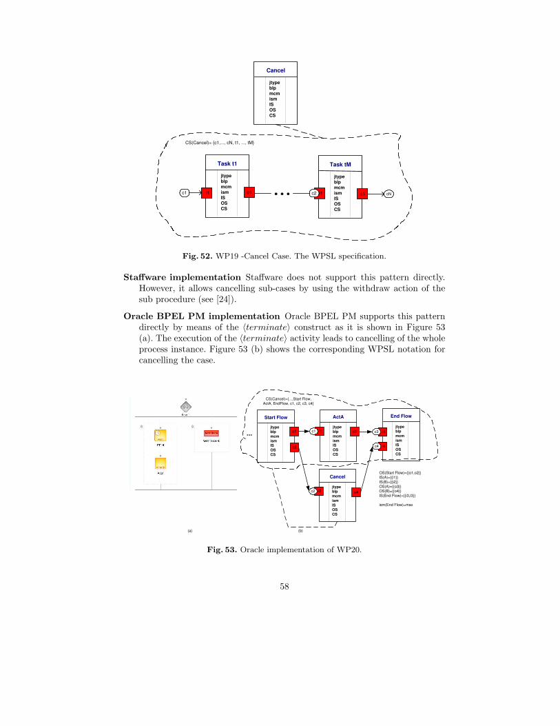
Cancel
jtype blp mcm ism IS OS CS
Task t1
jtype blp mcm ism IS OS CS
o1 i1
Task tM
jtype blp mcm ism IS OS CS
o1 i1 c2 c1 cN
CS(Cancel)= {c1,..., cN, t1, ..., tM}
Fig. 52. WP19 -Cancel Case. The WPSL specification.
Staffware implementation Staffware does not support this pattern directly.However, it allows cancelling sub-cases by using the withdraw action of thesub procedure (see [24]).
Oracle BPEL PM implementation Oracle BPEL PM supports this patterndirectly by means of the 〈terminate〉 construct as it is shown in Figure 53(a). The execution of the 〈terminate〉 activity leads to cancelling of the wholeprocess instance. Figure 53 (b) shows the corresponding WPSL notation forcancelling the case.
End Flow
jtype blp mcm ism IS OS CS
i3 c3
i4 c4
o1
Start Flow
jtype blp mcm ism IS OS CS
ActA
i1 c1 jtype blp mcm ism IS OS CS
Cancel
i2 c2 jtype blp mcm ism IS OS CS
o2
OS(Start Flow)={{o1,o2}} IS(A)={{i1}} IS(B)={{i2}} OS(A)={{o3}} OS(B)={{o4}} IS(End Flow)={{i3,i3}}
ism(End Flow)=max
o3
o4
CS(Cancel)={...,Start Flow, ActA, EndFlow, c1, c2, c3, c4}
(a) (b)
...
Fig. 53. Oracle implementation of WP20.
58

4 Lessons Learned
In Section 3 we analyzed the set of classical control-flow patterns, which resultedin the following observations:
- The definitions of patterns were formulated under the validity of implicitassumptions. The lack of precision in pattern definitions leads to an ambiguousinterpretation of the patterns as it was illustrated using example models inStaffware and Oracle BPEL PM;
- Expressing the control-flow patterns in terms of WPSL, which forces to thinkof the behavior inherent to a pattern from the perspective of all entity at-tributes, allows for the definition of patterns to be made more precise;
- Depending on the value of the attributes set for the modelling entities, a singlepattern may have different notations which correspond to the same behavioralpattern or to be treated as different behavioral patterns depending on thevalues chosen for the variations points.
As we have indicated, the points of variation identified for each of the patternsserve as classification criteria for distinguishing different variants of the same pat-tern. For instance, the basic pattern Sequence, which is supported by all workflowsystems evaluated in [14], has several variants. It is thus important to distinguishthe characteristics of the channels used to model this pattern, specifying explicitlythe maximal channel capacity indicating the number of messages the channel isable to store at once; the minimal channel capacity and the message consumptionmode specifying how many messages is required for enabling tasks in the sequence;the blocking mode of the output ports of tasks in a net defining whether the tasksproducing messages may complete when the maximal channel capacity has beenreached.
Although such a classification could potentially lead to an explosion in thenumber of patterns, it offers the potential to increase the precision of the patterndefinitions significantly, thus avoiding pattern misinterpretations. Moreover, theproperties of the basic model entities that are captured in WPSL are orthogonal.By explicitly identifying the various dimensions and by distinguishing all combi-nations of values from different dimensions we can obtain all possible variants ofcontrol-flow patterns and thus guarantee the completeness of the patterns in thelight of the identified dimensions.
WPSL is a powerful tool for the analysis of workflow systems. So far, we haveanalyzed the modelling capabilities offered by Staffware and Oracle BPEL PMusing WPSL as a means of comparing the expressiveness of the tool implemen-tations of the control-flow patterns. Note that WPSL can be easily used for theanalysis of other workflow systems. To illustrate this, we will show the mappingof the XOR-join and the AND-join constructs implemented in COSA and YAWLto WPSL. These are the systems which were also mentioned in Section 1. Themapping of process modelling languages to WPSL allows us not only to reason
59

about features of specific languages but also to compare them while using WPSLas an evaluation tool.
Figure 54 depicts the mapping of the XOR-join construct to WPSL (see models(a) and (b) respectively). COSA activities A, B and C and states s1 and s2correspond to WPSL tasks A, B and C and channels s1 and s2 respectively. Themaximal capacity of channels in COSA is bounded at 1, therefore the channelsare safe. In COSA tasks A and B can not be enabled if state s1 is not empty.This corresponds to the blocked mode set for all output ports in the GWF-net.
C
jtype blp mcm ism IS OS CS
A
i1
jtype blp mcm ism IS OS CS
B
jtype blp mcm ism IS OS CS
o2
o1
OS(A)={{o1}} OS(B)={{o2}} OS(C)={{o3}}
jtype(C)= local mcm(C)=min IS(C)={{i1}} CS(C)={} ism(C)=max for all output ports p: blp(p)=blocked
mincap(s1)=1 maxcap(s1)=1 mincap(s2)=1 maxcap(s2)=1
s1 o3 s2
a) b)
Fig. 54. XOR-join. Mapping of Cosa to WPSL.
Figure 55 shows the mapping of the COSA AND-join construct to WPSL(see models (a) and (b) respectively). COSA activities A, B and C and statess1, s2 and s3 correspond to WPSL tasks A, B and C and channels s1, s2 ands3 respectively. Activity C requires both inputs from states s1 and s2, whichcorresponds to the synchronization of incoming threads. Such AND-join behavioris denoted in WPSL by means of the input sets of task C. Similar to the descriptionof XOR-join implementation in COSA, this model corresponds to a GWF-netwith safe channels, blocked output ports, and maximal input selection mode. Theenabling of tasks is based on the locally-available information.
Figure 56, Figure 57 and Figure 58 depict the mapping of the XOR-join,AND-join and OR-join implemented in YAWL to WPSL respectively. In con-trast to COSA, YAWL allows an unlimited number of messages to be stored inplaces, therefore channels in the GWF-net are chosen to be unbounded. Since themaximal capacity of the channels can never be reached, all output ports producemessages in the open mode. The input selection mode for all joins is set to max-imal, meaning that the maximal set of enabled input ports from the perspective
60
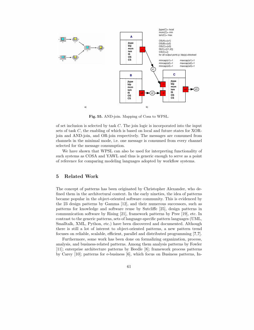
C
jtype blp mcm ism IS OS CS
A
i1
s1
jtype blp mcm ism IS OS CS
B
i2 s2
jtype blp mcm ism IS OS CS
o2
o1
jtype(C)= local mcm(C)= min ism(C)= max
OS(A)={o1} OS(B)={o2} OS(C)={o3} IS(C)={{i1,i2}} CS(C)={} for all output ports p: blp(p)=blocked
mincap(s1)=1 maxcap(s1)=1 mincap(s2)=1 maxcap(s2)=1 mincap(s3)=1 maxcap(s3)=1
a) b)
s3 o3
Fig. 55. AND-join. Mapping of Cosa to WPSL.
of set inclusion is selected by task C. The join logic is incorporated into the inputsets of task C, the enabling of which is based on local and future states for XOR-join and AND-join, and OR-join respectively. The messages are consumed fromchannels in the minimal mode, i.e. one message is consumed from every channelselected for the message consumption.
We have shown that WPSL can also be used for interpreting functionality ofsuch systems as COSA and YAWL and thus is generic enough to serve as a pointof reference for comparing modeling languages adopted by workflow systems.
5 Related Work
The concept of patterns has been originated by Christopher Alexander, who de-fined them in the architectural context. In the early nineties, the idea of patternsbecame popular in the object-oriented software community. This is evidenced bythe 23 design patterns by Gamma [12], and their numerous successors, such aspatterns for knowledge and software reuse by Sutcliffe [25], design patterns incommunication software by Rising [21], framework patterns by Pree [19], etc. Incontrast to the generic patterns, sets of language-specific pattern languages (UML,Smalltalk, XML, Python, etc.) have been discovered and documented. Althoughthere is still a lot of interest to object-oriented patterns, a new pattern trendfocuses on reliable, scalable, efficient, parallel and distributed programming [?,?].
Furthermore, some work has been done on formalizing organization, process,analysis, and business-related patterns. Among them analysis patterns by Fowler[11]; enterprise architecture patterns by Beedle [8]; framework process patternsby Carey [10]; patterns for e-business [6], which focus on Business patterns, In-
61
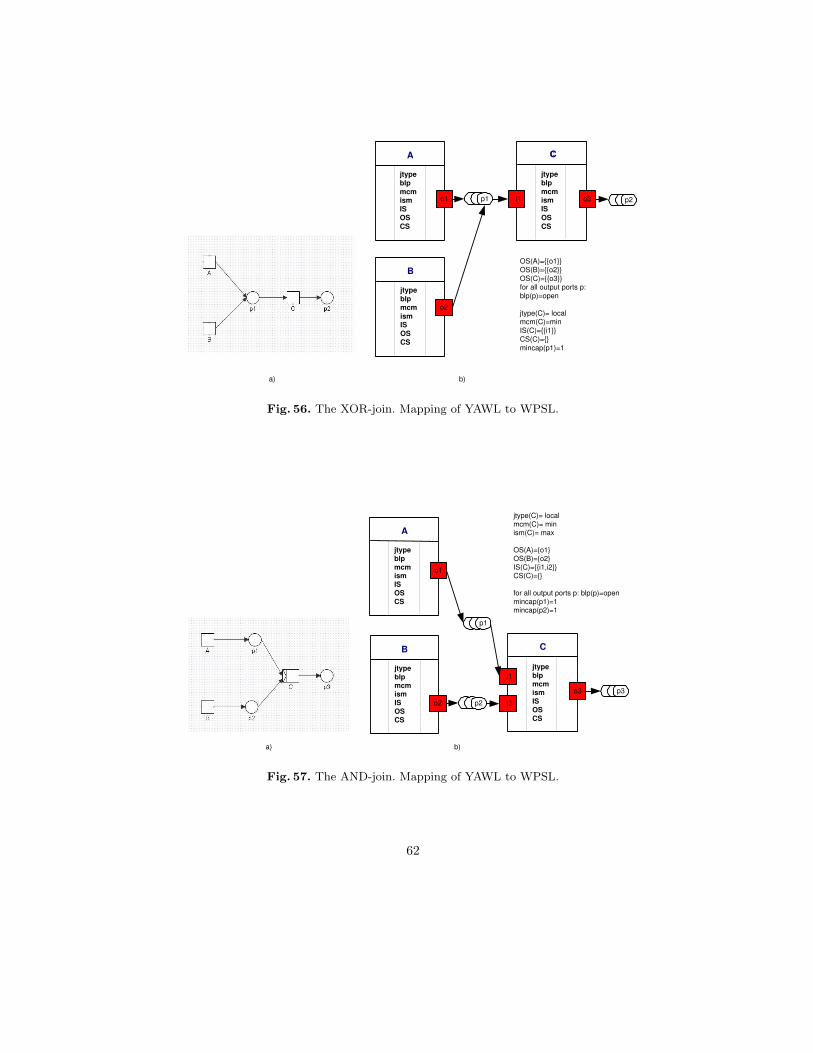
C C
jtype blp mcm ism IS OS CS
A
i1
jtype blp mcm ism IS OS CS
B
jtype blp mcm ism IS OS CS
o2
o1
OS(A)={{o1}} OS(B)={{o2}} OS(C)={{o3}} for all output ports p: blp(p)=open
jtype(C)= local mcm(C)=min IS(C)={{i1}} CS(C)={} mincap(p1)=1
p1 o3
p2
a) b)
Fig. 56. The XOR-join. Mapping of YAWL to WPSL.
C
jtype blp mcm ism IS OS CS
A
i1
jtype blp mcm ism IS OS CS
B
i2
jtype blp mcm ism IS OS CS
o2
o1
jtype(C)= local mcm(C)= min ism(C)= max
OS(A)={o1} OS(B)={o2} IS(C)={{i1,i2}} CS(C)={}
for all output ports p: blp(p)=open mincap(p1)=1 mincap(p2)=1
o3
p2
p1
p3
a) b)
Fig. 57. The AND-join. Mapping of YAWL to WPSL.
62

C
jtype blp mcm ism IS OS CS
A
i1
jtype blp mcm ism IS OS CS
B
i1
jtype blp mcm ism IS OS CS
o2
o1
jtype(C)= future mcm(C)= min ism(C)=max
IS(C)={{i1},{i2},{i1,i2}} OS(A)={{o1}} OS(B)={{o2}} OS(C)={{o3}} CS(C)={}
for all output ports p: blp(p)=open
o3 p3 p2
p1
a) b)
Fig. 58. The OR-join. Mapping of YAWL to WPSL.
tegration patterns, and Application patterns; and business patterns at work [25],which use UML to model a business system; process patterns [7].
The recent Workflow Patterns initiative [4] has taken an empirical approach toidentifying the most common control constructs inherent to modelling languagesadopted by workflow systems. In particular, a broad survey of modelling languagesresulted in 20 workflow patterns being identified [14]. The collection of patternswas originally limited to the control-flow perspective, thus the data, organizationaland application perspectives were missing. In addition, the set of control-flowpatterns was not complete since the patterns were gathered non-systematically:they were obtained as a result of an empirical analysis of the modelling facilitiesoffered by selected workflow systems.
The first shortcoming has been addressed by means of the systematic analysisof data and resource perspectives and resulted in the extension of the collectionof the control-flow patterns by 40 data patterns and 43 resource patterns [23, 22].The issue of the incompleteness of the control-flow patterns we have addressedin this paper and resolved it by means of the systematic analysis of the classicalcontrol-flow patterns against WPSL. Note that we are also working on revisingthe current set of the control-flow patterns and extending it with new patterns.
Our work is related to investigations into the expressive power and suitabil-ity of workflow languages, cf. [14]. Note that the term ”workflow patterns” hasbeen also addressed by other authors from a different perspective. In [26] a set ofworkflow patterns inspired by Language/Action theory specifically aiming at vir-tual communities was introduced. Patterns at the level of workflow architecturesrather than control flow were given in [17].
In [20] authors examined the suitability of pi-calculus for formalizing thecontrol-flow patterns. Such a formalization does not guarantee an unambiguousdescription of a pattern since the authors did not take into account the implicit
63

assumptions made in the original pattern definitions and thus analyzed specificinterpretations of the patterns excluding other interpretations.
Many workflow systems and standards such as XPDL, UML, BPEL, XLANG,WSFL, BPML, and WSCI were evaluated from the perspective of the classicalcontrol-flow patterns, a summary of which is available at [4]. Although multiplestandards have been proposed, none of them have become a common standard formodeling business processes. BPEL4WS 1.1 proved to be incomplete and weak,and has been gradually refined and extended. To increase the capabilities of BPEL,new accompanying standards are being proposed to extend BPEL capabilitiesin version 2.0 (BPELJ, BPEL4People, and BPEL-SPE). WS-BPEL 2.0 is beingconstantly revisited, examined and extended, and thus has not been finalizedso far. In this setting, WPSL could be utilized to evaluate the current BPELfunctionality, identifying strengthes and weaknesses, hence serving as a startingpoint for improvement.
6 Conclusions
In this paper, we introduced the Workflow Pattern Specification Language andused it as an evaluation strategy for comparing the process modelling languagesemployed by the workflow systems COSA, YAWL, Staffware, and Oracle BPELPM, to show that they interpret the same concepts differently while imposingsyntactic restrictions on their languages. Furthermore, we showed that ambigu-ous definitions of the control-flow patterns can be made more precise by the meansof setting the structural and behavioral properties of the basic process modellingentities in more detail. One of the immediate effects of doing this is the extensionof the pattern collection by pattern variants. The orthogonality of the dimensionsused for the classification of the basic modelling entities guarantees the complete-ness of the patterns within the scope of the identified dimensions.
The practical value of WPSL is multifaceted: it can be used as a means forexpressing the control-flow patterns more precisely, and as an analysis tool forcomparing the modelling languages adopted by various workflow systems. Fur-thermore, WPSL can be used by workflow systems developers to prevent themfrom imposing restrictive constraints on workflow specifications and it can helpin identifying which pattern variants a system needs to support.
In the light of the presented work, we plan to classify the various patternvariants identified by means of WPSL and develop a taxonomy for the control-flowpatterns. Further research is to be conducted into the identification of meaningfulcombinations of the patterns.
References
1. W.M.P. van der Aalst, A.P. Barros, A.H.M. ter Hofstede, and B. Kiepuszewski.Advanced Workflow Patterns. In O. Etzion and P. Scheuermann, editors, 7th In-ternational Conference on Cooperative Information Systems (CoopIS 2000), volume1901 of Lecture Notes in Computer Science, pages 18–29. Springer-Verlag, Berlin,2000.
64

2. W.M.P. van der Aalst, J. Desel, and E. Kindler. On the Semantics of EPCs: AVicious Circle. In M. Nuttgens and F.J. Rump, editors, Proceedings of the EPK 2002:Business Process Management using EPCs, pages 71–80, Trier, Germany, November2002. Gesellschaft fur Informatik, Bonn.
3. W.M.P. van der Aalst and A.H.M. ter Hofstede. YAWL: Yet Another WorkflowLanguage (Revised Version). QUT Technical report, FIT-TR-2003-04, QueenslandUniversity of Technology, Brisbane, 2003.
4. W.M.P. van der Aalst, A.H.M. ter Hofstede, B. Kiepuszewski, and A.P. Barros.Workflow Patterns Home Page. http://www.workflowpatterns.com.
5. W.M.P. van der Aalst, A.H.M. ter Hofstede, B. Kiepuszewski, and A.P. Barros.Workflow Patterns. Distributed and Parallel Databases, 14(1):5–51, 2003.
6. J. Adams, S. Koushik, G. Vasudeva, and G. Galambos. Patterns for e-Business. AStrategy for Use. IBM Press, 2001.
7. S.W. Ambler. Process Patterns. Cambridge University Press, 1998.8. M.A. Beedle. Enterprise Architecture Patterns. Cambridge University Press, 1998.9. BPEL. Wikipedia. The free encyclopedia. http://en.wikipedia.org/wiki/BPEL.
10. J. Carey and B. Carlson. Framework Process Patterns. Addison Wesley Longman,2001.
11. M. Fowler. Analysis Patterns: Reusable Object Models. Addison-Wesley, Reading,Massachusetts, 1997.
12. E. Gamma, R. Helm, R. Johnson, and J. Vlissides. Design Patterns: Elements ofReusable Object-Oriented Software. Professional Computing Series. Addison Wesley,Reading, MA, USA, 1995.
13. Object Management Group. OMG Unified Modeling Language, Version 1.4. OMG,http://www.omg.com/uml/, 2001.
14. B. Kiepuszewski. Expressiveness and Suitability of Languages for Control Flow Mod-elling in Workflows. PhD thesis, Queensland University of Technology, Brisbane,Australia, 2003. Available via http://www.workflowpatterns.com.
15. E. Kindler. On the Semantics of EPCs: A Framework for Resolving the ViciousCircle (Extended Abstract). In M. Nuttgens and F.J. Rump, editors, Proceedingsof the GI-Workshop EPK 2003: Business Process Management using EPCs, pages7–18, Bamberg, Germany, October 2003. Gesellschaft fur Informatik, Bonn.
16. E. Kindler. On the Semantics of EPCs: A Framework for Resolving the ViciousCircle. In J. Desel, B. Pernici, and M. Weske, editors, International Conferenceon Business Process Management (BPM 2004), volume 3080 of Lecture Notes inComputer Science, pages 82–97. Springer-Verlag, Berlin, 2004.
17. G. Meszaros and K. Brown. A Pattern Language for Workflow Systems. In Proceed-ings of the 4th Pattern Languages of Programming Conference, Washington Univer-sity Technical Report 97-34 (WUCS-97-34), 1997.
18. N.A. Mulyar. Pattern-based Evaluation of Oracle-BPEL (v.10.1.2). Technical report,Center Report BPM-05-24, BPMcenter.org, 2005.
19. W. Pree. Framework patterns. SIGS Books, 1996.20. F. Puhlmann and M. Weske. Using the pi-calculus for Formalizing Workflow Pat-
terns. In Proceedings of Business Process Management: 3rd International Confer-ence, Nancy, France, 2005.
21. L. Rising. Design Patterns in Communication Software. Cambridge UniversityPress, 2000.
22. N. Russell, A.H.M. ter Hofstede, D. Edmond, and W.M.P. van der Aalst. WorkflowData Patterns. QUT Technical report, FIT-TR-2004-01, Queensland University ofTechnology, Brisbane, 2004.
65

23. N. Russell, A.H.M. ter Hofstede, D. Edmond, and W.M.P. van der Aalst. WorkflowResource Patterns. BETA Working Paper Series, WP 127, Eindhoven University ofTechnology, Eindhoven, 2004.
24. Staffware. Workflow Patterns According to Staffware. Technical report. (Availablevia http://is.tm.tue.nl/research/patterns/download).
25. A. Sutcliffe. Patterns for Knowledge and Software Reuse. Lawrence Erlbaum Asso-ciates Inc., 2002.
26. H. Weigand, A. de Moor, and W.J. van den Heuvel. Supporting the Evolution ofWorkflow Patterns for Virtual Communities. Electronic Markets, 10(4):264–271,2000.
27. WFMC. Workflow reference model. Technical report, Workflow Management Coali-tion, Brussels, 1994.
28. WFMC. Workflow Management Coalition Workflow Standard: Workflow Pro-cess Definition Interface – XML Process Definition Language (XPDL) (WFMC-TC-1025). Technical report, Workflow Management Coalition, Lighthouse Point,Florida, USA, 2002.
29. M.T. Wynn, D. Edmond, W.M.P. van der Aalst, and A.H.M. ter Hofstede. Achievinga General, Formal and Decidable Approach to the OR-join in Workflow using Resetnets. QUT Technical report, FIT-TR-2004-02, Queensland University of Technology,Brisbane, 2004.
66