Embed Size (px)
Citation preview
Inter-noise 2014 Page 1 of 8
Towards a reduction of noise emission
of powered two-wheels - Part 2.
Michaël THIVANT; Christian CLERC1; David JAMIN; Quentin GAUTHIER2;
Joël LELONG; Roger CHATAGNON3 1 VIBRATEC SA – 28 Chemin du Petit Bois – 69130 ECULLY – FRANCE
2 PEUGEOT SCOOTERS – 103 Rue du 17 Novembre – 25350 MANDEURE – FRANCE 3 IFSTTAR/AME/LAE (Environmental Acoustics Laboratory), Université de Lyon, CeLyA,
25 av. François Mitterrand – Case 24 – 69675 BRON CEDEX - FRANCE
ABSTRACT
Transportation in urban areas is often synonymous of traffic congestion. In the last decade, this situation led users to give up passenger cars and incited them to adopt powered two-wheelers (PTW), better adapted to the traffic hazards. In the frame of the French research project Ascoot (Acoustique des scooters et des motorcycles), this paper focuses on the acoustic optimization performed on two scooters, including diagnosis and computation methodologies, leading to technical solutions implemented on 2 prototypes. The acoustic sources were located and quantified by acoustic imaging on roller benches, and the vibration behavior was characterized by means of experimental modal analysis (EMA) and measurement in operation. A simulation model was build for solutions design: excitation forces were derived from the measured combustion pressure and from a cinematic model of the engine moving parts, whereas structural dynamic response was computed by a Finite Element Model (correlated with EMA). An optimization of muffler design was also performed using transfer matrix models. The implementation of the noise reduction solutions on both prototypes is in progress; a minimum of 3dB noise abatement is expected. Keywords: Noise emission, powered two-wheels, Road traffic noise I-INCE Classification of Subjects Number(s): 52.3
1. INTRODUCTION In a context of strongest traffic congestion in urban areas, using powered two-wheelers,
particularly scooters, can be considered as an acceptable solution to avoid jammed traffic situations. However their noise emission must be controlled. French research project Ascoot (Acoustique des scooters et des motorcycles), aims at designing acoustic solutions for two scooters, Diagnosis and computation methodologies are briefly presented.
Page 2 of 8 Inter-noise 2014
Page 2 of 8 Inter-noise 2014
2. DIAGNOSIS
2.1 Acoustic Holography
An acoustic measurement campaign has been carried out on a roller bench, including 2 Peugeot scooters and 2 competitors. Predominant acoustic sources could be rapidly detected using a HDCam irregular antenna fitted with 36 microphones, and Irregular Nearfield Acoustical Holography treatment [1].
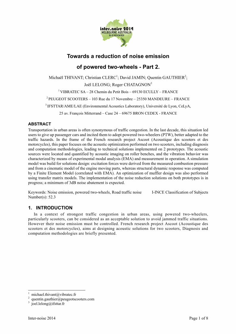
Figure 1 presents holograms on both sides of Peugeot 2 strokes scooter. The noise emission is
identified: • On the left side: either the transmission casing or the engine radiating through a chink • The cooling grid on the right side.
The frequency content of the noise radiated by the cooling grid includes both the turbine blades and the engine orders. Diagnosis was confirmed and refined during a second vibro-acoustic measurement campaign.
Figure 1 – Acoustic holography of 2 strokes 50cc scooter at 30km/h, full load.
Left/right side. Global A level
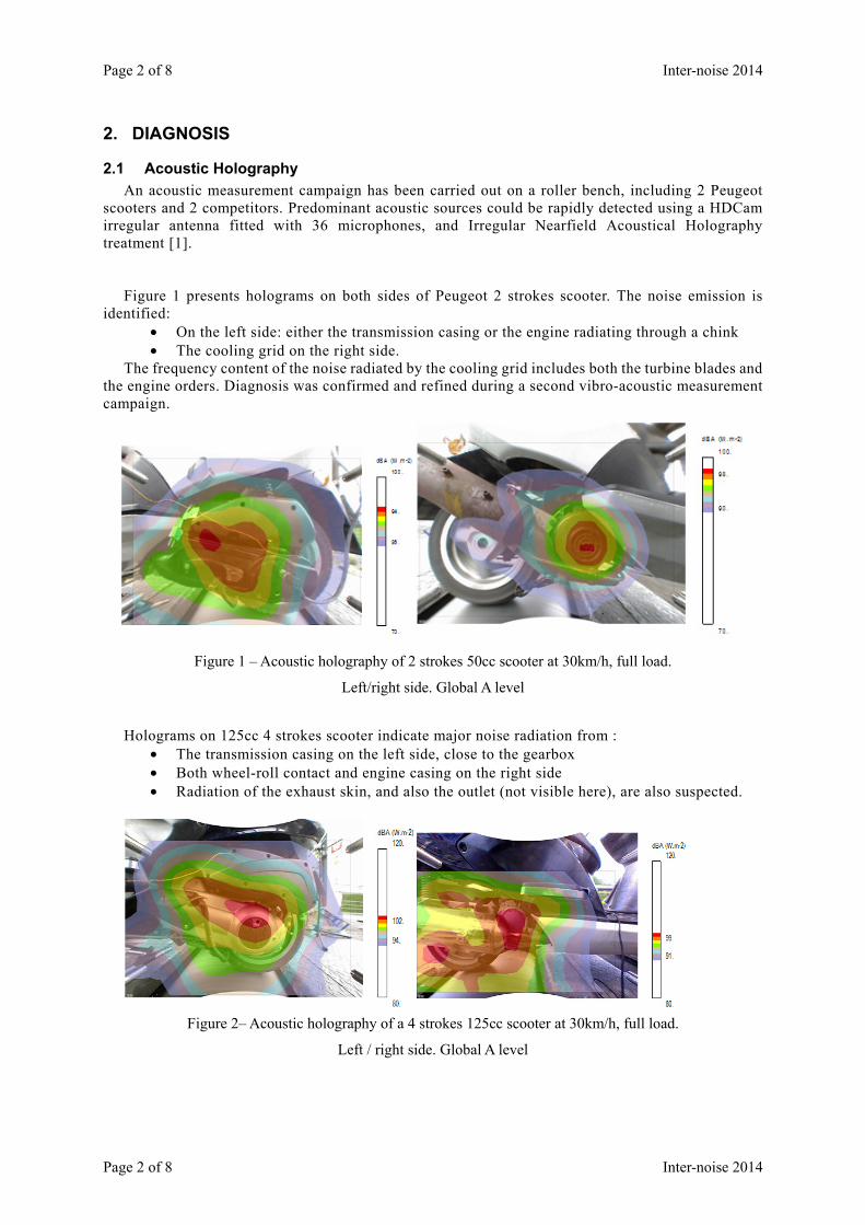
Holograms on 125cc 4 strokes scooter indicate major noise radiation from : • The transmission casing on the left side, close to the gearbox • Both wheel-roll contact and engine casing on the right side • Radiation of the exhaust skin, and also the outlet (not visible here), are also suspected.
Figure 2– Acoustic holography of a 4 strokes 125cc scooter at 30km/h, full load.
Left / right side. Global A level

Inter-noise 2014 Page 3 of 8
Inter-noise 2014 Page 3 of 8
2.2 Vibro-acoustic diagnostic
Acoustic holography helped focusing on predominant sources. But more insight on vibroacoustic phenomena is needed to design noise reduction solutions.
2.2.1 Operational measurements Acceleration on radiating sources was measured on a roller bench. On the 2 strokes 50cc scooter, the cooling fins are strongly vibrating, and happened to be the
predominant source, mostly responsible for the noise radiated through the cooling grid (Figure 3). Its low damped modal behavior is confirmed by vibro-acoustic transfer function measured with a
chock hammer and a response microphone in a semi-anechoic chamber (Figure 4). A stiffened cylinder casing has been tested, resulting in slightly higher resonance frequencies (pink curve), but still high response due to low damping (1%). Dampers and shields appeared to be more efficient solutions.
5000.000.00 Hz
ailette3:+X (CH50)
7700.00
6000.00
rpm
Tac
ho_m
ot (
T1)
-30.00
-90.00
dB(A
)
m/s
1.00
AutoPow er ailette3:+X (A) WF 234 [1834-7626.1 rpm] runup_ralenti+DA 1
Figure 3 Operational vibration on the cooling fins
5000.000.00 1000 2000 3000 4000500 1500 2500 3500 4500250 750 1250 1750 2250 2750 3250 3750 4250
Hz
0.20
20.0e-6
Log
Pa/
N
1.00
0.00
Am
plitu
de
278.33 4750.001504.001608.00
Curve 278.33 4750.00 RMS 1504.00 ζ (%) 1608.00 ζ (%) Hz
57.3e-6 6.48e-3 8.72e-3 651e-6 1.02 6.15e-3 0.10 Pa/N
71.6e-6 8.22e-3 9.48e-3 5.19e-3 0.12 752e-6 1.47 Pa/N
F FRF moy/Marteau FRF_moy_cart2F FRF moy/Marteau_pt1 FRF_moy
Figure 4 Vibro-acoustic transfer function of the cylinder casing
No specific high vibration level was found on the top of the transmission casing, nor on the intake filter, which indicates that the noise source might originate from the upper part of the engine.
Concerning the 125cc 4 strokes scooter, an additional pressure sensor was set in the combustion
chamber and analyzed in angular domain. The idea was to check the influence of the combustion pressure on vibration and noise, to derive forces transmitted via the bearing of the crankshaft, and to test several combustion parameters.

Page 4 of 8 Inter-noise 2014
Page 4 of 8 Inter-noise 2014
0 90 180 270 360 450 540 630 720-1 000 000
0
1 000 000
2 000 000
3 000 000
4 000 000
5 000 000
6 000 000
7 000 000
8 000 000Pression par cylindre
Angle vilebrequin(°)
Cylindre 1
Figure 5 Cylinder pressure (Pa) versus crankshaft angle
2.3 Loads on the engine block
A program has been developed to derive force tensor applied by the crankshaft on the engine block, based on the inertial characteristics of the mobile parts, the rotation speed and the measured combustion pressure. The theory can be found in the literature [2].
As expected for a mono-cylinder, the vertical force, essentially due to translation inertia, dominates over the transverse force, due to rotation inertia.
The roll torque is due to both combustion and rotation inertia, which slightly compensate each other.
Once expressed on bearings and cylinder liner and after a Fourier transform (Figure 8), the forces can be combined with either measured or computed transfer functions to compute their contributions to the vibration of the casing. Combustion forces are distributed over a wide range of harmonics, whereas vertical forces are concentrated on the first even orders.
Figure 6 – Interface of Vibratec program for the derivation of excitation tensor
Top dead center
Ignition
Connecting rod
Crankshaft
Bearings
Cylinder

Inter-noise 2014 Page 5 of 8
Inter-noise 2014 Page 5 of 8
0 90 180 270 360 450 540 630 720-1
-0.5
0
0.5
1x 10
4
Angle vilebrequin(°)
Fy
Fz
0 90 180 270 360 450 540 630 720-100
-50
0
50
100
150
200Couples totales
Angle vilebrequin(°)
Couple roulis total
Couple roulis inerties
Couple roulis combustionCouple galop
Couple lacet
Figure 7 Computed Forces and torques versus crankshaft angle
0 1 2 3 4 5 6 7 8 9 10 11 12 13 14 15 16 17 18 19 2010
-8
10-6
10-4
10-2
100
102
104
Ordre
Fy par palier
Fz par palier
Fy chemise
Figure 8 – Order spectrum of forces on crankshaft bearing and on cylinder liner
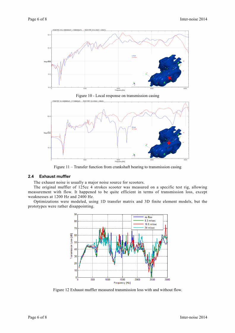
2.3.1 Experimental and numerical modal analysis An experimental modal analysis was performed on the engine and transmission casing. The
experimental setup is shown on Figure 9. Vibration transfer functions are compared to finite element results on Figure 10 and Figure 11. The
main features (resonance frequencies and order of magnitudes) are captured, although modeling contact stiffness and damping in casings assembly is rather tricky.
Figure 9 – Experimental modal analysis of the engine and casings of 125cc 4 strokes scooter
Fy on each bearing Fz on each bearing Fy on cylinder liner
Transverse forceVertical force
Total roll torque Inertial roll torque Comb. roll torque pitch torque yaw torque
Crankshaft Angle (degree)
Crankshaft Angle (degree)
Page 6 of 8 Inter-noise 2014
Page 6 of 8 Inter-noise 2014
0 1000 2000 3000 4000 1E-3
1E-2
1E-1
1E+0
1E+1
Frequency [Hz]
Magnitude
FEM FRF 213 (-1060404UY : +1060404UY) TEST FRF 213 (-33UY : +33UY)
Figure 10 - Local response on transmission casing
0 1000 2000 3000 4000
1E-2
1E-1
1E+0
Frequency [Hz]
Magnitude
FEM FRF 14 (+450683UZ : +1115862UZ) TEST FRF 14 (+23UZ : +36UZ)
Figure 11 – Transfer function from crankshaft bearing to transmission casing
2.4 Exhaust muffler
The exhaust noise is usually a major noise source for scooters. The original muffler of 125cc 4 strokes scooter was measured on a specific test rig, allowing
measurement with flow. It happened to be quite efficient in terms of transmission loss, except weaknesses at 1200 Hz and 2400 Hz.
Optimizations were modeled, using 1D transfer matrix and 3D finite element models, but the prototypes were rather disappointing.
Figure 12 Exhaust muffler measured transmission loss with and without flow.
Inter-noise 2014 Page 7 of 8
Inter-noise 2014 Page 7 of 8
3. NOISE REDUCTION SOLUTIONS
3.1 50cc 2-strokes scooter
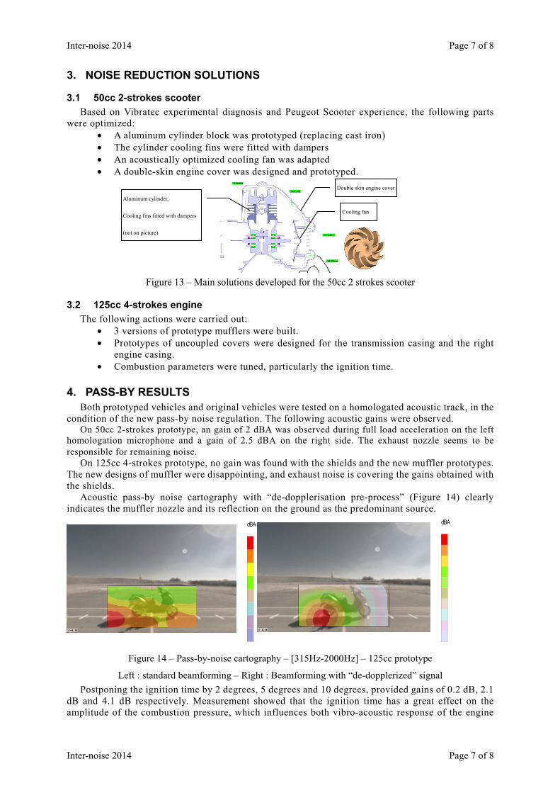
Based on Vibratec experimental diagnosis and Peugeot Scooter experience, the following parts were optimized:
• A aluminum cylinder block was prototyped (replacing cast iron) • The cylinder cooling fins were fitted with dampers • An acoustically optimized cooling fan was adapted • A double-skin engine cover was designed and prototyped.
Figure 13 – Main solutions developed for the 50cc 2 strokes scooter
3.2 125cc 4-strokes engine
The following actions were carried out: • 3 versions of prototype mufflers were built. • Prototypes of uncoupled covers were designed for the transmission casing and the right
engine casing. • Combustion parameters were tuned, particularly the ignition time.
4. PASS-BY RESULTS Both prototyped vehicles and original vehicles were tested on a homologated acoustic track, in the
condition of the new pass-by noise regulation. The following acoustic gains were observed. On 50cc 2-strokes prototype, an gain of 2 dBA was observed during full load acceleration on the left
homologation microphone and a gain of 2.5 dBA on the right side. The exhaust nozzle seems to be responsible for remaining noise.
On 125cc 4-strokes prototype, no gain was found with the shields and the new muffler prototypes. The new designs of muffler were disappointing, and exhaust noise is covering the gains obtained with the shields.
Acoustic pass-by noise cartography with “de-dopplerisation pre-process” (Figure 14) clearly indicates the muffler nozzle and its reflection on the ground as the predominant source.
dBA dBA (
Figure 14 – Pass-by-noise cartography – [315Hz-2000Hz] – 125cc prototype
Left : standard beamforming – Right : Beamforming with “de-dopplerized” signal
Postponing the ignition time by 2 degrees, 5 degrees and 10 degrees, provided gains of 0.2 dB, 2.1 dB and 4.1 dB respectively. Measurement showed that the ignition time has a great effect on the amplitude of the combustion pressure, which influences both vibro-acoustic response of the engine
Double skin engine cover
Cooling fan
Aluminum cylinder,
Cooling fins fitted with dampers
(not on picture)

Page 8 of 8 Inter-noise 2014
Page 8 of 8 Inter-noise 2014
block, and the acoustic source in the exhaust muffler. However this solution also affects the performance of the scooter in terms of acceleration and
maximal speed and especially, it highly raises the fuel consumption. Thus this solution is not really acceptable though it points out that there are probably linked solutions.
This is why Peugeot scooter is also working on alternative solutions, like decreasing the compression rate via geometrical changes, to reduce the maximal combustion pressure while keeping good mobility performances, which is a strong identity of the brand.
5. CONCLUSIONS A wide range of experimental and numerical techniques has been deployed to diagnose and
optimize the noise emission from scooters. Several solutions have been successfully tested in pass-by-noise conditions. However further optimization of the mufflers and combustion tuning are still needed to end-up with
really low-noise scooters.
ACKNOWLEDGEMENTS This work was performed within the framework of ASCOOT research project, supported by the
French Environment and Energy Management Agency (ADEME).
REFERENCES
1. Delescluse B, Thivant M. Caractérisation des véhicules Mesures de contributions, Report Ref. 562.035.RA.03.A, Projet ASCOOT Ecully, FRANCE. 2012.
2. Etat de l’art, bruit des deux-roues motorisés, livrable du lot1 du projet ASCOOT rapport ASCOOT-11R1L1, 61 p (2011).
3. Leclère Q., Polac L., Laulagnet B., Guyader J.L. Vibro-acoustique des moteurs d’automobile. In: Techniques de l’Ingénieur., FRANCE: 2009, 19 p.