Embed Size (px)
Citation preview

NASA Contractor Report 3852
Toughening Mechanism in Elastomer-Modified Epoxy Resins-Part 2
A. F. Yee and R. A. Pearson
CONTRACT NM1-16132 DECEMBER 1984
NASA
https://ntrs.nasa.gov/search.jsp?R=19850004738 2020-05-17T09:08:00+00:00Z

NASA Contractor Report 3852
Toughening Mechanism in Elastomer-Modified Epoxy Resins-Part 2
A. F. Y e e and R. A. Pearson
General Ekctric Company Scbenectady, N e w York
Prepared for Langley Research Center under Contract NAS 1-16 132
NASA National Aeronautics and Space Administration
Scientific and Technical Information Branch
1984

Sect ion P8ge
List of Illustrations ..................................... iv
List of Tables ............................................ vi
Summary ................................................... 1
1 Introduction .............................................. 3
2 Experimental Approach ..................................... 5
3 Materials ................................................. 8
4 Cross-Link Density Deformation ............................ 13
5 Fracture Toughness Results and Discussion ................. 18
6 Volume Dilation Results and Discussion .................... 21
7 Microscopy ................................................ 24
8 Dynamic Mechanical Studies ................................ 30
8.1 Experimental Techniques ............................... 30 8.2 Results and Discussion ................................ 32
9 Conclusions ............................................... 44
10 Acknowledgments ........................................... 46
References ................................................ 47
iii

LIST OF 1ILUmTIoNs
Figure 3-1:
Figure 3-2:
Figure 3-3:
Figure 3-4:
Figure 4-1:
Figure 5-1:
Figure 5-2:
Figure 5-3:
Figure 6-1:
Figure 6-2:
Figure 7-1:
Figure 7-2:
A schematic of the general chemical structure of the DGEBA epoxide monomers used in this investigation ..................................... 11
The effect of temperature on the complex viscosity on several solid epoxide resins used to determine cure temperatures ............... 12
The effect of monomer molecular weight on the glass transition temperatures of several DGEBA epoxies ..................................... 12
The glass transition temperature versus inverse epoxide monomer molecular weight that suggests a linear relationship ............................... 12
Shear modulus versus temperature measured in torsion to determine the molecular weight between cross-links ............................... 17
An illustrative plot of the data used to calculate the G of three plaques of DER667 /DDS / CI'BNffO%) .............................. 20
An illustrative plot of the magnitude of the slopes (GIc 1 determined in the fracture toughness measurements of this investigation ...... 20
Fracture toughness G versus epoxide monomer molecular weight of the neat resins and elastomer modified resins ......................... 20
IC
Tensile dilatometry results at a cross-head rate of 25.4 mm/s for the DER661IDDS epoxy and and the same epoxy modified with 10 vol% elastomer ........ 23
Tensile dilatometry results at a crosshead rate of 25.4 mm/s for the DER667/DDS epoxy and the same epoxy modified with 10 vol% elastomer ........ 23
An SEM micrograph of the fracture surface of the 332/DDS/13(10%) SEM specimen taken at the region where the pre-crack had been re-propagated ........ 27
An SEM micrograph of the fracture surface of the 661/DDS/13(10+) SEM specimen taken at the region where the pre-crack had been re-propagated (the beginning of the plastic zone) .................... 27
iv

Figure 7-3: An SEB micrograph of the fracture surface of the 667/DDS/13(10%) SEM specimen taken at the region where the pre-crack had been re-propagated (the beginning of the plastic zone) ............... 28
Figure 7-4: An optical micrograph, taken under cross-polarized light of the subsurface view of the plastic zone of a 332/DDS/13(10%) SEM specimen ............ 28
Figure 7-5: An optical micrograph, taken under cross-polarized light of the subsurface view of the plastic zone of a 661/DDS/13(10%) SEM specimen ............ 29
Figure 7-6: An optical micrograph, taken under cross-polarized light of the subsurface view of the plastic zone of a 667/DDS/13(10%) SEM specimen ............ 29
Figure 8-1: Dynamic Young's modulus at 1 Hz ( a ) DER667/DDS, (b) DER661/DDS, and (c) DER332/DDS ................ 39
Figure 8-2: Dynamic Poisson's ratio at 1 Hz ( a ) DER667/DDS, (b) DER661/DDS, and (c) DER332/DDS ................ 40
Figure 8-3: Dynamic shear modulus at 1 Hz calculated from E* and )* measurements. ( a ) DER667/DDS, (b) DER661/DDS and ( c ) DER332/DDS ................. 41
Figure 8-4: Dynamic bulk modulus at 1 Hz calculated from E* and )* measurements ( a ) DER667/DDS, (b) DER661IDDS, and (c) DER332/DDS ................ 42
Figure 8-5: Differential linear thermal expansion referenced to room temperature. Tine between temperature steps is 8-10 min. ( a ) DER667/DDS, (b) DER661/DDS, and (c) DER332/DDS ................................ 43
LIST OP TABLES
Table 3-1: Commercial Data of Epoxy Resins Given by Do# Chemical Company .............................. 10
Table 3-2: Epoxy Formulations Used in this Investigation ..... 10
Table 3-3: A Comparison of Calculated Values of n for Epoxy Monomers .................................... 11
Table 4-1: Molecular Weight Between Cross-Links . . . . . . . . . . . . . . 17
Table 5-1: A Comparison of Calculated and Measured Plastic Zones ...................................... 19
V

The r o l e of mat r ix d u c t i l i t y on the toughenabi l i ty and toughening mechan-
i s m of elastomer-modified DGEBA epoxies was inves t iga t ed . Matrix d u c t i l i t y
was v a r i e d by using epoxide r e s i n s of varying epoxide monomer molecular
weights . These epoxide r e s i n s were cured using 4 , 4 ' diaminodiphenyl su l fone
(DDS) and, i n some cases , modified with 10% HYCAR CTBN 1300x8. Frac ture
toughness values f o r the nea t epoxies were found t o be almost independent on
t he monomer molecular weight of the epoxide r e s i n used. However, i t was found
t h a t the f r a c t u r e toughness of t h e elastomer-modified epoxies was very depen-
dent upon the epoxide monomer molecular weight. Tens i l e d i la tomet ry ind ica t ed
t h a t t he toughening mechanism, when present , i s s i m i l a r t o the mechanism found
f o r t h e p ipe r id ine cured epoxies i n Par t 1. ' f ind ing .
R
SEM and OM corrobora te t h i s
Dynamic mechanical s t u d i e s were conducted t o shed l i g h t on the toughena-
b i l i t y of the epoxies. The time-dependent small s t r a i n behavior of these
epoxies were separated i n t o t h e i r bulk and shear components. The time-
dependent small s t r a i n behavior of these epoxies were separated i n t o the bulk
and shea r components. The bulk component i s r e l a t e d t o b r i t t l e f r a c t u r e ,
whereas, t he shear component is r e l a t ed t o y i e ld ing . It can be shown t h a t the
r a t e s of shear and bulk s t r a i n energy build-up, f o r a given s t r e s s a r e
uniquely determined by the values of Poisson's r a t i o , V . It was found t h a t V *
i n c r e a s e s as the monomer molecular weight of t h e epoxide r e s i n used increases .
This i nc rease i n V * can be assoc ia ted with the low temperature p r e l axa t ion .
The e f f e c t of increas ing cross- l ink dens i ty i s t o s h i f t the p r e l a x a t i o n t o
h ighe r temperatures and t o decrease the magnitude of t he j3 r e l axa t ion . Thus,
i n c r e a s i n g cross- l ink d e n s i t y decreases U* and inc reases the tendency towards
1

b r i t t l e fracture.
peaks i s b r i e f l y addressed.
The nature and origin of the low temperature r e l a x a t i o n
2

1. IHIpmumoN I
In our previous work (Part 111 the micromechanical mechanisms that con-
tribute to the toughness of elastomer-modified epoxies were investigated. For
a range of rubber particles from 0.1 to 10 p u in diameter, the deformation
mechanisms were found to be qualitatively similar. Furthermore, we deduced
that the role of the rubber particles in toughened epoxies was to cavitate
dissipating the bulk strain energy in the matrix and, in turn, promoting the
formation of shear bands in the matrix. Together, these two processes produce
a plastic zone ahead of the crack tip, which effectively blunts the sharp
crack and results in increased toughness. This deduction is in agreement with
those reached by Bascom and c o ~ o r l e r s ~ ’ ~ and is qualitatively similar to the
toughening mechanism in thermoplastics which do not readily craze.
However, not all epoxy resins can be toughened by elastomeric modifica-
4 tion. Meeks has shown that the toughness enhancement obtained by elastomeric
modification of epoxy resins is dependent on the structure of the curing
agent. This dependence may actually reflect varying degrees of cross-link
density.
ture toughness of neat epoxies decreases as cross-link density increases.
High cross-link density has been cited as the reason for the lack of toughness
enhancement in some elastomer-modified epoxies.
Several others5-* have come to similar conclusions: that the frac-
6
Since in our previous work we have identified the matrix as the major
energy absorbing component, it stands to reason that modifying the matrix may
lead to enhanced toughness. More specifically, the ability of the matrix to
form shear bands should be directly related to the amount of energy it can
dissipate, i.e., matrix toughenability. Furthermore, since ductility requires
3
large scale cooperative conformational rearrangements of the polymeric back-
bone, it is reasonable to expect that the reduction of cross-link density
should result in increased ductility. Consequently, the elastomer-modified
ductile epoxy can be expected to exhibit enhanced toughness.
The purpose of this work is to investigate the role of the matrix in the
deformation mechanisms of these complex materials. The use of trademarks or
names of manufacturers in this report does not constitute endorsement, either
expressed or implied, by the National Aeronautics and Space Administration.
4

In order to investigate the role of matrix ductility on the toughenabil-
ity of DGEBA epoxy resins, several plaques of varying cross-link densities
were produced. The control of cross-link density of these resins was obtained
by curing epoxide resins of varying molecular weights. l3 C NMR was performed
on the epoxy monomers to experimentally determine their average monomer molec-
ular weights. Differential Scanning Calorimetry, using a Perkin-Elmer DSC-IIA
and scanning at a rate of 10°C/min on ca. 10 mg samples, was performed to
determine the glass transition temperature of the cured epoxy plaques. The
glass transition temperature provided a qualitative assessment of cross-link
density.
In principle, the molecular weight between cross-links may be determined
using an equation from the theory of
Ge = B
9 rubber-el ast ic ity:
2 e r
r (7) v R T
0
where G is the equilibrium shear modulus in the rubbery region. e
v is the cross-link density,
R is the gas constant,
T is the absolute temperature,
g is a numerical factor approximately equal to 1,
r2 is the mean square end-to-end distance of the e
strands which are cross-linked,
r2 is the mean square end-to-end distance that 0
the same strands would assume if they are not cross-linked.
(1)

Since v = p/ , where P i s dens i ty and xnc i s the number-average nc
molecular weight between cross- l inksD then xnc can be e a s i l y determined from
2 e 2
r dynamic mechanical da t a using the following equation, assuming g = l and - = 1:
rO
- M nc G e
(2)
The dynamic mechanical d a t a were obtained wi th a Rheometrics Mechanical
Spectrometer equipped wi th a t o r s i o n a l f i x t u r e f o r s o l i d s . Shear moduli were
measured under o s c i l l a t i n g t o r s i o n a t 1Hz with s t r a i n amplitudes of 0.4 - 1.6%. Samples were heated i n a n i t rogen atmosphere i n five-degree s t e p s wi th
a five-minute dwell time, a t the end of which G ' , Gff and Tan 6 were de te r -
mined. The value, P, was est imated t o be 1.2 gfcm' from va lues given i n
Table 3.1.
The f r a c t u r e toughness of severa l nea t r e s i n s and elastomer-modified
r e s i n s were measured i n terms of the c r i t i c a l s t r a i n energy r e l e a s e r a t e Glc ,
which was determined using single-edge notched specimens (approximately 63.5mm
L x 12.7mm W x 6.lmm TI f r ac tu red i n three-point bending w i t h a span of
50.8mm. 10 , l l GIc was ca l cu la t ed using the fol lowing r e l a t i o n s h i p
U = GIc B D f
where U i s the s tored e l a s t i c energy,
B i s the specimen thickness ,
(3)
D i s the specimen width,
9 i s a func t ion r e l a t i n g the change i n compliance wi th c rack
1 eng t h . For each ma te r i a l , a t l e a s t s i x SEN specimens wi th varying crack l eng ths
were f r ac tu red on a screw d r iven I n s t r o n (Model 1125) a t a r a t e of 2.12 mmfs.
6

A Nico le t 2090 d i g i t a l osc i l loscope captured the load vs . time t r ace . The
average crack l eng th of each specimen was measured using an o p t i c a l micro-
scope. An AP-86 desktop computer was programmed t o i n t e g r a t e the load vs.
time t r a c e . In t h i s manner, the energy absorbed was ca l cu la t ed and, t oge the r
w i th the measured c rack l eng ths , the GIc was determined.
Deformation mechanisms were determined by a t e n s i l e d i la tomet ry technique
modeled a f t e r t h a t used by Bucknall" , except t h a t a cons tan t displacement
r a t e was used. The deforma-
t i o n mechanism of a ma te r i a l could then be ascer ta ined by analyzing the volume
s t r a i n vs . e longat iona l s t r a i n p lo t . In such p l o t s , i n i t i a l l y one t y p i c a l l y
sees an increase i n volume s t r a i n due t o t he Poisson ' s e f f e c t ; t h e r e a f t e r ,
deformational processes such as voiding r e s u l t i n a f u r t h e r increase i n the
volume s t r a i n , whereas shear deformation r e s u l t s i n a decrease i n t h e volume
s t r a i n . This decrease i s an a r t i f a c t of t h e technique and not n e c e s s a r i l y
r e a l b u t it i s very use fu l f o r s igna l ing the onset of shear banding processes
( s e e P a r t 1).
D e t a i l s of t h i s technique were given i n P a r t 1.l
1
To complement the volume s t r a i n data, f ractography was performed on the
SEN f r a c t u r e toughness specimens. This involved the ana lys i s of t he f r a c t u r e
su r face v i a Scanning E lec t ron Microscopy and of t he subsurface damage v i a
Transmission Opt ica l Microscopy. The major t o o l f o r SEM a n a l y s i s was an IS1
Super I1 Scanning E lec t ron Microscope. SEM specimens were coated w i t h a t h i n
f i l m of Au-Pd by spu t t e r ing .
t h i n s e c t i o n s of ma te r i a l removed from planes perpendicular t o the f r a c t u r e
su r face . These t h i n s e c t i o n s of f i lm were prepared by p o t t i n g f r a c t u r e d
specimens i n epoxy followed by thinning down wi th a po l i sh ing wheel.
of t h e s e techniques were given i n P a r t 1.
A Zei s s op t i ca l microscope was used t o examine
D e t a i l s
1
7

3. NATBPIALS
The mater ia l s used i n t h i s i n v e s t i g a t i o n cons is ted of s eve ra l DGEBA epox-
ide r e s i n s of varying epoxide equiva len t weights from Dow Chemical Company,
cured w i t h s to ich iometr ic amounts of 4,4'-diaminodiphenyl su l fone (DDS) from
the RSA Corp. The manufacturers da t a of t h e DGEBA epoxide r e s i n s a r e given i n
Table 3-1. These same r e s i n s were a l s o modified wi th Hycar CTBN 1300x13, a
l i q u i d copolymer of bu tad iene and a c r y l o n i t r i l e terminated wi th carboxyl end
groups kindly suppl ied by t h e B.F. Goodrich Chemical Company. A l l m a t e r i a l s
were used as received. Hycar CTBN 1300x13 was chosen as the e las tomer modif-
i e r s i n c e i t r e s u l t e d i n the formation of 1 - l o p rubber p a r t i c l e s upon curing.
S p e c i f i c formulations used i n t h i s i n v e s t i g a t i o n a r e presented i n Table 3-2.
The number of DGEBA r epea t u n i t s , n, ( s e e Figure 3-11, f o r t h e epoxide
The r a t i o of t h e a rea of t he s igna l monomers was determined using 1 3 C NMR.
from t e r t i a r y carbon on the BPA uni t versus the h a l f a rea of one of t h e epox-
ide carbon s igna l s i nd ica t ed t h e r a t i o of BPA u n i t s w i t h r e spec t t o the two
epoxide groups. Sub t rac t ing one from t h i s r a t i o g ives n. Table 3-3 compares
va lues of n ca lcu la t ed from manufacturer 's d a t a wi th the va lues of n deforming
using 1 3 C NMR.
t he conclusion t h a t t he monomer molecular weight was g r e a t e r than t h a t speci-
f i e d by t h e manufacturer and may account f o r excess DDS seen i n our cured
p l aques .
The l a r g e discrepancy i n n f o r t he DER664 r e s i n l eads us t o
Epoxy plaques were prepared a s follows: The epoxide r e s i n was placed i n
a g l a s s mixing j a r . I f a s o l i d r e s i n was used, t h e j a r w i th the r e s i n was
p laced i n an oven a t a temperature s u f f i c i e n t l y high t o melt and consol ida te
the r e s i n . For those specimens t h a t were elastomer-modified, t e n volume per-
8

cent of the CTBN was added. Then a stoichiometric amount of DDS was added.
This jar was immersed in a silicone bath for about 45-60 min. at ca.
above the typical cure temperature. This mixture was then mechanically
stirred for ca. 3 0 min. to dissolve the DDS, then degassed. The mixture was
poured into a mold that had been preheated at the cure temperature and cured
using one of three cure schedules.
2OoC
The curing schedule depends upon the molecular weight of the epoxide
monomers which possessed widely varying viscosities. These viscosities were
determined using a Rheometrics Mechanical Spectrometer. Figure 3.2 is a plot
of viscosity vs. temperature for several solid DGEBA epoxide resins. Since
these resins were poured into a Teflon-coated' mold, it was advantageous for
the viscosity of these resins to be less than 100 poise, which occurred at
about 20-25OC above the melting points for each of these resins.
information the following three cure schedules were employed:
With this
RES IN FIRST CURE POST CURE
DER332 337 12OoC for 16 hours 2OO0C for 2 hours
DER661 662 14OoC for 16 hours 2OO0C for 2 hours
DER664 667 16OoC for 16 hours 2OO0C for 2 hours
These curing schedules are modifications of those published by Lee and
N e ~ i 1 l e . l ~
than 20OoC.
A 25OoC post cure was required for DER332 since its T was greater 8
* Teflon is a registered trademark of E.I. duPont and Company.
9

TABLE 3-1
Commercial Data Of Epoxy Resins Given By Dow Chemical Company
SPG DGEBA Epoxide Equivalent Viscosity Resin Weight n* (Duran's MpOC) (g/ml)
DER332 172-176 (174) 0 40-50 poise 1.16
DER337 230-250(240) 0.42 viscous 1.16
DER661 475-575(525) 2.2 70-80°C 1.18
DER662 575-700(638) 3.0 80-90°C 1.18
DER664 87 5-975 ( 925 ) 4.8 95-105OC 1.18
DER667 1600-2000(1800) 10 115-130°C 1.18
MW-348 315 n calculated by n =
TABLE 3-2
Epoxy Formulations Used In This Investigation
Mass Mass When Modified Mass
Resin n Resin (g) DDS ( g ) CTBN (8)
DER3 3 2 0 500 189.3 60.3
DER3 3 7 .42 500 133.3 56.3
DER332/661 1.0 43.3/406.7 89.3 51.8
DER661 2.2 500 61.0 49.9
DER662 3.0 300 50.0 49.1
DER664 4.8 500 34.6 47.9
DER667 10 500 17.8 46.6
10

TABLE 3-3
A Comparison O f Calculated Values of n (n= The Number of DGEBA Repeat Units)
for Epoxy Monomers
Res i n n Calc. From n De rmined Avg. Monomer by “C NMR
Molecal ar Weights
332 0 0
661 2.2 2.8
664 4.8 5.7
667 10.2 10.6
0 0 / \
n
Figure 3-1. A schematic of the general chemical s t ruc ture of the DGEBA epox- ide monomers used i n t h i s i n v e s t i g a t i o n .
11

5 E
Figure 3-2. The e f f e c t of temperature Figure 3-3. The e f f e c t of monomer on the complex v i s c o s i t y molecular weight on the on several s o l i d epoxide g l a s s t r a n s i t i o n tempera- r e s i n s used t o determine t u r e s of several DGEBA c w e tempera t are s . e p o x i e s .
0 NEAT RESINS 0 ELASTOMER MOOIFIEO RESINS
2 510
0. OOE+OOO I . 50E-003
INVERSE MONOMER M W 3. DOE-003
Figure 3-4. The g l a s s t r a n s i t i o n temperature versus inverse epoxide monomer molecular weight that s u g g e s t s a l i n e a r r e l a t i o n s h i p .
12
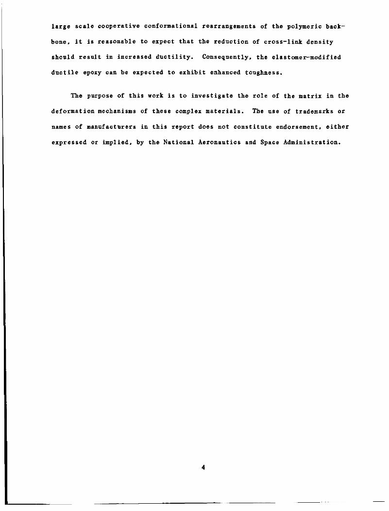
4. CBOSS-LINK DENSITY DETBWUUTICBIS
In a series of various monomer molecular weight epoxide resins cured with
the same curing agentD the glass transition temperature is a qualitative meas-
urement of the cross-link densityr i.e., the higher the cross-link density the
greater the glass transition temperature. The glass transition temperatures
of cured epoxy plaques were determined by DSC; the results are plotted against
molecular weight between cross-links in Figure 4-1. It is interesting to note
that the T initially decreases rapidly as the monomer molecular weight of the
epoxide resin is increased ( 2 2 O o C to 12OoC), but, at monomer molecular weights
greater than 1080 g/mole, the T only slightly decreases as the molecular
weight between cross-links is increased. A close examination of the litera-
ture reveals that several attempts have been made to relate the glass transi-
tion temperature to the cross-link density or the number average monomer
molecular weight between cross-links. Only two empirical approaches are
included in the following discussion.
8
g
The number average molecular weight between cross-links (g ) has been
empirically related to T by Nie1s0n.l~ He suggests that gc can be roughly
estimated by the use of the following relationship:
C
g
where T is the glass transition temperature of the uncross-linked polymer.
Nielson cautions that this equation only accounts for the effect of cross-link
restrictions on molecular motion and not for the so-called copolymer effect.
In the present caser our T data for the solid resin DER667 was found to be
lower than the melting point, which indicates that there may be some crystal-
BO
g
13

linity in the solid. This results in a negative T - T value of the B 80
uncross-linked DER667 resin. Consequently, this approach to relating cross-
link density to the glass transition temperature was abandoned.
Ellis and Banks" have used an empirical fit to the glass transition tem-
perature vs. the monomer molecular weight data for highly cross-linked DGEBA
epoxies with remarkable success. The following equation was used:
T = A + B x n -1 8
where A and B are constants. A is related to the T of an infinitely linear
polymer with the same repeat unit as the epoxies (The T of phenoxy resin is
373OC).
solely of the tetrafunctional cross-linking agent. A polymer of this type may
8
g
B may be related to the T of a highly cross-linked polymer composed g
degrade before ever reaching its T . This relationship is of a very general
form and has been used by Rietsch" to predict the effect of MW on the T of
linear and cross-linked polystyrenes.
8
g
Ellis and Banks" used a least squares fit of the glass transition tem-
peratures of several DGEBA resins cured with DDM (diaminodiphenyl methane) to
the inverse of the monomer molecular weight and determined that A=365 and
B=17300. Following this procedure, the glass transition temperature is plot-
ted against the inverse monomer molecular weight for DGEBA resins cured with
DDS (Figure 4-21. The least-squares fit gives A=354 and B=44000. The reason
for B being larger for the DDS cured DGEBA resins than the DDM cured resin may
be that DDS is a more rigid molecule.
As discussed previously in the experimental section, the molecular weight
between cross-links may be determined from the theory of rubber-elasticity.
This theory relates the equlibrium shear modulus to the molecular weight
14

between cross- l inks ( see Equation 2) . F igure 4-3 i s a p l o t of t h e s torage
shear moduli versus temperature f o r four DDS cured DGEBA epoxide r e s i n s of
varying monomer molecular weight. The equi l ibr ium shear modulus i s taken t o
be the va lue a t a temperature above T and we l l i n t o the rubber p l a t e a u where
i t approaches a constant . This t y p i c a l l y occurs a t 50 degrees above T . The
number average molecular weights between cross- l inks ca l cu la t ed using Equa-
t i o n s 1 and 2 a r e t abu la t ed i n Table 4-1. Note t h a t dens i ty = 1.2 g/cm , g = l
8
g
3
2
2 =1 and- =1 were used i n these ca lcu la t ions . The number-average molecular r
0
weights between cross- l inks a r e ca lcu la ted using t h e following equat ions:
- 2Me + Md M = nc 3
where Me i s the epoxide monomer molecular weight and,
Md i s the molecular weight of DDS (256 g/mole)
It i s important t o note t h a t the molecular weight between cross- l inks
i n c r e a s e s a s the molecular weight of the epoxy monomer i s increased. However,
t he experimental ly determined number-average molecular weight between cross-
l i n k s , M , a r e much higher than the values p red ic t ed from i d e a l
s t o i c h i o m e t r i c reac t ions . One reason f o r the g r e a t e r may be the presence
of e t h e r l inkages , a s Ochi e t a1.l' proposes. Bowever, t he preponderance of
evidence 15'18'19 p o i n t s t o e t h e r i f i c a t i o n as a very minor r e a c t i o n when p r i -
mary amine curing agents a r e used.
- nc
C
Takahama and Geil" a t t r i b u t e d the d i f f e r e n c e s between p red ic t ed cross-
l i n k d e n s i t i e s and experimental ly determined cross- l ink d e n s i t i e s using the
2 r, 1
rubber-plateau modulus t o changes i n the apparent f r o n t f a c t o r (-1 . These 2 r 0
15

authors found the same t rend as t h a t observed i n t h i s work, v i z . , as the
c ros s - l ink dens i ty decreased, t he measured cross- l ink d e n s i t y devia ted sys-
t e m a t i c a l l y by l a r g e r amounts from p red ic t ion . They reconci led t h i s
d i screpancy by assuming t h a t the apparent f r o n t f a c t o r changed from 0.84 t o
0.24. They, however, d id poin t out t h a t r u b b e r l i k e - e l a s t i c i t y theory may not
be appropr ia te f o r the d i func t iona l anhydride cured system used i n t h e i r work.
21 Katz and Tobolsky
seve ra l amine cured
have repor ted a f r o n t f a c t o r ranging
epoxies. Bonever, i n both cases the
from 0.78 t o 1.62 f o r
f r o n t f a c t o r s were
not experimental ly determined. In our c a l c u l a t i o n , we made no attempt t o vary
the apparent f r o n t f a c t o r i n order t o ob ta in b e t t e r agreement between the
experimental and the ca l cu la t ed r e s u l t s .
16

TABLE 4-1
Mol e c n l a r We i g h t Be twe en Cro s s-Link s
Monomer Mol e cu l a r
Weight G T M c a l c . Mnc c a l c . - -
Resin (g/mole) (dyne?cm2 1 ('9) f r o m v e (g/mole) from m . w . (g/mole)
DER332/DDS 334-3 52 1.3~10 546 420 317
DER661/DDS 950-1150 2.8~10 443 1600 7 85
8
7
DER664/DDS 1750-1950 1.97~10~ 428 2200 1319
DER667/DDS 3200-4000 7.0~10 423 6000 2485 6
1 . O E 6
60
0 +
x O ++ o o + + + * + + * + * +
0 0 0 0
x x
* x x x x
. 1 * + * + a +
120 1 eo 240 300
TEMPERATURE (dea C)
Figure 4-1. Shear modulus versus temperature measured i n t o r s i o n t o determine the molecular weight between cross - l inks .
17

5. FRACllJRE l W 6 " E S S RESULTS AND DISCUSSION
The energy pe r u n i t c ross -sec t iona l a rea (U/BD) f o r SEN specimens of
vary ing crack l eng ths f o r each ma te r i a l were p l o t t e d vs . P = dc/da and the
d a t a were f i t t e d t o a l i n e a r curve by the method of least-squares . The s lope
of t h i s l i n e is equal t o t h e G of the ma te r i a l . Figure 5-1 i s a p l o t of
U/BD vs . P for t h ree l o t s of DER667/DDS/13(109b). Figure 5-2 i l l u s t r a t e s the
l a r g e d i f f e rences i n the s lopes (G ' 9 ) of the elastomer modified r e s ins .
F igure 5-3 i s a p l o t of GIc versus the epoxide monomer molecular weight f o r
t he nea t r e s i n s as we l l a s t he elastomer modified r e s i n s . These r e s u l t s show
t h a t t he inherent f r a c t u r e toughness of t he nea t r e s i n s increases s l i g h t l y as
t he monomer molecular weight increases , while i n t h e rubber-modified s e r i e s
almost two orders of magnitude increase was seen. The nea t epoxy r e s i n s have
GIc va lues tha t a r e i n the same range as those repor ted by Sco t t , e t ~ 1 . ~ on
a l i p h a t i c amine cured epoxies and by Cherry and Thompson . In c o n t r a s t , the
f r a c t u r e toughness of t he elastomer-modified epoxies i s s t rong ly dependent
upon the molecular weight of the epoxide monomer. Therefore , t he toughenabil-
i t y of a DGEBA epoxy by elastomer-addi t ion depends upon the cross- l ink d e n s i t y
of t h e epoxy matrix. The lower the cross- l ink dens i ty , t he g r e a t e r the
toughenabi l i ty . This reduct ion i n cross- l ink d e n s i t y appears t o be the reason
f o r the toughness enhancement when BPA was added a s a r e s i n modi f ie r i n our
prev ious inves t iga t ion ( P a r t 1). This e f f e c t was a l s o observed by Riew
e t a l .
I C
I C
8
22
The toughening e f f e c t may be understood i n terms of t h e s i z e of t he p las -
t i c zone which b l u n t s t he sharp crack. According t o the Dugdale , t h e
s i z e of t h e p l a s t i c zone is inve r se ly p ropor t iona l t o the y i e l d s t r e s s . Thus,
any means tha t reduces the y i e l d s t r e s s should r e s u l t i n an increased p l a s t i c
1 8

zone and h igher toughness.
c u l a t e d p l a s t i c zone p c a l c
l a t e d p l a s t i c zone p
In Table 5-1 we have t abu la t ed the GIc , Q , ca l - Y
The calcu- and measured p l a s t i c zone pmeasured . i s the e f f ec t ive crack t i p r ad ius ca l cu la t ed using c a l c
The measured p l a s t i c zone pmeaSured was determined using
o p t i c a l microscopy. The measured p l a s t i c zones tend t o be l a r g e r than those
/ u . "talc = G I c y
ca l cu la t ed . Now the Q of these epoxies may be reduced by decreasing the
c ross - l ink dens i ty o r by the add i t ion of a rubber phase. However, the y i e l d
s t r e s s e s of DER 667 and DER 661 modified wi th 10% elastomer only d i f f e r by ca.
Y
lo%, whi le t h e i r shear and t e n s i l e moduli (no t shown) a re comparable. Thus,
the change i n toughness cannot be accounted f o r by the lower y i e l d s t r e s s
alone. Clear ly , an a n a l y s i s of t he micromechanical deformation i s needed t o
understand the energy processes providing toughness enhancement.
TABLE 5-1
A Comparison Of Calculated And Measured P l a s t i c Zones
Pme a sur e m x 10 -8 Pca1 cL6 Res i n G Q
Y (J/m 1 mPa m x 10 I "2
-- -- -- 332 162
661 201 96.1 2.1
667 326 85.6 3.8
332/ (13%) 242
661/ (13%) 3000 81.5 36 62
667/(13%) 11400 73.3 156 500
--
--
-- -- --
19

8000
6400
r\ rJ 4680 E '.
->
E1
-3
v
3208
1603
0
0. Om 8. 4 0 8. €38 1.20
PH 1
Figure 5-1. An illustrative plot of the data used to calculate the G of three plaques of DE&67/DDS/CTBN(lO%).
12000
10000
eo00
E \ C, 6000
u c2
v
w
4000
2000
0
"1
1 1 1 i i
c. c m a. 40 0. ec I. 20
PU I
Figure 5-2. An illustrative plot of the magnitude of the slopes (GIc ) determined in the fracture toughness measurements of this investigation.
/
, o/
200 1000 I eo0 2600 3400 4200
MONOMER MOLECULAR WEIGHT
Figure 5-3. Fracture toughness G IC versus epoxide monomer
molecular weight of the neat resins and elastomer modified resins.
20

6. VOLUME DILATICN RESULTS M D DISCUSSICN
Volume d i l a t i o n techniques have been used t o e l u c i d a t e the toughening
mechanisms i n thermoplas t ics . Bucknall12 has shown a l a r g e increase i n volume
s t r a i n when t e s t i n g high impact polystyrene and concluded t h a t c raz ing was t h e
major energy d i s s i p a t i o n mechanism.
be toughened by the a d d i t i o n of rubber. They used t h e volume s t r a i n technique
t o show t h a t the s lope of the volume s t r a i n curve decreased upon rubber modif-
i c a t i o n . They i n t e r p r e t e d these r e s u l t s t o mean t h a t a shear process i s
r e spons ib l e f o r the toughening e f f e c t . Maxwell and Yee24 used a volume d i l a -
t i o n technique t o determine t h a t crazing was a major energy consuming mechan-
i s m i n elastomer-modified polyphenylene oxide/polystyrene blends. The i r TEM
micrographs from deformed specimens provided conclusive evidence of c raz ing i n
these systems. This very same technique was used on piperidine-cured CTBN
Booley e t ~ 1 . ~ ~ has shown t h a t PMMA can
1 modified epoxies i n our previous repor t .
In t h i s study, volume d i l a t i o n experiments were aga in performed on two of
the nea t epoxies and t h e i r corresponding elastomer-modified ve r s ions t o e luc i -
d a t e t h e toughening mechanism(s1. These experiments a l s o provided s t r e s s vs.
s t r a i n da ta . In t h i s i n v e s t i g a t i o n , only the r e s u l t s a t 25.4mm/s crosshead
r a t e w i l l be examined s ince our previous work had shown t h a t a t t h i s r a t e the
deformation behavior of t he neat and elastomer-modified epoxies a r e more
c l e a r l y d i f f e r e n t i a t e d .
A t a crosshead r a t e of 25.4 mm/s and a t room temperature, dog bone speci-
mens of DER332/DDS f a i l e d i n a b r i t t l e mat te r . This ma te r i a l f a i l e d a t l e s s
than 1% s t r a i n and d id not e x h i b i t a y i e l d poin t . B r i t t l e f a i l u r e occurred
even when the DER332/DDS epoxy was modified wi th 10% HYCAR CX'BN 1300x8. The
21

volume s t r a i n increase seen i n these m a t e r i a l s was due s o l e l y t o the Poisson ' s
E f f e c t and thus gave no i n s i g h t i n t o the deformation mechanism(s). However,
a s t h e cross- l ink d e n s i t y of these epoxies a r e reduced they do e x h i b i t a y i e l d
p o i n t and the deformation mechanisms a r e d i sce rnab le by volume s t r a i n measure-
ment s.
Figure 6-1 is a p l o t of s t r e s s and volume s t r a i n versus long i tud ina l
s t r a i n f o r DER661/DDS and DER661/DDS/13(10%). Note t h a t these m a t e r i a l s exhi-
b i t e d y i e l d , and, a s expected, the incorpora t ion of rubber inc lus ions
decreased Young's Modulus and the y i e l d s t r e s s . The volume s t r a i n curve f o r
t he nea t r e s i n i n d i c a t e s t h a t t h i s ma te r i a l deforms by a shear process. How-
ever , the corresponding curve f o r the elastomer modified ma te r i a l i n d i c a t e s
t h a t a volume increas ing process i s superimposed on the shear process. Based
on our conclusions from P a r t 1, we can surmise t h a t t h i s volume increas ing
process i s most l i k e l y voiding. Thus, t he toughening mechanism f o r these
epoxies i s q u a l i t a t i v e l y s i m i l a r t o the p ipe r id ine cured epoxies s tud ied i n
P a r t 1.
Figure 6-2 is a p l o t of s t r e s s and volume s t r a i n versus s t r a i n f o r the
DER667/DDS mate r i a l s , the lowest cross- l ink d e n s i t y epoxies s tud ied i n t h i s
i nves t iga t ion . The volume s t r a i n curve f o r the neat r e s i n s exhib i ted the now
f a m i l i a r shear behavior. The volume s t r a i n curve f o r the elastomer-modified
v e r s i o n ind ica t e s t h a t t he voiding process i s a l s o present . These conclusions
a r e supported by microscopy, which i s descr ibed i n the next sec t ion .
22

I 1 I I I I I I I I 1
. > a
Figure 6-1. T e n s i l e
€1, %
di latometry r e s u l t s a t a cross-head r a t e of 2 5 . 4 mm/s f o r the DER661lDDS epoxy and and the same epoxy modif ied with 10 vol% e 1 a s tome r .
I I I I I I I I I I
EPOXY EQUIVALENT W E I G H T O F 1623-2333
103PSI
I6 - 667/DDS
- I I / / -
8 -
IC 1' 4-
-
0 I I I I 0 2 4 6 8 I
Epr %
Figure 6-2. T e n s i l e d i latometry r e s u l t s a t a crosshead
MPa I20
100
- 8 0
- 60
- 40
- 20
0
rate of 2 5 . 4 mmls f o r the DER667lDDS epoxy and the same epoxy modif ied with 10 vol% e l a s t ome r .
23

The SJBImicrographs of the fracture surfaces of three SEN specimens of
elastomer-modified epoxies of increasing monomer molecular weight (DER332,
DER661 and DER667 respectively) are shown in Figures 7-1, 7-2 and 7-3. For
the most highly cross-linked system (DER3321, the fracture surface (see Figure
7-1) contains very shallow and nearly hemispherical voids. This SEM micro-
graph was taken at the region of the specimen where the starter crack had been
arrested and then re-propagated during the three-point-bend test. This micro-
graph suggests that no plastic zone has been formed. The correlation between
the lack of toughness and the lack of a significant plastic zone will be dis-
cussed in the conclusion section.
In Figure 7-2, the SEM micrograph of the fracture surface of the DER661-
based epoxy, which is not as highly cross-linked as the DER332-based epoxy,
shows that the void regions are comparatively less hemispherical and are
deeper, which indicates that the rubber particles had cavitated and were then
subjected to a shear deformation. Note that there is no evidence of debond-
ing. This micrograph was taken in the region where the starter crack had
stopped and a stress-whitened or plastic zone had formed prior to unstable
fracture. The stress whitening results from the scattering of light by the
voided rubber particles. The formation of this plastic zone correlates well
with the toughening effect seen in this elastomer-modified epoxy.
The SEM micrograph (Figure 7-31 of the fracture surface of the elastomer-
modified epoxy, DER667, which is the least cross-linked epoxy studied in this
investigation, shows that the rubber particles have cavitated and been sheared
more severely as one progresses from the starter crack region into the stress-
24

whitened region. The length of t h i s zone extends from the a rea where the
s t a r t e r c rack i s a r r e s t e d t o the opposite edge of the SEN specimen. Also the
s i d e s of the specimen near the f r a c t u r e a r e concave, i nd ica t ing the onse t of
plane s t r e s s f r a c t u r e , which is another s ign t h a t the ma te r i a l is indeed
tougher. This mate r i a l exhib i ted the l a r g e s t p l a s t i c zone and the h ighes t G I C '
The na ture and ex ten t of t he sub-surface p l a s t i c zone formed ahead of t he
c rack t i p may be e luc ida ted by using t ransmission o p t i c a l microscopy. In our
prev ious work ( P a r t l ) ' we presented micrographs of t he sub-surface p l a s t i c
zone using b r i g h t f i e l d and cross-polar ized l i g h t . The b r i g h t f i e l d imaging
accen tua te s the c a v i t a t e d rubber p a r t i c l e s which, being e f f i c i e n t l i g h t
s c a t t e r e r s , appear almost black. The crossed-polarized l i g h t renders v i s i b l e
the shear bands which a r e composed of more h ighly o r i en ted ma te r i a l which i s
b i r e f r i n g e n t .
F igu re 7-4 i s an o p t i c a l micrograph of the ma te r i a l beneath the f r a c t u r e
su r face of t he elastomer-modified DDS-cured DER332 epoxy. The examined sec-
t i o n i s r a t h e r t h i c k (approximately 2 5 p ) bu t s t i l l no voided (dark) rubber
p a r t i c l e s a r e evident. Upon c lose examination, one may observe a small p las -
t i c zone of about one rubber p a r t i c l e diameter i n th ickness j u s t below the
f r a c t u r e surface.
F igu re 7-5 i s an o p t i c a l micrograph of a sub-surface view of the l e s s
h igh ly cross- l inked elastomer modified DER661 SEN specimen. Even under
c rossed po la r i zed l i g h t , t he cavi ta ted rubber p a r t i c l e s of t he p l a s t i c zone
can be seen. A s i g n i f i c a n t number of shear bands may be seen connecting these
voided rubber p a r t i c l e s . This region extends seve ra l t ens of microns beneath
the f r a c t u r e su r f ace.
25

Figure 7-6 is a o p t i c a l micrograph of the toughest e las tomer modified
epoxy t e s t e d i n t h i s study DER667/005/13(10%). The s i z e of t he p l a s t i c zone
i s enormous. A t t h i s magnif icat ion, t he e n t i r e zone cannot be contained i n
one micrograph. The s i z e of the c a v i t a t e d rubber p a r t i c l e s a r e l a r g e s t near
t he f r a c t u r e surface. The number of shear bands i s a l s o very s i g n i f i c a n t .
C lea r ly , t he formation of t h i s p l a s t i c zone must have consumed a s i g n i f i c a n t
amount of energy which r e s u l t s i n the high toughness.
26

Figure 7-1. An SEM micrograph of the f rac ture surface o f the 332/DDS/13(109b) SEM specimen taken a t the r e g i o n where the pre-crack had been re- propagated.
Figure 7-2. An SEM micrograph of the f rac ture surface of the 661/DDS/13(109b) SEM specimen taken a t the reg ion where the pre-crack had been re- propagated ( t h e beginning o f the p l a s t i c z o n e ) .
27

Figure 7-3. An SEM micrograph o f the f rac ture surface o f the 667/DDS/13(10%) SEM specimen taken a t the reg ion where the pre-crack had been re- propagated ( t h e beginning o f the p l a s t i c z o n e ) .
F igure 7-4. A n o p t i c a l micrograph, taken under cross -po lar ized l i g h t of the subsurface view of the p l a s t i c zone of a 332/DDS/13(10%) SEM specimen.
28

Figure 7-5 . An o p t i c a l micrograph, taken under cross -po lar ized l i g h t of the subsurface view of the p l a s t i c zone of a 661/DDS/13(109b) SEM specimen.
F igure 7-6. An o p t i c a l micrograph, taken under cross -po lar ized l i g h t o f the subsurface view of the p l a s t i c zone of a 667/DDS/13(109b) SEM specimen.
2 9

Dynamic mechanical studies were conducted to discover if in the neat
resins correlations exist between the viscoelastic behavior and their large
deformation behavior.
it is useful to separate the time-dependent small strain mechanical behavior
of polymers into their bulk and shear components. We postulated that while
the shear relaxation behavior is related to yielding its bulk counterpart is
related to brittle fracture, because the former type of deformation involves
shear flow whereas the latter dilatation.26
ness in elastomer-modified epoxies is found to be due mostly to the inherent
ability of the matrix to deform by shear banding, the role of the elastomer
particles being merely to reduce the constraints caused by the presence of a
crack so that the inherent potential of the matrix to undergo shear flow can
be unleashed. These findings are consistent with our thesis that studying the
bulk and shear viscoelastic behavior of the epoxies can shed light on their
toughenability.
In previous publications 2 5 B 2 6 we have pointed out that
In the present study, the tough-
8.1 Experimental Techniques
The dynamic bulk relaxation in a polymer is difficult to measure. Bow-
ever, by measuring the complex Young's modulus E*, and the complex Poisson's
Ratio V*, the complex bulk and shear moduli, i.e., K* and G*, can be calcu-
lated by using the simple viscoelastic relationship:
Notice that errors in the measured quantities are magnified in the calculated
quantities, especially in K* as l V * l approaches 0.5. Therefore, it is
30

e s s e n t i a l t o minimize systematic e r r o r s , We have avoided some of t he poss ib l e
sys temat ic e r r o r s i n temperature and frequency by measuring s imultaneously E*
and V*, t he b a s i c techniques f o r which have been descr ibed i n a previous
paper.25
t e s t i n g system.
desc r ibed i n b r i e f here.
Since our l a s t paper we have r e f ined the technique and automated the
The d e t a i l s of t h i s system a re given elsewhere2' and a re only
Dog-bone shaped specimens were cut from as-cast epoxy shee t s i n t o ASTM
D638 Type I specimens w i t h a th ickness of approximately 6mm. The ma te r i a l was
i s o t r o p i c in the plane. These specimens were t e s t e d i n an automated high
response servo-hydraul i c t e s t i n g machine2' ( I n s t r o n model 1350) i n load con-
t r o l wi th cons tan t mean load, i . e . , equal amplitude t ens ion and compression,
and w i t h cons tan t s t r a i n amplitude of 0.1%. The l a t t e r i s e s s e n t i a l f o r
ob ta in ing va lues of Poisson 's r a t i o tha t a r e not a f f e c t e d by changing s t r a i n
amplitude a s t he specimen compliance changes wi th temperature. The compres-
s i o n h a l f of the t e s t cycle i s f e a s i b l e because the s t r a i n i s q u i t e small , and
t h e specimen is q u i t e t h i c k and has been c a r e f u l l y a l igned. For the purpose
of t h e s e t e s t s only t h e f ixed frequency of 1 Hz was used. The temperature of
t h e specimen was monitored wi th a surface-mounted thin-f i lm type platinum
r e s i s t a n c e thermometer. This thermometer was in su la t ed from the surroundings
by s e v e r a l l a y e r s of PTFE tape. The i n i t i a l values of E* and V* were measured
t h r e e t o four times a t room temperature by s h i f t i n g the clip-on extensometers
around t o ensure good alignment, previous experience having ind ica t ed the
n e c e s s i t y f o r such a procedure. 25
c u l a t e t he average a t room temperature, and the f i n a l r e s u l t s were ad jus ted
accordingly. The specimens were cooled down from room temperature i n approxi-
mately 1 0 ° C s t e p s wi th 10-15 minutes between each s tep .
These i n i t i a l va lues were then used t o cal-
The v i s c o e l a s t i c
31

behavior was monitored throughout t he cool ing process . This r a t h e r slow cool-
ing process is necessary because volumetr ic thermal expansion and con t r ac t ion
a r e time-dependent processes , and thermal con t r ac t ion i s e s p e c i a l l y slow.
Thus, t he commonly used procedure of cool ing as r a p i d l y a s poss ib l e , u sua l ly
by enveloping the specimen wi th cold N2 gas o r l i q u i d and then taking d a t a
dur ing heat-up, can produce s u b s t a n t i a l e r r o r s i n the i n i t i a l heat-up por t ion .
Even the slow-cool procedure followed here i s not immune t o t h i s problem,
s i n c e the cont rac t ion r e l a x a t i o n times involved a r e orders of magnitude longer
than p r a c t i c a l l abo ra to ry time sca l e . In these t e s t s t he specimens were
cooled t o approximately -140'C from room temperature i n j u s t over t h ree hours.
The temperature was then kept constant a t t he minimum po in t f o r between 30 t o
60 minutes with the v i s c o e l a s t i c behavior monitored a t approximately 10 minute
i n t e r v a l s . When i t became c l e a r t h a t the measured q u a n t i t i e s were changing so
slowly as t o be unresolvable , then the heat-up run was begun. The heat-up run
was performed i n 5'C s t e p s , wi th about 10 minutes t o t a l allowed f o r each s t ep .
The temperature was measured before and a f t e r each ac tua l s e r i e s of da t a tak-
ing, and was found t o be cons tan t t o b e t t e r than 0 . 5 ' .
t he specimen was c y c l i c a l l y loaded f o r t en cyc les , and da ta were obtained on
the following t e n cyc les . The change i n l eng th of the specimen a t each tem-
p e r a t u r e was a l s o recorded. Thus, l i n e a r thermal expans iv i ty could be calcu-
A t a given temperature
l a t e d .
8.2 Results and Discussion
Resu l t s were obtained on-p on t h ree r e s i n s : DER667/DD , DER Cl/DDS, and
DER332/DDS. The r e s i n s wi th epoxide equiva len t weights in te rmedia te between
DER667 and DER661 were not t e s t e d because l i t t l e s i g n i f i c a n t v a r i a t i o n was
expected. These r e s u l t s a r e presented i n F igure 8-1 t o F igure 8-5. Figures
32

8-1 and 8-2 contain the experimentally obtained results on Young's moduli IE*I
and their associated loss tangents and Poisson's ratios lU*l and their associ-
ated phase angles, respectively. Figures 8-3 and 8-4 contain the calculated
results on the shear moduli IG.1 and their associated loss tangents, and the
bulk moduli lK* I and their associated loss tangents, respectively. Finally,
Figure 8-5 contains the results on the thermal expansion of the three resins.
Since the shear and bulk moduli are of primary concern, their behavior will be
discussed first.
The trends caused by increasing cross-link density are quite obvious in
the shear modulus. The glass transition temperatures are shifted systemati-
cally higher, in agreement with DSC and dynamic torsional measurements in the
T region. The sub-T shear moduli also increase with cross-link density.
This trend is intuitively obvious. The presence of the low temperature relax-
ation peaks lowers I G * I by about a factor of two.
compliance by the activation of supposedly local segmental mobility is impres-
sive, considering the fact that the maximum tan6 is only about 0.1. The low
temperature loss peak (at -72, -67, and -61OC) shifts systematically to higher
temperatures with increasing cross-link density. They also decrease slightly
in amplitude, and become broader. In DER332/DDS the width of this peak sug-
gests that the maximum at -61OC is actually composed of two peaks. In addi-
tion, there is a minor peak (in DER332/DDS) at 59OC.
a still lower temperature peak (<-12OoC) in all three resins.
g g
This enhancement of shear
There also appears to be
The magnitudes of the bulk moduli (Figure 8-4 a-c) of the three resins
exhibit an opposite trend from those of the shear moduli. The bulk moduli
actually decrease slightly with increasing cross-link density. Since bulk
modulus is the inverse of compressibility, we surmise that the higher cross-
33

link density actually produces a less closely packed structure, hence increas-
ing compressibility. The bulk moduli are also reduced by the occurrence of
the relaxations, albeit not to the same extent that the shear moduli are. The
error in the calculated bulk loss tends to be relatively large2’ , mostly
because of possible systematic errors in the phase angle of V*. We estimate
the systematic error in tan (6K) to be as much as fl x
nitude of uncertainty, the amplitude of the bulk losses can be considered to
be about the same. However, the shape and location of the bulk loss peaks are
relatively immune to systematic errors. Thus, it can be ascertained that the
bulk l o s s peaks occur generally at somewhat higher temperatures than their
shear counterparts, and that they are also shifted to higher temperatures with
increasing cross-linking. The latter shift is larger than that for the shear
peaks. These observations can be interpreted in the following manner. Bulk
relaxations necessarily involve highly correlated motional processes and are
affected by how strongly a relaxing species is coupled to its surroundings.
For the bulk effect to be so significant as to reduce the bulk modulus by some
409bD the relaxing molecular species must involve backbone moieties capable of
intermolecular motion. Its effect on thermal expansion (Figure 8-51, i.e.,
the onset of the motion causing a rapid increase in the volume, is further
evidence that the motion is strongly intermolecular. 28
increasing cross-link density shifts the bulk relaxation peak to systemati-
cally higher temperatures can be interpreted to mean that the intermolcular
mobility is being gradually reduced. This interpretation might appear intui-
tively obvious but for the fact that various other reseachers have offered
widely disparate interpretations on the nature of these peaks.
Some of these interpretations will be addressed in a later section.
Given this mag-
The fact that the
17,20,29,30

For the purpose of t he present discussion, s u f f i c e i t t o say t h a t what-
ever t he na ture and o r i g i n of these r e l axa t ion processes , they a r e being pro-
g r e s s i v e l y r e s t r i c t e d by increas ing the cross- l ink dens i ty . This r e s t r i c t i o n
i s observed i n both the bulk and shear components. How t h i s might a f f e c t t he
toughness of the r e s i n i s discussed i n t h i s sec t ion . For the d i scuss ion t o be
meaningful, i t i s necessary t o de f ine toughness. The terms " f r ac tu re tough-
ness'' and " d u c t i l i t y " a s used by var ious researchers i n t h e polymer community
both c a r r y d i f f e r e n t connotat ions. In the present contex t , f r a c t u r e toughness
i s a measure of t he t o t a l energy d i s s i p a t e d i n propagating a sharp crack
through a specimen s u f f i c i e n t l y t h i c k t o s a t i s f y the plane s t r a i n condi t ion,
and d u c t i l i t y i s a measure of t h e amount of p l a s t i c (non-recoverable) s t r a i n
t h e m a t e r i a l can s u s t a i n before f r a c t u r e occurs. Measurements of d u c t i l i t y
a r e gene ra l ly c a r r i e d out under s t a t e s of s t r e s s where the shear component i s
dominant, whereas measurements of f r a c t u r e toughness a r e c a r r i e d out under
s t a t e s of s t r e s s where the hydros t a t i c t e n s i l e component i s dominant. Under
the l a t t e r s t a t e of s t r e s s , inherent flaws i n the ma te r i a l can a c t as nuclea-
t i o n cen te r s f o r the formation of voids, which can then develop i n t o c razes o r
cracks. Thus, a given ma te r i a l can be both d u c t i l e and b r i t t l e depending on
t he s t a t e of s t r e s s . Generally speaking, shear s t r e s s l e a d s t o y i e l d i n g and
p l a s t i c flow, whereas hydros t a t i c tens ion l eads t o d i l a t a t i o n , void formation
and b r i t t l e f r a c t u r e . Thus, the b r i t t l e and d u c t i l e behavior a r e r e l a t a b l e t o
t h e bulk and shear compliance and d i s s ipa t ion . S p e c i f i c a l l y , shear y i e l d i s
due t o t h e accumulation of d i s t o r t i o n a l energy, a s evidenced by the wide-
a p p l i c a b i l i t y of the von Mises p l a s t i c y i e l d c r i t e r i o n i n polymers, and void-
ing i s due t o the build-up of bulk energy. Therefore , a t any given tempera-
t u r e and time sca l e , whether a mater ia l shear y i e l d s o r voids depends on the
r e l a t i v e r a t e s of shear and bulk energy build-up, d i s s i p a t i o n , and the
35

c r i t i c a l values f o r y i e ld ing and void formation. It can be shown t h a t the
r e l a t i v e r a t e s of shear and bulk energy build-up f o r a given s t r e s s s t a t e i s
uniquely determined by t h e value of t he Poisson ' s ra t io .31 A s V approaches
0 . 5 , t he bulk s t r a i n energy f o r any s t r e s s s t a t e not equal t o pure h y d r o s t a t i c
t e n s i o n i s extremely small compared t o shear s t r a i n energy. This i s the rea-
son why mater ia l s w i t h 9 approximately 0.5 a r e r a r e l y found t o f r a c t u r e b r i t -
t l e l y .
Now t ha t i t i s c l e a r t h a t V i s an index of t he r e l a t i v e r a t e s of accumu-
l a t i o n of bulk and shear energ ies , the deformation behavior of t he epoxies i n
t h i s s tudy can perhaps be b e t t e r understood. The behavior of the V* f o r t he
t h r e e d i f f e r e n t r e s i n s i s shown i n F igure 8-2. A t a l l temperatures, t h e
Poisson ' s r a t i o increases wi th increas ing molecular weight between cross-
l i n k s . Furthermore, t h e r e i s c l e a r l y an increase i n lU*l assoc ia ted wi th each
of t he low temperature r e l axa t ions . This increase s h i f t s t o higher tempera-
t u r e s w i t h increasing cross- l ink dens i ty . Following the reasoning ou t l ined i n
t h e l a s t paragraph, then, a t any given temperature, t he h igher the c ross - l ink
d e n s i t y , the more the tendency toward b r i t t l e f r a c t u r e . Now i t may be argued
t h a t t h i s trend i s , i n any case, i n t u i t i v e l y c l e a r . A more c r i t i c a l t e s t may
perhaps be an experiment t o l o c a t e d u c t i l e - t o - b r i t t l e t r a n s i t i o n temperatures ,
which i s beyond the scope of t he present i nves t iga t ion . S t i l l , t he r e s u l t s on
V a r e cons i s t en t wi th the f a c t t h a t the plane s t r a i n f r a c t u r e toughness of t h e
unmodified epoxies i s nea r ly independent of t he cross- l ink dens i ty , s ince i n
t h i s case the c o n t r o l l i n g f a c t o r i s the rap id build-up of bulk s t r a i n energy
dur ing the t e s t ; bu t , when rubber-modified, the toughness inc reases wi th
decreas ing cross- l ink dens i ty , s ince the bu lk - s t r a in energy i s d i s s i p a t e d by
the c a v i t a t i o n of the rubber and subsequent void growth, leav ing the bui l t -up

shear s t r a i n energy, which increases with V, t o cause ex tens ive formation of
shear bands. To put i t another way, the Poisson ' s r a t i o determines the
i n t r i n s i c manner t h a t s t r a i n energy i s p a r t i t i o n e d between d i l a t a t i v e and
shear modes. In plane s t r a i n f r a c t u r e , most of the s t r a i n energy i s a l ready
d i l a t a t i v e , so the small d i f f e r e n c e s i n V do not produce s i g n i f i c a n t d i f f e r -
ences i n the toughness. However, wi th the incorpora t ion of t h e rubber p a r t i -
c l e s , t h e i n t r i n s i c a b i l i t y of t he matrix t o deform i n the shear mode i s
unleashed.
We now b r i e f l y address the quest ion concerning the na tu re and the o r i g i n
of t h e low temperature r e l a x a t i o n peaks. This peak has been va r ious ly
ass igned t o the motion of t he hydroxyether group 12D20 , t he BPA unit2 ' , the
combination of hydroxyether and unspecif ied backbone motion17D30 , and so on.
Some of these assignments a r e based on comparisons wi th polymers w i t h s i m i l a r
molecular m ~ i e t i e s . ~ ' Others a r e based on modif ica t ions of t h e curing reac-
tion17'30 , degree of curel ' l , epoxide equiva len t weights2' , and subs t i t u -
t i o n s w i t h mon~epoxide .~ ' In one instance2' t h e t rend f o r the peak temperature
wi th r e spec t t o the cross- l ink dens i ty i s opposi te t o the f ind ings i n t h i s
work. The cause f o r t h i s discrepancy i s unclear. We note here t h a t the accu-
racy of dynamic mechanical measurements can be adversely a f f ec t ed by cool ing
and hea t ing too r a p i d l y and by using va r i ab le frequency. These negat ive fac-
t o r s have l a r g e l y been avoided i n the present i nves t iga t ion . As f o r t he
i n t e r p r e t a t i o n of dynamic-mechanical spec t ra , i t i s widely assumed t h a t not
only do va r ious molecular moie t ies possess ind iv idua l r e l a x a t i o n peaks, i n
much t h e same ray as, say, i n f r a r e d spectroscopy, bu t a l s o t h a t these peaks
a r e add i t ive . We should l i k e t o poin t out t h a t these assumptions a r e f r e -
quen t ly n o t co r rec t f o r t he simple reason t h a t molecular motions i n the s o l i d

are almost always strongly coupled to their surroundings. That this is true
is manifest in the fact that these relaxations are detectable by mechanical
spectroscopy and that they affect the compressibility as well as the thermal
expansion coefficient. The result of the strong coupling between the motion
of a part of the polymer molecule and its surroundings is that the incorpora-
tion of various modifications to the polymer is usually not simply an additive
effect but that it actually changes the structure of the polymer glass and the
entire relaxation spectrum. Thus, for example, if the cross-link density is
reduced by some means, the coupling between the relaxation species and their
surroundings is expected to be lessened, and the relaxation peak accordingly
shifts to lower temperature or shorter times. All these changes can occur
without changing the identity of the relaxing species. It is unnecessary to
postulate the appearance of new chemical species, as one would be wont to in
interpreting IR spectra.
The true identity of the relaxing species can be determined more unambi-
guously by incorporating substitutions on the benzene rings, which is beyond
the scope of the present investigation. Our best estimate is that the motion
involves the bisphenol as well as the hydroxyether groups, and that the range
of the motion extends over several BPA-hydroxyether units.

(a)
(b)
6 I.WE+E$- ffl
J 3
0 E
3 * t
a + LO 1.0E+0& W Z
0 >- 3 L
0 0
0 0 0
0
1.0E-01 j : I . BE-E2
i 1 . O E + O ~ u ~ I. 0E-03
-1FW -80 8 8 160 TEWERRTURE, d e g . C
I 6 1.0E+0& ffl 3 _1 3
0 E
1 r I
U 1 . E E + 0 4
Z 3 E >- O L
L
- 1.0E-01 i a
+
I. 0E-03 - IF0 -00 0 0 8 160
1.0E+0 ' I ' ' I ' ' ' I ' I ' I ' I ' ' ' I ' ' ' ' TEMPERRTURE, deg. C
_J 3
0 a
( C ) E
L1
- 1.0E-01 m +J
t- I .0E-E2
Figure 8-1. Dynamic Young's modulus at 1 Bz (a) DER667/DDS, (b) DER661/DDS, and ( c ) DER332/DDS.
39

(b)
c $ 3.2E-01b m cn t
0
i i
I
I .6E-01
1.2E-01
B.0E-02 : 0 a c
./ 7
4.3E-02 +
t i
4.0E-01 I .2E-01
f - "*a 0
.* 6 3.2E-01 *,e*
0
3.6E-01 E
ffl
ffl ffl H 0
0 i *-
H
a
2.4E-011 ' ' ' ' ' ' ' ' ' a I I 4 I ' 4 1 8 ' ' ' ' ' ' I -4 .0E-02 -160 -80 0 BE 160
TEMPERRTURE. d e g . C
1.6E-01 ' E-0 IF--
* / 4.0E-01
> 4 I . 2 E - 0 1
i 1
r" *a'"* a -" 4.0E-02
c
oo { 0.0E+00
Oo0- i
m
Z 0 3.2E-01 m ffl
0 a H
Figure 8-2. Dynamic P o i s s o n ' s r a t i o a t 1 Bz ( a ) DER667/DDS, (b) DER661/DDS, and ( c ) DER332/DDS.
40

( a )
(b)
,. j 1.0E-01 -1 m
+ 111 - n
a - Z
m n
* I U
II] 3
X I a
,. 1 . EE-81
m i-' - a, a Z
+
- a
I . QE-02
-160 -80 8 88 160 TEXPERi?TURF, d e g . C
Figure 8-3. Dynamic shear modulus at 1 Rz c a l c u l a t e d from E* and b* measure- ments. ( a ) DER667/DDS, (b) DER661/DDS and ( c ) DER332/DDS.
4 1

( a )
(b)
m a.
* Y
ffl
3 a 0 r
? - -- ! 0 -
I
I ' ' ' I '- I.0E-03 J , , ,opy , , , ,
I . EE+0 -160 -BE 0 E 8 160
TEMPERRTURE, deg. C
I "******".- ..- m i a. ; I.EE+E+ Y
ffl 3
r
i
- 0
i
1
1 1
Figure 8-4. Dynamic b a l k modulus a t 1 Bz c a l c u l a t e d from E* and V* measure- ments ( a ) DER667/DDS, ( b ) DER661/DDS, and ( c ) DER332/DDS.
42

TEMPERRTURE, d e g . C
Figure 8-5. D i f f e r e n t i a l l i n e a r thermal expansion referenced t o room tempera- ture. Time between temperature s t e p s i s 8-10 min. ( a ) DER667/DDS, (b ) DER661/DDS, and ( c ) DER332/DDS.
43
-

9. coNcLus1oNs
In our previous investigation (Partl)' , we deduced that toughness
enhancement by elastomer modification was principally due to two energy dissi-
pation mechanisms occurring at the crack tip. The first mechanism dissipates
bulk strain energy via cavitation of the rubber particles. The second mechan-
ism dissipates shear strain energy by enhancing the formation of shear bands
by the voided rubber particles. In this investigation, it was found that a
large decrease in cross-link density of neat DGEBA epoxies cured with DDS pro-
duced only a modest increase in fracture toughness, and simple elastomeric
modification of these epoxies did not guarantee enhanced toughness. However,
the toughenability was found to be a strong function of the inherent matrix
ductility, which is a function of cross-link density. The micromechanical
mechanisms, voiding and enhanced shear band formation, are again the energy
dissipation processes .
It can be argued that the increase in toughenability originates from
increased ductility which is due to a lowering of the glass-transition tem-
perature. Bowever, high glass transition temperatures do not necessarily
correspond to brittleness; in fact, many high T polymers are very ductile
when tested in uniaxial tension at room temperature. We contend that as long
as the matrix is ductile, then it can be toughened by the addition of a rub-
bery phase.
B
The results of the dynamic bulk and shear relaxation studies show that
the shear modulus increases while the bulk modulus decreases with cross-link
density. Low temperature relaxation peaks also exist in the bulk mode. The
small relative shifts in the positions of the bulk and shear peaks with cross-

l i n k d e n s i t y r e s u l t i n turn i n s h i f t s of low-to-high Po i s son’s r a t i o trans i -
t i o n s . This l a t t e r s h i f t may exp la in why shear mode deformation becomes pro-
g r e s s i v e l y more d i f f i c u l t a s the cross- l ink d e n s i t y increases .
45

10. A U N W B Y E N T S
The authors wish to thank Dr. N. Johnston of NASA-Langley, the Contract
Monitor of this work, for his encouragement and patience.
The authors also wish to acknowledge the assistance of the following
scientists at General Electric Corporate Research and Development: Mr. J .
Grande for performing the optical microscopy work; Dr. M.T. Takemori, Dr. D.S.
Matsumoto, Mr. T.A. Yorelli and Ms. L.M. Carapellucci for stimulating discus-
sions; Dr. A . R . Shultz and Mrs. A.L. Young for their assistance with the DSC
T measurements; Dr. E.A. Williams for the 13C NMR work; and Drs. S.Y. Hobbs
and P.C. Juliano for their support. B
46

1. A.F. Yee and R.A. Pearson, "Toughening Mechanism in Elastomer-Modified
Epoxy Resins - Part l", NASA Contractor Report 3718 (August 1983).
2. W.D. Bascom, R.L. Cottington, R.L. Jones, and P. Peyser, "The Fracture of
Epoxy and Elastomer Modified Epoxy Polymers in Bulk and As Adhesives", J.
Appl. Polym. Sci., 19, 2425 (1975).
3. W.D. Bascom and R.L. Cottington, "Effect of Temperature on the Adhesive
Fracture Behavior of an Elastomer" J. Adhesion, 1, 333 (1976).
4. C. Meeks, "Fracture and Mechanical Properties of Epoxy Resins and Rubber-
Modified Epoxy Resins", Polymer, 15, 675 (1974).
5. T.D. Chang, and J.O. Brittain, "Studies of Epoxy Resins Systems Part D:
Fracture Toughness of an Epoxy Resin: A Study of the Effect of Cross-
Linking and Sub-T Annealing" Poly. Eng. and Sci., 22, 1228 (1982). 8
6. J.N. Sultan, R.C. Laible, and F.J. YcGarry "Microstructure of Two-Phase
Polymers", Appl. Poly. Symp., 16, 127 (1971).
7. B.W. Cherry and K.W. Thompson, "The Fracture of Highly Cross-Linked Poly-
mers", J. Mater. Sci., s, 1913 (1981).
8. J.M. Scott, G.M. Wells and D.C. Phillips, "Low Temperature Crack Propaga-
tion in an Epoxide Resin", J. Mater. Sci., 15, 1436 (1980).
9. J.D. Ferry, "Viscoelastic Properties of Polymers", 3rd ed., John Wiley
Sons, Inc., New York, 1980.
47

10. E. Plati and J.G. Williams, "The Determination of the Fracture Parameters
for Polymers in Impact", Poly. Eng. Sci., 15, 470 (1975).
11. P.E. Reed, "Impact Performance Of Polymers" in Developments in Polymer
Fractare-1, Applied Science Publishers, pp 121-152 (1977).
12. C.B. Bucknall, "Toughened Plastics", Applied Science, London, 1977.
13. H. Lee and K. Neville, "Handbook of Epoxy Resins", McGraw-Hill Book C O O ,
New Pork, 1967.
14. L.E. Nielson, "Effects of Cross-Linking On The Glass Transitionsf', J.
Macromol. Sci., Rev. Macromol. Chem., Q(&), 77 (1969).
15. L. Banks and B. Ellis, "The Glass Transition Temperatures of Highly
Cross-Linked Epoxy Networks: Cured Epoxy Resins", Polymer, 23, 1466
(1982).
16. H.F. Rietsch, "Statistical Thermodynamic Treatment of Glass Transition
for Cross-Linked Polymers of Varying Functionality", Macromolecules, 11,
477 (1978).
17. M. Ochi, M. Okazaki and M. Shimbo, "Mechanical Relaxation Mechanism of
Epoxide Resins Cured With Alphatic Diamines", J. Poly. Sci.: Poly. Phys.
Ed., 20, 689 (1982).
18. J.P. Bell, ffStructore of a Typical Amine-Cured Epoxy Resin", J. Poly.
Sci. Part A-2, 6, 417 (1970).
19. L. Buckley and D. Roylance, "Kinetics of a Sterically Hindered Amine-
Cured Epoxy System", Poly. Eng. Sci., =, 166 (1982).
48

20. T. Takahama and P.H. Geil, "Dynamic Mechanical Properties of Epoxy
Resins", J. Poly. Sci.: Poly. Letters Ed., 20, 453 (1982).
21. D. Katz and A.V. Tobolsky, "Rubber Elasticity in a Highly Cross-Linked
System", Polymer, 4, 417 (1963).
22. C.K. Riew, E.B. Rowe and A.R. Siebert, in "Advances in Chemistry Series,
No. 154, Toughness and Brittleness of Plastics", American Chemical
Society, 326 (1976).
23. C.T. Hooley, D.R. Moore, M. Whale and M.J. Williams, "Fracture Toughness
of Rubber Modified PMMA", Plastics and Rubber Processing and Applica-
tions, 1, 345 (1981).
24. M.A. Maxwell and A.F. Yee, "The Effect of Strain Rate on the Toughening
Mechanisms of Rubber-Modified Plastics", Poly. Eng. and Sci., 21, 205
(1981).
25. A.F. Yee and M.T. Takemori, "Dynamic Bulk and Shear Relaxation in Glassy
Polymers. I. Experimental Techniques and Results on PMMA". J. Poly.
Sci.: Poly. Phys. Ed., 20, 205 (1982).
26. A.F. Yee, "Dynamic Bulk and Shear Relaxations in Solid Polymers: Rela-
tionship to Deformation Behavior". Proc. 5th Int. Conf. Deformation,
Yield and Fracture Of Polymers, 1982, Cambridge.
27. A.F. Yee, "Dynamic Mechanical Analysis of Practical Plastic Specimens
Using an Automated Servo-hydralic Tester", Proc. SPE ANTEC (Chicago), 29,
538 (1983).
49

28. J.M. Roe and R. Simha, "Thermal Expansivity and Relaxational Behavior of
Amorphous Polymers at Low Temperatures", Inter. J. Poly. Mater., 3, 193
(1974).
29. E. Cuddihy and J. Moacanin, "Dynamic Mechanical Properties of Epoxides b-
Transition Mechanism", p. 96 in "Epoxy Resins", R.F. Gould, ed., #92 in
Adv. Chem. Ser., ACS, 1970.
30. J.G. Williams, "The Beta Relaxation in Epoxy Resin-Based Networks", J.
App. Poly. Sci., 23, 3433 (1979).
31. J.G. Williams, "Stress Analysis of Polymers", J. Wiley and Sons, New
York, 1973, p. 49.
32. A.J. Kinloch and J.G. Williams, "Crack Blunting Mechanisms in Polymers",
J. Mater. Sci., 15, 978 (1980).
50

1. Report No. NASA CR-3852
I
15. Supplementary Notes
2. Government Accession No. 3. Recipient's Catalog No.
4. Title and Subtitle
TOUGHENING MECHANISM I N ELASTOMER-MODIFIED EPOXY RESINS-PART 2
7. Author(s)
A. F. Y e e and R. A. Pearson
9. Performing Organization Name and Address
General E l e c t r i c Company Corporate R&D Center P.O. Box 8 Schenectady, NY 12301
12. Sponsoring Agency Name and Address
National Aeronautics and Space Administration Washington, DC 20546
~
Dynamic mechanical p r o p e r t i e s Cro s s- 1 ink dens i t Y I
5. Report Date
December 1984 6. Performing Organization Code
8. Performing Organization Report No. 84-SRD-0 4 1
10. Work Unit No.
11. Contract or Grant No.
NAS1-16132 13. Type of Report and Period Covered Contractor Report J u l y 1, 1982-Aug. 30, 198 14. Sponsoring Agency code
Subject Category 2 7
17. Key Words (Suggested by Author(s))
EPOXY Rubber-modified epoxy Impact F r a c t u r e toughness Epoxy mechanical p r o p e r t i e s Polymer mechanical p r o p e r t i e s
19. Security arssif. (of this report) 20. Security Classif. (of this page) 21. No. of Pages 22. Rice
18. Distribution Statement Unclass i f ied - Unlimited
I Unclass i f ied I Unclassif ied I 56 I A04
For sale by the National Technical Information Service. Springfield. Virginla 22161 NASA-Langley, 1984

![EPOXY RESINS - Krishna districtkrishna.nic.in/PDFfiles/MSME/Chemical/EPOXY RESINS[1].pdf · EPOXY RESINS CONTENTS SECTION I ... PROJECT COST AND PROFITABILITY PROJECTIONS ... Epoxy](https://img.dokumen.tips/doc/110x75/5aa5b17b7f8b9ab4788d7c0f/epoxy-resins-krishna-resins1pdfepoxy-resins-contents-section-i-project.jpg)