Embed Size (px)
Citation preview
TOUCHLESS FINGERPRINT RECOGNITION
SYSTEM
M.TECH RnD REPORT
By
MEET HARESH HARIA
(153079029)
Under the guidance of
PROF. VIKRAM M. GADRE
Department Of Electrical Engineering
INDIAN INSTITUTE OF TECHNOLOGY BOMBAY

i
Contents
1. INTRODUCTION: ....................................................................................................................... 1
2. FINGERPRINT IMAGE PRE-PROCESSING: ........................................................................ 3
1) FINGERPRINT IMAGE SEGMENTATION: ....................................................................................... 3
2) GREY-LEVEL VALUE NORMALISATION ....................................................................................... 4
3) ESTIMATION OF A RIDGE PIXEL ORIENTATION ............................................................................ 5
4) ESTIMATION OF RIDGE FREQUENCY ........................................................................................... 7
5) GABOR FILTERING ...................................................................................................................... 8
6) BINARISATION AND THINNING .................................................................................................. 10
3. EXTRACTION OF MINUTIAE AND REMOVAL OF FALSE MINUTIAE: .................... 12
4. MINUTIA EXTRACTION ALGORITHM: ............................................................................ 13
5. FINGERPRINT MATCHING: ................................................................................................. 14
ELASTIC MINUTIAE MATCHING ALGORITHM: .................................................................................. 14
Local Matching ............................................................................................................................. 14
Global Matching ........................................................................................................................... 15
6. ANDROID APP IMPLEMENTATION .................................................................................... 16
7. TOUCHLESS FINGERPRINT APP DESCRIPTION: .......................................................... 17
1) CAMERA .................................................................................................................................... 17
i) Enrol ..................................................................................................................................... 17
ii) Verify ..................................................................................................................................... 19
iii) Identify .................................................................................................................................. 19
2) GALLERY ................................................................................................................................... 20
i) Enrol ..................................................................................................................................... 20
ii) Verify ..................................................................................................................................... 21
iii) Identify .................................................................................................................................. 21
3) SCANNER ................................................................................................................................... 22
i) Verify ...................................... 22
ii) Identify ................................... 23
8. WEB SERVER AND DATABASE ............................................................................................ 24
9. MOBILE-SERVER COMMUNICATION: HTTP URL CONNECTION ............................ 25
10. JAVA SOCKET COMMUNICATION .................................................................................... 26
11. SOURCEAFIS LIBRARIES ...................................................................................................... 27
12. CONCLUSION AND FUTURE WORK .................................................................................. 28
13. REFERENCES ............................................................................................................................ 29

ii
Figures
FIGURE 1: FINGERPRINT PATTERN – ARCH, LOOP, WHORL ......................................................... 1
FIGURE 2: MINUTIA POINTS – RIDGE ENDING, BIFURCATION AND SHORT RIDGE ......................... 2
FIGURE 3: SEGMENTED IMAGE FROM ORIGINAL IMAGE .............................................................. 4
FIGURE 4: NORMALISED IMAGE FROM THE SEGMENTED IMAGE WITH HISTOGRAM LEVELS ......... 5
FIGURE 5: RIDGE PIXEL ORIENTATION ......................................................................................... 5
FIGURE 6: (A) SHOWS 200*200 SYNTHETIC IMAGE OF WAVELENGTH 8 AND (B) SHOWS
ORIENTATION IMAGE OF THE SYNTHETIC IMAGE WITH 0.0003 RADIANS OF MEAN SQUARE
ERROR BETWEEN THEM. ....................................................................................................... 7
FIGURE 7: (A) SHOWS PROJECTION OF LOCAL INTENSITY VALUES FROM A 32*32 BLOCK ALONG
AN ORTHOGONAL DIRECTION TO LOCAL RIDGE ORIENTATION. (B) SHOWS SINUSOIDAL
SHAPE WAVEFORM PROJECTION WHERE LOCAL MINIMA CORRESPOND TO RIDGES ................ 7
FIGURE 8: AN EVEN SYMMETRIC GABOR FILTER ......................................................................... 8
FIGURE 9: GABOR FILTER ENHANCED FINGERPRINT IMAGES WITH DIFFERENT KX AND KY
VALUES .............................................................................................................................. 10
FIGURE 10: BINARIZED AND THINNED IMAGES OF THE ENHANCED IMAGE ................................ 11
FIGURE 11: FALSE MINUTIA EXTRACTION DUE TO SPUR, HOLE, TRIANGLE OR SPIKE IN A
THINNED IMAGE ................................................................................................................. 12
FIGURE 12: 3*3 WINDOW WITH P AS RIDGE PIXEL AND OTHERS AS NEIGHBOURING PIXELS ....... 13
FIGURE 13: RIDGE ENDING (A) AND BIFUCATION (B) EXAMPLES WITH CROSSING NUMBER ..... 13
FIGURE 14 : TOUCHLESS FINGERPRINT IDENTIFICATION SYSTEM ............................................. 25
FIGURE 15 : JAVA SOCKET COMMUNICATION ........................................................................... 26
iii
Abstract
Touchless Fingerprint recognition system is an implementation of fingerprint verification and
identification system on mobile phones that utilizes mobile phone Camera to acquire finger
images. Once the finger images are captured, they are pre-processed using standard pre-
processing algorithm to obtain a fingerprint skeleton. This is used to extract true minutiae
eliminating all the false minutiae. The minutiae extraction algorithm works on mobile phones
and the template is sent over the air to server during enrolment phase to be stored in the
database. During identification, a test template is extracted out and is sent over the air via socket
connection to the application on server that does matching with the stored templates. The
highest match score is identified and the result is returned back to mobile phone. The usage of
mobile phones for fingerprint recognition makes it quite convenient and feasible for everyone.
Also touchless systems have a lot of advantage over touch based ones and hence, they become
a more popular choice in fingerprint recognition.
1
1. Introduction:
Biometric identification systems have become one of the crucial identity recognition systems
today. It has played an important role to safeguard security in numerous areas such as banking
transactions, aadhar identification, high security wireless access, biometric attendance,
authorized personnel identification for entry to restricted areas.
Traditional identification system made the use of id cards or passwords, however they might
be stolen, lost or forgotten impending a threat to security system. The recognition systems
which employ those traits inherent to humans can probably decrement fraudulent cases.
Biometric systems has the advantage of user convenience as opposed to cards, codes keys etc.
Biometric identification systems employing fingerprints is widely used. The fingerprint of an
individual is unique and doesn’t alter over lifetime. A pattern of ridges and valleys form a
fingerprint. Ridges are continuous curved lines whereas a valley is the region between two
adjacent ridges. The fingerprint analysis performed for matching with other fingerprints
requires several features to be extracted. The analysis of fingerprint patterns is carried out for
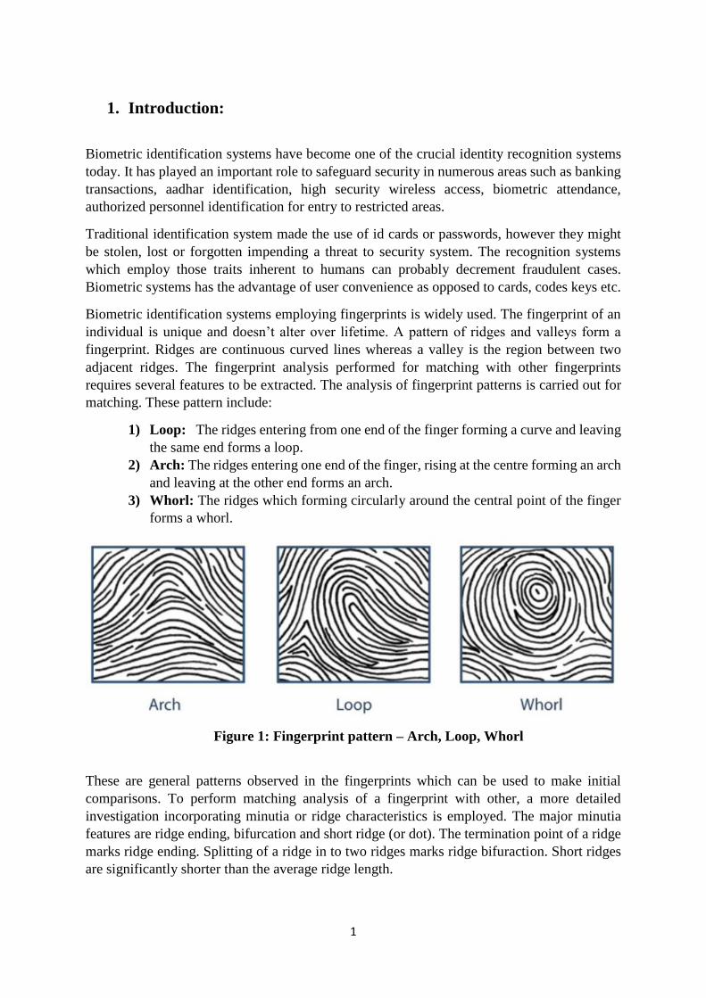
matching. These pattern include:
1) Loop: The ridges entering from one end of the finger forming a curve and leaving
the same end forms a loop.
2) Arch: The ridges entering one end of the finger, rising at the centre forming an arch
and leaving at the other end forms an arch.
3) Whorl: The ridges which forming circularly around the central point of the finger
forms a whorl.
Figure 1: Fingerprint pattern – Arch, Loop, Whorl
These are general patterns observed in the fingerprints which can be used to make initial
comparisons. To perform matching analysis of a fingerprint with other, a more detailed
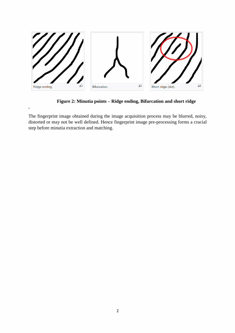
investigation incorporating minutia or ridge characteristics is employed. The major minutia
features are ridge ending, bifurcation and short ridge (or dot). The termination point of a ridge
marks ridge ending. Splitting of a ridge in to two ridges marks ridge bifuraction. Short ridges
are significantly shorter than the average ridge length.
2
Figure 2: Minutia points – Ridge ending, Bifurcation and short ridge
.
The fingerprint image obtained during the image acquisition process may be blurred, noisy,
distorted or may not be well defined. Hence fingerprint image pre-processing forms a crucial
step before minutia extraction and matching.

3
2. Fingerprint Image Pre-processing:
The first step in image enhancement is to segment out the finger image from the acquired
image. This is image segmentation. Once the fingerprint image is segmented, the process of
normalisation is carried out. This helps in normalizing the mean and variance of the image to
a pre-specified value. There are certain imperfections that arise out due to non-uniform ink
intensity, non-uniform pressure contact on the fingerprint device or camera image capture
under poor illumination or lighting conditions that affects the grey-level intensity values along
ridges and valleys which calls the need for normalisation of the image. Once the image is
normalised, then an orientation image which exhibit the matrix of directional vectors is
evaluated. These vectors represent the ridge orientation in each direction. These orientations
get distorted in the presence of noise and other such factors and hence Gaussain smoothing is
carried out on this oriented image to eliminate such effects. The next step is to compute the
frequency of ridges in the image. This is called the estimation of ridge frequency image. Once
the ridge frequency is calculated, the directional ridges are enhanced and other elements are
supressed using frequency-selective and orientation-selective Gabor filters. This enhances the
contrast level between the foreground ridges and background and supresses’ spurious noise
levels. Minutia extraction algorithms work on binary image and hence the filtered gray scale
image is converted to binary image and the process is called Binarisation. The binary image
has only two values: one for ridges and zero for non-ridges or valleys. The final step is thinning
which is a morphological operation, carried out to make ridges, one pixel thin. This final pre-
processed image is now ready for minutia extraction.
The following is a detailed description about image preprocessing:
1) Fingerprint Image Segmentation: The process of isolating fingerprint image consisting
of ridges and valleys in the foreground from the descriptive or non-descriptive background
is called segmentation. The background regions are outside the fingerprint boundary which
carry no fingerprint information and hence needs to be segmented out. If background
information is allowed, the minutia extraction algorithm will produce false minutia and
hence the matching will suffer. In touchless acquisition, when the camera flash light falls
on the finger image, the foreground finger image brightens up whereas the background
darkens. Thus foreground image represents high grey-scale covariance than background
and covariance thresholding can be used for segmentation. The image is divided in to
blocks and each block is processed through grey-scale variance. If it is above global
threshold, then it is considered to be a foreground fingerprint image else background
image. If the block size is W*W, then, the grey-level variance is defined as:
where I(i, j) is the grey-level value at pixel, M(k) is the mean grey-level value for the
block k and V (k) is the variance for block k.

4
Figure 3: Segmented Image from Original Image
Here, the variance threshold is kept at 100 and size of the block is 16*16.
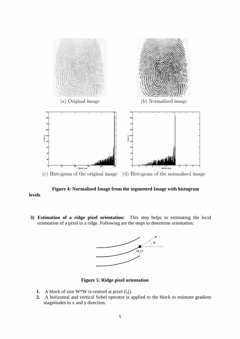
2) Grey-level value Normalisation: To convert the mean and variance of the acquired image
to pre-specified values, the process of normalisation is applied. If N(i,j) is the normalised
grey-level value at pixel (i,j), then,
where M and V are calculated mean and variance of image I(i,j) and M0 and V0 are pre-
specified mean and variance values respectively. Normalisation standardizes grey-level
intensity values to facilitate subsequent pre-processing stage and does not alter the
pattern of local ridge structure.
5
Figure 4: Normalised Image from the segmented Image with histogram
levels
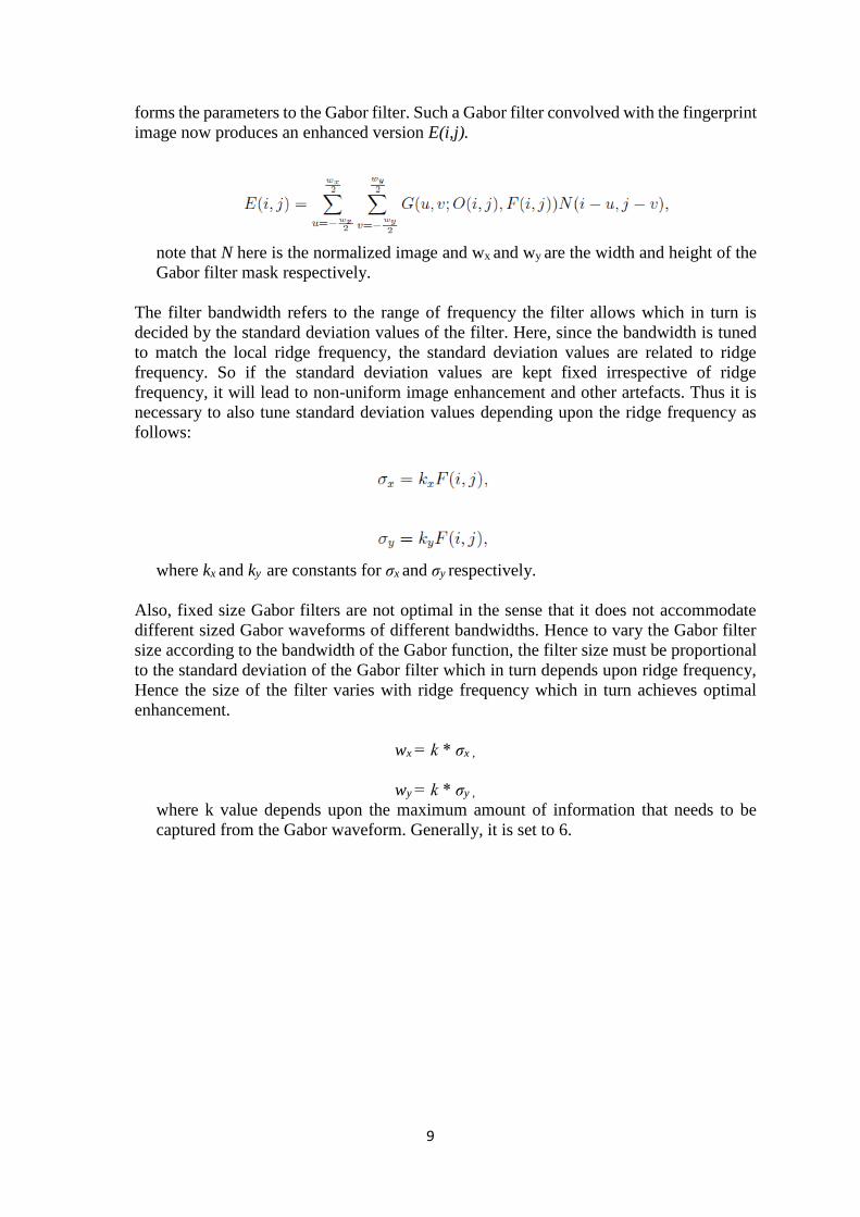
3) Estimation of a ridge pixel orientation: This step helps in estimating the local
orientation of a pixel in a ridge. Following are the steps to determine orientation:
Figure 5: Ridge pixel orientation
1. A block of size W*W is centred at pixel (i,j).
2. A horizontal and vertical Sobel operator is applied to the block to estimate gradient
magnitudes in x and y direction.

6
3. Local orientation is then determined as follows:
where θ(i, j) is the local orientation at the block at pixel (i, j).
4. Now, this orientation image is now converted to continuous vector field as:
and the Gaussain smoothing is applied on this:
Where G is a Gaussian low-pass filter of size wΦ * wΦ.
5. The orientation of the smoothed image O(i,j) is given by:
The following is the orientation image for the given synthetic image:

7
Figure 6: (a) Shows 200*200 synthetic image of wavelength 8 and (b) shows Orientation
image of the synthetic image with 0.0003 radians of mean square error between them.
4) Estimation of Ridge Frequency: Gabor filter requires orientation image along with the
ridge frequency image for its construction. Ridge frequency image is representative of
local ridges in an image. Here we divide the image in blocks of size W*W and then project
each of the grey-level pixel values in the block along a direction orthogonal to the local
ridge orientation. Thus a sinusoidal shape wave is obtained because of such projection
where the minima points correspond to ridges in the fingerprint as shown below:
Figure 7: (a) shows Projection of local intensity values from a 32*32 block along an
orthogonal direction to local ridge orientation. (b) shows Sinusoidal shape waveform
projection where local minima correspond to ridges

8
An additional step of Gaussian smoothing the projected waveform in ridge frequency
image estimation can be performed prior to calculating ridge spacing. This reduces any
noise disturbances caused while projection. The ridge spacing S(i,j) can be calculated by
couting the number of pixels between two consecutive minima points. Thus ridge
frequency F(i,j) is given by :
Whenever valid minutia points are encountered or there is no local minima points on
projection, a valid frequency estimation cannot be obtained. To solve such issues, we need
to interpolate the out of range frequency values using neighbouring blocks having well-
defined frequency values.
5) Gabor Filtering: Orientation image and Ridge Frequency Image together helps in
constructing an even symmetric Gabor Filter. A 2D Gabor filter is tuned to a particular
orientation and frequency consisting of a sinusoidal plane wave modulated by Gaussian
envelope. Such a filter gives maximal response when tuned to local ridge frequency
structure. It enhances the ridges and supresses non-ridge structure improving the local
contrast. When a cosine wave is modulated by a Gaussian, it gives an even symmetric
Gabor filter which is a real part of Gabor function. In spatial domain, it is represented as
follows:
Note that θ is the orientation of Gabor filter, f is the cosine wave frequency, σx and σy
are the standard deviation of Gaussian filter in x and y direction whereas xθ and yθ are
the x and y axis of the filter coordinate frame.
Figure 8: An even symmetric Gabor filter
This filter is spatially convolved with the fingerprint image. The convolution now requires
the computed orientation image value O(i,j) along with the frequency image F(i,j) that
9
forms the parameters to the Gabor filter. Such a Gabor filter convolved with the fingerprint
image now produces an enhanced version E(i,j).
note that N here is the normalized image and wx and wy are the width and height of the
Gabor filter mask respectively.
The filter bandwidth refers to the range of frequency the filter allows which in turn is
decided by the standard deviation values of the filter. Here, since the bandwidth is tuned
to match the local ridge frequency, the standard deviation values are related to ridge
frequency. So if the standard deviation values are kept fixed irrespective of ridge
frequency, it will lead to non-uniform image enhancement and other artefacts. Thus it is
necessary to also tune standard deviation values depending upon the ridge frequency as
follows:
where kx and ky are constants for σx and σy respectively.
Also, fixed size Gabor filters are not optimal in the sense that it does not accommodate
different sized Gabor waveforms of different bandwidths. Hence to vary the Gabor filter
size according to the bandwidth of the Gabor function, the filter size must be proportional
to the standard deviation of the Gabor filter which in turn depends upon ridge frequency,
Hence the size of the filter varies with ridge frequency which in turn achieves optimal
enhancement.
wx = k * σx ,
wy = k * σy ,
where k value depends upon the maximum amount of information that needs to be
captured from the Gabor waveform. Generally, it is set to 6.

10
Figure 9: Gabor filter enhanced fingerprint images with different kx and ky values
Here, σx determines the amount of contrast enhancement between subsequent ridges and
valleys whereas σy determines ridge smoothening extent along local orientation. If the
values of kx and ky is large, then it introduces unwanted artefacts and blurs the ridge
structures. This is because larger values will over-smoothen the image. If the values are
very small, then the filter is ineffective in removing noise. Thus it involves trade-off in the
selection of standard deviation values.
6) Binarisation and Thinning: To extract minutia from the fingerprint image requires it to
be in the binary format wherein the black pixels correspond to the foreground ridge
structures whereas white pixels corresponds to the background non-ridge structures or
valleys. Thus Binaristation converts grey-scale image to binary image which further
improves the contrast between the ridges and valleys thereby facilitating extraction of
minutia points. Gabor filters are zero mean filters which mean that the binarisation can be
easily performed by introducing a global threshold of zero. If the grey-level value of the

11
enhanced image is greater than the global threshold, then the pixel value is set to a binary
value of 1 else 0. Once the image is binarised, a morphological operation of selecting only
one pixel thin lines out of thick ridges is performed. This is called Thinning. The algorithm
detects which neighbourhood pixels are eligible to be deleted and works iteratively till no
more pixels can further be deleted. This algorithm preserves the connectivity of ridge
structures without introducing any line breakages or false contours. This is the skeleton
image which is used in extracting out minutia points like ridge endings and bifurcations.
Figure 10: Binarized and Thinned images of the enhanced image
.
The enhancement process is important before binarizing and thinning the fingerprint
image. This becomes clear from the following result:
Directly binarizing and thinning the original fingerprint image introduces line breakages
and increases the probability of extracting false minutiae. It also introduces significant
amount of noise and unwanted elements.
12
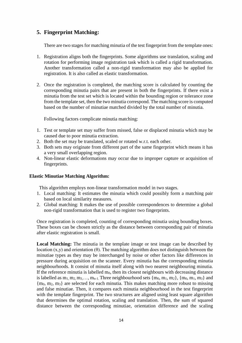
3. Extraction of Minutiae and Removal of False Minutiae:
The concept of Cross Numbering (CN) is used to extract out Minutiae. The skeleton image is
scanned with the help of 3*3 window over its ridges. Then, the CN value is calculated which
is half the mod of sum of the differences between pairs of adjacent pixels in 8-neighbourhood.
Ridge pixel can be classified as isolated point, ridge-ending point, continuing ridge point,
bifurcation point and crossing point according to the CN as follows:
Table. Ridge pixel property corresponding to CN value
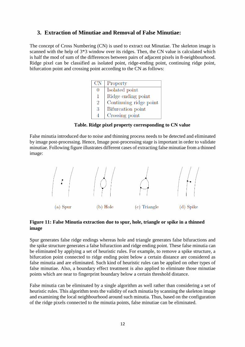
False minutia introduced due to noise and thinning process needs to be detected and eliminated
by image post-processing. Hence, Image post-processing stage is important in order to validate
minutiae. Following figure illustrates different cases of extracting false minutiae from a thinned
image:
Figure 11: False Minutia extraction due to spur, hole, triangle or spike in a thinned
image
Spur generates false ridge endings whereas hole and triangle generates false bifuractions and
the spike structure generates a false bifuraction and ridge ending point. These false minutia can
be eliminated by applying a set of heuristic rules. For example, to remove a spike structure, a
bifurcation point connected to ridge ending point below a certain distance are considered as
false minutia and are eliminated. Such kind of heuristic rules can be applied on other types of
false minutiae. Also, a boundary effect treatment is also applied to eliminate those minutiae
points which are near to fingerprint boundary below a certain threshold distance.
False minutia can be eliminated by a single algorithm as well rather than considering a set of
heuristic rules. This algorithm tests the validity of each minutia by scanning the skeleton image
and examining the local neighbourhood around such minutia. Thus, based on the configuration
of the ridge pixels connected to the minutia points, false minutiae can be eliminated.

13
4. Minutia extraction algorithm:
The Cross Numbering method extracts minutiae i.e. ridge endings and bifurcation points from
the skeleton image obtained from thinning process by examining the local neighbourhood of
every ridge pixel by a 3*3 window. The Cross Numbering value for a ridge pixel P is estimated
as follows:
Where Pi is a pixel neighbouring to pixel P. The 8 pixels neighbouring to pixel
P is scanned as follows:
Figure 12: 3*3 window with P as ridge pixel and others as neighbouring pixels
Figure 13: Ridge Ending (a) and Bifucation (b) examples with Crossing Number
The above figure shows two examples: Ridge Ending and Bifurcation. The dotted square
denoted a 3*3 mask as shown above. The centre pixel P is a ridge pixel and the mask around
it is used to compute CN value using the equation of CN as described above. Those with black
squares are labelled as 1 and the ones with white are labelled as 0. Once the CN of a ridge pixel
is computed, it can be classified according to the property of its CN value as tabulated above.
If CN =1, it marks the ridge pixel as a ridge ending point. If CN=3, it’s a bifurcation point.
Now, once the minutiae are extracted, the following information is stored in the form of
fingerprint template for matching purpose:
1. X and Y coordinates of the minutia point in the fingerprint image
2. Orientation in degrees of the associated ridge structure
3. Classification of minutiae (ridge ending or bifurcation)
14
5. Fingerprint Matching:
There are two stages for matching minutia of the test fingerprint from the template ones:
1. Registration aligns both the fingerprints. Some algorithms use translation, scaling and
rotation for performing image registration task which is called a rigid transformation.
Another transformation called a non-rigid transformation may also be applied for
registration. It is also called as elastic transformation.
2. Once the registration is completed, the matching score is calculated by counting the
corresponding minutia pairs that are present in both the fingerprints. If there exist a
minutia from the test set which is located within the bounding region or tolerance zone
from the template set, then the two minutia correspond. The matching score is computed
based on the number of minutiae matched divided by the total number of minutia.
Following factors complicate minutia matching:
1. Test or template set may suffer from missed, false or displaced minutia which may be
caused due to poor minutia extraction.
2. Both the set may be translated, scaled or rotated w.r.t. each other.
3. Both sets may originate from different part of the same fingerprint which means it has
a very small overlapping region.
4. Non-linear elastic deformations may occur due to improper capture or acquisition of
fingerprints.
Elastic Minutiae Matching Algorithm:
This algorithm employs non-linear transformation model in two stages.
1. Local matching: It estimates the minutia which could possibly form a matching pair
based on local similarity measures.
2. Global matching: It makes the use of possible correspondences to determine a global
non-rigid transformation that is used to register two fingerprints.
Once registration is completed, counting of corresponding minutia using bounding boxes.
These boxes can be chosen strictly as the distance between corresponding pair of minutia
after elastic registration is small.
Local Matching: The minutia in the template image or test image can be described by
location (x,y) and orientation (θ). The matching algorithm does not distinguish between the
minutiae types as they may be interchanged by noise or other factors like differences in
pressure during acquisition on the scanner. Every minutia has the corresponding minutia
neighbourhoods. It consist of minutia itself along with two nearest neighbouring minutia.
If the reference minutia is labelled m0, then its closest neighbours with decreasing distance
is labelled as m1, m2, m3,…, mn-1. Three neighbourhood sets {m0, m1, m2}, {m0, m1, m3} and
{m0, m2, m3} are selected for each minutia. This makes matching more robust to missing
and false minutiae. Then, it compares each minutia neighbourhood in the test fingerprint
with the template fingerprint. The two structures are aligned using least square algorithm
that determines the optimal rotation, scaling and translation. Then, the sum of squared
distance between the corresponding minutiae, orientation difference and the scaling
15
determines the similarity between two minutia neighbourhoods. If the structures match,
then the pair of minutia neighbourhoods and the transformations (t,s,r) consisting of
translation t = (tx,ty), scaling (s) and rotation (r) is stored. Once each minutia neighbourhood
in test fingerprint is compared with each of the minutia neighbourhood in the template
fingerprint, a list of corresponding minutia neighbourhood pairs is obtained. All of the
minutia neighbourhood pairs might not give an indication of true correspondences but is
the first step to the degree of similarity between the two fingerprints.
Global Matching: This stage requires the design of global transformation model that
optimally registers two fingerprints. The list of minutia neighbourhood pairs that exhibit
local similarities are utilized to determine the global transformation. This transformation
selects the largest number of matching minutia pairs from the entire minutia sets. Initially,
the largest group of pair of minutia neighbourhood that share approximately the same
registration parameters are selected. This can be achieved by analysing, for each matching
pair, the number of pairs for which the registration parameters differ less than a certain
threshold. Then the transformation (t,r,s) needs to be calculated in least square sense that
optimally registers the selected minutiae in the test set to the corresponding minutiae in the
template set. Here the problem comes only for elastically deformed fingerprints which
won’t be well registered due to non-existence of an accurate rigid registration. This needs
to be compensated in the counting stage. Elastic registration model like the TPS (Thin plate
spline) model needs to be considered in order to compensate for elastic distortion. This TPS
model needs to be fitted in a number of iterations. Firstly, an initial model is fitted to the
minutia in the minutia neighbourhood pairs that were found in the local matching stage.
Then, the corresponding minutia in both the sets which differs in location and orientation
less than a pre-determined threshold, are estimated and a new model is fitted to those
corresponding minutiae. This gets repeated again and again, each time with a decreasing
threshold r0 until the model converges to its final state. This iterative process improves the
quality of the non-linear registration significantly leading to an increased match score. The
matching score is finally computed as follows:
where nmatch = no. of matching minutiae, n1 = number of minutiae in the test fingerprint
and n2 = number of minutiae in the template fingerprint. This equation gives optimal
results of false acceptance and false rejection for fingerprints with lesser minutiae. The
match and non-match decision is then taken depending upon a pre-determined threshold.

16
6. Android App Implementation:
The Touchless Fingerprint application developed using Android platform is a Criminal
Identification System App which can be used by Police Authority to identify criminals/suspects
on the field. The application provides three facilities to capture fingerprints using Mobile phone
Camera (touchless) or Fingerprint Scanner (Touch based) or phone gallery (acquired/saved
fingerprints). Pre-processing and Template Extraction of finger images is performed in the
mobile phones and these templates are sent over-the-air, in the encoded format, to the server.
The server stores the training set of fingerprint templates in to its own local Database during
the enrolment phase. During the identification phase, the server acquires the test fingerprint
template and performs matching operation of it with the stored templates in the database. The
matching score is calculated by the server. If the matching score goes above a predefined
threshold, then the closest match is identified. The person’s name corresponding to the closest
match fingerprint template having the maximum matching score is returned by the server to
the mobile phone. This helps the police authority to identify the criminals/suspects on the field
using only a mobile phone.
The Touchless fingerprint application is developed for mobile phones operating on Android
Platform using Android Studio 2.3.1. The application is tested on Lenovo Vibe K5 plus having
following features:
Processor Octa-core Qualcomm Snapdragon 616
Speed 1.5 GHz
RAM 3 GB
Android Version 5.1.1
Code name Lollipop
API Level 21
The minimum requirement of the application to be compatible with the android handset is as
follows:
Source Compatibility Java Version 1.8
Target Compatibility Java Version 1.8
Min SDK Version 21
Min API Level 21
The android application was developed in the following environment:
Android Studio Version 2.3.1
Java Version 1.8 (Jack Enabled)
Compiled SDK Version 24
Build Tools Version 25.0.0
Target SDK Version 24
Build Gradle Version 2.3.1

17
7. Touchless Fingerprint App Description:
The first activity provides three options for the user:
1) Camera: The camera further provides three options:
i) Enrol: In the enrolment option, first the authority police is asked to enter its login
id and password. This ensures that the enrolment can be done only by police
authority or with the consent of police authority. Once the login is successful, there
are two options for enrolment of authority and suspects. By clicking on either of the
options, a form is displayed. The police authority is asked to enter new login id and
password for a new police authority entry along with other personal details like first
name, last name, address, date of birth, gender, aadhar-id, photo, camera fingerprint,
scanner fingerprint whereas suspects have a unique suspect id along with such
personal details. The information of the police authority is stored in the separate
table, enrollment_authorization, of the fingerprint database whereas the information
about the suspects is stored in the other table, suspects_enrollment, in the same
database. Thus, this option enrols the fingerprints along with other personal
information in the database.

18

19
ii) Verify: This option is used to verify two fingerprints. Once the add fingerprint is
clicked, the user is asked to give the finger image through mobile camera. The
mobile phone extracts out fingerprint template out of the image and performs
matching operation with the other fingerprint template obtained from the second
option of add fingerprint. If the matching score is above the predefined threshold,
then the “Fingerprint Matched” message is displayed else “Fingerprints Not
Matched”.
iii) Identify: This option acquires the finger image from the mobile camera, extracts
out the fingerprint template and sends it to server via a socket port. After sending
the fingerprint template, it waits for the response from the server displaying whether
the person is identified or not.
20
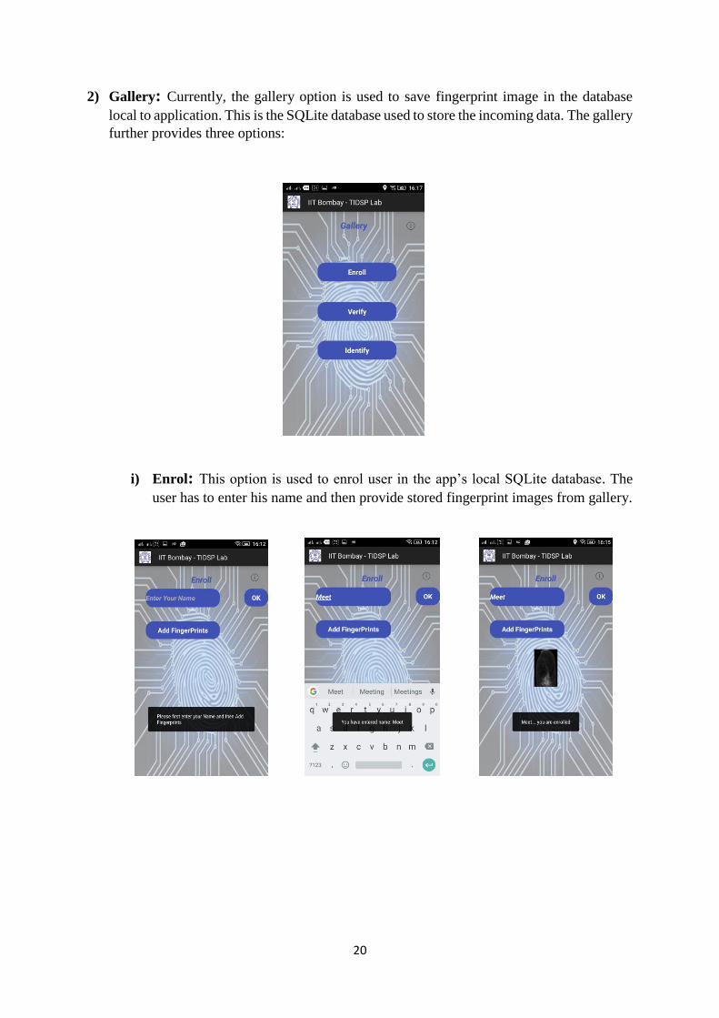
2) Gallery: Currently, the gallery option is used to save fingerprint image in the database
local to application. This is the SQLite database used to store the incoming data. The gallery
further provides three options:
i) Enrol: This option is used to enrol user in the app’s local SQLite database. The
user has to enter his name and then provide stored fingerprint images from gallery.
21
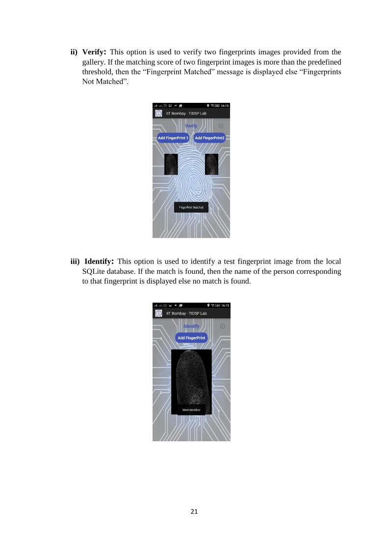
ii) Verify: This option is used to verify two fingerprints images provided from the
gallery. If the matching score of two fingerprint images is more than the predefined
threshold, then the “Fingerprint Matched” message is displayed else “Fingerprints
Not Matched”.
iii) Identify: This option is used to identify a test fingerprint image from the local
SQLite database. If the match is found, then the name of the person corresponding
to that fingerprint is displayed else no match is found.

22
3) Scanner: The enrolment using fingerprint scanner is done in the enrolment phase of the
camera option. The fingerprint scanner device is attached to the mobile phone via a USB-
OTG cable. The scanner provides two options:
i) Verify: Once the device is connected, the user is asked to place the finger on the
scanner device. The fingerprint is captured and its template is extracted and the
matching operation is performed. If the matching score is above the predefined
threshold, then the “Fingerprint Matched” message is displayed else “Fingerprints
Not Matched”.
23
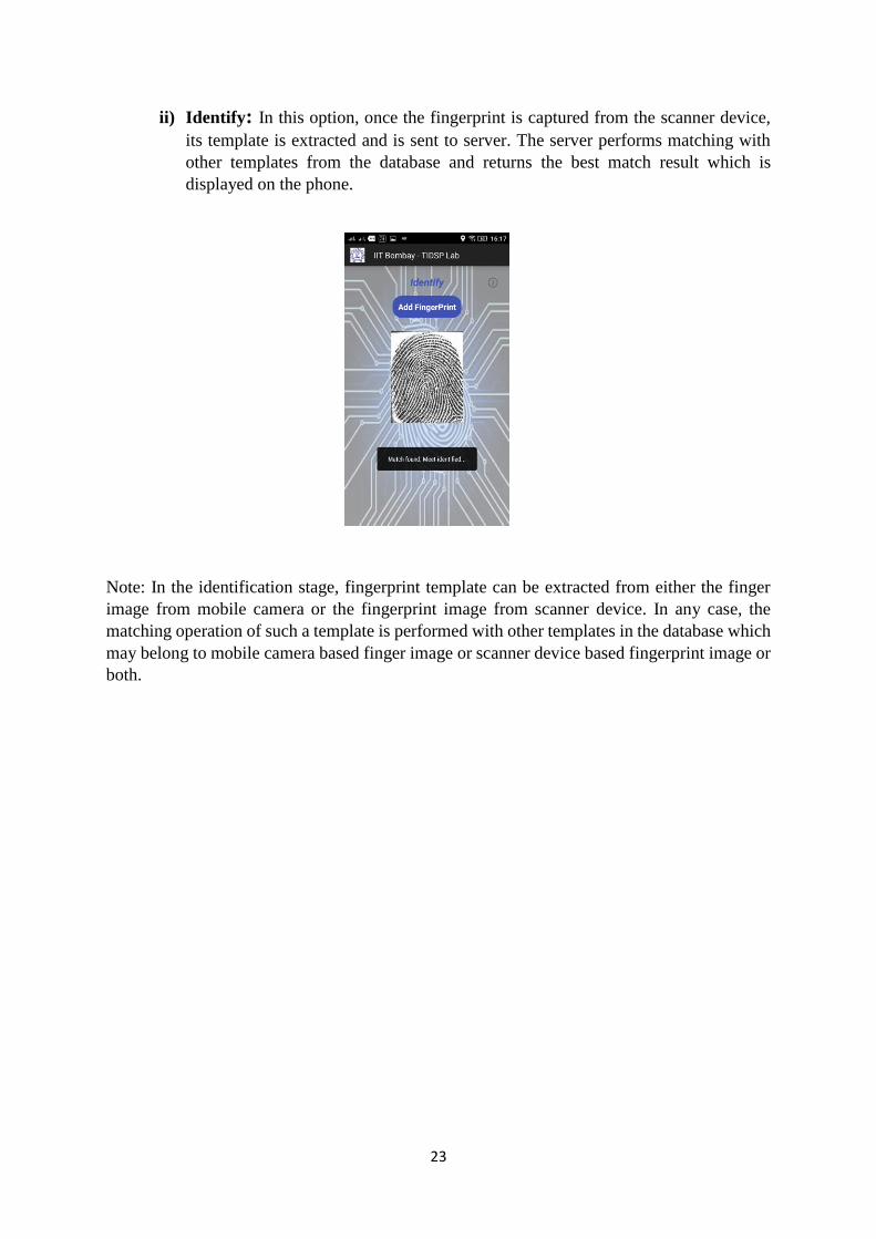
ii) Identify: In this option, once the fingerprint is captured from the scanner device,
its template is extracted and is sent to server. The server performs matching with
other templates from the database and returns the best match result which is
displayed on the phone.
Note: In the identification stage, fingerprint template can be extracted from either the finger
image from mobile camera or the fingerprint image from scanner device. In any case, the
matching operation of such a template is performed with other templates in the database which
may belong to mobile camera based finger image or scanner device based fingerprint image or
both.
24
8. Web Server and Database:
XAMPP is an open source, cross platform package and it stands for cross platform (X), Apache
(A), MySQL (M), PHP (P) and Perl (P). XAMPP server is being used to deal with server side
communication and to deal with Databases. Every web application requires to store data in to
the database. MySQL queries are used to query the database. PHP (Hypertext pre-processor)
is a server side scripting language which is used on the server side to communicate with the
app and the database. PHP scripts are stored on the server and holds MySQL queries. These
scripts are used to connect to the database by providing the database name, username, password
and server name to MySQL query.
Once the database is connected to server, the tasks of logging in or registering the details is
performed in other PHP script. The script to be run and other user credentials are sent from the
mobile phone via http server connection to the server. When the XAMPP control panel modules
like Apache and MySQL is started, the server receives this data sent from mobile phone. The
mentioned PHP script is run on that server. For eg: if the script is formregister.php , as in this
case, it first receives those credentials from the server, runs the SQL query by opening the
database connection and stores the content in to the database. This way, the registration and
logging data is sent from mobile phone to the server and the server performs the required action
on the database. The response string can also be sent back to mobile phones from server using
this PHP script as described next.
PhpMyAdmin is an open-source package available within Xampp to work with MySQL and
MariaDB with the use of web browser. Here the database handling is done by phpMyAdmin.
It provides the following:
1) MySQL and MariaDB database management
2) Imports data form SQL and CSV
3) Facilitates SQL query execution on tables and databases to perform manual operations
on them.
4) It helps in administering multiple servers.
5) It also provides a better web interface.
6) Data can be exported in various formats like PDF, XML, SQL, CSV, Word, Excel,
LaTeX etc.
7) Helps in searching entities in the database locally as well as globally.

25
9. Mobile-Server Communication: HTTP URL Connection:
All the user information and login credentials are stored in the form of Strings. The fingerprint
template extracted from the image is in the form of Java object. These objects are converted to
JSON (JavaScript Object Notation) strings using GSON. GSON(Google Gson) is an open
source Java library to serialize and deserialize Java Objects to and from JSON. Finally, the
data to be sent is available in the String format. Thus, the mobile phone collects the data from
the form or login credentials from the activity and posts it to the server via HTTP URL
Connection. It sends the buffered data on the output stream by opening the URL connection in
an encoded “UTF-8” format. The URL string contains the ip-address of the network to which
the data needs to be posted followed by the PHP script name. (For eg:
http://10.107.79.150/formregister.php). The mobile phone can also receive the data from PHP
script via input stream to know about the connection or whether the registration is successful.
Figure 14 : Touchless Fingerprint Identification System

26
10. Java Socket Communication:
In the identification phase, the fingerprint template that needs to be sent from the mobile phone
to server is done via socket communication. The server ip-address and port address is set in the
socket and the data is sent from the mobile phone through this socket to the server. On the
server side, this data is accepted by the Eclipse IDE which runs a java socket program to accept
the data. The java socket program is always in the listening mode in order to accept the data
anytime from the mobile phone and its connection is never closed. Once the application
receives the fingerprint template in JSON string format, it deserializes the string back to JSON
object or Java object. Then, the SQL database connection is invoked from the eclipse and the
stored templates are retrieved one by one. Each of the retrieved template is in the JSON string
format which needs to be deserialized to java object using GSON. Once the retrieved template
is converted back to java object, it is passed on to the matching algorithm which returns the
matching scores of the test template with that of the retrieved templates from the database. The
person name corresponding to the highest match score above the pre-determined threshold is
sent back to the mobile phone through the existing socket connection and is displayed.
Figure 15 : Java Socket Communication

27
11. SourceAFIS Libraries:
SourceAFIS is an opensource project initiated by Robert VanZan which provides an SDK for
fingerprint recognition and matching. The library is implemented in C#, .NET and Java. The
SourceAFIS Java SDK involves various packages like extraction, filters, minutiae, model,
matching, templates etc. which can be used for minutiae extraction and matching.
28
12. Conclusion and Future Work
Using mobile – webserver communication in a secured manner, it has become convenient to
acquire fingerprints just from a smartphone without any dedicated and costlier fingerprint
scanner, extract out minutiae from the pre-processed fingerprint image and perform matching.
When it comes to acquiring fingerprints from devices like mobile phones which is possessed,
nowadays, by almost everyone, it becomes a more popular choice because of convenience and
feasibility. Also, mobile phone cameras provide a greater depth of resolution in 3D which
fingerprint scanners fail to provide. This gives more information about the fingerprint which
in turn improves the accuracy of matching decreasing FAR and FRR rates. Also the problem
of deformation due to differences in pressure while acquiring fingerprints form scanner is
eliminated. Since the quality of fingerprints acquired from mobile phone cameras is resolution
dependent, at first sight it seems to be a drawback, but the rising technology trends that provide
best resolution cameras in cheaper phones makes resolution dependency, less of a problem. A
minimum of 8 MP front camera resolution can acquire best images which can be conveniently
pre-processed. Once pre-processing is done, true minutiae can be extracted easily eliminating
the false minutiae occurrences. Thus, the touchless mobile phone fingerprint acquisition have
become an emerging trend in the field of fingerprint biometrics that will soon replace the
traditional fingerprint scanners, safeguarding the security in a more convenient way.
The future work is as follows:
1) Improving the touchless acquisition process without asking user to tap on the screen.
This can be achieved by detecting finger inside the bounding box and triggering
autofocus. Once the finger image is under focus, the image can be automatically
captured. Thus the only obligation for the user that remains is to adjust the finger in the
bounding box.
2) An alternate approach to fingerprint pre-processing using Monogenic wavelets needs
to be tested against the traditional method described in this report. Monogenic wavelet
based pre-processing provides a more accurate way of enhancing finger images that
further improves matching accuracy.
3) Incorporating multimodal biometrics in this app. Palmprint along with fingerprint
acquisition will further improve identification accuracy and security. Palmprint also
involves ROI extraction, pre-processing, feature extraction and matching. Feature
extraction in palmprint can be done using convolutional scattering networks.
4) A different approach to minutia extraction and matching of fingerprints acquired from
mobile phone camera is required. More specifically, a machine learning approach to
fingerprint matching can be done to improve the accuracy of matching score.
5) A study on finger knuckles, its uniqueness and building an identification system to be
incorporated in the multimodal biometric app is also a part of future work.

29
13. References:
1. Hong, L., Wan, Y., and Jain, A. K. Fingerprint image enhancement: Algorithm and
performance evaluation. IEEE Transactions on Pattern Analysis and Machine Intelligence 20,
8 (1998), 777–789.
2. Jain, A. K., Hong, L., and Bolle, R. M. On-line fingerprint verification. IEEE Transactions on
Pattern Analysis and Machine Intelligence 19, 4 (1997), 302–314
3. Prabhakar, S., Wang, J., Jain, A. K., Pankanti, S., and Bolle, R. Minutiae verification and
classification for fingerprint matching. In Proc. 15th International Conference Pattern
Recognition (ICPR) (September 2000), vol. 1, pp. 25–29
4. A.K. Jain and N.K. Ratha. Object detection using Gabor filters. Pattern Recognition,
30(2):295–309, February 1997
5. Thai R., Kovesi P., Honours Programme of the School of Computer Science and Software
Engineering, The University of Western Australia, 2003.
6. A.M. Bazen and S.H. Gerez. Achievements and Challenges in Fingerprint Recognition. In D.
Zhang, editor, Biometric Solutions for Authentication in an e-World, pages 23–57. Kluwer,
2002
7. A.M. Bazen and S.H. Gerez. Elastic Minutiae Matching by means of Thin-Plate Spline Models.
In Proc. ICPR 2002, Quebec City, August 2002
Web References:
1. https://developer.android.com/samples/Camera2Basic/index.html
2. http://www.sourceafis.org/blog
3. https://examples.javacodegeeks.com/android/core/socket-core/android-socket-example
4. https://www.tutorialspoint.com/sql
5. https://www.tutorialspoint.com/php
6. https://www.siteground.com/tutorials/phpmyadmin
7. https://blog.udemy.com/xampp-tutorial
8. https://www.youtube.com/watch?v=kkSG19gQamc
9. https://www.youtube.com/watch?v=ZOrYOwJYGls
10. https://www.mkyong.com/java/how-do-convert-java-object-to-from-json-format-gson-api/