Embed Size (px)
Citation preview

1
Total lifecycle information sharing system of consumer electronics with globally unique identifier Jin Mitsugi, Hsakazu Hada and Tatsuya Inaba
Auto-ID Labs White Paper WP- HARDWARE-049
April, 2012
Jin Mitsugi Associate Professor Keio University
Hisakazu Hada Associate Professor Tokyo University of Technology
Tatsuya Inaba Associate Professor Kanagawa Institute of Technology
Contact: Jin Mitsugi Keio University Phone +81-3-3516-0620 http://www.autoidlab.jp
Har
dwar
e

2
Abstract Total lifecycle information sharing system of industrial products, particularly targetting consumer electronics (CE), is presented. EPC (Electronic Product Code) of CE is stored in embedded dual interface RF tag and thus can be retrieved through both the RFID air interface and the baseband interface. This way, consumers can discover and access services associated with the CE by using EPC architecture even when the CE is connected to the network in consumer’s premise; i.e., home network. We develop a prototype of such extended EPC network. CEs are automatically recognized by the information system immediately after they are associated to home network by using UPnP mechanism. In our implementation, the home network is composed of Ethernet and ZigBee segment. UPnP extension using CoAP is developed to seamlessly establish end-to-end communications over the ZigBee segment. The prototype involves about 50 appliances with 180 sensor data connected with IPv6 network. We also evaluate and identify the performance bottleneck of the prototype.

3
1 Introduction According to a report from Center for retail research [1], the world total annual retail shrinkage, which denotes the loss of commercial products during their supply chain, is $119 billion. Top three factors of the loss are customer shoplifting ($51.5 billion), employee theft ($41.7 billion) and internal errors ($19.4 billion). These figures are in line with the presentation by Mark Robetti in IEEE RFID 2011 in Florida USA. He revealed that shoplifting loss in the US is $11.7 billion, employee theft is $14.4 billion and administrative error is $4.9 billion, annually, which is about one fifth of the world total. $119 billion annual global loss is equivalent to GDP of countries like Vietnam, Hungary and Qatar. Many initiatives to achieve efficiency in supply chain management (SCM) have been proposed and executed. ID information system with automatic identification technology such as RFID has been considered as the key to efficient SCM and store management. It is apparent from the earlier loss analysis that the ID information system architecture needs to be shared with many services such as SCM and EAS (Electronic Article Surveillance).
Reduction of green house effect gas emission is also a global issue. In Japan, while the total amount of emission stays almost the same since 1990 (about 1.2 billion metric ton: CO2 equivalent [2]), the emission from households, about 15% of the total, has been increasing. A household in Japan emits 4,852 kg-CO2 in average annually [3]. About one third of the emission is from electronics including lighting and appliances in addition to 14% of heating and cooling majority of which is provided by electronics (Figure 1). It is essential to operate electronic appliances in household in an efficient way not just to reduce environmental impact but also to reduce consumer’s expenditure.
Figure 1 CO2 emission from a Japan household in 2009 (produced from [3])
There are, accordingly, a number of initiatives on home electronics management system (HEMS). The strong motivation toward energy saving is partly because of the shortage of power supply due to the problem on nuclear power plant.
Heating13%
Cooling1%
Boiler13%
Kitchen4%
Electronics31%
Automobile33%
Garbage3%
Water2%

4
The above two stories on SCM and CO2 reduction illustrate that industrial products are usually subjected to a number of information systems over their lifecycle, from manufacturing control, SCM, EAS, HEMS and disposal and recycling. Presently, such services are independently designed and executed to solve particular problems. When it comes to the total life cycle information sharing involving in consumer premise, however, it is strongly demanded that every service can be discovered and used by consumers through a standardized interface because of the usability. This is not to say that all the services should be provided by one application. Rather, we seek a system by which consumer can freely subscribe and even provide services on industrial and personal products. The authors are particularly interested in the establishment of total life cycle information sharing system of consumer electronics (CE).
Extensive examination on existing technology for sensor network and Internet of Things
(IoT) [4][5][6][7][8][9][10] revealed that EPC architecture provides a good foundation for the information platform. We have already revealed extensions to EPC architecture to accommodate services in consumer premises such as energy management, remote monitoring, repairs and social services [11][12][13].
In this report, we introduce the extended EPC network for the total life cycle information
sharing of consumer electronics. In the system, EPC of consumer electronics in consumer premise network can be automatically collected and provides the consumer a list of services associated to the EPC. Our basic presumption is that we apply a dual interface RF tag [14][15] [16] to consumer electronics. Dual interface RF tag, which can be read and written by RFID interrogator through RF interface and also can be accessed by base band interface. We connect the base band interface to ZigBee sensor network in our latest implementation as shown in Figure 2. Since the ZigBee network is connected to IP network, we can retrieve and store information in RFID tag chip through ZigBee and IP network. The mechanism and protocol can be readily applied to a different access network such as WiFi, Bluetooth and power line communications.
Figure 2 Dual interface RF tag schematic
RFID Tag chip
RF interface
Baseband interface
Level converter
Sensor Controller (MSP430)
Antenna
ZigBeeTransceiver
sensor unit
GPIO

5
This report is organized as follows. In Section 2 we overview the prototype implementation. In Section 3, service subscription and polling mechanism with EPC retrieved from dual interface tag with UPnP protocol are explained. In Section 4, we evaluate the performance of the system. Section 5 concludes the report. This report is a compilation and detailed version of academic conference presentations [11][12][13].

6
2 Working prototype introduction
Currently Auto-ID Lab Japan is operating about 50 consumer electronics and sensor devices in 4 geographically separated location for campus energy monitoring system and remote management of consumer electronics. In each location we have a combination of Ethernet and ZigBee. Each CE and sensor
device is equipped with sensor, the total number of sensors we are managing is above 180. We connect each subnet with Ethernet or WiMAX using IPv6 network as shown in Figure 3.
Figure 3 Prototype network
The prototype network comprises home network components, such as a control point, UPnP device, gateway, ZigBee coordinator and end devices, and infrastructure components such as ONS, repository and service applications. Figure 4 shows the network hardware. Gateway is a board computer, PC engine Alix, which works as the virtual UPnP device for appliances connected non-IP network, in our case, ZigBee. Gateway is the end point of IP communications. Note that application communication to ZigBee devices is purely end-to-end and, thus, transparently transferred over the gateway as shown in Figure 5. In the figure it is shown that Data XML is transported between Consumer apparatus and Applications without any intervention of from Coordinator or Gateway. This is enabled by the consistent HTTP/CoAP transport.
IP network
Object naming service
Lab
ZigBee
大学教室
ZigBee
Volunteersoffice
ZigBee
Studenthouse
ZigBee
Campus Classroom
WiMAX
WiMAX
EthernetEthernet
データレポジトリ アプリケーション
アプリケーション
applicationsデータレポジトリ
Repository
Number of sensors + CEs>50Sensor data > 180
ID
ID
ID
Web
IPv6

7
Figure 4 Hardware implementation of dual interface RF tag with ZigBee transceiver
Figure 5 Fundamental protocol stack
Because of the end-to-end communication characteristics, one appliance data can be subscribed by many applications with which we can eliminate a central data repository. This principle is similar to EPCIS capture interface where an application can subscribe capture event of an interrogator as it wishes. For example, CE manufacture can provide remote maintenance service to an appliance in consumer’s premise. The appliance can feed data to energy management service provided by, for example, home builder company which supervises all the appliances in a premise. Similarly, one application can associate with many appliances in different places (Figure 6).
ZigBee Transceiver
MSP430 MCU
Gateway ZigBee Coordinator
ZigBee Router/End device
AlixCentOS 5.0UPnP HTTP‐CoAP translation
Digi Connect Port Network address translation(URI ‐>ZigBeeaddress)
Subscription/ Even controlSensor accomodation
Gen2 chip R8C MCU
ZigBee or6LoWPAN
etc
Consumer apparatus(end‐device)
Coordinator Gateway
Serial
Data XML
CoAP CoAP HTTP
Control XML
IPv6
Ethernet
TCP
Data XMLData XML
Application

8
Figure 6 End-to-end communication in application layer provides flexible service binding
One of the features of the prototype is automatic commission of appliances using UPnP. When consumer electronics is powered on in the prototype network, it automatically registered to a UPnP control point by sending JOIN message. We extended UPnP to accommodate EPC at the time of commission. This way, we can lookup services associated with particular EPC by using ONS. Figure 7 shows the screen shots of the procedure. In this case we discover appliances connected to home UPnP network (upper left) and pick one of them, a refrigerator (lower left), and look up services associated with the EPC (right upper) and finally connect to a manual page of the refrigerator (right lower).
Figure 7 Screen transition of CE inventory over home network
ZigBee
ZigBee
Internet
Remote monitoring
Device management
Ethernet/WiFi
Service discovery (ONS)
Environment monitoring
Social serviceEthernet/WiFi
one application ‐many sensors communications
one sensor ‐ many applications communications
Consumer A premise
Consumer B premise
GatewayVirtual UPnP device
control point
control point
UPnP device
click List of Services associated with the clicked EPC
click on manual
ONS lookup
User manual
urn:epc:id:sgtin:xxxxxxxxx.xxxxx.xxxurn:epc:id:sgtin:xxxxxxxxx.xxxxx.xxxurn:epc:id:sgtin:xxxxxxxxx.xxxxx.xxxurn:epc:id:sgtin:xxxxxxxxx.xxxxx.xxxurn:epc:id:sgtin:xxxxxxxxx.xxxxx.xxxurn:epc:id:sgtin:xxxxxxxxx.xxxxx.xxxurn:epc:id:sgtin:xxxxxxxxx.xxxxx.xxxurn:epc:id:sgtin:xxxxxxxxx.xxxxx.xxxurn:epc:id:sgtin:xxxxxxxxx.xxxxx.xxxurn:epc:id:sgtin:xxxxxxxxx.xxxxx.xxx
List of commissioned
EPCs

9
The information flow of the automatic commission starts by reading the EPC stored in the dual interface tag of an appliance by a sensor micro controller unit (MCU), as shown in Figure 8. We have two types of MCUs, namely, Renesas Electronics R8C and Texas Instruments MSP430 in the prototype PCB as shown in Figure 4. The reason we have two MCUs is because we need to accommodate various sensor interfaces with a single PCB design. If we can specialize to a particular service (resulting in a limited number of interfaces), MCU could be one chip with one transceiver. In some case, furthermore, the MCU function could be merged into a transceiver chip. We extensively use CoAP[17] as application protocol because it is light weight and still directly compatible with HTTP.
Figure 8 Association to ZigBee network with EPC
After the ZigBee network association, the gateway produces a virtual UPnP device for the appliances and join UPnP network as shown in Figure 9. In the figure, it is shown that after the completion of Join/Ack process the gateway creates UPnP device on behalf of the corresponding ZigBee device.
R8C MSP430 ZigBeeTransceiver
ZigBeeCoordinator Gateway
Serial ZigBee SerialSerial
Dual interface RFtag
GPIO
Sensor device
Beacon request
Beacon
Association Request
Association Ack
Retrieve EPC from baseband
AssociationNotification
Retrieve EPC
Join/CoAP/ZigBee

10
Figure 9 Automatic commission of an appliance
Control point looks up ONS upon consumers’ request and retrieves a list of services in the form of html or WSDL. For a consumer application, it is likely we first connect to service introduction page. A service is allowed to connect to the appliance and start communications, only after end user agrees the terms and condition of service.
Figure 10 Associations of applications to an appliance
Since an appliance is connected to home network either by ZigBee or Ethernet, we can
continually collect sensor data from appliances.
Sensor MCU
ZigBeeCoordinator Gateway Control
point
Association Request
SSDP: alive
Virtual UPnP device creation http:get
http:response
Ack
ZigBeeEnd Device
Association Association
Join
ZigBee SerialUART UPnP
Sensor device
ZigBeeEnd Device
ZigBeeCoordinator Gateway
http: subscribe service by notification
http: Control and EventingTransfer message
Control or Eventing
Report
http: Acknowledgement
Transfer report
http: Report
Control point Applications
ZigBee Ethernet EthernetSerial
SensorMCU
UART
Sensor device

11
Figure 11 shows an implementation of the EPC enabled sensor board(end device) to a refrigerator. We intentionally exposed the sensor board in the figure to show how it is connected. Since the sensor board is monitoring the communications between the front door MCU and the MCU inside, we can monitor the temperatures in compartments and compressor status
Figure 11 Sensor enabled refrigerator
Since an EPC can be read from RF interface, we can use RFID enabled smart phone to read the EPC through RFID air interface. We developed a smart phone application to read EPC and discover service using ONS. Figure 12 shows a screen shot of smart phone application.
Figure 12 Smart phone screen shot after inventory
In the figure, binary EPCs are shown in the screen accompanied with small figures of the product. Once EPC is read either from the baseband interface or from RFID air protocol, consumer can discover services associated with the EPC.
Sensor device
Front door PCB

12
The whole architecture of the prototype is shown in Figure 13. It is natural to treat a sensor as EPCIS repository and access it with extended EPCIS query interface. Sometimes sensor is requested to automatically transmit data but sometimes we need to poll queries. Subscribe and poll functions are well suited for this type of operation.
Figure 13 Extended EPC architecture
Interrogator
RFID TagEPC
Middleware
CapturingApplication
EPCISRepository Application
ONS
Service registration
EPCIS query interface
EPCIS capture interface
Application Level Event
Low Level Reader Protocol
RFID Air Interface
RFID TagEPC
Sensor MCU
ZigBeeTransceiver
UPnP Home server
Gateway
ZigBeeCoordinator
EPCIS query interface
DNS query with EPC
List of service
Baseband Type C
serial
serial
UPnP
ZigBee/PLC
Sensor as an EPCISSensor as EPC tag
Master data
13
3 Service subscription and control In the previous section, we explain how to discover services associated with a particular
appliance with an EPC. In this section, we explain how to subscribe and poll appliance data from application. Similar to EPCIS query interface, there are two types of services, subscription and poll.
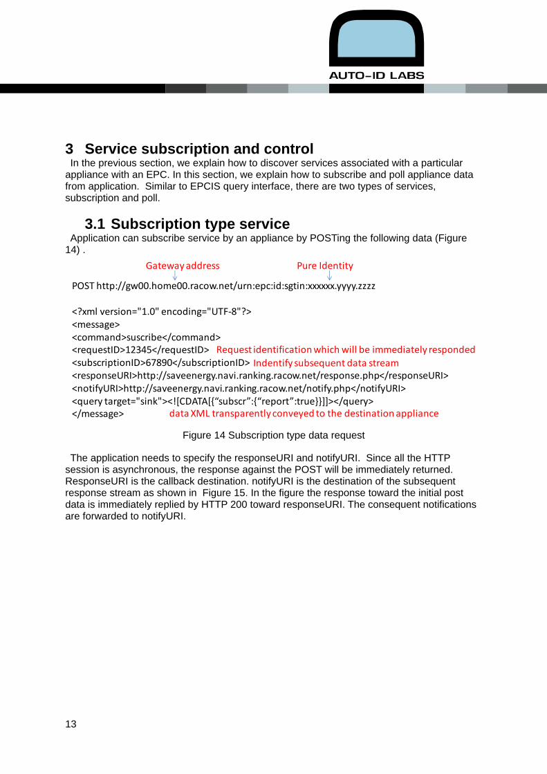
3.1 Subscription type service Application can subscribe service by an appliance by POSTing the following data (Figure
14) .
Figure 14 Subscription type data request
The application needs to specify the responseURI and notifyURI. Since all the HTTP session is asynchronous, the response against the POST will be immediately returned. ResponseURI is the callback destination. notifyURI is the destination of the subsequent response stream as shown in Figure 15. In the figure the response toward the initial post data is immediately replied by HTTP 200 toward responseURI. The consequent notifications are forwarded to notifyURI.
POST http://gw00.home00.racow.net/urn:epc:id:sgtin:xxxxxx.yyyy.zzzz
<?xml version="1.0" encoding="UTF‐8"?><message><command>suscribe</command><requestID>12345</requestID><subscriptionID>67890</subscriptionID><responseURI>http://saveenergy.navi.ranking.racow.net/response.php</responseURI><notifyURI>http://saveenergy.navi.ranking.racow.net/notify.php</notifyURI><query target="sink"><![CDATA[{“subscr”:{“report”:true}}]]></query></message>
Gateway address Pure Identity
Request identification which will be immediately respondedIndentify subsequent data stream
data XML transparently conveyed to the destination appliance

14
Figure 15 Response URI and notify URI
3.2 Poll type service Application can issue poll request by POSTing the following data (Figure 16) . Besides the
command response and the elimination of notifyURI, the poll type sevice are quite similar to subscribe.
Figure 16 Poll type XML
ZigBeeEnd Device
ZigBeeCoordinator Gateway
http: subscribe service by notification
http: Control and EventingTransfer message
Control or Eventing
Report
Transfer report
http: Report
Control point Applications
ZigBee Ethernet EthernetSerial
SensorMCU
UART
Sensor device
responseURI
notifyURI
HTTP 200
POST http://gw00.home00.racow.net/urn:epc:id:sgtin:xxxxxxxxxx.yyyy.zzzz
<?xml version=""1.0"" encoding=""UTF‐8""?><message><command>poll</command><requestID>12345</requestID><responseURI>http://saveenergy.navi.ranking.racow.net/response.php</responseURI><query target="sink"><![CDATA[{“set”:{“lighton”:1}}]]></query></message>
Gateway address Pure Identity
Request identification which will be immediately responded
data XML transparently conveyed to the destination appliance

15
4 Performance evaluation 4.1 Dual interface RF tag
In our implementation of sensor board, ISO18000-6 Type C (Type C hereafter) [14] compatible RF tag chip from Quanray Electronics is used. The chip can use its test ports of the RF tag chip to realize the baseband interface. Because of the direct connection of the test port and the chip lands, the voltage level is lower than commercial MCUs. This is why we have a level convertor to changes voltage between MCU an RF tag chip as shown in Figure 4. The protocol on the baseband interface is the envelop of Type C signal; i.e. no carrier frequency component. Type C inflicts strict timing requirements both to tags and interrogators. Since an MCU plays the role of interrogator, we checked the performance of the MCU against the timing requirement. To relax the requirement toward the MCU, both the forward (from MCU to RF tag) and return (from RF tag to MCU) link speeds are fixed to 40 kbps. We also eliminated the multiple read protocol of Type C and the digital filter which mitigates the out-of-band emission. With these simplifications, the MCU can read an RF tag successfully with in 12.3 msec with a software control. A monitored baseband protocol between an MCU and a dual interface RF tag is shown in Figure 17.
Figure 17 Timing verification of MCU baseband interface
4.2 Sensor board
We first examined APS (application Sublayer) round trip time of ZigBee transceiver. We formed two hop network composed of a sensor device, a router and a coordinator, in an environment where no ZigBee device shares the frequency channel but there are
Commands from MCU
Data from dual interface RF tag
Select Query Ack Req_RN
RN16 EPC (S‐GTIN) handle
12.3msec
16
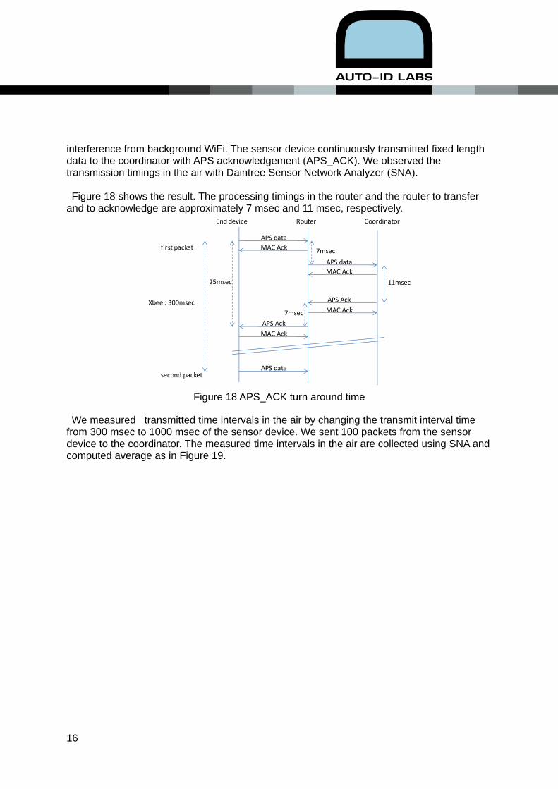
interference from background WiFi. The sensor device continuously transmitted fixed length data to the coordinator with APS acknowledgement (APS_ACK). We observed the transmission timings in the air with Daintree Sensor Network Analyzer (SNA). Figure 18 shows the result. The processing timings in the router and the router to transfer
and to acknowledge are approximately 7 msec and 11 msec, respectively.
Figure 18 APS_ACK turn around time
We measured transmitted time intervals in the air by changing the transmit interval time from 300 msec to 1000 msec of the sensor device. We sent 100 packets from the sensor device to the coordinator. The measured time intervals in the air are collected using SNA and computed average as in Figure 19.
APS data
APS data
MAC Ack
MAC Ack
APS Ack
7msec
11msec
7msecAPS Ack
MAC Ack
MAC Ack
APS data
Xbee : 300msec
End device Router Coordinator
25msec
second packet
first packet

17
Figure 19 Fast reporting interval surges the serial interface
It is shown in Figure 19 that a sensor device cannot transmit consecutive two packets in
less than 300 msec. When we forced to send packets with less than the time interval, the packets starts accumulating in the transmission queue inside the transceiver. Detailed debugging of transmission control firmware in MSP430 revealed that the minimum interval 300 msec matches the whole processing time to send an APS data with XBee through UART with 9600 bps in our implementation. The ideal shortest time duration to send 100 byte data over the UART takes 104 msec (=100 X 10/9600) including one stop and one start bits. Since the UART communications is virtually flow controlled, it is reasonable to take about 300 msec for UART communications. Since we identify the minimum time interval of consecutive two packets is 300 msec, we
define the minimum transmission rate from a single end node is 500 msec with a safety margin of 200 msec. It should be noted that this minimum time interval between two consecutive APS packets
dominates the APS throughput of a single sensor device. Suppose APS maximum payload is 100 Byte1 , the maximum APS throughput from a single sensor device is 1.6 kbps (100 X 8/0.5). We also measured a transit traffic at a ZigBee router. It takes 7 msec to route a packet
meaning that the transit packets is transferred at 115 kbps (100 Byte X 8 bit/ 7 msec) much faster than that of the originating data (Figure 20).
1 ZigBee MAC payload is 127 Byte, subtracting NWK and AUX layer headers yield about 100 Byte for APS

18
Figure 20 Transit packets are faster than originating packets
4.3 Multiple sensor devices throughput performance We set the transmitting interval of each sensor device to be 500 msec not to overload the
transceiver and then increase the number of transmitting sensor device one by one with 5 minutes interval until we observe network congestion. A sensor device is either an end device or a router depending on the route discovery outcome. The subscription of each sensor device were performed by an application by "POST"ing a HTTP message similar to Figure 16. Upon receiving the message from an application, the sensor device reports its sensor data to the gateway in a form of CoAP. The gateway translates the CoAP message to an HTTP message and send it to the destination URL specified by the application. In the experiment, all the report data is stored in a data base (Postgres) with Apache front end. The stored data is analyzed later to evaluate throughput, packet loss and transmission delay. The experiment was done in our office and laboratory. We located the coordinator in our office and all the sensor devices were in laboratory and 4 routers in the middle to form a multi-hop network (Figure 21) in a (612 m^2 = 34m X 18m) working place with steel doors and thick walls.
serial IF
PHY
MAC
NWK
APS
originating packets
transit packets
1.6kbps
144kbps

19
Figure 21 Multiple sensor device throughput evaluation
An APS throughput of a sensor device for a specified network loading is computed by
counting the number of packet received by Postgres data base within the specified time duration. The aggregated APS throughput is computed by summing all APS throughputs considering the number of hops. We can subscribe up to 20 sensor device with 55 aggregated hops achieving about 60 kbps aggregated throughput.
Figure 22 Aggregated throughput
CoordinatorRouter3
Router2
Sensor nodes
laboratory office
Router1
unit (mm)
0
10000
20000
30000
40000
50000
60000
70000
80000
90000
100000
0 10 20 30 40 50 60
Aggregated
throughp
ut (bp
s)
Aggregated number of hops
Ideal aggregated throughput
Measured throughput

20
Up to 14 sensor devices, the aggregated throughput is linear to the number of sensor device, which means there is no traffic congestion in ZigBee network. Since the maximum throughput of a sensor device is 1600 bps, we compute the ideal aggregated through by multiplying 1600 bps and the aggregated number of hops and compared with the measured throughput as shown in Figure 22. It is shown that our implementation is quite close to the ideal throughput up to 16 sensor devices. Since the ideal throughput is dictated by the serial communications between the sensor MCU and transceiver, it is shown that the end-to-end communications are not impeded by UPnP and ZigBee using CoAP.
4.4 Gateway and information system Polling traffic is generated by a multithread Java program and is transmitted to a sensor
device via a gateway. We change the polling time interval from 100 msec to 1000 msec and generated 100 polling requests in each time interval. The performance is measured by counting the number of successfully responded requests, the number of requests rejected by sensor device and the number of request rejected by the gateway. The result is shown in Figure 23. When the polling interval is less than 400 msec, polling requests could be rejected by the gateway. A gateway rejection was counted by observing the response against a polling request. Less than 800 msec time-interval polling requests may be rejected by a sensor device depending on its working load. ZigBee network reveals no problem against this polling traffic because the traffic (1.1 kbps = 100byte x 8 bit/0.7 sec) is far lighter than the maximum aggregated bandwidth (60 kbps).
Figure 23 Rapid polling request may be rejected by gateway
2212
1
20 3549
64
78
92100 100 100 100
58 53 51
36
22
8
0
10
20
30
40
50
60
70
80
90
100
100 200 300 400 500 600 700 800 900 1000
Num
ber o
f packets
Polling interval (msec)
Successful response
Rejected by end device
Rejected by gateway

21
5 Conclusion Consumer electronics (CE) are involved in many services, during their product life cycle, such as manufacturing control, supply chain, home energy management, maintenance, recycle and disposal. Information system based on globally unique ID is a prominent solution to efficiently share information on a CE. Existing ID information system, EPC network, ID are assumed to be retrieved only by interrogator or bar code scanner. This prerequisite unduly limits the inherit benefit of ID information system. Globally unique ID of industrial product shall be retrieved through any access network technology. In order to retrieve ID from appliances in consumer’s premise and discover services associate with the ID, UPnP with a notification of the ID during its JOIN process is developed. When we have a constrained network such as ZigBee segment in consumer premise network, HTTP transport in UPnP and application may result in congestions and delayed response. The use of CoAP over a constrained network realizes end-to-end HTTP communications between application and the CE. In this case, a gateway which takes care of the protocol conversion between HTTP and CoAP is necessary. Unlike existing gateway of home network, our gateway is transparently transfers application packets towards and from appliance and takes care of subscription controls, which is agnostic to applications, for low computational power appliances. Application data is composed of two tiered XML, upper layer for appliances and lower layer for gateways. This way, an introduction of new device or new services can be significantly facilitated because we do not need to update gateways. Fundamental concern of this architecture is the traffic increase particularly in the constrained network. Experimental verification reveals we can collect up to 16 devices whose reporting interval is 0.5 seconds and the aggregated number of hop is 40. This performance is sufficient in general CE applications. If we use board type PC for gateway, large amount of report requests, shorter than every 0.3 sec, to appliances from clients may result in packet loss at the gateway.

22
References [1] http://www.retailresearch.org/grtb_globaltrends.php
[2] Japan Green House Effect Gas Inventory Report, Green house effect gas Inventory Office, (2011), http://www-gio.nies.go.jp/aboutghg/nir/2011/NIR-JPN-2011-v4.0J_web.pdf
[3] CO2 emission from household, Japan Center for Climate Change Action, http://www.jccca.org/chart/chart04_06.html , viewed in Jan.13, 2012
[4] Global and pluggable sensor and actuator networking framework, EC FP7 SENSEI document D.3.2, (2009).
[5] Mik Botts, George Percivall, Carl Reed, John Davidson, Editors, ”OGC Sensor Web Enablement: Overview And High Level Architecture”, OCG 07-165, (2007).
[6] Joachim W. Walewski, Editor, ”Initial Architectural Reference Model for IoT”, EC FP7 IoT-A (257521) D1.2, (2011).
[7] UPnP Device Architecture 1.1, (2008)
[8] Kawamoto, R. Emori, T. Sakata, S. Furuhata, K. Yuasa, K. Hara, S. ”DLNA-ZigBee Gateway Architecture and Energy Efficient Sensor Control for Home Networks,” 16th IST Mobile and Wireless Communications Summit, 1-5 July 2007.
[9] Kuk-Se Kim; Chanmo Park; Kyung-Sik Seo; Il-Yong Chung; Joon Lee, ”ZigBee and The UPnP Expansion for Home Network Electrical Appliance Control on the Internet”, The 9th International Conference on Advanced Communication Technology,vol. 3, (2007), pp.1857-1860.
[10] Seong Hoon Kim, Jeong Seok Kang, Hong Seong Park, Daeyoung Kim, Young-joo Kim,”UPnP-ZigBee internetworking architecture mirroring a multi-hop ZigBee network topology”, IEEE Transactions on Consumer Electronics, vol. 55, Issue 3, (2009), pp.1286-1294.
[11] Hada, et.al.”EPC based Internet of Things Architecture”, IEEE RFID‐TA, September, (2011), pp.519‐524.
[12] Mitsugi, et.al., ”Enabling globally unique Sensor ID with dual‐interface RF tag”, IEEE Sensors, November, (2011), pp.1628‐1631.
[13] Mitsugi, et.al.”Bridging UPnP and ZigBee with CoAP”, ACM CoNext 2011 Workshop on Internet of Things and Service Platforms, (2011).
[14] Mitsugi. J. Towards an Evolving EPCglobal Network Architecture. EPC Technology Forum, April 3, Malaga Spain, 2008.
[15] Sugimoto,K., Mitsugi,J., Nakamura,O., and Murai,J., ”Low power and agile sensor data retrieval using dual interface passive RF tag”, IEEE RFID-TA, 2010, June, pp.100-105.
[16] “Japanese researchers propose recorder tag for extending RFID apps”, Dec.22, 2008, RFID journal.

23
[17] Shelby,Z., Frank,B., and Sturek,D.,”Constrained Application Protocol”, Internet Draft draft-ietfcore-coap, (2010).