Embed Size (px)
Citation preview

E6581871①
TOSVERT VF-S15
Functions for lift application Instruction Manual
E6581871
1
- Contents -
1. Introduction ................................................................................................. 2
2. Functions ..................................................................................................... 2
3. Light –load high-speed operation function ............................................... 3
3.1 Related parameters............................................................................................................ 3
3.2 Mode description............................................................................................................. 4 3.2.1 Automatic setting mode of high-speed operation speed (f328=1, 2) ................ 6 3.2.2 Fixed setting mode of high-speed operation speed (f328=3, 4) ....................... 8
3.3 How to adjust parameters ............................................................................................... 10 3.3.1 Automatic setting mode of high-speed operation speed (f328=1, 2) ............ 10 3.3.2 Fixed setting mode of high-speed operation speed (f328=3, 4) .................... 12 3.3.3 Frequency switching Acceleration/deceleration at light load (f339) ............... 13
4. Brake sequence functions ...................................................................... 14
4.1. Standard connection for lift application ....................................................................... 14
4.2 Parameter adjustment procedure for brake sequence function ................................. 15
4.3 Setting sample of related parameters .................................................. 16
4.4 Brake sequence function ................................................................................................. 18 4.4.1 Parameters for brake sequence functions .............................................................. 19 4.4.2 Execution of "Brake time learning" .......................................................................... 22 4.4.3 Brake timing with maximum load ............................................................................. 23 4.4.4 Abnormal phenomenon and the measures ............................................................. 24
E6581871
2
1. Introduction TOSVERT VF-S15 has effective functions for lift application. This instruction manual explains the light-load high-speed operation function and the brake sequence function of VF-S15 for crane and hoists applications. <Note>
This instruction manual mentions factory specific coefficient parameters.
2. Functions VF-S15 has the following functions for lift application. Use of vector control is based on the execution of brake sequence function or light-load high-speed operation. Therefore, set au2 (Torque boost setting macro function) =2(Vector control + auto-tuning), or set motor related parameters, f410 - f417, and pt (V/F control mode selection) =3(Vector control). 1) Light-load high-speed operation function
This function enhances the operating efficiency of the machine by increasing the rotational speed of the motor in case of light load operation. This function is useful for lifts and material handling applications which repeatedly drive light and heavy loads. The learning function of VF-S15 simplifies the adjustment of light-load high-speed operation, just to execute the forward run (up) or reverse run (down) operation. (f328=3, 4 only)
2) Brake sequence function To ensure smooth operation, the motor produces enough torque before the brake is released.
The learning function for brake timing simplifies rough adjustment of creeping frequency, creeping time and brake release time.
E6581871
3
3. Light –load high-speed operation function
3.1 Related parameters
Title Communication
No. Function Adjustment range
Minimum setting unit
(Panel/ Communication)
Default setting
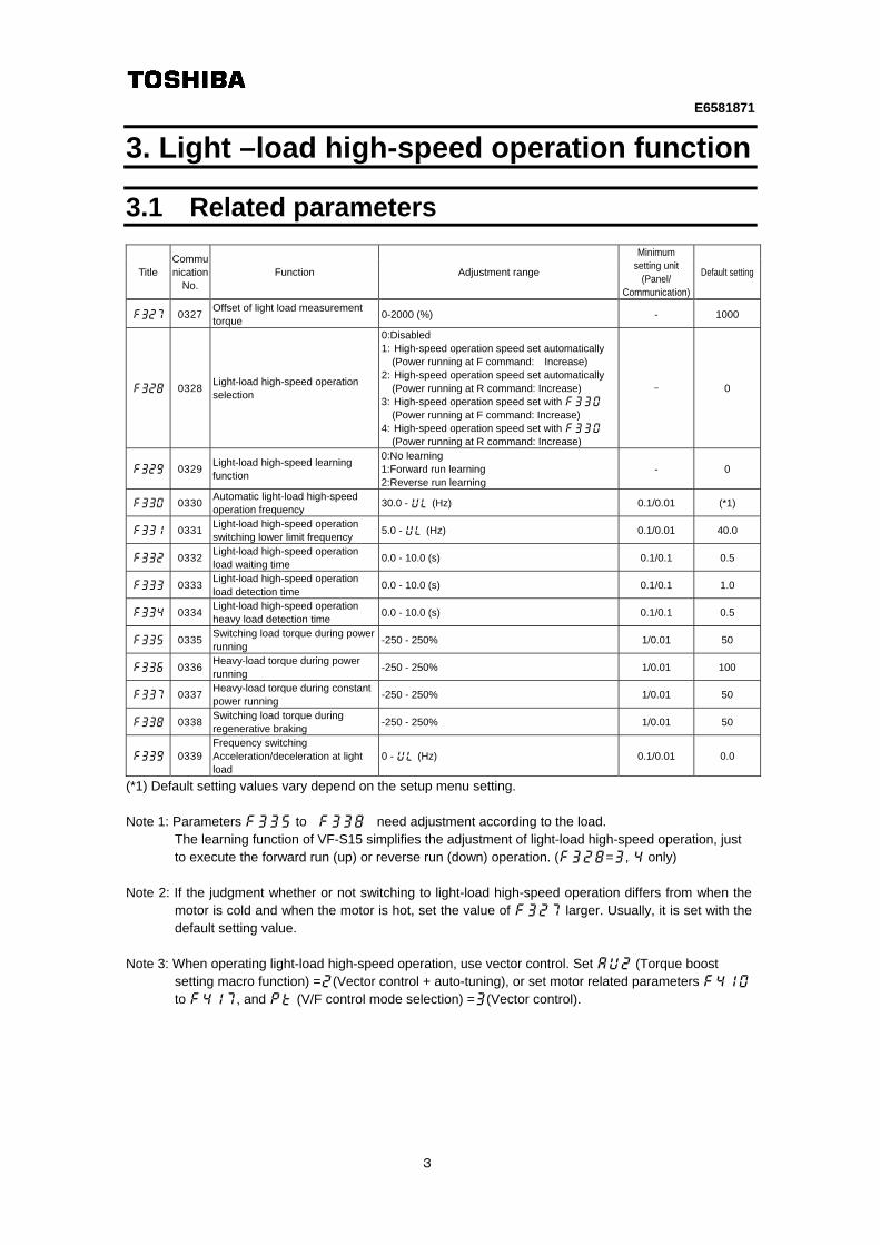
f327 0327 Offset of light load measurement torque
0-2000 (%) - 1000
f328 0328 Light-load high-speed operation selection
0:Disabled 1: High-speed operation speed set automatically
(Power running at F command: Increase) 2: High-speed operation speed set automatically
(Power running at R command: Increase) 3: High-speed operation speed set with f330
(Power running at F command: Increase) 4: High-speed operation speed set with f330
(Power running at R command: Increase)
- 0
f329 0329 Light-load high-speed learning function
0:No learning 1:Forward run learning 2:Reverse run learning
- 0
f330 0330 Automatic light-load high-speed operation frequency
30.0 - ul (Hz) 0.1/0.01 (*1)
f331 0331 Light-load high-speed operation switching lower limit frequency
5.0 - ul (Hz) 0.1/0.01 40.0
f332 0332 Light-load high-speed operation load waiting time
0.0 - 10.0 (s) 0.1/0.1 0.5
f333 0333 Light-load high-speed operation load detection time
0.0 - 10.0 (s) 0.1/0.1 1.0
f334 0334 Light-load high-speed operation heavy load detection time
0.0 - 10.0 (s) 0.1/0.1 0.5
f335 0335 Switching load torque during power running
-250 - 250% 1/0.01 50
f336 0336 Heavy-load torque during power running
-250 - 250% 1/0.01 100
f337 0337 Heavy-load torque during constant power running
-250 - 250% 1/0.01 50
f338 0338 Switching load torque during regenerative braking
-250 - 250% 1/0.01 50
f339 0339 Frequency switching Acceleration/deceleration at light load
0 - ul (Hz) 0.1/0.01 0.0
(*1) Default setting values vary depend on the setup menu setting.
Note 1: Parameters f335 to f338 need adjustment according to the load. The learning function of VF-S15 simplifies the adjustment of light-load high-speed operation, just to execute the forward run (up) or reverse run (down) operation. (f328=3, 4 only)
Note 2: If the judgment whether or not switching to light-load high-speed operation differs from when the
motor is cold and when the motor is hot, set the value of f327 larger. Usually, it is set with the default setting value.
Note 3: When operating light-load high-speed operation, use vector control. Set au2 (Torque boost
setting macro function) =2(Vector control + auto-tuning), or set motor related parameters f410 to f417, and pt (V/F control mode selection) =3(Vector control).

E6581871
4
3.2 Mode description
The light-load high-speed operation includes the modes below: Each mode can be set by the light-load high-speed operation selection (f328).
Title/function Default setting Action
f328
Light-load high-speed operation selection
0: Disabled Light-load high-speed operation disabled.
1:High-speed operation speed set automatically(Power running at F command: Increase)
When inverter judges to be light-load, the high-speed operation frequency is automatically set according to a detected torque.
2:High-speed operation speed set automatically(Power running at R command: Increase) 3:High-speed operation speed set with f330(Power running at F command: Increase)
When inverter judges to be light-load, the operation is set to the automatic light-load high-speed operation frequency (f330).
4:High-speed operation speed set with f330(Power running at R command: Increase)
Example: If automatic setting mode of high-speed operation speed is used,
set f328 to 1 for F (forward command): Up set f328 to 2 for R (reverse command): Up
Note: Light load output and Heavy load output conditions of output terminal functions are different
according to f328 setting.
1) f328 (Light-load high-speed operation selection) =0
Light load output (Function No. 106/107): ON: The absolute value of the detected torque is under the absolute value of f335
(Switching load torque during power running) Light load output (Function No. 164/165):
ON: The absolute value of the detected torque is under the absolute value of f335 (Switching load torque during power running)
Heavy load output (Function No. 108/109): ON: The absolute value of the detected torque is the absolute value of f337 (Heavy-load
torque during constant power running) or more
Note) Function No. 106/107 and No.164/165 are same action when f328=0. Each action is different when f328 setting is not 0.
Function No.108
Function No.164
f335
f335
Torque
Function No.106
0%
f337
f337
E6581871
5
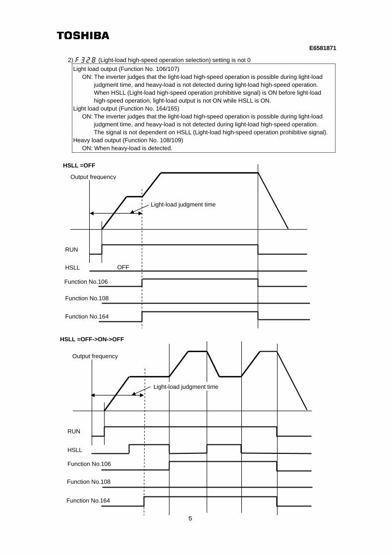
2) f328 (Light-load high-speed operation selection) setting is not 0
Light load output (Function No. 106/107) ON: The inverter judges that the light-load high-speed operation is possible during light-load
judgment time, and heavy-load is not detected during light-load high-speed operation. When HSLL (Light-load high-speed operation prohibitive signal) is ON before light-load high-speed operation, light-load output is not ON while HSLL is ON.
Light load output (Function No. 164/165) ON: The inverter judges that the light-load high-speed operation is possible during light-load
judgment time, and heavy-load is not detected during light-load high-speed operation. The signal is not dependent on HSLL (Light-load high-speed operation prohibitive signal).
Heavy load output (Function No. 108/109) ON: When heavy-load is detected.
Function No.106
Function No.164
Function No.108
Output frequency
HSLL
Light-load judgment time
HSLL =OFF
OFF
RUN
Function No.106
Function No.164
Function No.108
Output frequency
HSLL
Light-load judgment time
HSLL =OFF->ON->OFF
RUN
E6581871
6
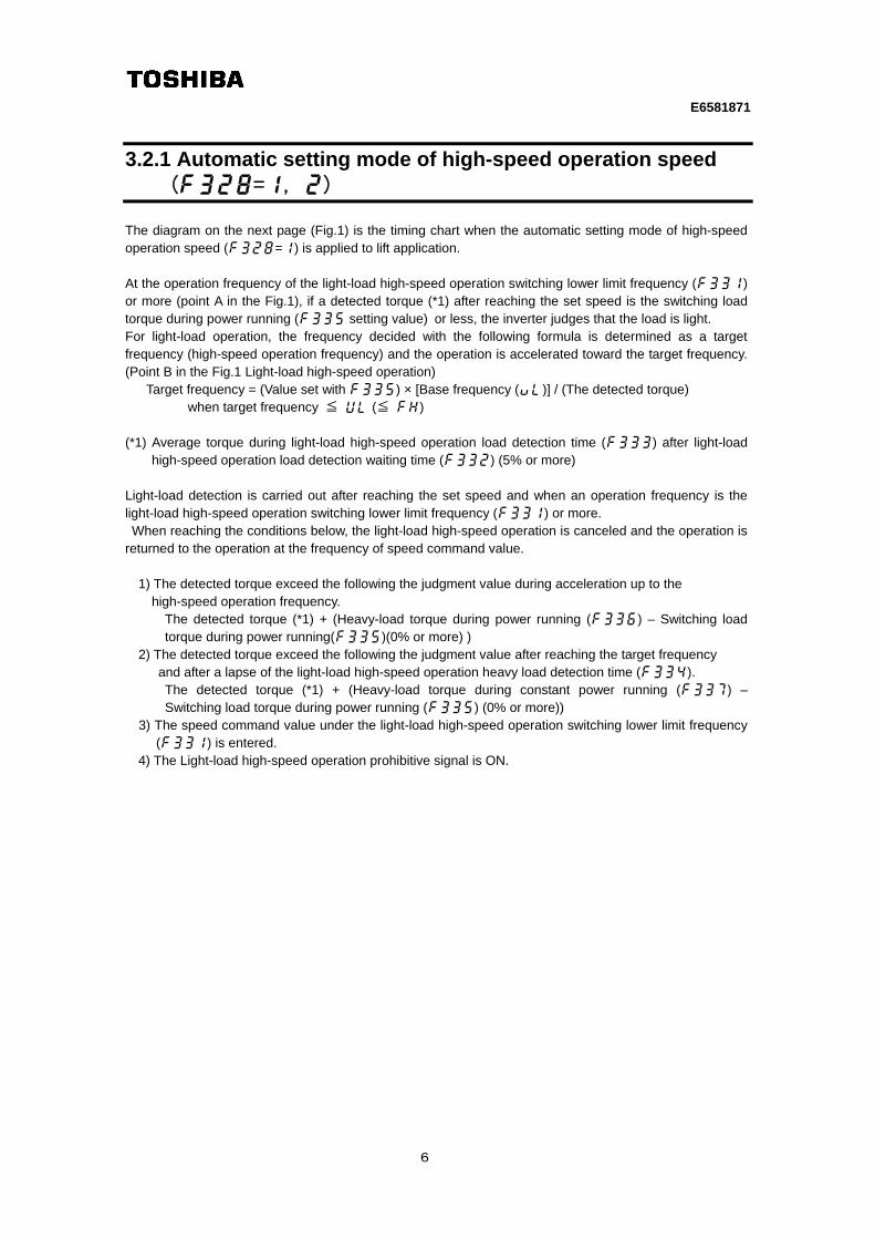
3.2.1 Automatic setting mode of high-speed operation speed (f328=1, 2)
The diagram on the next page (Fig.1) is the timing chart when the automatic setting mode of high-speed operation speed (f328=1) is applied to lift application. At the operation frequency of the light-load high-speed operation switching lower limit frequency (f331) or more (point A in the Fig.1), if a detected torque (*1) after reaching the set speed is the switching load torque during power running (f335 setting value) or less, the inverter judges that the load is light. For light-load operation, the frequency decided with the following formula is determined as a target frequency (high-speed operation frequency) and the operation is accelerated toward the target frequency. (Point B in the Fig.1 Light-load high-speed operation)
Target frequency = (Value set with f335) × [Base frequency (vl)] / (The detected torque) when target frequency ≦ ul (≦ fh)
(*1) Average torque during light-load high-speed operation load detection time (f333) after light-load
high-speed operation load detection waiting time (f332) (5% or more) Light-load detection is carried out after reaching the set speed and when an operation frequency is the light-load high-speed operation switching lower limit frequency (f331) or more. When reaching the conditions below, the light-load high-speed operation is canceled and the operation is returned to the operation at the frequency of speed command value.
1) The detected torque exceed the following the judgment value during acceleration up to the high-speed operation frequency. The detected torque (*1) + (Heavy-load torque during power running (f336) – Switching load
torque during power running(f335)(0% or more) ) 2) The detected torque exceed the following the judgment value after reaching the target frequency
and after a lapse of the light-load high-speed operation heavy load detection time (f334). The detected torque (*1) + (Heavy-load torque during constant power running (f337) –
Switching load torque during power running (f335) (0% or more)) 3) The speed command value under the light-load high-speed operation switching lower limit frequency
(f331) is entered. 4) The Light-load high-speed operation prohibitive signal is ON.
E6581871
7
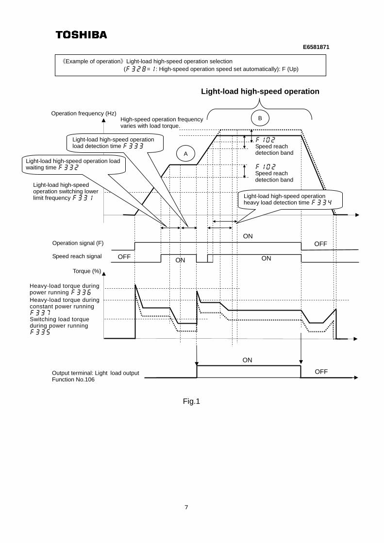
Fig.1
《Example of operation》Light-load high-speed operation selection (f328=1: High-speed operation speed set automatically): F (Up)
Light-load high-speed operation
Heavy-load torque during power running f336
Switching load torque during power running f335
B
Light-load high-speed operation switching lower limit frequency f331
ON
OFF
Torque (%)
A
Output terminal: Light load output Function No.106
Operation frequency (Hz)
Heavy-load torque during constant power running f337
ON
OFF
Operation signal (F)
ON
f102 Speed reach detection band
f102 Speed reach detection band
Light-load high-speed operation load waiting time f332
Light-load high-speed operation load detection time f333
Light-load high-speed operation heavy load detection time f334
High-speed operation frequency varies with load torque.
Speed reach signal
ON
OFF
E6581871
8
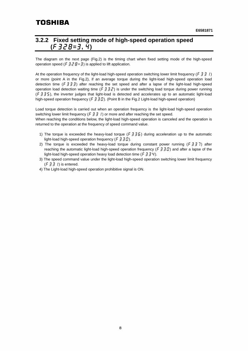
3.2.2 Fixed setting mode of high-speed operation speed (f328=3, 4)
The diagram on the next page (Fig.2) is the timing chart when fixed setting mode of the high-speed operation speed (f328=3) is applied to lift application. At the operation frequency of the light-load high-speed operation switching lower limit frequency (f331) or more (point A in the Fig.2), if an average torque during the light-load high-speed operation load detection time (f333) after reaching the set speed and after a lapse of the light-load high-speed operation load detection waiting time (f332) is under the switching load torque during power running (f335), the inverter judges that light-load is detected and accelerates up to an automatic light-load high-speed operation frequency (f330). (Point B in the Fig.2 Light-load high-speed operation) Load torque detection is carried out when an operation frequency is the light-load high-speed operation switching lower limit frequency (f331) or more and after reaching the set speed. When reaching the conditions below, the light-load high-speed operation is canceled and the operation is returned to the operation at the frequency of speed command value.
1) The torque is exceeded the heavy-load torque (f336) during acceleration up to the automatic light-load high-speed operation frequency (f330).
2) The torque is exceeded the heavy-load torque during constant power running (f337) after reaching the automatic light-load high-speed operation frequency (f330) and after a lapse of the light-load high-speed operation heavy load detection time (f334).
3) The speed command value under the light-load high-speed operation switching lower limit frequency (f331) is entered.
4) The Light-load high-speed operation prohibitive signal is ON.

E6581871
9
Fig.2
《Example of operation》Light-load high-speed operation selection (f328=3: High-speed operation set with f330): F (Up)
Heavy-load torque during constant power running f337
f102 Speed reach detection band
f102 Speed reach detection band
Light-load high-speed operation load waiting time f332
Light-load high-speed operation load detection time f333
Light-load high-speed operation heavy load detection time f334
Automatic light-load high-speed operation frequency f330
Light-load high-speed operation switching lower limit frequency f331
Light-load high-speed operation
ON OFF
ON OFF
Torque (%)
Output terminal: Light load output Function No.106
Operation signal (F)
Heavy-load torque during power running f336
Switching load torque during power running f335
A
B
Speed reach signal
ON
OFF
E6581871
10
3.3 How to adjust parameters
If the light-load high-speed operation is used, be sure to set the motor-related parameters (Motor constants). Refer to Section 6.25 of VF-S15 instruction manual (E6581611) to set motor-related parameters. In addition, for the high-speed operation fixed setting mode (f328=3, 4), learning function simplifies the adjustment of the light-load high-speed operation.
3.3.1 Automatic setting mode of high-speed operation speed (f328=1, 2)
《Adjustment method for lift application》 When the light-load high-speed operation is carried out with normal operation of 60Hz, follow the procedure below:
1) Set the parameter below at an arbitrary position of the status monitor display selection (f711 to
f718). Torque monitor Set value 7 Ex. of LED display q 20
2) Set f328=0 to avoid switching to the light-load high-speed operation.
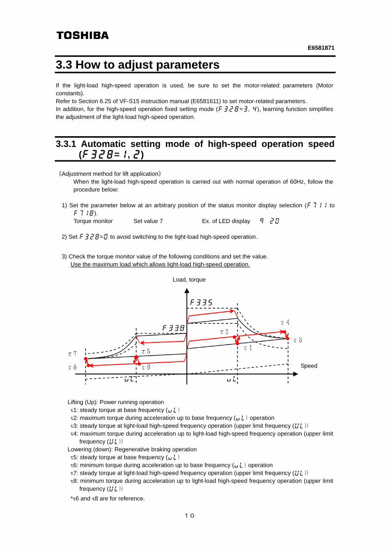
3) Check the torque monitor value of the following conditions and set the value. Use the maximum load which allows light-load high-speed operation.
Lifting (Up): Power running operation τ1: steady torque at base frequency (vl)
τ2: maximum torque during acceleration up to base frequency (vl) operation
τ3: steady torque at light-load high-speed frequency operation (upper limit frequency (ul))
τ4: maximum torque during acceleration up to light-load high-speed frequency operation (upper limit frequency (ul))
Lowering (down): Regenerative braking operation τ5: steady torque at base frequency (vl)
τ6: minimum torque during acceleration up to base frequency (vl) operation
τ7: steady torque at light-load high-speed frequency operation (upper limit frequency (ul))
τ8: minimum torque during acceleration up to light-load high-speed frequency operation (upper limit frequency (ul))
*τ6 and τ8 are for reference.
Load, torque
Speed
E6581871
11
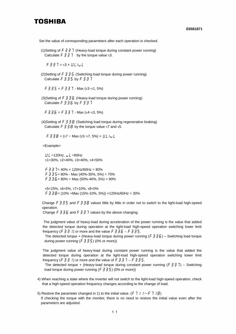
Set the value of corresponding parameters after each operation is checked. (1)Setting of f337 (Heavy-load torque during constant power running)
Calculate f337 by the torque value τ3.
f337 = τ3 × ul/vl
(2)Setting of f335 (Switching load torque during power running) Calculate f335 by f337 f335 = f337 - Max (τ3-τ1, 5%)
(3)Setting of f336 (Heavy-load torque during power running)
Calculate f336 by f337 f336 = f337 - Max (τ4-τ3, 5%)
(4)Setting of f338 (Switching load torque during regenerative braking)
Calculate f338 by the torque value τ7 and τ5.
f338 = (τ7 + Max (τ5-τ7, 5%) × ul/vl
<Example> ul=120Hz, vl=60Hz τ1=30%, τ2=40%, τ3=40%, τ4=50%
f337= 40% × 120Hz/60Hz = 80%
f335= 80% - Max (40%-30%, 5%) = 70%
f336= 80% + Max (50%-40%, 5%) = 90%
τ5=15%, τ6=5%, τ7=10%, τ8=0%
f338= (10% +Max (15%-10%, 5%)) ×120Hz/60Hz = 30%
Change f335 and f338 values little by little in order not to switch to the light-load high-speed operation.
Change f336 and f337 values by the above changing.
The judgment value of heavy-load during acceleration of the power running is the value that added the detected torque during operation at the light-load high-speed operation switching lower limit frequency (f331) or more and the value f336 – f335.
The detected torque + (Heavy-load torque during power running (f336) – Switching load torque during power running (f335) (0% or more))
The judgment value of heavy-load during constant power running is the value that added the detected torque during operation at the light-load high-speed operation switching lower limit frequency (f331) or more and the value of f337 – f335.
The detected torque + (Heavy-load torque during constant power running (f337) – Switching load torque during power running (f335) (0% or more))
4) When reaching a state where the inverter will not switch to the light-load high-speed operation, check
that a high-speed operation frequency changes according to the change of load.
5) Restore the parameter changed in 1) to the initial value. (f711~f718) If checking the torque with the monitor, there is no need to restore the initial value even after the
parameters are adjusted.
E6581871
12
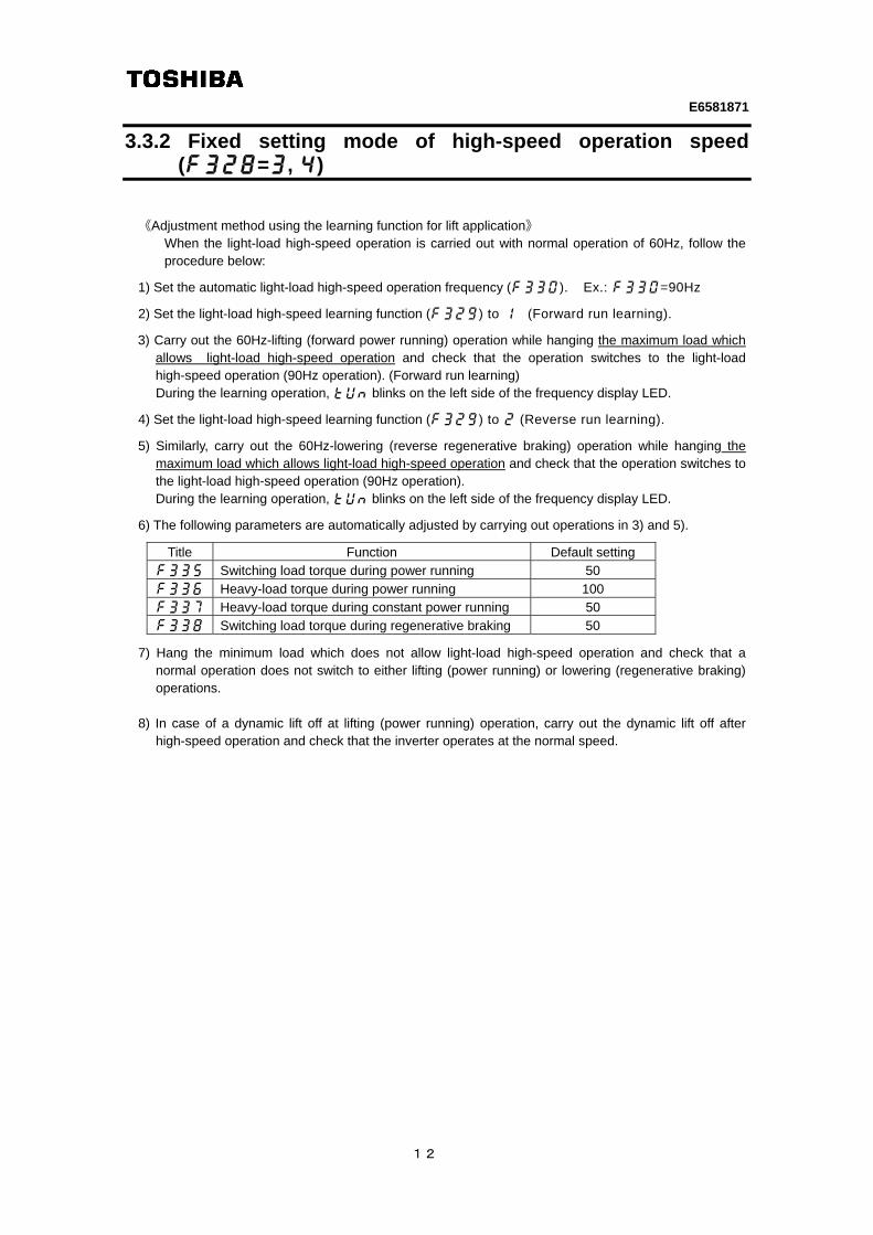
3.3.2 Fixed setting mode of high-speed operation speed (f328=3, 4)
《Adjustment method using the learning function for lift application》 When the light-load high-speed operation is carried out with normal operation of 60Hz, follow the procedure below:
1) Set the automatic light-load high-speed operation frequency (f330). Ex.: f330=90Hz
2) Set the light-load high-speed learning function (f329) to 1 (Forward run learning).
3) Carry out the 60Hz-lifting (forward power running) operation while hanging the maximum load which
allows light-load high-speed operation and check that the operation switches to the light-load high-speed operation (90Hz operation). (Forward run learning) During the learning operation, tun blinks on the left side of the frequency display LED.
4) Set the light-load high-speed learning function (f329) to 2 (Reverse run learning).
5) Similarly, carry out the 60Hz-lowering (reverse regenerative braking) operation while hanging the
maximum load which allows light-load high-speed operation and check that the operation switches to the light-load high-speed operation (90Hz operation). During the learning operation, tun blinks on the left side of the frequency display LED.
6) The following parameters are automatically adjusted by carrying out operations in 3) and 5).
Title Function Default setting
f335 Switching load torque during power running 50 f336 Heavy-load torque during power running 100 f337 Heavy-load torque during constant power running 50 f338 Switching load torque during regenerative braking 50
7) Hang the minimum load which does not allow light-load high-speed operation and check that a
normal operation does not switch to either lifting (power running) or lowering (regenerative braking) operations.
8) In case of a dynamic lift off at lifting (power running) operation, carry out the dynamic lift off after
high-speed operation and check that the inverter operates at the normal speed.
E6581871
13
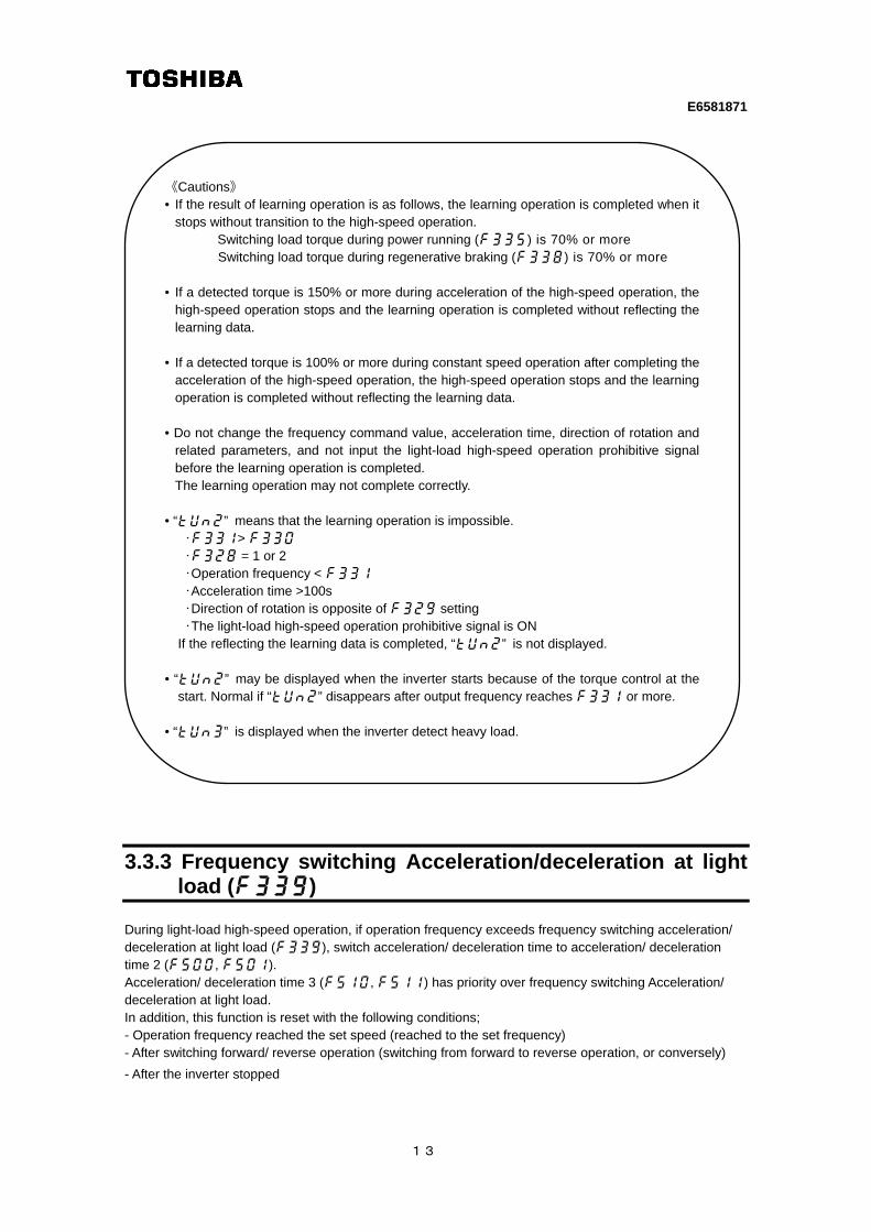
3.3.3 Frequency switching Acceleration/deceleration at light load (f339)
During light-load high-speed operation, if operation frequency exceeds frequency switching acceleration/ deceleration at light load (f339), switch acceleration/ deceleration time to acceleration/ deceleration time 2 (f500, f501). Acceleration/ deceleration time 3 (f510, f511) has priority over frequency switching Acceleration/ deceleration at light load. In addition, this function is reset with the following conditions; - Operation frequency reached the set speed (reached to the set frequency) - After switching forward/ reverse operation (switching from forward to reverse operation, or conversely)
- After the inverter stopped
《Cautions》 • If the result of learning operation is as follows, the learning operation is completed when it
stops without transition to the high-speed operation. Switching load torque during power running (f335) is 70% or more Switching load torque during regenerative braking (f338) is 70% or more
• If a detected torque is 150% or more during acceleration of the high-speed operation, the
high-speed operation stops and the learning operation is completed without reflecting the learning data.
• If a detected torque is 100% or more during constant speed operation after completing the
acceleration of the high-speed operation, the high-speed operation stops and the learning operation is completed without reflecting the learning data.
• Do not change the frequency command value, acceleration time, direction of rotation and
related parameters, and not input the light-load high-speed operation prohibitive signal before the learning operation is completed. The learning operation may not complete correctly.
• “tun2””means that the learning operation is impossible.
・f331> f330
・f328 = 1 or 2
・Operation frequency < f331
・Acceleration time >100s
・Direction of rotation is opposite of f329 setting
・The light-load high-speed operation prohibitive signal is ON
If the reflecting the learning data is completed, “tun2””is not displayed. • “tun2””may be displayed when the inverter starts because of the torque control at the
start. Normal if “tun2” disappears after output frequency reaches f331 or more. • “tun3””is displayed when the inverter detect heavy load.
E6581871
14
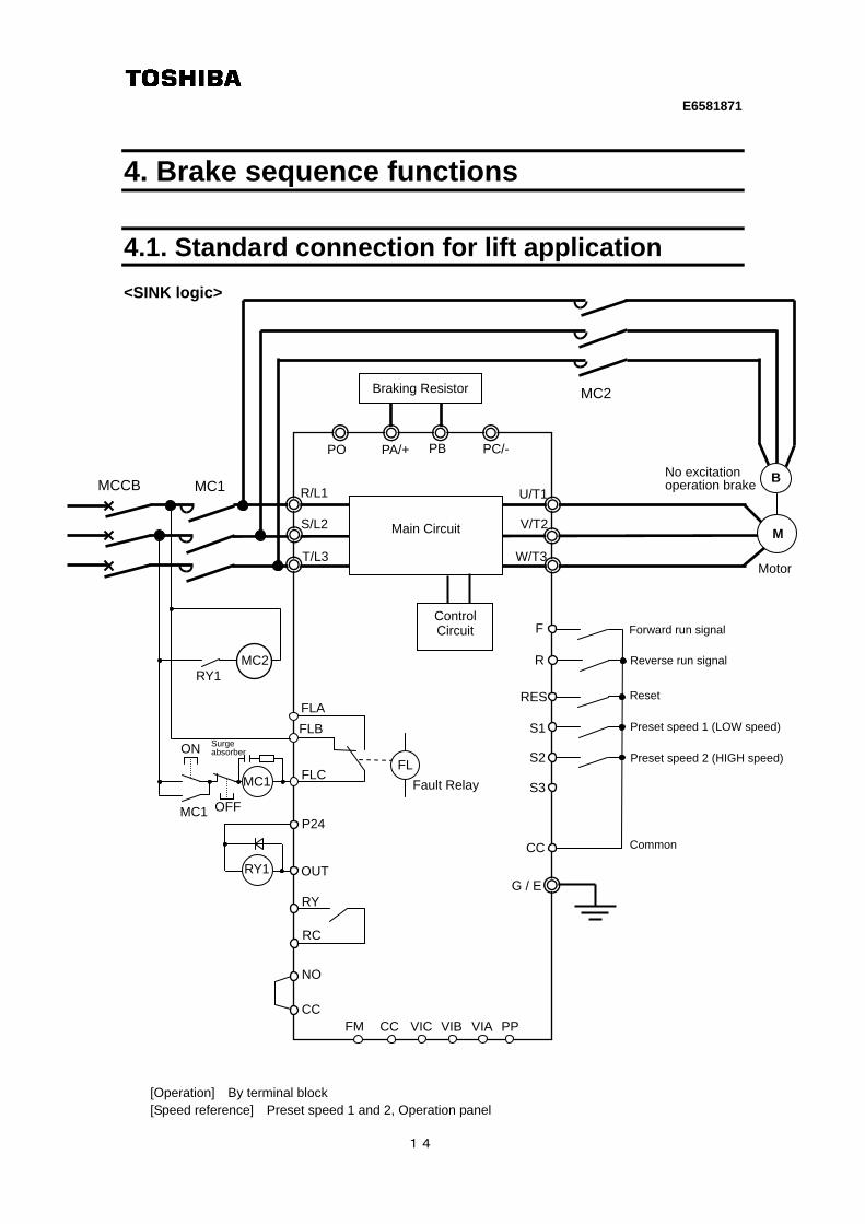
4. Brake sequence functions
4.1. Standard connection for lift application <SINK logic>
[Operation] By terminal block [Speed reference] Preset speed 1 and 2, Operation panel
Motor
FL
G / E
F
RES
CC
R/L1
S/L2
T/L3
U/T1
V/T2
W/T3
FLC
FLB
FLA
Forward run signal
S1
R
S2
S3
RY
P24
OUT
PA/+ PC/-PB PO
Main Circuit
Reset
Preset speed 2 (HIGH speed)
MCCB MC1
M
RY1
Fault Relay
Common
NO
CC
No excitation operation brake
B
Control Circuit
MC2
Reverse run signal
Preset speed 1 (LOW speed)
Braking Resistor
FM CC VIC VIB VIA PP
MC1
OFF
ON
MC1
Surge absorber
MC2 RY1
RC
MC1
E6581871
15
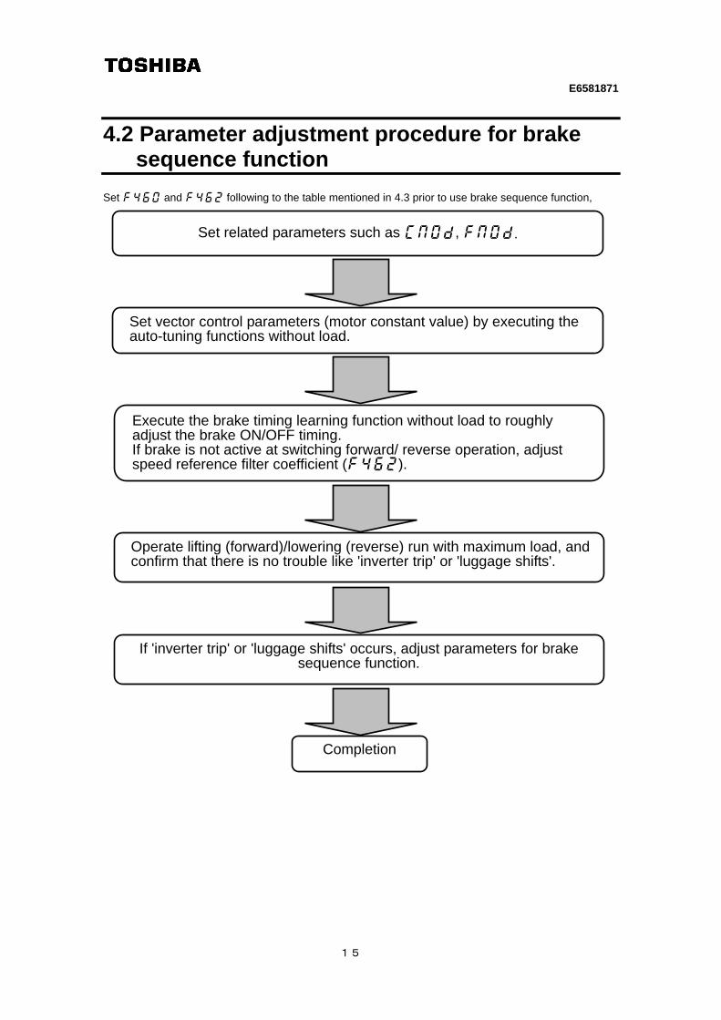
4.2 Parameter adjustment procedure for brake sequence function
Set f460 and f462 following to the table mentioned in 4.3 prior to use brake sequence function,
Set related parameters such as cmod, fmod.
Set vector control parameters (motor constant value) by executing the auto-tuning functions without load.
Execute the brake timing learning function without load to roughly adjust the brake ON/OFF timing. If brake is not active at switching forward/ reverse operation, adjust speed reference filter coefficient (f462).
Operate lifting (forward)/lowering (reverse) run with maximum load, and confirm that there is no trouble like 'inverter trip' or 'luggage shifts'.
If 'inverter trip' or 'luggage shifts' occurs, adjust parameters for brake sequence function.
Completion
E6581871
16
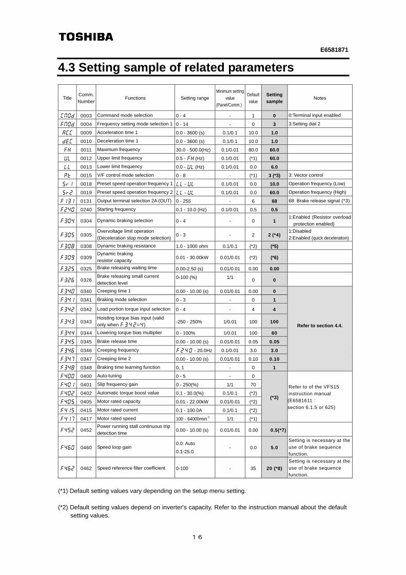
4.3 Setting sample of related parameters
Title Comm.
Number Functions Setting range
Minimum setting
value
(Panel/Comm.)
Default
value
Setting
sampleNotes
cmod 0003 Command mode selection 0 - 4 - 1 0 0:Terminal input enabled
fmod 0004 Frequency setting mode selection 1 0 - 14 - 0 3 3:Setting dial 2
acc 0009 Acceleration time 1 0.0 - 3600 (s) 0.1/0.1 10.0 1.0
dec 0010 Deceleration time 1 0.0 - 3600 (s) 0.1/0.1 10.0 1.0
fh 0011 Maximum frequency 30.0 - 500.0(Hz) 0.1/0.01 80.0 60.0
ul 0012 Upper limit frequency 0.5 - fh (Hz) 0.1/0.01 (*1) 60.0
ll 0013 Lower limit frequency 0.0 - ul (Hz) 0.1/0.01 0.0 6.0
pt 0015 V/F control mode selection 0 - 8 - (*1) 3 (*3) 3: Vector control
sr1 0018 Preset speed operation frequency 1 ll - ul 0.1/0.01 0.0 10.0 Operation frequency (Low)
sr2 0019 Preset speed operation frequency 2 ll - ul 0.1/0.01 0.0 60.0 Operation frequency (High)
f131 0131 Output terminal selection 2A (OUT) 0 - 255 - 6 68 68: Brake release signal (*3)
f240 0240 Starting frequency 0.1 - 10.0 (Hz) 0.1/0.01 0.5 0.5
f304 0304 Dynamic braking selection 0 - 4 - 0 1 1:Enabled (Resistor overload
protection enabled)
f305 0305 Overvoltage limit operation
(Deceleration stop mode selection)0 - 3 - 2 2 (*4)
1:Disabled
2:Enabled (quick deceleration)
f308 0308 Dynamic braking resistance 1.0 - 1000 ohm 0.1/0.1 (*2) (*5)
f309 0309 Dynamic braking
resistor capacity 0.01 - 30.00kW 0.01/0.01 (*2) (*6)
f325 0325 Brake releasing waiting time 0.00-2.50 (s) 0.01/0.01 0.00 0.00
f326 0326 Brake releasing small current
detection level 0-100 (%) 1/1
0 0
f340 0340 Creeping time 1 0.00 - 10.00 (s) 0.01/0.01 0.00 0
Refer to section 4.4.
f341 0341 Braking mode selection 0 - 3 - 0 1
f342 0342 Load portion torque input selection 0 - 4 - 4 4
f343 0343 Hoisting torque bias input (valid
only when f342=4) -250 - 250% 1/0.01 100 100
f344 0344 Lowering torque bias multiplier 0 - 100% 1/0.01 100 60
f345 0345 Brake release time 0.00 - 10.00 (s) 0.01/0.01 0.05 0.05
f346 0346 Creeping frequency f240 - 20.0Hz 0.1/0.01 3.0 3.0
f347 0347 Creeping time 2 0.00 - 10.00 (s) 0.01/0.01 0.10 0.10
f348 0348 Braking time learning function 0, 1 - 0 1
f400 0400 Auto-tuning 0 - 5 - 0
(*3)
Refer to of the VFS15
instruction manual
(E6581611 :
section 6.1.5 or 625)
f401 0401 Slip frequency gain 0 - 250(%) 1/1 70
f402 0402 Automatic torque boost value 0.1 - 30.0(%) 0.1/0.1 (*2)
f405 0405 Motor rated capacity 0.01 - 22.00kW 0.01/0.01 (*2)
f415 0415 Motor rated current 0.1 - 100.0A 0.1/0.1 (*2)
f417 0417 Motor rated speed 100 - 64000min-1 1/1 (*1)
f452 0452 Power running stall continuous trip
detection time 0.00 - 10.00 (s) 0.01/0.01 0.00 0.5(*7)
f460 0460 Speed loop gain 0.0: Auto
0.1-25.0 - 0.0 5.0
Setting is necessary at the
use of brake sequence
function.
f462 0462 Speed reference filter coefficient 0-100 - 35 20 (*8)
Setting is necessary at the
use of brake sequence
function.
(*1) Default setting values vary depending on the setup menu setting. (*2) Default setting values depend on inverter's capacity. Refer to the instruction manual about the default
setting values.
E6581871
17
(*3) Select the vector control in case of using brake sequence functions (output terminal functions: 68, 69).
Set au2 (Torque boost setting macro function) =2 (vector control + auto-tuning), or set motor constant parameters (f401 to f417) and pt (V/F control mode selection) =3 (vector control)
(*4) f304 (Dynamic braking selection) =1 to4 (Enabled) setting will process automatically as same as f305 (Overvoltage limit operation) =1 (Disabled).
(*5) The braking resistor with the value smaller than the minimum allowable resistance value cannot be
connected. (*6) Set the resistance capacity suitable for specifications of connected braking resistor's capacity. (*7) This is one of the fall prevention functions of lift application. If the stall prevention function continues,
the inverter judges that the motor has stalled and trips. Set the detection time to about 0.5 seconds. (*8) If brake is not active when switching forward/ reverse, set the value of Speed reference filter
coefficient (f462) smaller little by little.
E6581871
18
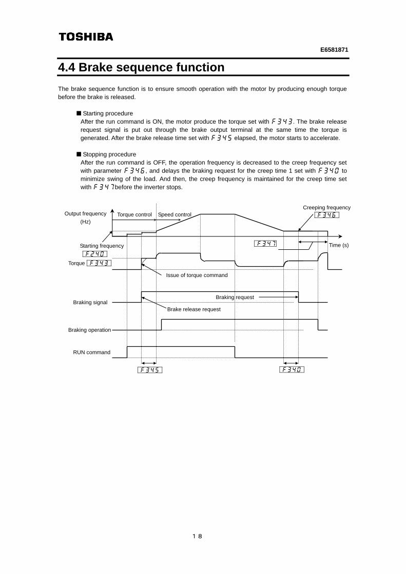
4.4 Brake sequence function The brake sequence function is to ensure smooth operation with the motor by producing enough torque before the brake is released.
Starting procedure After the run command is ON, the motor produce the torque set with f343. The brake release request signal is put out through the brake output terminal at the same time the torque is generated. After the brake release time set with f345 elapsed, the motor starts to accelerate.
Stopping procedure
After the run command is OFF, the operation frequency is decreased to the creep frequency set with parameter f346, and delays the braking request for the creep time 1 set with f340 to minimize swing of the load. And then, the creep frequency is maintained for the creep time set with f347before the inverter stops.
Output frequency
(Hz)
Torque
Braking signal
RUN command
Time (s)
Torque control Speed control
Braking request
Brake release request
Issue of torque command
Creeping frequency
Starting frequency
Braking operation
E6581871
19
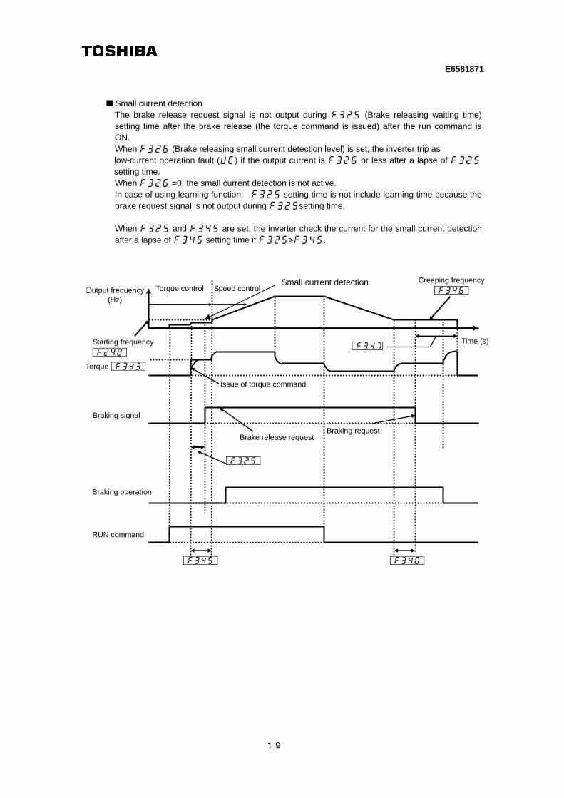
Small current detection The brake release request signal is not output during f325 (Brake releasing waiting time) setting time after the brake release (the torque command is issued) after the run command is ON.
When f326 (Brake releasing small current detection level) is set, the inverter trip as low-current operation fault (uc) if the output current is f326 or less after a lapse of f325 setting time. When f326 =0, the small current detection is not active.
In case of using learning function, f325 setting time is not include learning time because the brake request signal is not output during f325setting time.
When f325 and f345 are set, the inverter check the current for the small current detection
after a lapse of f345 setting time if f325>f345.
Output frequency (Hz)
Torque
Braking signal
RUN command
Time (s)
Torque control Speed control
Braking request Brake release request
Issue of torque command
Creeping frequency
Starting frequency
Braking operation
Small current detection
E6581871
20
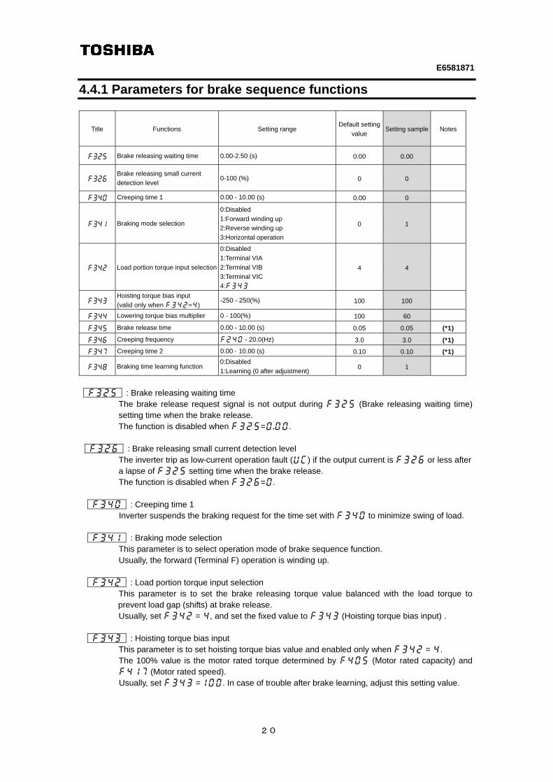
4.4.1 Parameters for brake sequence functions
Title Functions Setting range Default setting
value Setting sample Notes
f325 Brake releasing waiting time 0.00-2.50 (s) 0.00 0.00
f326 Brake releasing small current
detection level 0-100 (%) 0 0
f340 Creeping time 1 0.00 - 10.00 (s) 0.00 0
f341 Braking mode selection
0:Disabled
1:Forward winding up
2:Reverse winding up
3:Horizontal operation
0 1
f342 Load portion torque input selection
0:Disabled
1:Terminal VIA
2:Terminal VIB
3:Terminal VIC
4:f343
4 4
f343 Hoisting torque bias input
(valid only when f342=4) -250 - 250(%) 100 100
f344 Lowering torque bias multiplier 0 - 100(%) 100 60
f345 Brake release time 0.00 - 10.00 (s) 0.05 0.05 (*1)
f346 Creeping frequency f240 - 20.0(Hz) 3.0 3.0 (*1)
f347 Creeping time 2 0.00 - 10.00 (s) 0.10 0.10 (*1)
f348 Braking time learning function 0:Disabled
1:Learning (0 after adjustment) 0 1
f325 : Brake releasing waiting time
The brake release request signal is not output during f325 (Brake releasing waiting time) setting time when the brake release. The function is disabled when f325=0.00.
f326 : Brake releasing small current detection level
The inverter trip as low-current operation fault (uc) if the output current is f326 or less after a lapse of f325 setting time when the brake release. The function is disabled when f326=0.
f340 : Creeping time 1
Inverter suspends the braking request for the time set with f340 to minimize swing of load. f341 : Braking mode selection This parameter is to select operation mode of brake sequence function. Usually, the forward (Terminal F) operation is winding up. f342 : Load portion torque input selection
This parameter is to set the brake releasing torque value balanced with the load torque to prevent load gap (shifts) at brake release.
Usually, set f342 = 4, and set the fixed value to f343 (Hoisting torque bias input) . f343 : Hoisting torque bias input This parameter is to set hoisting torque bias value and enabled only when f342 = 4.
The 100% value is the motor rated torque determined by f405 (Motor rated capacity) and f417 (Motor rated speed). Usually, set f343 =100. In case of trouble after brake learning, adjust this setting value.
E6581871
21
f344 : Lowering torque bias multiplier
The torque bias value at brake release is set by f342 (Load portion torque input selection). When winding down, the torque bias value is multiplied by this parameter value. Usually, a necessary torque in winding down is decreased by squaring the mechanical efficiency. The hoisting torque bias in winding down at 80% machine efficiency is 0.8*0.8=0.64 (about 60%). Usually, set f344 = 60 to 70.
f345 : Brake release time The brake release request signal is output at the same time outputting the set torque after the
starting signal is turned on. After the time set with f345 (Brake release time), the inverter accelerates. (*1)This parameter is roughly adjusted by executing f348 (Braking time learning function).
f346 : Creeping frequency
After run command is OFF, braking request is put out after decelerated to f346 (Creep frequency). A standard setting of the creep frequency is about motor rated slips. For example, in case of 5% slips in 60Hz motor, the creeping frequency is "60Hz*5%=3Hz".
(*1)This parameter is roughly adjusted by executing f348 (Braking time learning function) .
f347 : Creeping time 2
After run command is OF, braking request is put out after decelerated to f346 (Creep frequency). Then, the creeping frequency is maintained for the time set with f347 (Creeping time 2). (*1)This parameter is roughly adjusted by executing f348 (Braking time learning function)
f348 : Braking time learning function
The brake learning function is executed by forward winding up operation after setting f348 (Braking time learning function) to 1. Braking time learning function roughly adjusts the parameters f345 (Brake release time), f346 (Creeping frequency), and f347 (Creeping time 2).
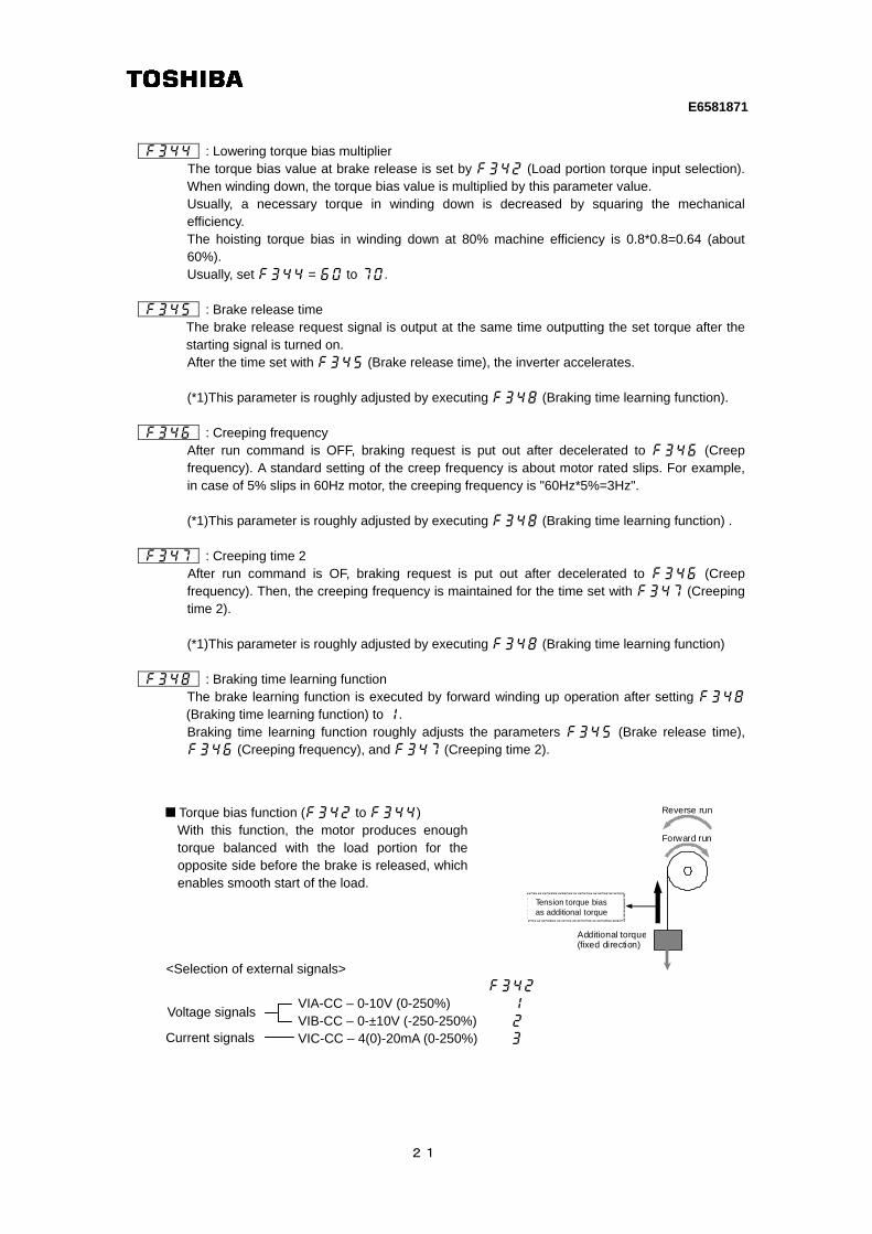
Torque bias function (f342 to f344)
With this function, the motor produces enoughtorque balanced with the load portion for the opposite side before the brake is released, which enables smooth start of the load.
Additional torque (fixed direction)
Reverse run
Forward run
Tension torque bias as additional torque
VIA-CC – 0-10V (0-250%) 1
VIB-CC – 0-±10V (-250-250%) 2
VIC-CC – 4(0)-20mA (0-250%)
<Selection of external signals>
Voltage signals
Current signals
E6581871
22
4.4.2 Execution of "Brake time learning"
Learning function (f348) This function roughly adjusts the parameters f345, f346, and f347 automatically. If necessary, fine adjust the parameter setting manually.
Learning operation Set parameter f348 to 1 and enter an operation command to start learning. The frequency and “tun” are displayed alternately. Parameter f343 (torque) is set, the brake release timing is calculated, and parameter f345 (release time) is set based on the calculation result. f346 is calculated and set automatically based on the motor constant. At the stop of operation, f347 (creep time) is set. Note 1: Learning should be performed under light-load conditions. Note 2: If a counterweight is provided, a learning error may occur. If so, make an adjustment
manually. Note 3: Brake learning should be carried out for forward rotation if f341 is set to 1
(forward winding), or for reverse rotation if f341 is set to 2 (reverse winding).
《Notice for brake sequence function》 Note 4: For the brake sequence functions, the pre-excitation time is automatically determined
by the inverter from motor-related constants. When the VFS15S-2022PL-W is used in combination with a Toshiba 4P-2.2kW-60Hz-200V standard motor, the pre-excitation time is approximately 0.1 to 0.2 seconds. Depending on the motor, the pre-excitation time may be prolonged.
Note 5: Select the vector control in case of using brake sequence functions. Set f460 and f462 following to the tables described in 4.3. Set au2 (Torque boost setting macro function) =2 (vector control + auto-tuning) or set motor constant parameters (f401f to 417) and pt (V/F control mode selection) =3 (vector control).
Note 6: For checking the inverter operation by brake sequence functions, be sure to connect and run the combined motor.
As this function calculates the brake timing by detecting output current, calculation error occurs without connecting the motor.
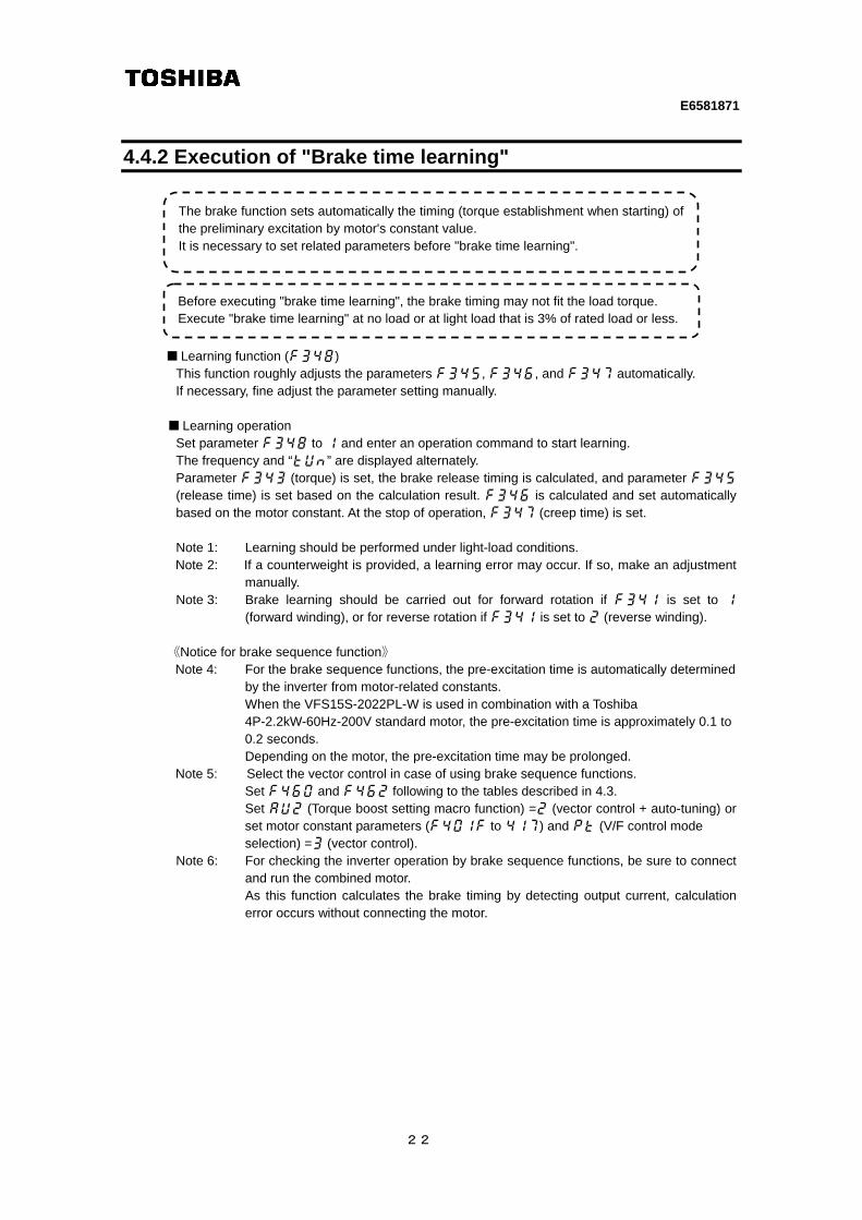
The brake function sets automatically the timing (torque establishment when starting) of the preliminary excitation by motor's constant value. It is necessary to set related parameters before "brake time learning".
Before executing "brake time learning", the brake timing may not fit the load torque. Execute "brake time learning" at no load or at light load that is 3% of rated load or less.

E6581871
23
4.4.3 Brake timing with maximum load Confirm if there is any problem with brake timing with maximum load after completion of adjustment of brake timing at no-load (light load). Please confirm the following items;
- Whether or not brake is released smoothly without load gap (shifts) at winding up or starting - With our without load gap (shifts) when the brake operates? - With or without load gap (shifts) when repeating start (run/stop)? - With or without unusual noise from the brake at the time of start and stop. - With or without the inverter trip at the time of start or stop.
If there is no trouble after confirmation, an adjustment of the brake function is completed. 《Useful function for adjustment》 Timing adjustment to release brake at the same time with gaining enough torque and stop after the brake is completely closed are required for lift application. Therefore, the motor is restrained to some degree at start/stop. Short restrained time may cause load gap (shifts). But, long restrained time increases motor current, which will cause the inverter trip. Please use the following parameters for adjustment to confirm a peak output current. Usually, a peak output current is about 150% of inverter's rated current.
Title Function Setting range
Default
setting
value
Setting
sample Notes
f709 Standard monitor hold function
0:Real time
1:Peak hold
2:Minimum hold
0 1 -
f710 Initial panel display selection 0 - 52 0 1 Output current
f750 EASY key function selection
0:Easy/standard setting mode
switching function
1:Shortcut key
2:Local/remote key
3:Monitor peak /minimum hold trigger
4: -
5: -
0 3 -
The status monitor display shows "Peak hold value of output current" by the above parameter settings. Display changes as the peak value of the output current changes by repeating start/stop. This value is forcibly reset by pushing the "EASY" key.
E6581871
24
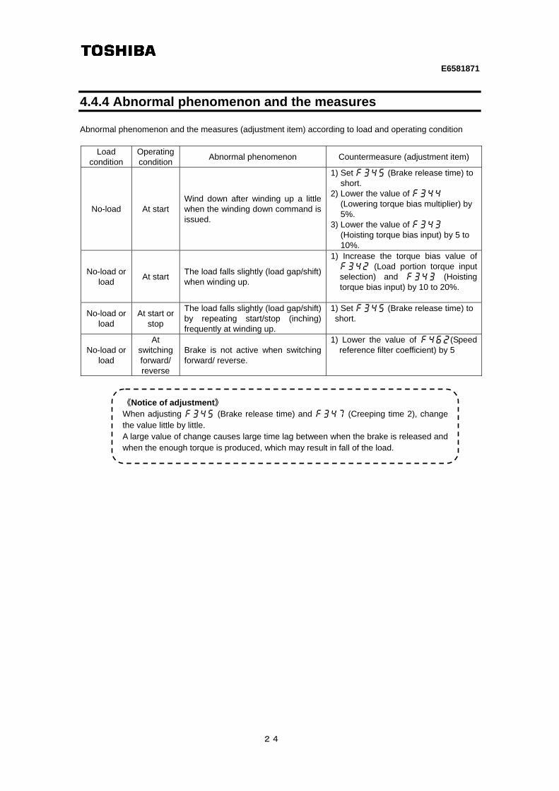
4.4.4 Abnormal phenomenon and the measures Abnormal phenomenon and the measures (adjustment item) according to load and operating condition
Load condition
Operating condition
Abnormal phenomenon Countermeasure (adjustment item)
No-load At start Wind down after winding up a little when the winding down command is issued.
1) Set f345 (Brake release time) to short.
2) Lower the value of f344 (Lowering torque bias multiplier) by 5%.
3) Lower the value of f343 (Hoisting torque bias input) by 5 to 10%.
No-load or load
At start The load falls slightly (load gap/shift)when winding up.
1) Increase the torque bias value of f342 (Load portion torque input selection) and f343 (Hoisting torque bias input) by 10 to 20%.
No-load or load
At start or stop
The load falls slightly (load gap/shift) by repeating start/stop (inching) frequently at winding up.
1) Set f345 (Brake release time) to short.
No-load or load
At switching forward/ reverse
Brake is not active when switching forward/ reverse.
1) Lower the value of f462(Speed reference filter coefficient) by 5
《Notice of adjustment》 When adjusting f345 (Brake release time) and f347 (Creeping time 2), change the value little by little. A large value of change causes large time lag between when the brake is released and when the enough torque is produced, which may result in fall of the load.