Embed Size (px)
Citation preview

#Z43848E-2
User’s Manual
Product
SHAN5 Version 1.12 (V Series Servo Amplifier PC Tool)
Model
SFV02
July2005
TOSHIBA MACHINE CO., LTD.

#Z43848E-2
1
Introduction
This document describes the operation and installation methods of the PC tool SHAN5 for V-Series servo amplifiers.
Note: The specifications of SHAN5 may be changed without a prior notice. Some screen shots in this document may be slightly different from the corresponding actual screens depending on your software version.
Table of Contents Page
1. Overview 1-1. Main Functions 1-2. Operation Environment 1-3. Installation Method 1-4. Screen Names and Functions
2. How to Use Each Functional Screen 2-1. Main Menu Monitor Display Screen 2-2. Environment Screen 2-3. Edit Parameter Screen 2-4. Transfer Parameter Screen 2-5. Sampling Condition Screen 2-6. Frequency Analyze Condition Screen 2-7. Remote Drive Screen (Tuning Function) 2-8. Tuning Items and Steps 2-8-1. Tuning Mode Select Screen 2-8-2. Tuning Semi-Auto Mode Screen 2-8-3. Tuning Real-Time Mode Screen 2-8-4. Tuning Manual Mode Screen 2-8-5. Tuning Gain Setup Screen 2-8-6. Tuning Filter Setup Screen 2-8-7. TFC (Twin Freedom Control) Setup Screen (Sub-monitor screen) 2-9. Amp Information Screen 2-10. Real Alarm Screen 2-11. Alarm History Screen 2-12. Version Display Screen
3. Additional Information 3-1. Alarm (Detective Conditions and Solutions) 3-2. About HELP
#Z43848E-2
2
1. Overview
This section describes the main functions, working environment, installation method, and screen composition of SHAN5.
1-1. Main Functions
SHAN5 has the following major functions:
* Monitoring V Series servo amplifier operational statuses (motor rotation rates, current values, commands, etc.) * Editing and transferring parameters * Waveform display function for measuring velocity and current waveforms * Frequency analyze function for measuring and displaying power spectra of velocity and current waveforms * Remote drive function * Tuning function
1-2. Operation Environment
PC hardware and software requirements are as following:
* CPU: Pentium 133 MHz or higher (recommended) * Memory: 32 MB or more (recommended) * Compatible operating system Windows 95 (Note: Not compatible with early versions and A version) Windows 98 (including the Second Edition) Windows Me Windows 2000 Compatibility test has not been conducted with Windows NT.
* Display monitor Resolution: 1024 x 768 or 1028 x 1024 or higher (recommended)
Note: See “2-2. Environment screen” for changing serial ports and RS232C baud rates.

#Z43848E-2
3
1-3. Installation Method
Click the “Setup.exe” file in the “SHAN5” folder in the CD-ROM. The SHAN5 InstallShield wizard screen (Fig. 1-3-1) will open.
Fig. 1-3-1. SHAN5 InstallShield Wizard Startup Screen
Install SHAN5 following the instructions on the displayed screens.

#Z43848E-2
4
1-4. Screen Names and Functions
SHAN5 has the following screens with the described functions.
Screen No. Screen name Functions 000 Main Menu Monitor screen * Startup interface
* Servo amplifier monitoring * Command buttons for opening Parameter Edit screen and Parameter
Transfer screen 001 Environment screen * Settings of serial ports and communication baud rates may be
changed. 010 Amplifier status screen * Amplifier operational conditions such as axis numbers, optional
statuses, servo-lock missing conditions, and warnings are displayed. 020 Real Alarm screen * Up to eight ongoing alarms are displayed.
Alarm numbers, messages, as well as individual alarm detecting conditions and possible workarounds are shown.
030 Alarm History screen * The latest alarm events are listed up to sixteen entries. You may also clear or save in a file alarm events from a history.
040 Version Status screen * Information such as the servo amplifier CPU version is displayed. 050 Option I/O screen
(Mode 11 and 12 only) * Option I/O is enabled in the control modes 11 and 12.
Option input range from 10 to 27 and output range from 10 to 17 060 Option I/O screen
(Mode 21 and 24 only) * Option I/O is enabled in the control modes 21 through 24.
Option input range from 10 to 5F and output range from 10 to 5F 100 Edit Parameter screen * User, Analog adjustment, Tuning, and other parameters may be edited.
PTP parameters and point data also may be edited for “NCBOY-64.” Editing objects may be switched using “Standard Amp” or
“NCBOY-64” on the Select Editing Object screen. 110 Edit Point Data screen * Point data entries from 0 through 63 may be edited. 120 Select Editing Object screen * Parameter editing objects may be changed in this screen.
User, analog adjustment, and tuning parameters may be edited when “Standard Amplifier” is selected.
User, analog adjustment, tuning, and PTP parameters and point data may be edited when “NCBOY-64” is selected.
200 Transfer Parameter screen * You may transfer parameters to the servo amplifier from this screen. 300 Sampling Condition screen * Sampling condition may be set in this screen.
Measurement items on Channels 1 through 4, sampling intervals, trigger conditions may be set.
310 Sampling Graphics screen * Sampling results are displayed in graphic charts on this screen. 320 Sampling Graphics Setup
screen * Line colors and sizes of graphs and background colors on the
Sampling Graphics screen may be changed on this screen. 400 Frequency Analyze
Condition screen * Measurement conditions for frequency analysis are set on this screen. You may set measurement items, oscillating frequencies, oscillating waveforms, etc. for Channel 1 and 2.
410 Frequency Analyze Graphics screen
* Measurement results for frequency analysis are set on this screen. Measurement results are displayed in four types: Timing Display, Power Spectrum, Frequency Response, or Response Summary.
420 Sampling Graphics Setup screen
* Line colors and sizes of graphs and background colors on the Sampling Graphics screen may be changed on this screen. Fig. 1-4-1 Screen List 1

#Z43848E-2
5
Screen No. Screen name Functions 510 Remote Drive Display screen
(For Control modes 01 to 06)* Remote drive is operated on this screen in the Servo Amplifier control
modes from 01 through 06. You may send sequence, position, current, and other commands available in each control mode from SHAN5.
530 Remote Drive Display screen(Mode 11 and 12 only)
* Remote drive may be operated on this screen in the control modes 11 and 12.
540 Remote Drive (For Mode 21 through 24)
* Remote drive is operated on this screen in the Servo Amplifier control modes from 21 through 24.
600 Tuning Mode Select screen * You may select Tuning screens for the Servo Amplifier Tuning Mode (TP01).
610 Tuning Semi-Auto Mode screen
Select this Tuning screen when TP01 is set to “1.” The load inertia ratio (TP03) is measured from several ten times of commutation.
620 Tuning Real-Time Mode screen
Select this Tuning screen when TP01 is set to “2.” The load inertia is adjusted during ordinary operation.
630 Tuning Manual Mode screen Select this Tuning screen when TP01 is set to “3.” The load inertial ratio is calculated by measuring velocity and current
changes during linear speed acceleration or deceleration. 650 Tuning Gain Setup screen * Set Tuning parameters (TP02 through 17) on this screen. 660 Tuning Filter Setup screen * Various tuning filters may be set on this screen. 670 TFC Setup screen * Make settings for Twin Freedom Control (TS41) on this screen.
Fig. 1-4-2 Screen List 2

#Z43848E-2
6
2. How to Use Each Functional Screen
This section describes how to use each screen.
2-1. Main Menu Monitor Display Screen
2-1. Main Menu Monitor Display screen
The Main Menu Monitor Display screen consists of two parts: one for monitoring rotation, current values, etc. and the other with a number of buttons for opening the Edit Parameter, Transfer Parameter, and other screens.
When alarms are issued on the servo amplifier operation, the same alarms as those indicated with LED lights at the bottom of the screen. Click the [Real Alarm] button to open the Real Alarm screen for displaying all active alarms. (See 2-15. Real Alarm screen.)
Note: Monitoring may not be properly conducted after changing either servo amplifier parameter UP41 (Display zoom-in rate numerator) or UP42 (Display zoom-in rate denominator) or both of them. Turn off and on the servo amplifier after changing either or both of these parameters.

#Z43848E-2
7
2-2. Environment Screen
Fig. 2-2. Environment Setup Screen
The serial port and RS232C baud rate are specified on this screen. Change settings and click [OK] button to send instructions to the servo amplifier and SHAN5. Click the
[Cancel] button to cancel changes.
Note: [Axis No.] on the screen is used when the servo amplifier is used for each positioner axis. The value is set to “0” when shipped out from the factory.

#Z43848E-2
8
2-3. Edit Parameter Screen
Parameters may be edited on this screen. Parameters you can edit will vary depending on types of servo amplifiers.
Parameters File name Standard amplifier * User parameter
* Analog adjustment parameter * Tuning parameter
* USER.PAR UP 01 to 10 UP 11 to 20 : UP 61 to 64 * ADJUST.PAR AP 01 to 10 * TUNE.PAR TP 01 to 10 TP 11 to 20
NCBOY-64 * User parameter * Analog adjustment parameter * Tuning parameter * PTP parameter * Point data
* USER.PAR * ADJUST.PAR * TUNE.PAR * PTP.PAR * PD.PAR
Fig. 2-3-1 Parameters To Be Edited
Click the [Parameter Edit] button on the Main screen to open the Edit Parameter screen and select parameters.
Fig.2-3-2.Select ”Servo Amp. Type” display

#Z43848E-2
9
Fig. 2-3-2 Edit Parameter Screen
You may edit parameter files on your PC on the screen. Any parameter files (*.PAR) under a specific directory/folder (C:¥ProgramFiles¥VELCONIC¥SHAN5¥PAR in the above figure) may be edited together.
When “NCBOY-64” is selected, PTP parameters may also be edited. Click the [Point Data] button for editing point data on the “Edit Point Data” screen.
Click the [Change] button for editing parameter files in another folder. The File Select screen opens where you select a file.

#Z43848E-2
10
2-4. Transfer Parameter Screen
Fig. 2-4-1 Transfer Parameter Screen
You may send parameter files on your PC to the servo amplifier or receive parameters (user, analog adjustment, and tuning parameters, and so on) from the servo amplifier and create parameter files (USER.PAR, ADJUST.PAR, and TUNE.PAR files).
Please note that parameter files in the transfer folder will be overwritten by receiving parameters.
Note: Some analog adjustment parameters are not overwritten by received parameters.

#Z43848E-2
11
2-5. Sampling Condition Screen
Fig. 2-5-1 Sampling Condition Setup Screen
Speed and current waveforms are measured and displayed on this screen. Click the [Sampling] button on the Main Menu Monitor screen to open the Sampling Condition screen (above)
and Sampling Graphics screen (Fig. 2-5-2 on the next page) at the same time. The following measurement conditions are available:

#Z43848E-2
12
(Waveform display/measurement conditions) * Data sampling
: The following data are available for sampling: Sampling speed (filtered output), sampling current (filtered output), current value (after processed with electronic gear), current value (sensor pulse), deviation (after processed by with electronic gear), speed command (actual part), electric current deviation (actual part), monitoring speed, U phase current, V phase current, U phase voltage output, V phase voltage output, W phase voltage output, Q axis voltage command, D axis current deviation, movement estimate, speed feedback, movement distance, servo status, servo command signal input, servo internal information, PN voltage, electric current command (virtual part), positional deviation (virtual part), positional command (virtual part), speed command (virtual part), speed loop F-F output (virtual part), movement distance (virtual part), and address*.
*Note: Specify the address and size of the servo amplifier RAM directly.
The number of measurement points varies depending on the number of channels: 1023 points for 1 channel, 511 points for 2 channels, and 255 points for 3 or 4 channels.
* Interval: A sampling interval may be selected in the range from 0.1 through 6,553.5 ms. If an intended value is not listed, enter the value (ms) directly.
Changing an interval when the trigger mode is set to “delay” will initialize the delay time to “0” 0.0 ms.
* Trigger mode None: No trigger is set. Measurement will start when the servo amplifier receives the
measurement start command. delay: Measurement will start after elapse of time specified for delay time from the occurrence
of Trigger 0. You may specify delay time in multiples of the sampling interval time. Sequence 1: Trigger 0 is detected after Trigger 1 has been detected. Then, sampling data are
displayed using the Trigger 0 detection position as a triggering position. Select “about,” “before,” or “after” for the Trigger 0 triggering condition.
Sequence 2: Trigger 0 samplings are repeated until Trigger 1 is detected. Select “about,” “before,” or “after” for the Trigger 0 triggering condition.
Note: Select “delay” for the trigger mode and set the delay time to “0” for displaying data at the trigger point.
* Buffering:
This field will specify the measurement position when “delay,” “sequence 1,” and “sequence 2” are selected for the trigger mode.
about :Data around the trigger point are displayed. before :Data before the trigger point are displayed. after :Data after the trigger point are displayed.

#Z43848E-2
13
* Trigger Type
: Set sampling conditions of a trigger point. Select either “ON EDGE,” “OFF EDGE,” “+SLOPE,” “-SLOPE,” “DATA,” or “SLOPE.”
DATA :A trigger point is set to a point where trigger level matches. SLOPE :A trigger point is set at a point where a trigger level has moved above or below passing the set level.
* Trigger Data : A trigger value is set. Items available for selection are the same as sampling data CH1 through CH4.
* Trigger Level : A trigger level is set.
When either “Sequence Input” or “Sequence output” is selected for Trigger Data, select from “IN (0 through 7)” and “OUT (0 through 4) on the right.

#Z43848E-2
14
Fig. 2-5-2 Sampling Graphics Screen
Measurement results are displayed in graphic charts on this screen. Click the [Color Set] button to open the Sampling Graphics Setup screen. The background color of graphs,
the line color, line size, and line type of each channel may be changed on this screen.

#Z43848E-2
15
Fig. 2-5-3 Sampling Graphics Setup Screen
Line colors, line sizes, line types, and background colors for Channels 1 through 4, Cursors 1 and 2, and Scales may be set on this screen.
The line type may be changed when the size in set to “1.”

#Z43848E-2
16
2-6. Frequency Analyze Condition Screen
Fig. 2-6-1 Frequency Analyze Condition Setup Screen
Speed Waveform, Power Spectrum of electric current waveform, Frequency Response (gain and phase contrast of Channels 1 and 2) are measured on this screen.
Click the [Frequency Analyze] button on the Main Menu Monitor screen to open the Sampling Condition screen (above) and Frequency Analyze Graphics screen (Fig. 2-6-2 on the next page) at the same time.
Measurements, oscillating conditions, and measurement methods are described in the following section:
(Frequency Analyze/Measurement Conditions) * Data sampling:
The following data are available for sampling: These items are the same as those of sampling data on Waveform Display/Measurement Conditions. Sampling speed (filtered output), sampling current (filtered output), current value (after processed with electronic gear), current value (sensor pulse), deviation (after processed by with electronic gear), speed command (actual part), electric current deviation (actual part), monitoring speed, U phase current, V phase current, U phase voltage output, V phase voltage output, W phase voltage output, Q axis voltage command, D axis current deviation, movement estimate, speed feedback, movement distance, servo status, servo command signal input, servo internal information, PN voltage, electric current command (virtual part), positional deviation (virtual part), positional command (virtual part), speed command (virtual part), speed loop F-F output (virtual part), movement distance (virtual part), and address*.
*Note: Specify the address and size of the servo amplifier RAM directly.

#Z43848E-2
17
* Frequency Bandwidth:
Oscillating and measurement bandwidths may be selected. “2-20 Hz,” “5-50 Hz,” “20-200 Hz,” “50-500 Hz,” “1-500 Hz (10),” “1-500 Hz (30),” “1-500 Hz (50),” and “1-500
Hz (100)” are available for selection. Note: Numbers in brackets () show the oscillating frequency on frequency response measurement. Oscillating and measurement are repeated thirty times for frequencies that have no oscillating frequency specified in brackets.
* Oscillating Waveform: An oscillating waveform may be selected.
“Rectangle Wave,” “Triangle Wave,” and “Sine Wave” are available for selection.
* Oscillating Amplitude: The amplitude of oscillating waves may be set. The setting range should be from 0.01 through 100.0 percent.
* Test Oscillating Frequency: An oscillating frequency for testing may be set. The setting range should be from 0.1 through 500.00 Hz.
* Test Oscillating Time: Oscillating duration for testing may be set. The setting range should be from 0.1 through 5.0 seconds.
(Measurement Method) * Test Oscillation:
Perform forced oscillation only once with the conditions set in the range from [Oscillating Waveform] to [Test Oscillation Condition]. During the oscillation, measure the values for Channels 1 and 2 and display the power spectrum and frequency response (gain and phase contrast between two channels) for each channel.
* Power Spectrum: Measure the existing condition for Channels 1 and 2 and display the power spectrum and frequency response (gain and phase contrast between two channels) for each channel.
* Frequency Response Measurement: Repeat forced oscillation several ten times with conditions set from Oscillating Bandwidth to Oscillating Waveform and display Frequency Response Summary (gain and phase contrast between Channels 2 and 1).

#Z43848E-2
18
Fig. 2-6-2 Frequency Analyze Graphics Screen
* Frequency analysis results are displayed in graphic charts on this screen. Click the [Color Set] button to open the Sampling Graphics Setup screen. The background color of graphs,
the line color, line size, and line type of each channel may be changed on this screen.

#Z43848E-2
19
Fig. 2-6-3 Frequency Analyze Graphics Setup Screen
Line colors, line sizes, line types, and background colors for Channels 1 and 2, Cursors 1 and 2, and Scales may be set on this screen.
The line type may be changed when the size in set to “1.”

#Z43848E-2
20
2-7. Remote Drive Screen
Fig. 2-7 Remote Operation I/O Command Screen
Numeric parameters for sequence input, position, and speed commands from your PC may be sent on this screen.
Note: Because a communication error between your PC and the servo amplifier may prevent normal operation termination, you have to always prepare for emergency stop by turning off IN0:PON Input.
#Z43848E-2
21
2-8. Turning Items and Steps
Load inertia in terms of motor axis load is set in terms of a multiplication rate to motor inertia with the V Series and the servo gain is adjusted based on this value. Thus, set load inertia in terms of motor axial load (described as “load inertia” in the following sections) in terms of multiplication rate to motor inertia and set gain or filter based on this value. The following four tuning modes are available with the V Series.
(V Series Tuning Modes) Standard Mode: Select this mode when the load inertia amplification rate is known. This is the default
value. Semi-auto Mode: The load inertia amplification rate is measured by several ten times of commutation with
this mode. Real Time Mode: The load inertia amplification rate is measured real time during ordinary operation. Manual Mode: You have to set all gains and filters manually in this mode.
Set servo gains, filters, and other elements in the following steps.
(Tuning Steps) Note: See the detailed description on the next page.
1. When load inertia amplification rate is known 1-1. Set only TP02 (Target loop gain) and TP03 (Load inertia amplification rate), and let the servo amplifier set
the other parameters. 1-2. Set all tuning parameters manually.
2. When load inertia amplification rate is unknown 2-1. Measure load inertial during commutation. 2-2. Measure load inertia amplification rate real time during ordinary operation. 2-3. Measure speed and electric current changes during acceleration and deceleration and calculate load
inertia.
(After setting TP02 (Target loop gain) and TP03 (Load inertia amplification rate))
2-4. The other parameters are set by the servo amplifier. 2-5. Set all tuning parameters manually.
Note: Steps 2-4 and 2-5 are equivalent with 1-1 and 1-2 under “1. When load inertial multiplication rate is known.”
See detailed description on steps 1-1 and 1-2 for details on steps 2-4 and 2-5.
Note: In the speed control mode, set TP02 (Target loop gain) to Position loop gain.

#Z43848E-2
22
(When TP02 (Target loop gain) and TP03 (Load inertia amplification rate) are known)
1-1. To set only TP02 (Target loop gain) and TP03 (Load inertia amplification rate), and let the servo amplifier set the other parameters:
Set the servo amplifier’s tuning mode (TP01) to “0: Standard mode” and turn off and on the system. Once the communication between SHAN5 and the servo amplifier is established again, click the [Gain adjustment] button to open the Gain Adjustment screen and specify parameters TP02: Target loop gain and TP03: Load inertia amplification rate.
Here press the “Current command filter (2),” “Speed command filter (F),” and “Observer (O)” buttons to set a filter and “Tuning special setting (T)” button to change TFC setting.
See “2-8-5. Tuning Gain Setup screen” for details on gain setting. See “2-8-6. Tuning Filter Setup screen” for details on filter setting. See “2-8-7. TFC (Twin Freedom Control) Setup screen” for details on TFC setting.
1-2. To set all parameters except TP02: Target loop gain and TP03: Load inertial multiplication rate manually:
Set the servo amplifier’s tuning mode (TP01) to “3: Manual mode” and turn off and on the system. Once the communication between SHAN5 and the servo amplifier is established again, click the [Gain adjustment] button to open the Gain Adjustment screen and change Servo Amplifier parameters. Once gain adjustment is over, use buttons from [Current command filter (1)] to [Observer] to set a filter and use the [Tuning special setting] button to change TFC setting.
See “2-8-5. Tuning Gain Setup screen” for details on gain setting. See “2-8-6. Tuning Filter Setup screen” for details on filter setting. See “2-8-7. TFC (Twin Freedom Control) Setup screen” for details on TFC setting.
(Measuring Load Inertia)
2-1. To measure load inertial during commutation:
Set the servo amplifier’s tuning mode (TP01) to “1: Semi-auto mode” and turn off and on the system. Once the communication between SHAN5 and the servo amplifier is established again, click the [Semi-auto] button and perform tuning on the Semi-auto Mode screen.
See “2-8-2. Tuning Semi-Auto Mode screen” for details.
2-2. To measure load inertia amplification rate real time during ordinary operation:
Set the servo amplifier’s tuning mode (TP01) to “2: Real Time mode” and turn off and on the system. Once the communication between SHAN5 and the servo amplifier is established again, click the [Real Time mode] button to open the Real Time Mode screen and monitor the changes of load inertia amplification rate during normal operation.
See “2-8-3. Tuning Real-Time Mode screen” for details.
2-3. To measure speed and electric current changes during acceleration and deceleration and calculate load inertia:
Set the servo amplifier’s tuning mode (TP01) to “0: Standard mode” or “3: Manual mode” and turn off and on the system. Once the communication between SHAN5 and the servo amplifier is established again, click the [Manual mode (M1)] button to open the Manual Mode screen and measure speed and current changes during acceleration and deceleration following instructions on the screen. See “2-8-4. Tuning Manual Mode screen” for details.
#Z43848E-2
23
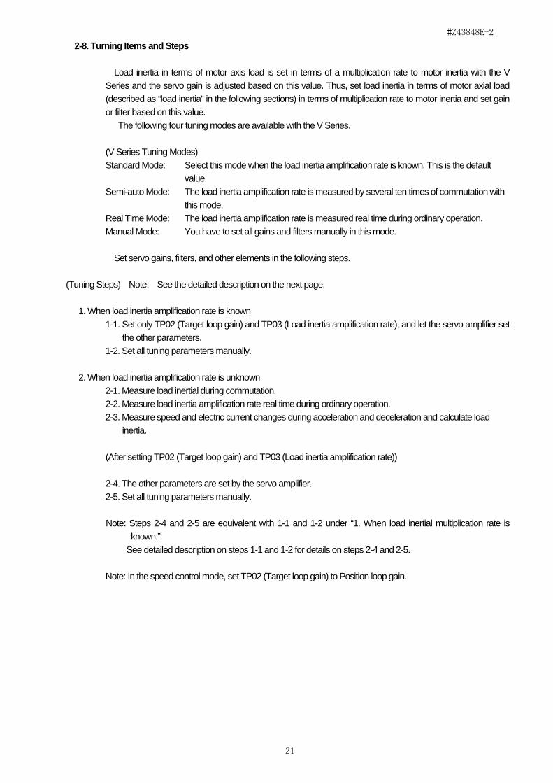
2-8-1. Tuning Mode Select Screen
Fig. 2-8-1. Tuning Mode Select Screen
Select tuning screens following the steps described in “2-8. Tuning Items and Steps” on this screen. Only selected buttons are available depending on the servo amplifier tuning mode (TP01).
Note: You can not open more than one tuning screen at the same time.
#Z43848E-2
24
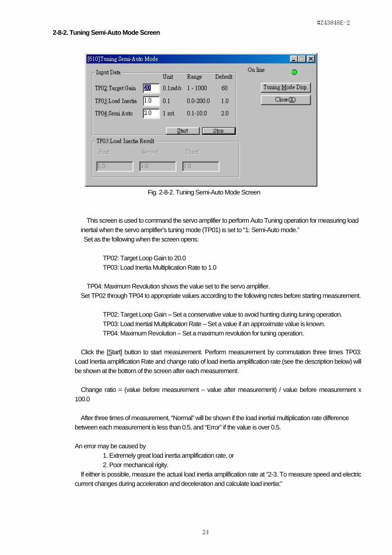
2-8-2. Tuning Semi-Auto Mode Screen
Fig. 2-8-2. Tuning Semi-Auto Mode Screen
This screen is used to command the servo amplifier to perform Auto Tuning operation for measuring load inertial when the servo amplifier’s tuning mode (TP01) is set to “1: Semi-Auto mode.”
Set as the following when the screen opens:
TP02: Target Loop Gain to 20.0 TP03: Load Inertia Multiplication Rate to 1.0
TP04: Maximum Revolution shows the value set to the servo amplifier. Set TP02 through TP04 to appropriate values according to the following notes before starting measurement.
TP02: Target Loop Gain – Set a conservative value to avoid hunting during tuning operation. TP03: Load Inertial Multiplication Rate – Set a value if an approximate value is known. TP04: Maximum Revolution – Set a maximum revolution for tuning operation.
Click the [Start] button to start measurement. Perform measurement by commutation three times TP03: Load Inertia amplification Rate and change ratio of load inertia amplification rate (see the description below) will be shown at the bottom of the screen after each measurement.
Change ratio = (value before measurement – value after measurement) / value before measurement x 100.0
After three times of measurement, “Normal” will be shown if the load inertial multiplication rate difference between each measurement is less than 0.5, and “Error” if the value is over 0.5.
An error may be caused by 1. Extremely great load inertia amplification rate, or 2. Poor mechanical rigity.
If either is possible, measure the actual load inertia amplification rate at “2-3. To measure speed and electric current changes during acceleration and deceleration and calculate load inertia:”

#Z43848E-2
25
2-8-3. Tuning Real-Time Mode Screen
Fig. 2-8-3. Tuning Real-Time Mode Screen
This screen is used to monitor TP03: Load inertial multiplication rate measured by the servo amplifier during normal operation when the servo amplifier’s tuning mode (TP01) is set to “2: Real-Time mode.”
When this screen opens, the values set to servo amplifier parameters TP02: Target Loop Gain and TP03: Load Inertia Amplification Rate are displayed.
Set values to TP02 and TP03 before starting ordinary operation.
TP02: Target Loop Gain – Set a conservative value to avoid hunting during tuning operation. TP03: Load Inertial Multiplication Rate – Set a value if an approximate value is known.
Run ordinary operation after setting values to TP02 and TP03, and if a value displayed for TP03: Load Inertia Amplification Rate gets stabilized and saturated, that means successful measurement of the load inertia amplification rate. After successful measurement of load inertia amplification rate, change TP01: Tuning Mode to “0: Standard Mode.”
If load inertial amplification rate measurement has failed and a value for TP03: Load Inertia Amplification Rate is not stabilized, the following causes are likely:
1. Extremely great load inertia multiplication rate, or
2. Poor mechanical rigidity.
If either is possible, measure the actual load inertia multiplication rate at “2-3. To measure speed and electric current changes during acceleration and deceleration and calculate load inertia:”

#Z43848E-2
26
2-8-4. Tuning Manual Mode Screen
Fig. 2-8-4. Tuning Manual Mode Screen
When the servo amplifier parameter TP01: Tuning Mode is set to “0: Standard Mode” or “3: Manual Mode,” you may measure the changes of speed and current on acceleration or deceleration during ordinary operation and calculate load inertia on this screen. Please note that that a great viscosity resistance makes servo adjustment work difficult. In such a case, calculate viscosity friction (viscosity friction bending point frequency) and adjust gain.
(Load Inertia Measurement and Calculation Steps) Open the Sampling Condition screen and measure speed and current changes during acceleration and
deceleration as illustrated above. Here, set Channel 1 to “Current (w/o Filter)” and Channel 2 to “Current (w/o Filter).
When the measurement is over, enter the following values and click “Calc1” and “Calc2” buttons to calculate load inertia. Units are specified in square brackets. (Speed and current changes during acceleration)
t1: Acceleration start time, t2: Acceleration end time [s] F1: Initial speed, F2: Ending speed [r/min] I1: Acceleration start current, I2: Acceleration end current [A]
(Speed and current changes during deceleration) t3: Deceleration start time, t4: Deceleration end time [s] F3: Initial speed, F4: Ending speed [r/min] I3: Deceleration start current, I4: Deceleration end current [A]

#Z43848E-2
27
In the Sampling Graphics screen, after measuring speed and current changes during acceleration, place
Cursor 1 and 2 on t1 and t2 respectively and click [Get Data[A]] button to acquire values t1 through I2. In the same way, on the Sampling Condition screen, after measuring speed and current changes during
acceleration, place Cursor 1 and 2 on t3 and t4 respectively and click [Get Data[B]] button to acquire values t1 through I2.
After finishing calculation of load inertia during acceleration and deceleration, click the [Average] button to obtain the average value of two above values, and calculate load inertia ratio using the “Motor Inertia” value from the “Amp Information” column on the right.
Units are specified in square brackets.
Load inertia ratio = Load inertia (obtained by calculation) / Motor inertia
After finishing the above calculation, specify the TP03: Load Inertia Ratio value on the Tuning Gain Setup screen. See “2-11. Tuning Gain Setup screen” for details on gain setting.
(Measuring Viscosity Friction Bending Point Frequency) Please note that that a great viscosity resistance makes servo adjustment work difficult. In such a case,
calculate the viscosity friction (viscosity friction bending point frequency). Measure a current value during rotation at a constant speed (F [r/min]), enter the value, and click the
[ωd = Kt * I / { F * 2π/ 60 * (Jm + Jl) }] button to obtain viscosity friction bending point frequency (wd in the figure).
When a value obtained for the viscosity friction bending point frequency is smaller than a targeted positional gain, no further work is required. Yet, if the value is greater, then adjust the value for TP05: Speed Loop Integral Gain according to the viscosity friction bending point frequency.
See “2-11. Tuning Gain Setup screen” for details on gain setting.
#Z43848E-2
28
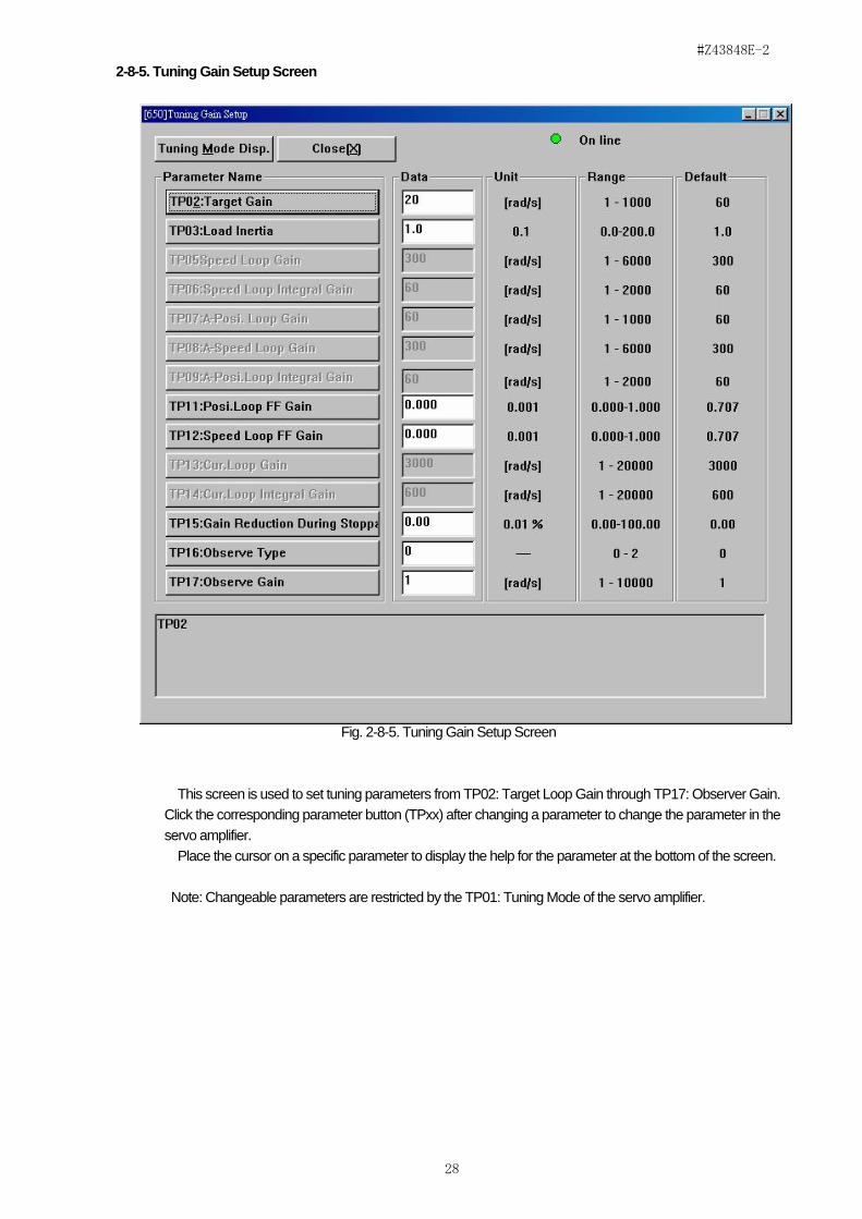
2-8-5. Tuning Gain Setup Screen
Fig. 2-8-5. Tuning Gain Setup Screen
This screen is used to set tuning parameters from TP02: Target Loop Gain through TP17: Observer Gain. Click the corresponding parameter button (TPxx) after changing a parameter to change the parameter in the servo amplifier.
Place the cursor on a specific parameter to display the help for the parameter at the bottom of the screen.
Note: Changeable parameters are restricted by the TP01: Tuning Mode of the servo amplifier.

#Z43848E-2
29
2-8-6. Tuning Filter Setup Screen
Fig. 2-8-6. Tuning Filter Setup Screen
This screen is used by an observer to set the Current Command Filter 1 and 2, Speed Feedback Filter, and Speed Command Filter parameters. Click the corresponding parameter button (TPn) after changing a parameter to change the parameter in the servo amplifier. Place the cursor on a specific parameter to display the help for the parameter at the bottom of the screen.
#Z43848E-2
30
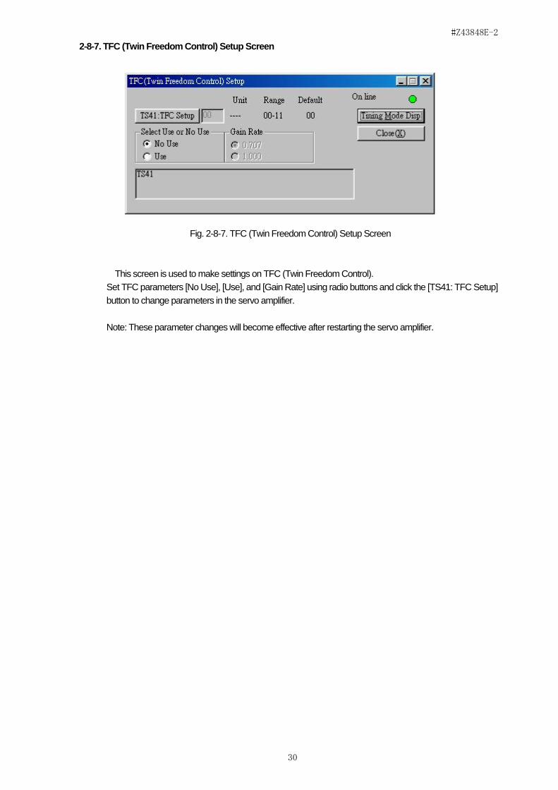
2-8-7. TFC (Twin Freedom Control) Setup Screen
Fig. 2-8-7. TFC (Twin Freedom Control) Setup Screen
This screen is used to make settings on TFC (Twin Freedom Control). Set TFC parameters [No Use], [Use], and [Gain Rate] using radio buttons and click the [TS41: TFC Setup]
button to change parameters in the servo amplifier.
Note: These parameter changes will become effective after restarting the servo amplifier.

#Z43848E-2
31
2-9. Amp Information Screen
Fig. 2-9. Amp Information Screen
This screen is used for displaying Amplifier information (Axis No.: for multi-positioner, option status, power unit status, etc.), Monitor information except those displayed on the Main Menu screen (Electronic thermal high-speed data, previous resolver ABS phase data, etc.), servo lock missing conditions, and warnings.
Check the [Validity] check box to see the values for “Resolver ABS Phase” and “ABS Sensor Rotation.” The following causes are possible as the servo lock missing conditions and warnings:
(Servo Lock Lack Condition) * IN0: PON (signal) not entered. * IN7: Operation signal [RUN] not entered. * OUT3: Servo preparation [RDY] unfinished. * Main circuit uncharged. * Dynamic break confirmation (signal) not entered. * Holding brake confirmation (signal) not entered. * Serial communication operation (signal) not entered. * Option serial communication (operation) not entered.

#Z43848E-2
32
(Warning) * Low battery charge * Origin unsaved. * Electronic thermal warning * Reverse current absorption overheat warning * Fin overheat warning
* Pulse command warning * PNLV warning

#Z43848E-2
33
2-10. Real Alarm Screen
Fig. 2-10. Real Alarm Screen
Ongoing alarms with the servo amplifier are displayed on this screen. Click alarm number [Alarm n] button to see the detective conditions and solutions for the alarm in each
column at the bottom the screen.
#Z43848E-2
34
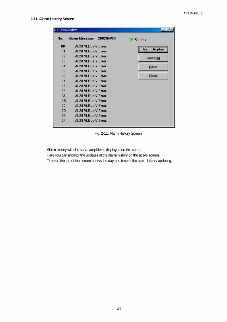
2-11. Alarm History Screen
Fig. 2-11. Alarm History Screen
Alarm history with the servo amplifier is displayed on this screen. Here you can monitor the updates of the alarm history on the active screen. Time on the top of the screen shows the day and time of the alarm history updating.

#Z43848E-2
35
2-12. Version Display Screen
2-12. Version Display Screen
The servo amplifier software version, program number, etc. are displayed on this screen.

#Z43848E-2
36
3. Additional Information
The following are descriptions on alarm detecting conditions, countermeasures, and terminology.
3-1. Alarm
Types Alarm messages Detecting conditions/countermeasures Communication error
*1 Countermeasures 1.Turn off and on the servo amplifier. 2.Turn off and on SHANS5. 3.Turn off and on your PC. 4.Check your PC’s serial port setting.
RS232C initialize error * Detective Condition The servo amplifier is not ready for communications. * Solution
RS232C cable error * Detective Condition “CTS” for the communication cable is not turned ON. * Solution: * See 1 above.
RS232C time out * Detective Condition A reply message is not received from the servo amplifier within a specified time after dispatching a command. * Solution Check that the servo amplifier is properly working.
Data dispatch error
* Detective Condition The servo amplifier detected an error with a dispatched command and returned an alarm code. * Solution: * See 1 above.
RS232C dispatched data framing error
* Detective Condition The servo amplifier detected an error with a dispatched command and returned an alarm code. * Solution: * See 1 above.
RS232C dispatched data command number error
* Detective Condition A command out of specifications was dispatched when invalid dispatch command (B) had been dispatched. * Solution: * See 1 above.
RS232C dispatched data length error
* Detective Condition The communication bytes (c) do not correspond to the dispatched command. * Solution: * See 1 above.
RS232C dispatched data check sum error
* Detective Condition The dispatched command check sum (E) does not match. * Solution: * See 1 above.
Received data error
* Detective Condition A reply data error was found.
RS232C received data status error
* Detective Condition A reply data status (B ‘) error was found. * Solution: * See 1 above.
RS232C received data length error
* Detective Condition A reply data size (C ’) error was found. * Solution: * See 1 above.
RS232C received data check sum error
* Detective Condition A reply data check sum (E ’) error was found. * Solution: * See 1 above.
RS232C received data framing error
* Detective Condition A reply data error was found. * Solution: * See 1 above.
RS232C received data parity error
* Detective Condition A reply data error was found. * Solution: * See 1 above.
RS232C received data overrun error
* Detective Condition A reply data error was found. * Solution: * See 1 above.
Received data * Detective Condition

#Z43848E-2
37
error by command
A reply data error is detected and displayed by communication command.
Command 63: Baud rate switching failure
* Detective Condition Baud rate switching failed. * Solution Check communications. Open the Environment screen and run the command again.
Command 65: Remote drive switching failure
* Detective Condition Remote drive switching failed. * Solution Check communications. Open the Remote Drive Display screen.
Command 6: Forced oscillation start failure
* Detective Condition Oscillation for “Test Oscillation,” or “Frequency Response Measurement” failed. * Solution Check communications.
Command 67: Sampling start failure
* Detective Condition Waveform sampling measurement failed. * Solution Turn off and on the servo amplifier. Restart SHAN5.
Command 69: Auto-Tuning Control – Tuning start failure
* Detective Condition Auto-tuning operation failed. 1.Servo amplifier parameter TP01: Tuning Mode is not set to “1:
Semi-Auto Mode.” 2.Servo amplifier is driven for motor test or another purpose.
* Solution 1.Rest the tuning mode parameter and restart the servo amplifier.
2. Stop the motor test if it’s conducted. Command 70: Sequence
Command failure * Detective Condition No sequence command was received for enabling “Resolver ABS Phase Counter” and “ABS Sensor Rotation” on the Amp Information screen. The motor sensor may not be set to ABS: Absolute Sensor. * Solution Check the motor sensor parameter UP02: Motor code first two digits.
Command 73: Remote Drive command Remote drive is not conducted.
* Detective Condition The sequence input command and numeric command failed during remote drive operation. The servo amplifier may not be set to the remote drive mode. * Solution Open the Remote Drive Display screen.
Command 74: Remote Drive Individual command Remote drive is not conducted.
* Detective Condition The sequence input command and numeric command failed during remote drive operation. The servo amplifier may not be set to the remote drive mode. * Solution Open the Remote Drive Display screen.
Command 78: Servo Gain Adjustment Invalid parameter number
* Detective Condition Individual parametrical changes failed on the Tuning screen. * Solution
1. Turn off and on the servo amplifier. 2. Restart SHAN5.
Operation errors, etc.
Calculation RAM error * Detective Condition Data read for monitoring data calculation failed. * Solution 1. Turn off and on the servo amplifier. 2. Restart SHAN5.
File open error * Detective Condition The specified file could not be opened. * Solution Check the file using another editor software such as Notepad.

#Z43848E-2
38
Read only file * Detective Condition You tried to write into a read-only file. * Solution Change the file property or write into another file and save it.
Waveform sampling incomplete
* Detective Condition The [Data Read] button was pressed during sampling operation. * Solution Wait until sampling completes or stop measurement, check the interval and trigger condition settings and start sampling again.
Frequency analysis invalid data setting
* Detective Condition The test oscillation time setting was too short. * Solution Set a greater value to the parameter.
Motor not locked * Detective Condition The motor was not locked when frequency analysis test oscillation and frequency response measurement started. The motor was not locked when measurement started on the Tuning Semi-Auto Mode screen. * Solution Lock the motor. See the Servo Lock Lack Condition on the Amp Information screen.
Invalid parameter name * Detective Condition An invalid parameter file name was specified. * Solution Open and modify the parameter file using another editor software such as Notepad. Receive the parameter again.
Invalid parameter number * Detective Condition The parameter number of the parameter file is not correct or duplicated. * Solution Open and modify the parameter file using another editor software such as Notepad. Receive the parameter again.
Tuning Mode error * Detective Condition The servo amplifier tuning mode is not consistent with the specifications on the SHAN5 tuning mode screens. * Solution Close the screen and modify the servo amplifier tuning mode or open a screen consistent with the specified tuning mode.
Remote Drive cannot be operated from PC
* Detective Condition This error may occur when you clicked the [PON In] and [Brake Confirm] buttons on the Remote Drive Display screen. * Solution Use external input device to use the [PON In] and [Brake Confirm] buttons.
3-2. About Help
SHAN5 has no HELP files.