Embed Size (px)
Citation preview

VIBRATIONS IN NUCLEAR APPLICATIONS
TORSIONAL VIBRATIONS IN STEAM TURBINE SHAFT TRAINSREPORT 2018:522
NUCLEAR


Torsional Vibrations in Steam Turbine Shaft Trains
HARALD BREITBACH
ISBN 978-91-7673-522-0 | © Energiforsk August 2018 | Cover photo: TVO
Energiforsk AB | Phone: 08-677 25 30 | E-mail: [email protected] | www.energiforsk.se


TORSIONAL VIBRATIONS OF SHAFT TRAINS IN STEAM TURBINES
3
Foreword
Torsional vibrations in shaft trains have become important to investigate since the electricity production in the grid is more and more done with sources wind and solar, functioning without large rotating masses. Also, the structural optimization of shaft trains has gone very far, and some combined lateral torsional vibration phenomena have been observed.
In this report a summary and a mapping of root causes, practical experiences, pos-sible means of measurement / monitoring and mitigation measures for torsional vibrations is performed.
This project has been carried out by consultant Harald Breitbach at Wölfel Engi-neering GMBH & CO. KG within the Energiforsk Vibrations research program. The stakeholders of the Vibrations program are Vattenfall, Uniper, Fortum, TVO, Skellefteå Kraft and Karlstads Energi.
These are the results and conclusions of a project, which is part of a research pro-gramme run by Energiforsk. The author/authors are responsible for the content.
TORSIONAL VIBRATIONS OF SHAFT TRAINS IN STEAM TURBINES
4
Sammanfattning
Vibrationer i kärnkraftverk kan härröra från olika källor. En av dessa är torsions-vibrationer i turbinaxeln, ett fenomen som har blivit mer intressant att studera under de senaste åren. Elproduktionen kommer i allt högre grad från energikällor som vindkraft och solceller som ger el utan stora roterande massor. Strukturopti-mering av turbinaxlar har också drivits väldigt långt, vilket ger mindre marginaler. I några fall så har torsionsvibrationer observerats.
För att minimera risken för torsionsvibrationsproblem är det viktigt att förstå vil-ken typ av problem som kan uppstå och hur det kan påverka turbinsystemet med dess olika komponenter. Förutom att förstå problemen är det självklart väldigt viktigt att veta hur man undviker problem eller mildrar effekterna av dem för att ha en säker och pålitlig drift.
Denna rapport behandlar torsionsvibrationer i turbinaxeln, beskriver möjliga grundorsaker och befintliga vibrationsdesignkriterier. En samling praktiska erfa-renheter relaterade till torsionsvibrationer i turbinaxlar ges. Den presenterar också olika typer av mätmetoder och behandlar potentiella mät- och övervakningssy-stem. Dessutom ges en översikt över åtgärder för att minska vibrationsproblemen, både i form av metoder och kommersiella system. Vidare presenteras en guide för en metodik för att detektering och lösa torsionsvibrationsproblem.

TORSIONAL VIBRATIONS OF SHAFT TRAINS IN STEAM TURBINES
5
Summary
Vibration problems in nuclear power plants can originate from different sources. One of these is torsional vibrations in shaft trains, which have become more interesting in the recent years. Electricity production in the grid is more and more performed by sources like wind and solar functioning without large rotating masses. Also, the structural optimization of shaft trains has gone very far, leading to reduced margins and some combined lateral torsional vibration phenomena have been observed.
In order to minimize the risk of torsional vibration problems, it is vital to have an understanding of what type of problems may occur and how it might affect the turbine train. Apart from understanding the problems, it is of course very im-portant to know how to avoid problems or mitigate them to have a safe and relia-ble long term operation.
This report deals with torsional vibrations in shaft trains, describing possible root causes and existing vibrational design criteria. A collection of practical experiences related to torsional vibrations in shaft trains is given. It also presents different kinds of measurement methods and deals with potential measurement & monitor-ing systems. Furthermore, an overview on mitigation measures, which are divided in procedures and commercial systems, is given. Finally, a guide for conceptually detecting and solving torsional vibration problems is provided.

TORSIONAL VIBRATIONS OF SHAFT TRAINS IN STEAM TURBINES
6
List of content
1 Introduction / Motivation 8 2 Torsional Vibrations in Shaft Trains 10
2.1 General 10 2.2 Root Causes – Non-Design Load Cases 13
RC 1.1 Subsynchronous Resonance (SSR) 13 RC 1.2 Turbine-Generator Device Dependent Subsynchronous
Oscillations (DDSO) with DC Power Converters 15 RC 1.3 Turbine-Generator Supersynchronous Torsional Interaction with
DC Power Converters 15 RC 1.4 Large AC Arc Furnaces 16 RC 1.5 Intermittent (fluctuating) Oscillations arising from Mini Steel Mill
Operation 16 RC 1.6 Variable Frequency Electric Drives 17
2.3 Root Causes – Baseline-Design Load Cases 17 RC 2.1 Transmission Line Short Circuits followed by HSR 17 RC 2.2 Planned or Emergency Line Switching Operations 18 RC 2.3 Unbalanced Phase Currents in the Grid 19 RC 2.4 Application of Power Electronics 19 RC 2.5 Equipment Connected to the Generator Terminals 20 RC 2.6 Synchronizing the Generator Out of Phase (SOP) 20 RC 2.7 Turbine-Generator Load Rejection 21 RC 2.8 Loss of Synchronism 21
2.4 Vibrational Design Criteria 21 2.5 Collection of Practical Experiences 23
2.5.1 Inquiry at Members of ENERGIFORSK 23 2.5.2 Web Research on Practical Operating Experiences 29 2.5.3 Traceable Root Causes 29
3 Measurement & Monitoring 31 3.1 Torsional Vibration measuring techniques 31
3.1.1 Direct Measurement Methods 32 3.1.2 Coder-Based Measurement Methods 34
3.2 Web search on available Monitoring Systems 36 3.2.1 Geislinger – Geislinger Monitoring 37 3.2.2 GE – SSTI (Sub-synchronous Torsional Interaction Analysis) with
Torsional Stress Relay (TSR) 37 3.2.3 TAM – Torque And More 39 3.2.4 Siemens – LMS Test. Lab Torsional vibration analysis 39 3.2.5 SUPROCK – Turbine Dynamics Monitoring System (TDMS) 40
3.3 Comparison of Commercial Systems 41 4 Mitigation Measures 43

TORSIONAL VIBRATIONS OF SHAFT TRAINS IN STEAM TURBINES
7
4.1 Mitigation Procedures 43 4.1.1 Modifications to Shift a Torsional Frequency 43 4.1.2 Delay in High Speed Reclosing HSR 44 4.1.3 Defined Step Change 44 4.1.4 Selective Transpositions of transmission lines 45 4.1.5 Harmonic Filters 45 4.1.6 Unit Interaction Factor (UIF) 45 4.1.7 Rapid Acceleration through Critical Speeds 45 4.1.8 Automatic Turbine Trip 46
4.2 Commercial mitigation systems 46 4.2.1 Torsional Vibration Damper 46
4.3 Special Mitigation Systems for Subsynchronous Resonance SSR 49 4.3.1 SSR filters in power transformer 49 4.3.2 Supplementary Excitation Damper Control (SEDC) 49 4.3.3 Static VAR compensators (SVC) 49 4.3.4 Superconducting magnetic storage units (SMES) 49
5 Problem-Solution-Matrices 51 5.1 Guide for the problem solution matrices 51
5.1.1 Monitoring & Indication Matrix 51 5.1.2 Root Cause & Investigation Matrix 52 5.1.3 Mitigation Matrix 53
6 Conclusion and Future Work 55 6.1 Conclusion 55 6.2 Future Work 55
7 List of abbreviations 56 8 List of references 57
TORSIONAL VIBRATIONS OF SHAFT TRAINS IN STEAM TURBINES
8
1 Introduction / Motivation
Nuclear power plants (NPPs) have been mainly seen as a base-load source of electricity. The main reason for this is that operating a NPP at the rated power level is usually more efficient and economical. This mode of opera-tion was possible because the need to vary the rated power arose only from safety needs (e.g. safe shutdowns in the case of load rejection) and frequency regulation required by the electric grid operator.
However that situation is changing in several countries. The share of nuclear power in the national electricity mix of some of these countries has become very important. Utilities had to implement or improve the maneuverability (load-following) capabilities of their NPPs. They have to be able to adapt the electricity supply to seasonal and daily variations of the power demand.
Another motivation for load-following with nuclear power plants comes from the large-scale deployment of intermittent electricity sources (like wind power). If there is a significant share of intermittent and nuclear power sources on the same electricity grid, NPPs must be able to operate in a load-following mode to balance the fluctuations of the total power generation, and in this case unexpected large and rapid modulations of the power de-mand could occur. [1]
Another important issue, which has to be investigated more precisely, is the effect of torsional vibrations on steam turbine-generators. The torsional load on single components like shafts or turbine blades might exceed a specified value and fail. The system can be damaged, which has harmful effects on the entire power plant. In this context the above mentioned intermittent smaller renewable electricity sources like wind and solar energy play an important role. Due to the missing stability generated by big rotating inertias like in NPPs it is obvious that there is a negative impact on the grid caused by load fluctuations. This leads to problems like subsynchronous resonances (SSR) described in Chapter 2.2.
To provide additional security to the power plant, it is first of all necessary to detect and to understand the cause of the problem / root cause. In the next step it is necessary to define instructions in case threshold values are exceed-ed. Controlling the occurring torsional vibrations with appropriate mitiga-tion measures might by necessary.

TORSIONAL VIBRATIONS OF SHAFT TRAINS IN STEAM TURBINES
9
Motivated by this background this report gives a general overview on the subject of torsional vibrations in shaft trains consisting of:
• possible root causes and operating experiences (chapter 2), • a chapter dealing with measurement & monitoring (chapter 3), • a chapter dealing with mitigation measures (chapter 4) and • problem solution matrices including flow chart (chapter 5).
TORSIONAL VIBRATIONS OF SHAFT TRAINS IN STEAM TURBINES
10
2 Torsional Vibrations in Shaft Trains
2.1 GENERAL
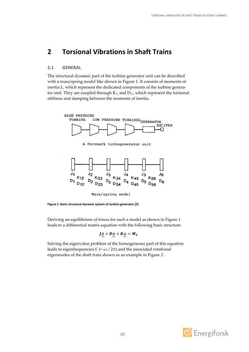
The structural dynamic part of the turbine generator unit can be described with a mass/spring model like shown in Figure 1. It consists of moments of inertia Ji, which represent the dedicated components of the turbine genera-tor unit. They are coupled through Ki,j and Di,j, which represent the torsional stiffness and damping between the moments of inertia.
Figure 1: Basic structural dynamic system of turbine generator [2]
Deriving an equilibrium of forces for such a model as shown in Figure 1 leads to a differential matrix equation with the following basic structure.
𝑱𝑱�̈�𝜑 + 𝑫𝑫�̇�𝜑 + 𝑲𝑲𝜑𝜑 = 𝑴𝑴𝑬𝑬
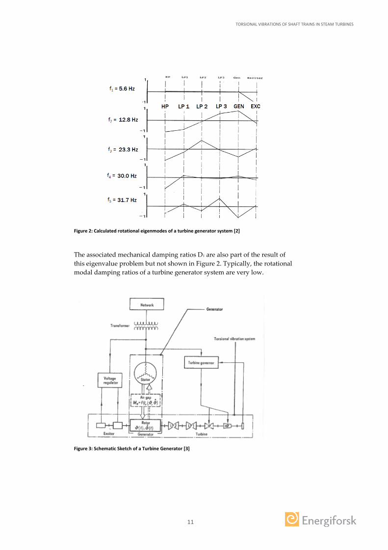
Solving the eigenvalue problem of the homogeneous part of this equation leads to eigenfrequencies fi (= ω i / 2π) and the associated rotational eigenmodes of the shaft train shown as an example in Figure 2 .
TORSIONAL VIBRATIONS OF SHAFT TRAINS IN STEAM TURBINES
11
Figure 2: Calculated rotational eigenmodes of a turbine generator system [2]
The associated mechanical damping ratios Di are also part of the result of this eigenvalue problem but not shown in Figure 2. Typically, the rotational modal damping ratios of a turbine generator system are very low.
Figure 3: Schematic Sketch of a Turbine Generator [3]

TORSIONAL VIBRATIONS OF SHAFT TRAINS IN STEAM TURBINES
12
The described mechanical system is coupled to an electrical system and therefore dynamically interacting with it. Figure 3 shows this interaction as a schematic assembly of a steam turbine generator set-up with the basic me-chanical and electric elements. The interaction between mechanical and elec-trical system and the fact that the structural damping of the torsional modes is low are the main reasons for most of the root causes leading to torsional vibration problems.
When it comes to vibration, a distinction between stator, lateral and torsional vibration must be made [3], [4]. Three different kinds of vibrations together with the basic root causes are listed in Table 1. Table 1: Distinction of different Vibrations
Stator Vibrations Shaft Lateral Vibrations Shaft Torsional Vibrations
Root
Cau
ses
Winding vibrations
Core axial vibrations
Cooling pipe vibra-tions
Unbalance - due to heat-ing (cyclic vibration)
Friction (generator)
Seawater temperature
Instability
Unequal moments of iner-tia
The grid
Equipment connected to gener-ator terminals
Operations at power plant
Interactions between grid and plant
This chapter provides background information on causes for torsional vibra-tions in shaft trains. The information is derived from literature research. In chapter 2.2 and 2.3 the most relevant disturbances that could lead to excita-tions of torsional vibrations are described in more detail. Within this de-scription also the sensitivities of the shaft train for torsional vibrations are described. In combination the disturbances and sensitivities can be inter-preted as the actual root causes of the torsional vibrations in shaft trains. These might originate from load cases, which are
• not considered in the baseline design of steam turbines (non-design load cases). They arise due to the changing philosophy in energy production with small sources and therefore they need special attention.
• already considered in the baseline design (baseline-design load cases). They don’t need special attention but are mentioned here for the sake of completeness.
The root causes (RC) are listed in Table 2 and further explained in the fol-lowing sections 2.2 and 2.3. Most of the root cause descriptions are originally taken from document [4].

TORSIONAL VIBRATIONS OF SHAFT TRAINS IN STEAM TURBINES
13
Table 2: Root Causes Summary
1. Non-Design Load Cases
RC 1.1 Subsynchronous Resonance (SSR)
RC 1.2 Turbine-Generator Device Dependent Subsynchronous Oscillations (DDSO) with DC Power Converters
RC 1.3 Turbine-Generator Supersynchronous Torsional Interaction with DC Power Converters
RC 1.4 Large AC Arc Furnaces
RC 1.5 Intermittent (fluctuating) Oscillations arising from Steel Mill Oper-ation
RC 1.6 Variable Frequency Electric Drives
2. Baseline-Design Load Cases
RC 2.1 Transmission Line Short Circuits
RC 2.2 Planned or Emergency Line Switching Operations
RC 2.3 Unbalanced Phase Currents in the Grid
RC 2.4 Application of Power Electronics
RC 2.5 Equipment Connected to the Generator Terminals
RC 2.6 Synchronizing the Generator Out of Phase (SOP)
RC 2.7 Turbine-Generator Load Rejection
RC 2.8 Loss of Synchronism
In chapter 2.4 different state of the art vibrational design criteria are de-scribed. In addition the ISO-22266 [5] as a recommendation of torsional fre-quency margins is introduced.
Chapter 2.5 summarizes the inquiry at the ENERGIFORSK members and the findings of a web research.
2.2 ROOT CAUSES – NON-DESIGN LOAD CASES
RC 1.1 Subsynchronous Resonance (SSR)
Some power companies are faced with the need to transmit large amounts of power over very long distances to main population centres. The long trans-mission lines have a very high inductive reactance, which limits the amount of power that can be transmitted in a stable manner. Adding one or more parallel transmission lines (expensive) can solve this problem or series com-

TORSIONAL VIBRATIONS OF SHAFT TRAINS IN STEAM TURBINES
14
pensating capacitors can simply be installed in the line(s). The transmission line(s) connecting a turbine-generator to a load centre are in this case not only represented by inductors and resistors but also by a capacitor.
The capacitors lower the effective reactance between the generation and the load. Their disadvantage is that they may cause problems in a turbine-generator, if they are not correctly applied. This is because now an RLC, (resistance, inductance, capacitance), circuit is established that introduces an electrical resonance frequency for the current flowing in the transmission line. The frequency of this resonant oscillating current in the transmission line is typically below the frequency of the power produced by the generator (50 Hz e.g. in Europe and Asia or 60 Hz e.g. in most parts of America) and thus named “subsynchronous resonance” or SSR.
There are two main effects caused by Subsynchronous Resonance (SSR) that might occur:
1. Torsional interaction effect
There is potential for torsional instability of shafts due to “torsional interac-tion” on machines that are connected to electrical networks. Those have ei-ther series-capacitor-compensated lines or a connection to direct current transmission lines. It is possible that they are instable due to improper oper-ation or mal-adjustment of rectifier and inverter control equipment.
The turbine-generator set is a mechanical system that typically has several resonant frequencies below 50 Hz (resp. 60 Hz). Currents that enter the gen-erator armature windings from the transmission line, electrically couple the turbine-generator rotor system and the transmission system. This arises be-cause their magnetic field interacts with the main magnetic field produced by the generator rotor. Torque pulsations are thereby produced on the gen-erator rotor at the slip (difference) frequency of these two interacting and rotating magnetic fields. These torque pulsations will cause “SSR problems” if their frequency coincides with one of the torsional natural frequencies of the turbine-generator shaft system.
Example: The line resonant frequency is 20 Hz, resulting from the addition of series capacitors. In this case potential SSR problems could arise if a tur-bine-generator on the system that generates 50 Hz current has a torsional mode at or close to thirty (50 - 20) Hz. This 30 Hz frequency is referred to as the “complement” of the line resonant frequency of 20 Hz. Under these de-scribed conditions, the shaft response torques could build up to extremely high levels.
2. Torque amplification
Very high shaft transient torques can be created by the torque amplification effect from system disturbances even if the mechanical/electrical system is

TORSIONAL VIBRATIONS OF SHAFT TRAINS IN STEAM TURBINES
15
stable. This can be because the net torsional oscillation damping caused by machine mechanical damping can become very low, if it is impacted by an electrical one, caused by the generator. This leads to a so called “undamp-ing”- effect. This phenomenon might even lead to a negative damping be-havior, i.e. an exponential amplification of the torsional oscillation, see Fig-ure 4 left side.
Figure 4: Dynamically unstable vs. stable
This phenomenon creates a potential for many damaging fatigue cycles to be experienced before the cyclic stresses decay to below the endurance limit of the shaft material. [4]
RC 1.2 Turbine-Generator Device Dependent Subsynchronous Oscilla-tions (DDSO) with DC Power Converters
DDSO is possible whenever a turbine-generator is closely interconnected with a DC power converter. This arises when turbine-generators are con-nected to HVDC transmission lines, and also when connected by AC trans-mission lines to DC power conversion equipment at industrial plants such as steel mills. In the latter case this is mainly a problem when the rating of the converter equipment is similar to that of the turbine-generators. In either case, the machine torsional system can interact with the regulating system of the DC power converters. DDSO is most likely to occur whenever the DC power converter operates in a current-regulated mode and especially in the presence of frequency dependent power controls.
RC 1.3 Turbine-Generator Supersynchronous Torsional Interaction with DC Power Converters
Turbine-generators can be exposed to high order harmonic currents entering the armature of the generator. In the case of HVDC transmission, a large power rectifier installation is required to convert the alternating currents produced by turbine generators to direct current for power transport. At the other end of the transmission line a large power inverter installation is re-

TORSIONAL VIBRATIONS OF SHAFT TRAINS IN STEAM TURBINES
16
quired to perform the opposite operation. The rectifiers and inverters can feed into the network significant current content at frequencies correspond-ing to the higher harmonics of the fundamental power system frequency. Similar interaction can occur where back-to-back DC terminals are em-ployed to electrically isolate two AC transmission systems. A back-to-back DC terminal generally consists of an AC-DC converter connected with a DC link to a DC-AC inverter.
These high order harmonic torques (sixth and above) are rarely of concern for large steam turbine-generators and no failures are known to have been associated with them.
They do however have the potential – if they are large enough – to stimulate high blade vibration on 2P and 4P turbine-generators and for retaining ring fretting at shrink fit surfaces. [4]
RC 1.4 Large AC Arc Furnaces
Steel mills may contain large AC arc furnaces of the order of 50 MW which have the potential for causing very large load fluctuations to the electrical grid.
For example, during melting of steel scrap, the load drawn by a furnace rap-idly fluctuates in a random way. This is because of electrical impedance changes as the electrodes are lowered towards the scrap and the arc/melt process initiates. The magnitude and frequency of these load swings will vary with the arc length, electrode control, the composition of the scrap, voltage tap and physical furnace characteristics.
The furnace loads combined with the action of static var (vacuum arc re-melting) controllers are a rich source of harmonics and significant imbalance to the grid. Potentially this can create high levels of negative sequence cur-rent (flow of negative sequence currents in the generators caused by unbal-anced currents in the power system) on the grid and higher harmonic cur-rents. These could produce excessive generator rotor heating and high gen-erator torsional excitations at 2xN and higher. [4]
RC 1.5 Intermittent (fluctuating) Oscillations arising from Mini Steel Mill Operation
The production of steel has changed from large integrated mills to smaller, steel mini mills. Mini mills use electric arc furnaces to melt steel. The arc furnaces show unusual loads that generate harmonics and cause real and reactive power fluctuations and sudden power changes accompanied by unbalanced operation.
The reactive power swings can interact with the torsional dynamics of near-by turbine-generators. If these disturbances are propagating throughout the
TORSIONAL VIBRATIONS OF SHAFT TRAINS IN STEAM TURBINES
17
utility system, they can affect power plant controls, protection, metering and even interact with distant turbine-generators. [4]
RC 1.6 Variable Frequency Electric Drives
Variable or adjustable frequency electric drives are becoming increasingly common for large compressor, pump and blower applications. Such equip-ment may be used in large steam turbine generator power plants and at neighboring industrial plants.
For these applications the potential for mechanical damage to the machine shafts and other systems is high unless precautions are taken. This is be-cause of the frequent run-ups and run-downs in rotational speeds of ma-chines driven by electric motors. Also the large number of potential operat-ing speeds and hold points cause a significant risk of resonant torsional re-sponses. At low rotational speeds the frequency of the harmonic torques will also be low. They could coincide with some of the lower order and respon-sive torsional modes of the coupled machine. [4]
2.3 ROOT CAUSES – BASELINE-DESIGN LOAD CASES
RC 2.1 Transmission Line Short Circuits followed by HSR
As the generator is electrically connected to the grid by a step-up transform-er, short circuits or faults will directly affect the turbine-generator. Most naturally induced faults (short circuits) occur as a result of lightning surge and subsequent dielectric breakdown between one phase and ground. These are usually temporary ones that are cleared by tripping and reclosing line circuit breakers. This process is also called “High Speed Reclosing” (HSR).
The low damping of turbine-generator torsional modes lead to extremely high transient torques in the machine shafts when they respond to a HSR process. The top trace in Figure 5 shows the fault torque waveform that is applied to the generator rotor. The bottom trace shows the resulting torsion-al response in one shaft. The peak shaft response almost doubles, following opening the circuit breaker (fault clearance) and then again following the combined result of unsuccessful reclosure and final fault removal. [4]

TORSIONAL VIBRATIONS OF SHAFT TRAINS IN STEAM TURBINES
18
Figure 5: Torsional Response Reinforcement [4]
RC 2.2 Planned or Emergency Line Switching Operations
Transmission lines are taken out of service, and put back into service, for many reasons. The turbine-generators on the system cannot change phase angle or speed instantaneously. This results in a step change in the generator output power and a corresponding mechanical shock to the machine.
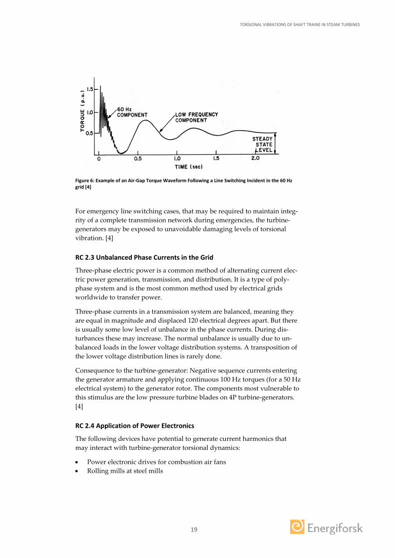
Figure 6 shows an example of the calculated generator electromagnetic torque applied to the generator (the air-gap torque) caused by a transmis-sion line switching incident. The step change in torque at time zero of about 0.5 per unit slowly decays in magnitude. It starts at a frequency produced by the average power output of the turbine-generator relative to the power system. It is about 1.5 Hz power swing frequency in this example. Superim-posed on this low frequency power torque is a rapidly decaying 60 Hz torque component. It is produced by the DC-offset currents flowing in the stator winding of the generator. The flux produced by these offset currents interacts with the main rotor flux to produce the oscillating torque at the slip frequency of 60 Hz.
TORSIONAL VIBRATIONS OF SHAFT TRAINS IN STEAM TURBINES
19
Figure 6: Example of an Air-Gap Torque Waveform Following a Line Switching Incident in the 60 Hz grid [4]
For emergency line switching cases, that may be required to maintain integ-rity of a complete transmission network during emergencies, the turbine-generators may be exposed to unavoidable damaging levels of torsional vibration. [4]
RC 2.3 Unbalanced Phase Currents in the Grid
Three-phase electric power is a common method of alternating current elec-tric power generation, transmission, and distribution. It is a type of poly-phase system and is the most common method used by electrical grids worldwide to transfer power.
Three-phase currents in a transmission system are balanced, meaning they are equal in magnitude and displaced 120 electrical degrees apart. But there is usually some low level of unbalance in the phase currents. During dis-turbances these may increase. The normal unbalance is usually due to un-balanced loads in the lower voltage distribution systems. A transposition of the lower voltage distribution lines is rarely done.
Consequence to the turbine-generator: Negative sequence currents entering the generator armature and applying continuous 100 Hz torques (for a 50 Hz electrical system) to the generator rotor. The components most vulnerable to this stimulus are the low pressure turbine blades on 4P turbine-generators. [4]
RC 2.4 Application of Power Electronics
The following devices have potential to generate current harmonics that may interact with turbine-generator torsional dynamics:
• Power electronic drives for combustion air fans • Rolling mills at steel mills
TORSIONAL VIBRATIONS OF SHAFT TRAINS IN STEAM TURBINES
20
• DC arc furnaces • High voltage DC (HVDC) converters
However the rating of the power converters needs to be significant com-pared to that of the turbine-generators in order to cause large enough tor-sional oscillations to be of concern. [4]
RC 2.5 Equipment Connected to the Generator Terminals
The most severe torsional incidents on the turbine-generator are from those faults that occur on equipment connected to the generator terminals or be-tween the high voltage terminals of the generator step-up transformer and the unit circuit breaker(s).
These faults are severe due to the electrical proximity to the generator and because the fault current will be sustained or even continue to grow until the magnetic flux of the generator decays to a low value. This is because of the inability of the generator during the fault to export real power to the system.
This results in over-speeding of the turbine-generator shaft because the power is converted to increased rotational speed of the machine. Manufac-turers often establish design limits for these incidents in terms of limiting the amount of yielding in the shaft nominal cross sections. The harmonics that are generated by the power electronics equipment – if present and not fil-tered out – might interact with the turbine-generators. [4]
RC 2.6 Synchronizing the Generator Out of Phase (SOP)
Synchronizing a turbine-generator to the transmission network during the start-up sequence results in a torsional disturbance to the machine unless it is done perfectly. Mal-synchronization produces mainly an impulsive step change and a 50 Hz (resp. 60 Hz) torque component in the generator air-gap torque.
Appropriate equipment is commonly used to automatically synchronize a generator by matching the phase angle difference between the generator and system voltage to minimize the disturbance. A phase angle of 10 degrees or less generally results in vibration responses that can be sustained by the machine an indefinitely large number of times. Synchronizing in this win-dow is practical.
Mistakes however occur, which result in synchronization at close to the worst possible angle. This happens when the manual operation is been per-formed wrongly or when the automatic equipment is wrongly operating or improperly connected. This results in a severe transient disturbance in the turbine-generator.

TORSIONAL VIBRATIONS OF SHAFT TRAINS IN STEAM TURBINES
21
A loss of fatigue life in the turbine-generator shafts with rotor-realignment and rebalancing including replacement of coupling hardware and possibly more extensive rotor shafting repairs are necessary. [4]
RC 2.7 Turbine-Generator Load Rejection
Sometimes a turbine-generator becomes isolated from the power system while it is loaded. This causes a mechanical shock to the unit. If the turbine and excitation control system is in the automatic operating mode, it should control the speed and voltage of the unit to prevent damage.
From a torsional vibration standpoint, just prior to the load rejection, the shaft system will be twisted up under the influence of the turbine rotor steady-state torques and the generator load torque. When these torques are instantaneously released due to the load rejection, the shaft system will oscillate back and forth primarily at the frequency of the first flexible torsion mode of the turbine-generator. These mechanical oscillations will then slowly decay.
Even when a load rejection occurs at full load the torsional duty on the tur-bine-generator shafts is usually moderate and should be able to be sustained many times without significant loss of fatigue life. The fatigue duty is prob-ably the most severe on the blades in the LP turbines of 4P units. [4]
RC 2.8 Loss of Synchronism
A turbine-generator unit might lose synchronism with other generators on the power system. In this case the unit will increase speed because the aver-age electrical power output of the generator is less than the power output of the turbines. The electromagnetic coupling or lock is lost between the gener-ator and the rest of the power system. Under this situation the magnetic poles of the generator rotor and stator are rotating at different speeds.
This condition is referred to as pole slipping. With each pole slippage, the generator rotor and stator experience a torque pulsation. This may cause mechanical duty to turbine-generator rotating parts and to the generator stator system.
If pole slipping was sustained and the pulsation frequency (slip frequency) was to approach or equal one of the torsional natural frequencies of the ma-chine, the magnitude of the pulsations could be amplified to levels that are damaging components. If, however, the unit is isolated from the power sys-tem quickly, serious damage to the unit is unlikely. [4]
2.4 VIBRATIONAL DESIGN CRITERIA
Torsional vibration will occur when an applied constant torque changes to a transient behavior, or when oscillating torques are applied to the turbine-

TORSIONAL VIBRATIONS OF SHAFT TRAINS IN STEAM TURBINES
22
generator. Chapters 2.2 and 2.3 discuss the root causes of such typical tor-ques, to which an operating turbine-generator may be subjected.
To prevent e.g. a turbine-generator from serious damage due to torsional vibration, standardized design criteria are available. Such a standard is ISO-22266 [5]. This standard is written to cover any unit in the world. It should be noted that all of the specific torsional frequency margin values herein are listed as “Informative”. They are for guidance. The ISO standard suggests a ±1 Hz margin to the dedicated 1xN / 2xN frequency (B in Figure 7). ISO spe-cifically addresses unstable grid frequencies by allowing a deviation of up to a ±2.5% (as shown in Figure 7). The ISO standard is written generally to al-low for both stable and non-stable grid frequencies. If a unit is in a stable grid, a smaller value than value A (allowable grid frequency variation) can be assumed.
Figure 7 is a summary of the ISO torsional frequency exclusion zones. It has to be noted that the exclusion zones get smaller if better test data is available. In a stable grid, ISO suggests a ±3.5% (B+C) frequency margin by analysis only. When the ISO standard applies to a unit with an unstable grid fre-quency, the resulting frequency margin can extend up to ±6.0% (A+B+C).
Figure 7: ISO-22266 Torsional frequency margin [5]
The “frequency margin” is the difference between a natural frequency of the shaft system and the potential excitation frequency, which could be caused by any of the known root causes. The frequencies that powertrains must avoid are especially the line frequency (1xN) and twice the line frequency (2xN). (1xN: 50 Hz or 60 Hz, 2xN: 100 Hz and 120 Hz).

TORSIONAL VIBRATIONS OF SHAFT TRAINS IN STEAM TURBINES
23
Remark: It shall be noted at this point already that many of all experienced fail-ures can be traced back to a 2xN excitation exciting a resonance mode, which contained a shaft vibration mode (see chapter 2.5.3 Traceable Root Causes).
Having adequate frequency margin is critical for safe operation of power-trains. The International Standards Organization (ISO) has recommenda-tions for torsional frequency margin. According to Fortum and Forsmark (members of Energiforsk) the frequency margin can even extend up to ±10%. It is a normal criteria when new equipment is bought [6].
2.5 COLLECTION OF PRACTICAL EXPERIENCES
This subchapter deals with practical experiences made by members of ENRGIFORSK (chapter 2.5.1) and by operators found by web research (chapter 2.5.2).
The practical experiences in the context of this chapter are failures that po-tentially lead to an outage of the turbine. Generally there are at least 3 differ-ent kinds of failures:
1. Fracture, 2. gross structural damage and/or 3. cracking of components
Each failed component can be traced back to a certain failure, which is caused by a certain failure mechanism, which again can be traced back to a certain root cause.
2.5.1 Inquiry at Members of ENERGIFORSK
In order to collect practical experience first of all the members of ENER-GIFORSK were asked to fill in a questionnaire, asking for relevant infor-mation to their power plant and the practical experiences they made with respect to failures or potential failures. Four members submitted data from their power plant:
1. Oskarshamn 3 2. Forsmark 1 and 2 and 3 3. Ringhals 1, 2, 3, 4 4. Olkiluoto
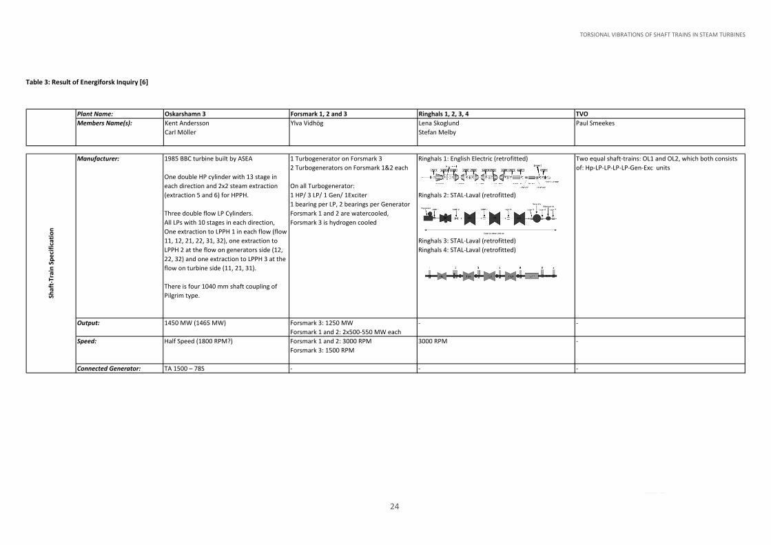
The result of the inquiry is summarized in Table 3. Amongst the members who participated to this inquiry only “Forsmark” reports a vibration prob-lem including failures (cracks in blade). Suspected root cause is SSR excited torsional vibrations in resonance of the attached fan blades.
It has to be noted that all information given in Table 3 is with respect to tor-sional vibrations.
TORSIONAL VIBRATIONS OF SHAFT TRAINS IN STEAM TURBINES
24
Table 3: Result of Energiforsk Inquiry [6]
Plant Name: Oskarshamn 3 Forsmark 1, 2 and 3 Ringhals 1, 2, 3, 4 TVOMembers Name(s): Kent Andersson
Carl MöllerYlva Vidhög Lena Skoglund
Stefan MelbyPaul Smeekes
Manufacturer: 1985 BBC turbine built by ASEA
One double HP cylinder with 13 stage in each direction and 2x2 steam extraction (extraction 5 and 6) for HPPH.
Three double flow LP Cylinders.All LPs with 10 stages in each direction, One extraction to LPPH 1 in each flow (flow 11, 12, 21, 22, 31, 32), one extraction to LPPH 2 at the flow on generators side (12, 22, 32) and one extraction to LPPH 3 at the flow on turbine side (11, 21, 31).
There is four 1040 mm shaft coupling of Pilgrim type.
1 Turbogenerator on Forsmark 32 Turbogenerators on Forsmark 1&2 each
On all Turbogenerator:1 HP/ 3 LP/ 1 Gen/ 1Exciter1 bearing per LP, 2 bearings per GeneratorForsmark 1 and 2 are watercooled, Forsmark 3 is hydrogen cooled
Ringhals 1: English Electric (retrofitted)
Ringhals 2: STAL-Laval (retrofitted)
Ringhals 3: STAL-Laval (retrofitted)Ringhals 4: STAL-Laval (retrofitted)
Two equal shaft-trains: OL1 and OL2, which both consists of: Hp-LP-LP-LP-LP-Gen-Exc units
Output: 1450 MW (1465 MW) Forsmark 3: 1250 MWForsmark 1 and 2: 2x500-550 MW each
- -
Speed: Half Speed (1800 RPM?) Forsmark 1 and 2: 3000 RPMForsmark 3: 1500 RPM
3000 RPM -
Connected Generator: TA 1500 – 78S - - -
Shaf
t-Tr
ain
Spec
ifica
tion

TORSIONAL VIBRATIONS OF SHAFT TRAINS IN STEAM TURBINES
25
Plant Name: Oskarshamn 3 Forsmark 1, 2 and 3 Ringhals 1, 2, 3, 4 TVOMembers Name(s): Kent Andersson
Carl MöllerYlva Vidhög Lena Skoglund
Stefan MelbyPaul Smeekes
Eigenfrequencies [Hz] up to 200 Hz:
In Report (needs NDA) 6.812.517.188.6… (see Attachments)
Ringhals 1: 10.2 18.6 23.8 57.5 (HP-mode)62.5 (Generator, exciter mode)128.9 (Generator, exciter mode)150.0 (Generator, exciter mode)190.6
Ringhals 2:12.523.031.032.9197.7
7.459.1318.2523.1327.7535.38
Associated Modeshapes: In Report (needs NDA) Calculated Modes Forsmark 3 (from attachment)
Ringhals2: -
Dyna
mic
Beh
avio
r of S
haft
-Tra
in

TORSIONAL VIBRATIONS OF SHAFT TRAINS IN STEAM TURBINES
26
Plant Name: Oskarshamn 3 Forsmark 1, 2 and 3 Ringhals 1, 2, 3, 4 TVOMembers Name(s): Kent Andersson
Carl MöllerYlva Vidhög Lena Skoglund
Stefan MelbyPaul Smeekes
Manufacturer: ? Westinghouse – Analogy machines - LMS, presently Siemens on OL2
Date of Installation: ? 1985 - Summer 2012
Sensortype: Relative shaft vibrations 0-peak, Velocity transducers on bearings
- - Optical ( OptelThevonMulti YO), zebra- painting
Number of Sensors: 21 Vel. sensors on bearings, 22 shaft sensors
- - 5
Sensorlocations: Bearings (pedestal) and shaft (Gland boxes) - -
Signal Analysis: Yes … - - LMS TestLab
Alarm & Trip Values: Yes … - - No
Experiences with System: ? - - Works poorly
Advantages / Shortcomings of Monitoring Systems:
? +: Forsmark 3: Measured Frequencies correct but not the amplitudes
(However after several changes of rotors – new LPs, new HP, new generator in steps during 30 years – it has not been able to modify the system to be correct for the new rotor)
-: Loss of life calculation not possible because amplitudes unknown
- Measurement system only for temporary measurements, not long term monitoring.
Zepra-painting and optical sensors are not a good choice for long term use.
Zepra-tapes pulled away directly when RPM increased up to 3000.
Zepra-painting works a little bit better, but is very sensitive to dirt and surface damages.
Optical sensors and cables work poorly in cases like this.
Mon
itorin
g Sy
stem

TORSIONAL VIBRATIONS OF SHAFT TRAINS IN STEAM TURBINES
27
Plant Name: Oskarshamn 3 Forsmark 1, 2 and 3 Ringhals 1, 2, 3, 4 TVOMembers Name(s): Kent Andersson
Carl MöllerYlva Vidhög Lena Skoglund
Stefan MelbyPaul Smeekes
Is the grid prone to exciting torsional vibrations (SSR):
Not in the past. However, there is a new DC cable to/from Balticum installed which can occur SSR in the future.
Yes, power stations are sensitive due to the position in the power net
- No
- -Torsional vibration problem detected or experienced:
- SSR excitation, last stage blade resonance made cracks in the root of 2 blades mounted 180 degrees apart.
- -
Date: - 1995 - -
Suspected Rootcauses: - SSR excited blade resonance in last stage on one LP
- -
Means of Detection: - Inspection and analysis, investigation - -
Initiated Consequences / Mitigation:
- Cracks in last stage blade – Risk of falling off. Stopped in time.
New design of turbine and turbine blades mounted, new calculations to avoid problem. The SSR (monitoring)system can trip the unit and have been upgraded when changing the machine.
Clear demands/criteria for torsional natural frequencies to avoid once and twice the grid frequency (50 Hz and 100 Hz) and the running speed (25 Hz). Not allowed in the range +/- 10 % around those frequencies. Shown with calculations and verified with measurements during operation after.
- -
Effects causing Torsional Vibrations expected from the Grid in the Future:
- - - In future, the low inertia of grid could cause problems.
Increasing DC power transmission between countries could cause problems
Grid

TORSIONAL VIBRATIONS OF SHAFT TRAINS IN STEAM TURBINES
28
Plant Name: Oskarshamn 3 Forsmark 1, 2 and 3 Ringhals 1, 2, 3, 4 TVOMembers Name(s): Kent Andersson
Carl MöllerYlva Vidhög Lena Skoglund
Stefan MelbyPaul Smeekes
Countermeasure on shaft or grid side:
- Forsmark 3 has a SSR system, which disconnects the station from the power net in case of too high vibration on the power net.
Remark: Although not measuring the actual torsional vibrations levels (only the torsional frequencies to verify) they were ok to compare with calculations and avoid coincidence with the blade resonances.
- Some sort of electrical damper that damps out a specific narrow frequency band.
Disadvantage is that the amplitudes around the damped frequencies are amplified.
Triggered Event(s): - SSR disturbances quite often since the unit started – partly minimized in the power net.
- Just a precaution to stay out of trouble.
Cause of Event(s): - - - -
Miti
gatio
n

TORSIONAL VIBRATIONS OF SHAFT TRAINS IN STEAM TURBINES
29
2.5.2 Web Research on Practical Operating Experiences
This subchapter assembles turbine-generator failures that have been determined to be torsionally induced.
Examples of Involved Failures
Table 4 shows failure experiences in terms of machine definition, identification of failed component(s), failure mechanism and clarifying comments. The main source for the introduced failures is [4].
Table 4: Involved Failures [4]
Date, Unit, Operator Failed Components Failure Mech-nism
Comments
1971, Mohave Unit 2 (2P), Southern California Edison
Generator collector shaft. Hole Burnt into shaft from electrical grounds arcing
Collector ring insulation failure due to heat generation in shaft from strain oscillations.
Two separate shaft failure incidents due to SSR. Second failure occurred because root cause was not properly identified after first failure.
1974, Prairie Island Unit 1 (4P), Nuclear Management Co./NSP
Blade failures High cycle fatigue (HCF)
Torsional resonance near 120 Hz. L-1 blades and L-2 disc were modified.
1985, Maanshan (4P), Taiwan Power
8 last stage blades, alternator shaft
High cycle fatigue (HCF)
Torsional resonance near 120 Hz during off frequency operation. The alternator shaft fracture was a conse-quence of the blade fractures.
1985, Montecello Unit 1 (4P), Nuclear Management Co./NSP
None – but there was consumption of shaft fatigue life.
High shaft torsional oscilla-tions
Loss of shaft fatigue life due to a 700 MW oscillation at a HVDC inverter substation. Unit required rebalancing.
1987, Comanche Unit 2 (2P), XCEL
Cracked generator shaft at main shrunk on coupling keyway
Fretting Fatigue Torsional frequency close to 120 Hz. Steel mill in vicinity was source of excitation. Shaft was repaired and a new coupling installed.
1993, Susquehanna Unit 1 (4P), PPL
Two L-1 stage blade failures in LPC turbine
High cycle fatigue (HCF)
Torsional resonance near 120 Hz. An inertia ring was installed to detune the torsional mode.
1994, Comanche Unit 2 (2P), XCEL
Body mounted retaining ring fracture
Torsional high cycle fretting fatigue
Power oscillations from local steel mill that corresponded in frequency with supersyn-chronous T/G torsional mode at 114.5 Hz.
1998, Port Washington Unit 1 (4P), Wisconsin Electric Power
Spindle mounted retaining ring cracks
Torsional high cycle fretting fatigue
Postulated that electrical interaction with steel mill stimulated subsynchronous mode.
2002, South Texas Project Unit 2 (4P), South Texas Project Nuclear Operating Co.
One LP blade fracture
High cycle fatigue (HCF)
Many cracked blades. Machine torsional resonance near 120 Hz was subsequently detuned. Unit 1 has also experienced LP blade fatigue cracking.
2004, Dresden Units 2 & 3 (4P), Exelon
Cracked generator shafts at main shrunk on coupling keyway
Cracks initiated by fretting. Cracks grew by HCF.
Intermittent oscillating torques postulated to be root cause. Shaft keyway was redesigned. Torsional monitors put into service.
2.5.3 Traceable Root Causes
The experienced failures in Table 4 and the one failure reported by Forsmark [6] are traceable to root causes. Below they are summarized to groups and assigned to a certain root cause. Apparently, the failures can all be traced back to the ones de-scribed in 2.2 and 2.3.

TORSIONAL VIBRATIONS OF SHAFT TRAINS IN STEAM TURBINES
30
• Failure of low pressure turbine blades on several 4P units. The crack-ing/fracture incidents arose from torsional resonance near 120 Hz probably caused by RC 2.3 and 2.7 (see chapter 2.3)
• Shaft failures on 2P and 4P units. Two failures arose from SSR (see RC 1.1 in chapter 2.2) and in another case a shaft fractured as a result of the unbalance effects of multiple turbine blade fractures. Three shaft cracking incidents have been experienced from 120 Hz torsional excitations probably caused by RC 2.3 (see chapter 2.3).
• Retaining ring failures on one 4P and one 2P unit. The first failure was ring cracking due to DDSO (see RC 1.2 in chapter 2.2). It was due to involvement of DC equipment at a steel mill. The second was a ring fracture due to supersyn-chronous torsional interaction from power frequency spikes at a steel mill (see RC 1.3 under chapter 2.2).

TORSIONAL VIBRATIONS OF SHAFT TRAINS IN STEAM TURBINES
31
3 Measurement & Monitoring
There are different ways to detect torsional vibration problems. Table 5 shows gen-eral ways of detection grouped in 2 different methods / approaches and subdivid-ed in different indications.
Table 5: Ways to detect torsional vibration problems
Method / Approach Indication
Online monitoring during operation Torsional Amplitudes
Torque values / torsional stress
Grid frequency variations
Offline Inspection Cracks by fretting
Cracks by HCF (high cycle fatigue)
It should be mentioned that it is possible to detect impacts on the structure during standstill periods by offline inspection. Nevertheless this chapter is focused on the online monitoring during operation.
3.1 TORSIONAL VIBRATION MEASURING TECHNIQUES
A typical turbine-generator has instrumentation for continuous, long term moni-toring of lateral (bending) vibration so that indications of changes can be observed and actions taken before any significant damage due to lateral vibration occurs. This includes shutting down the turbine-generator quickly to avoid extensive damage if a serious problem arises. However, the standard vibration instrumenta-tion only measures lateral vibration of the turbine-generator, it reacts to changes in balance or alignment of the machine or for other reasons.
Torsional vibration, however, occur randomly and intermittently due to sudden changes in the applied torques and is generally an indication of stimulus from outside the shaft train (see chapter 2.2).
The lateral vibration instrumentation is incapable of measuring the torsional re-sponse of the turbine-generator. Consequently, significant torsional vibration can occur at a turbine-generator without any warning from the lateral vibration in-strumentation prior to a significant failure.
Torsional vibration monitoring during operation shall measure and observe tor-sional vibration and provide a warning that the turbine-generator is being subject-ed to an unexpected torsional excitation or that it is operating close to torsional mode resonances caused by a harmonic torque. In the last mentioned case the ISO 22266-1 [5] provides recommendations for allowable frequency variations in opera-tion (see Figure 7).

TORSIONAL VIBRATIONS OF SHAFT TRAINS IN STEAM TURBINES
32
Various measuring techniques are available to detect torsional vibrations. The best sensor can be selected for each individual case based on the physical quantity to be measured, the type of analysis, the accessibility of the shaft, the ease of instrumen-tation and the required accuracy. [7]
Two different measurement methods with various types of sensors are used for torsional vibration measurements. These are described in this chapter.
Remark: All of the listed measurement techniques are suitable for torsional vibra-tions measurements on large turbo generators. But a critical assessment of all known advantages and disadvantages is mandatory.
3.1.1 Direct Measurement Methods
Direct measurement methods are conducted with sensors, which are directly mounted on the shaft or applied with laser interferometers.
Linear Accelerometer
Table 6: Linear Accelerometer
Function / Mounting + -
Two linear accelerometers are fixed in parallel on the rotating shaft as shown below. The two accelerometers can measure the tangential ac-celerations atan. They move in the opposite di-rection in the fixed system of the rotation axis. Any translational acceleration of the shaft is cancelled by taking the average of both accel-erometers: atan(t) = [a1(t) + a2(t)] / 2
High dy-namic range
Expensive te-lemetry or sensi-tive slip rings needed
Low sensi-tivity to translational vibrations
Mass loading for relatively small shafts (e.g. shaft unbalance)
Centrifugal forc-es may lead to dangerous loss of sensors
No absolute angular position available

TORSIONAL VIBRATIONS OF SHAFT TRAINS IN STEAM TURBINES
33
Angular Accelerometer
Table 7: Angular Accelerometer
Function / Mounting + -
E.g. fully integrated linear accelerometer
Similar to linear accel-erometer
Similar to linear accelerometer
Strain Gauges
Table 8: Strain Gauges
Function / Mounting + -
Measuring torsional elongation or stress (shear stress) strain gauges glued on the shaft
Direct meas-urement of torsional elongation or shear stress
Expensive te-lemetry or sensitive slip rings needed
Low sensitivi-ty to other deformation than torsional
Mass loading for relatively small shafts (e.g. shaft un-balance)
Centrifugal forces may lead to dangerous loss of sensors
Exact angular speed and position not known, no absolute posi-tion available by only using strain gauges

TORSIONAL VIBRATIONS OF SHAFT TRAINS IN STEAM TURBINES
34
Dual-Beam Laser Interferometer
Table 9: Dual-Beam Laser Interferometer
Function / Mounting + -
Angular velocity is computed from veloci-ty measured in direction of the laser beams on the two pointed areas through the Doppler shift.
Contactless
Expensive device
Low sensitivity to translational vibra-tions
Exact angular speed and posi-tion not known, no absolute position availa-ble
Low sensitivity to shape of the shaft
No usage in confined envi-ronment
Easy instrumenta-tion
Visual contact between shaft and sensor re-quired.
3.1.2 Coder-Based Measurement Methods
Coder-based techniques make use of equidistantly-spaced markers on the shaft or rotating part. The sensor measures every time a marker passes in front of a sensor and the time difference between two markers is used to estimate the angular veloc-ity.
The coder-based techniques have the advantage of delivering RPM and discrete angle position. The data resolution is determined by a number of markers: the more markers, the more accurate information, although for low speeds, more markers than for high speeds are needed. Different types of setups are used to provide markers (coder); for example, stripes drawn on the shaft. Also, different sensors are available to detect the markers, such as electro-magnetic pickup or optical sensors. Incremental encoders are devices combining the coder and the sensor in a single hardware. Magnetic pickups, opti-cal sensors and incremental encoders all output periodic signals to be processed into angular velocity and/or position by acquisition hardware. The torsional-vibration measurement system must accurately detect the time stamps at which a predefined level is crossed by the periodic-sensor signal assuming a fixed angle increment between pulses. [7]
TORSIONAL VIBRATIONS OF SHAFT TRAINS IN STEAM TURBINES
35
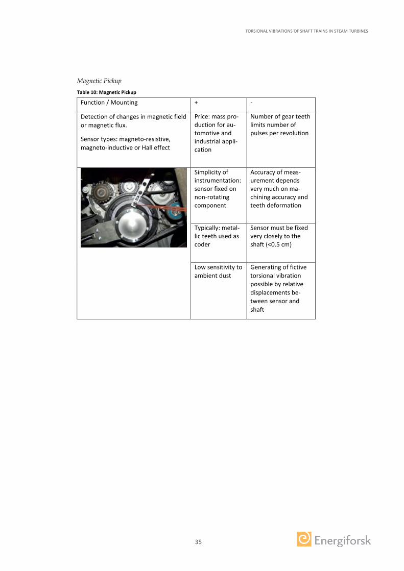
Magnetic Pickup
Table 10: Magnetic Pickup
Function / Mounting + -
Detection of changes in magnetic field or magnetic flux.
Sensor types: magneto-resistive, magneto-inductive or Hall effect
Price: mass pro-duction for au-tomotive and industrial appli-cation
Number of gear teeth limits number of pulses per revolution
Simplicity of instrumentation: sensor fixed on non-rotating component
Accuracy of meas-urement depends very much on ma-chining accuracy and teeth deformation
Typically: metal-lic teeth used as coder
Sensor must be fixed very closely to the shaft (<0.5 cm)
Low sensitivity to ambient dust
Generating of fictive torsional vibration possible by relative displacements be-tween sensor and shaft

TORSIONAL VIBRATIONS OF SHAFT TRAINS IN STEAM TURBINES
36
Optical sensor
Table 11: Optical Sensor
Function / Mounting + -
Generating of electrical signal de-pending on light intensity.
Coders with sufficient visible con-trast mounted on the shaft or its end (e.g. zebra tapes or zebra discs)
Simplicity of instrumen-tation: sensor fixed on non-rotating component
High sensitivity to ambient light
Direct mounting on gears possible
Visual contact between shaft and sensor re-quired.
Coder easy to implement by using contrasted paint or zebra tapes
Measurement of very high pulse rate
Incremental Encoder
Table 12: Incremental Encoder
Function / Mounting + -
Combination of coder and sensor in one device (often optical technology)
Three embedded coders
High-pulse rate (typically 50 to 500)
Relatively complex instrumentation limits usage for in-vehicles or mobile measurement
Duty-cycle related analy-sis
3.2 WEB SEARCH ON AVAILABLE MONITORING SYSTEMS
In this chapter existing measurement systems for online monitoring are listed, based on a web search and direct communication with the suppliers.
TORSIONAL VIBRATIONS OF SHAFT TRAINS IN STEAM TURBINES
37
For each system a short description of the dedicated instrumentation, hardware and software (i.e. analysis) that is used, are given.
3.2.1 Geislinger – Geislinger Monitoring
Description:
“Reliable sensors in combination with sturdy measuring gears detect torsional vibrations precisely in couplings, dampers, camshafts and drive shafts. Custom-ized algorithms filter and calculate static and dynamic twists between the elements as well as the vibratory angle. The calculated torsional vibration values are shown on the color display as figures, bar graphs or as FFT analyzed values. If the operat-ing limit is exceeded, an alarm is activated.
The system features internal data recording from this valuable information, Geis-linger specialists can evaluate if the damper or coupling is functioning correctly. The statement issued can be used as an official service document. It is recognized by classification societies and can also prevent carrying out an overhaul.” [8]
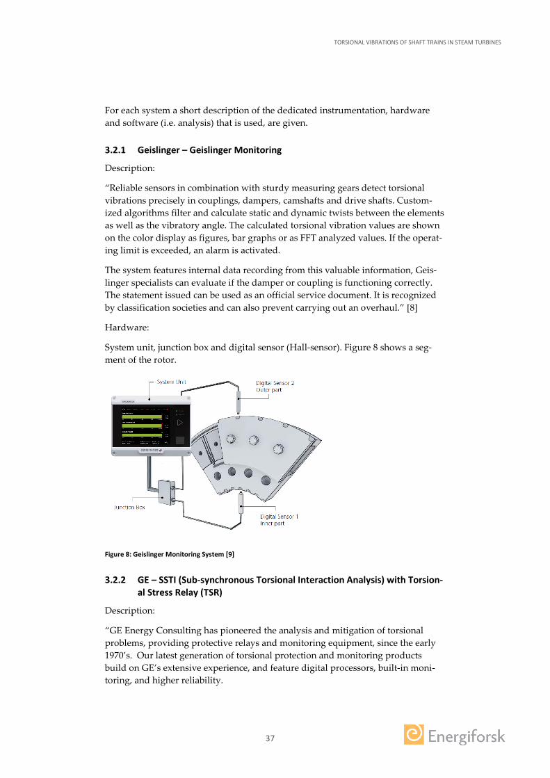
Hardware:
System unit, junction box and digital sensor (Hall-sensor). Figure 8 shows a seg-ment of the rotor.
Figure 8: Geislinger Monitoring System [9]
3.2.2 GE – SSTI (Sub-synchronous Torsional Interaction Analysis) with Torsion-al Stress Relay (TSR)
Description:
“GE Energy Consulting has pioneered the analysis and mitigation of torsional problems, providing protective relays and monitoring equipment, since the early 1970’s. Our latest generation of torsional protection and monitoring products build on GE’s extensive experience, and feature digital processors, built-in moni-toring, and higher reliability.
TORSIONAL VIBRATIONS OF SHAFT TRAINS IN STEAM TURBINES
38
The Torsional Stress Relay (TSR) is a digital protective relay that continuously monitors the turbine generator shaft for torsional oscillations, and provides trip output contacts when shaft fatigue reaches predetermined levels. Torsional event data capture is also provided.
The TSR is an updated digital version of the proven GE SMF relay. GE technology has been used since 1976 to protect turbine-generators exposed to risk of harmful torsional interaction.
Subsynchronous Resonance caused by series capacitors is the most common reason that torsional protection may be needed.
Torsional protection may also be required for high rated power electronic convert-ers that are near to turbine-generators. HVDC is especially of concern, due to typi-cally high power ratings. Large motor drives and SVC can also be a problem, typi-cally for smaller turbine-generators nearby. Energy Consulting can perform a simple Subsynchronous Torsional Interaction (SSTI) screening study in these cases.
Subsynchronous Resonance or Subsynchronous Torsional Interaction may, in rare cases, require active damping or resonance blocking filters to protect high value capital equipment. [10]
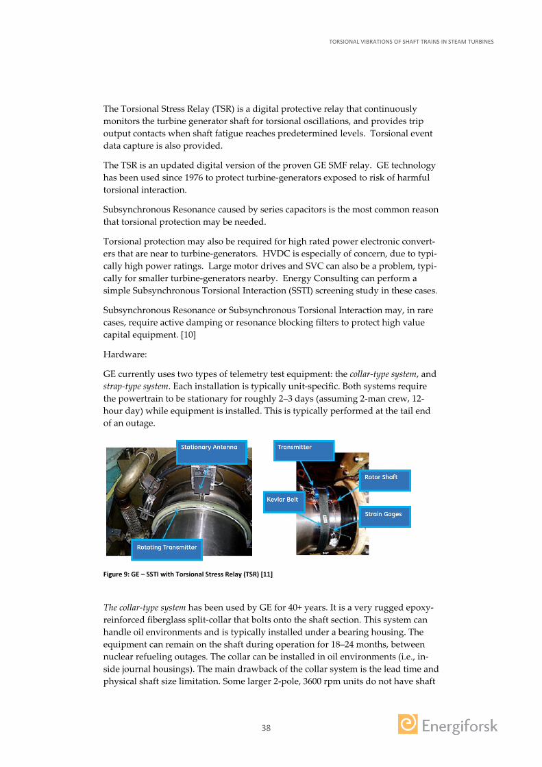
Hardware:
GE currently uses two types of telemetry test equipment: the collar-type system, and strap-type system. Each installation is typically unit-specific. Both systems require the powertrain to be stationary for roughly 2–3 days (assuming 2-man crew, 12-hour day) while equipment is installed. This is typically performed at the tail end of an outage.
Figure 9: GE – SSTI with Torsional Stress Relay (TSR) [11]
The collar-type system has been used by GE for 40+ years. It is a very rugged epoxy-reinforced fiberglass split-collar that bolts onto the shaft section. This system can handle oil environments and is typically installed under a bearing housing. The equipment can remain on the shaft during operation for 18–24 months, between nuclear refueling outages. The collar can be installed in oil environments (i.e., in-side journal housings). The main drawback of the collar system is the lead time and physical shaft size limitation. Some larger 2-pole, 3600 rpm units do not have shaft

TORSIONAL VIBRATIONS OF SHAFT TRAINS IN STEAM TURBINES
39
sections small enough to allow installation of the collar-type system. Slower speed 4-pole units typically do not have size limitations.
The strap-type system was developed as a more modern version of the torsional testing system that can be used to respond quickly to a customer’s needs. The sys-tem uses updated wireless electronics to transmit the signal along with a different physical mounting arrangement. This system uses a small transmitter (2”x 2”x ½”) that is held to the rotor with a Kevlar® belt. Due to the high strength-to-weight ratio of the belt, this system can handle significantly larger shaft sizes for 2 pole units (3000/3600 rpm). The belts can be quickly produced and are sometimes in stock, providing much shorter lead times. The strap system has two drawbacks. First, the equipment cannot operate in an oil environment. Second, the system needs to be removed within two months of operation, since the belt is not intended for long-term operation. Removing the system can be done rather quickly, typically in the same time it takes to install or remove a balance shot.” [10]
3.2.3 TAM – Torque And More
Description:
“The A3 Sensor can be used with any Ferro-magnetic Test-Object (e.g. solid shaft, hollow tube, beam) and measures Torque, Bending, and Axial Load forces. This is Plug-and-Play technology: Mount the A3 Sensing Module nearest to the Test-Object, switch on electric power, initialize and measure immediately. The Active-3 technology can be applied to volume applications and is also available as an A3 Sensor Kit for laboratory-use and test applications.” [12]
Hardware:
Sensing Module, Sensor Electronics, Power Supply, Software and Cable
Figure 10: TAM – System [12] [13]
3.2.4 Siemens – LMS Test. Lab Torsional vibration analysis
Description:
• Integrated hardware and software solution dedicated to powertrain engineer-ing
• LMS testing solutions for powertrain engineering provide in-depth insight • Measuring all attributes from LMS SCADAS™ hardware and processing them
with a common LMS Test.Lab™ software platform.
TORSIONAL VIBRATIONS OF SHAFT TRAINS IN STEAM TURBINES
40
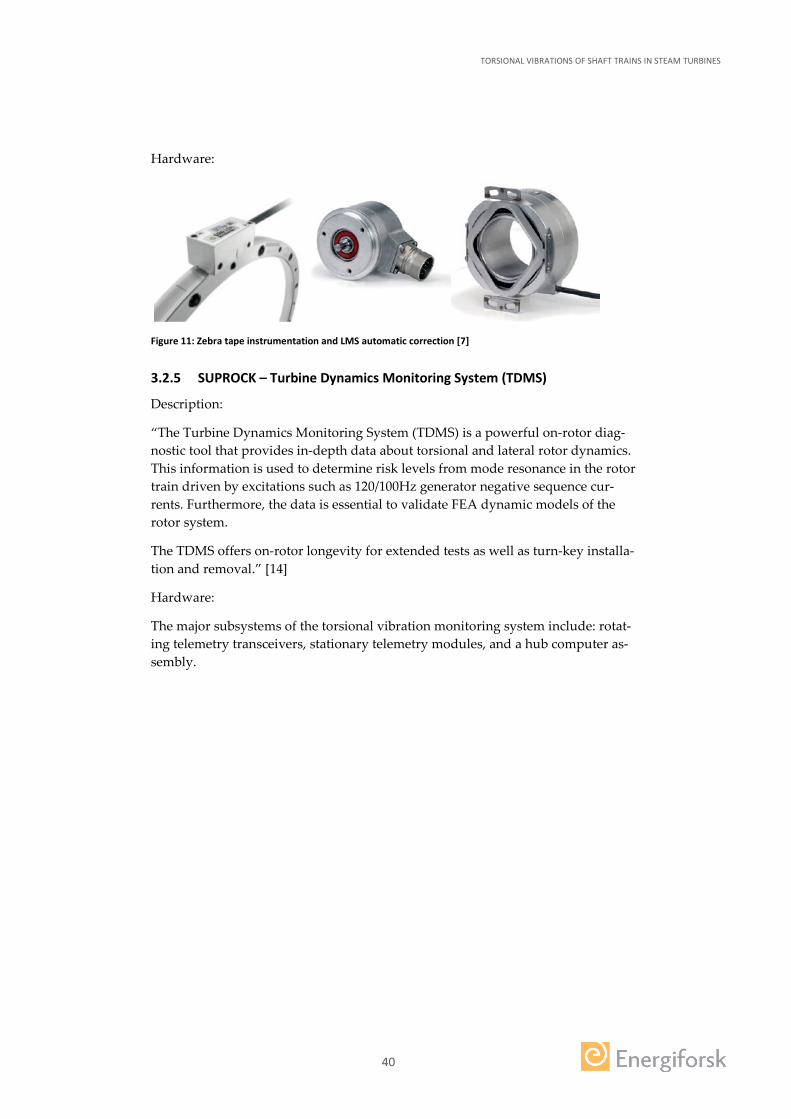
Hardware:
Figure 11: Zebra tape instrumentation and LMS automatic correction [7]
3.2.5 SUPROCK – Turbine Dynamics Monitoring System (TDMS)
Description:
“The Turbine Dynamics Monitoring System (TDMS) is a powerful on-rotor diag-nostic tool that provides in-depth data about torsional and lateral rotor dynamics. This information is used to determine risk levels from mode resonance in the rotor train driven by excitations such as 120/100Hz generator negative sequence cur-rents. Furthermore, the data is essential to validate FEA dynamic models of the rotor system.
The TDMS offers on-rotor longevity for extended tests as well as turn-key installa-tion and removal.” [14]
Hardware:
The major subsystems of the torsional vibration monitoring system include: rotat-ing telemetry transceivers, stationary telemetry modules, and a hub computer as-sembly.

TORSIONAL VIBRATIONS OF SHAFT TRAINS IN STEAM TURBINES
41
Figure 12: SUPROCK – TDMS System [14] [15]
3.3 COMPARISON OF COMMERCIAL SYSTEMS
In Table 13 a comparison of the available commercial systems is given.
Table 13: Comparison of commercial torsional vibrations monitoring systems
Company Product Name
Measure-ment Method
Mounting Type
Measured Values
Annota-tion
Geislinger Geisling-er Moni-toring
Coder based Hall-sensors
Sensors posi-tioned close to wheels with grooves or angle encod-ers
Torque and vibra-tory angle
Price ca. 9000 € + mounting and adap-tation n ≤ 1500 rpm
GE TSR Torsional Stress Relay
Direct strain gauges
Strain gauges attached to shaft collar-type or strap-type
Torque
Price de-pending on system and adap-tation
Torque and More
Ad-vanced
Coder Based
Non-contact Plug-and-Play
Torque ca. 9000 €

TORSIONAL VIBRATIONS OF SHAFT TRAINS IN STEAM TURBINES
42
Company Product Name
Measure-ment Method
Mounting Type
Measured Values
Annota-tion
Active-3 Torque Sensors
Hall-sensors
Ferro-magnetic shaft material required
Siemens LMS Test.Lab
Coder Based N/A
Depends on selected sen-sors
Depends on select-ed sensors
Price de-pending on system and adap-tation
Suprock-tech
TDMS (Turbine Dynam-ics Moni-toring System)
Direct Strain gauges and accel-erometers
Mounted on shaft
Torsional and also lateral dynamics
Price de-pending on system and adap-tation

TORSIONAL VIBRATIONS OF SHAFT TRAINS IN STEAM TURBINES
43
4 Mitigation Measures
This chapter deals with potential mitigation measures, which are suitable for han-dling torsional vibrations. They are split into mitigation procedures (chapter 4.1) and commercially available mitigation systems (chapter 4.1.8). In the description of each mitigation measure the fault, for which the procedure is applicable is named including the reference to the specific root cause. Table 14 in chapter 4.1.8 gives an overview over currently available torsional vibration dampers.
4.1 MITIGATION PROCEDURES
This chapter describes possible procedures for mitigating torsional vibrations. Note that these mitigation procedures might already be part of the baseline design, i.e. precautions were already taken to avoid the excitation of natural torsional fre-quencies (see chapter 2.4). These procedures were partially found in the context of literature researches.
4.1.1 Modifications to Shift a Torsional Frequency
This procedure is applicable for all root causes that excite torsional natural fre-quencies of the steam turbine e.g. by SSR.
An excitable mode with a frequency too close to an exciting torque frequency can be shifted away from the problem frequency. This is possible by changing the polar moment of inertia e.g. by installing a shrunk-on ring on a coupling. Another possi-bility is to change the stiffness of the shaft(s) and/or the frequency of the turbine blade stages. LP turbine discs that support blades might also be re-machined to aid the frequency detuning. In cases where shifting the frequency of modes is neces-sary, it is mandatory to have a well calibrated calculation model of the complete turbine-generator. Design change options can then be evaluated analytically for their effectiveness with reasonable confidence and without shifting another natural frequency into the problem range.
Figure 13 shows an example of a calculated shift in frequencies that were predicted for an actual 4P turbine-generator. That was done by changing the polar moment of inertia of the “C” coupling between the LPB turbine rotor and the generator rotor. Calculations indicated that this was the most effective location to change the inertia of the machine to achieve the required detuning result. It is seen that im-provements to the mode of concern could be made by removing or adding inertia at the “C” coupling to shift mode 25 away from the critical 120 Hz (2xN). A shrunk-on ring to the coupling outside diameter increases its polar moment of inertia. [4]

TORSIONAL VIBRATIONS OF SHAFT TRAINS IN STEAM TURBINES
44
Figure 13: Calculated Effect on Torsional Frequencies of Adding Mass to a Coupling
4.1.2 Delay in High Speed Reclosing HSR
Applicable for “Transmission line short circuits”, see RC 2.1.
There are several alternate power circuit breaker operating practices in use follow-ing electrical faults. These may reduce transmission system reliability objectives but could provide an overall power generation/transmission reliability benefit by reducing substantially the torsional duty on turbine-generators. These practices include:
• Having equipment that delays reclosing by several seconds to allow decay of shaft oscillations and avoid shaft torque compounding effects.
• Employing sequential reclosing equipment. The breaker re-closure is done initially from the end of the transmission line “remote” to the turbine-generator(s). Also HSR (high speed reclosing) is then blocked from occurring at the power station end of the transmission line if the initiating electrical fault persists.
• Employing equipment that senses the type of electrical fault occurring. It blocks HSR for the especially severe types of faults that could potentially dam-age the turbine generator(s). E.g. “permanent” multi-phase faults do not need HSR. [4]
4.1.3 Defined Step Change
Applicable for “Planned or Emergency Line Switching Operations”, see RC 2.2.
For planned line switching incidents, an IEEE (Institute of Electrical and Electron-ics Engineers) guideline exists for power system planners to use. It is applied on the level of the step change in power or current seen by a machine (in per unit of its output). It is generally undamaging and avoids the need for a special screening study to be performed. [4]
TORSIONAL VIBRATIONS OF SHAFT TRAINS IN STEAM TURBINES
45
4.1.4 Selective Transpositions of transmission lines
Applicable for “Unbalanced Phase Currents in the Grid”, see RC 2.3.
In most cases the utility companies attempt to keep the connected loads on the distribution lines balanced as well as possible. If the transmission lines were uni-formly transposed throughout their entire length, the impedance of each line would theoretically be equal. Transpositions though complicate the physical con-struction of a line and also constitute increased risk of phase to phase faults. Transposing transmission lines is consequently done selectively for the longer ones. [4]
4.1.5 Harmonic Filters
Applicable for “Application of Power Electronics”, see RC 2.4.
Harmonic filters are used to eliminate the current harmonics. However, if these filters do not perform as designed, other than 50 Hz (resp. 60 Hz) currents will be introduced into the grid which can then enter the generator armature. [4]
4.1.6 Unit Interaction Factor (UIF)
Applicable for “Turbine-Generator Device Dependent Subsynchronous Oscilla-tions (DDSO) with DC Power Converters”, see RC 1.3.
A screening procedure for the case of line commutated HVDC converters has been developed to determine the potential for DDSO to occur using a parameter called the “Unit Interaction Factor” (UIF).
If the UIF value is less than 0.1, then a detailed assessment is unnecessary, based on experience.
For the newer type of HVDC systems using voltage source converters, a “UIF” value much less than 0.1 may require detailed assessment. The electrical mecha-nism by which DDSO occurs is phase-shift modulation of the power system AC voltage waveform. Phase-shift modulation means the basic waveform remains the same in amplitude and average frequency, but the phase-angle continuously varies about its nominal or steady-state value. [4]
4.1.7 Rapid Acceleration through Critical Speeds
Applicable for “Variable Frequency Electric Drives”, see RC 1.6.
The design of these coupled electrical machines has to be in a way that the torsion-al natural frequencies are calculated and modified as required to avoid high reso-nant type response levels from being developed at part load/speed conditions and during speed excursions.
Operational strategies include rapid acceleration through defined torsional critical speeds and avoidance of operation hold points near these speeds. [4]
TORSIONAL VIBRATIONS OF SHAFT TRAINS IN STEAM TURBINES
46
4.1.8 Automatic Turbine Trip
This procedure is applicable for all root causes.
The idea behind this procedure is to simply shut down the turbine as soon as the monitoring system reports the exceedance of a trip value. The major challenge of this procedure is to be in time with the shutdown.
4.2 COMMERCIAL MITIGATION SYSTEMS
4.2.1 Torsional Vibration Damper
Applicable to all Root Causes.
Torsional Vibration Dampers or Absorbers described in this chapter are not pre-venting a possible torsional vibration but they are counteracting against an existing one – independently from the root cause. This consequently means that the root cause has not to be evaluated in detail. Therefore no references to specific RCs are made in this chapter.
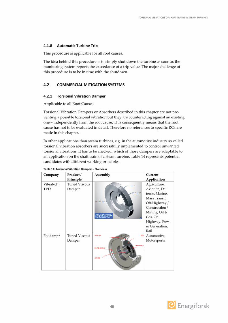
In other applications than steam turbines, e.g. in the automotive industry so called torsional vibration absorbers are successfully implemented to control unwanted torsional vibrations. It has to be checked, which of those dampers are adaptable to an application on the shaft train of a steam turbine. Table 14 represents potential candidates with different working principles.
Table 14: Torsional Vibration Dampers - Overview
Company Product / Principle
Assembly Current Application
Vibratech TVD
Tuned Viscous Damper
Agriculture, Aviation, De-fense, Marine, Mass Transit, Off-Highway / Construction / Mining, Oil & Gas, On-Highway, Pow-er Generation, Rail
Fluidampr Tuned Viscous Damper
Automotive, Motorsports

TORSIONAL VIBRATIONS OF SHAFT TRAINS IN STEAM TURBINES
47
Company Product / Principle
Assembly Current Application
Schaeffler Dual Mass Fly-Wheel with CPA
Automotive
Hasse & Wrede
Visco-Damper and Hydraulic Damper
Automotive, industrial en-gine
ContiTech Torsional Vibration Damper
Automotive Flywheel
Belt pulley Damping elastomer track Sliding bearing Coupling
TORSIONAL VIBRATIONS OF SHAFT TRAINS IN STEAM TURBINES
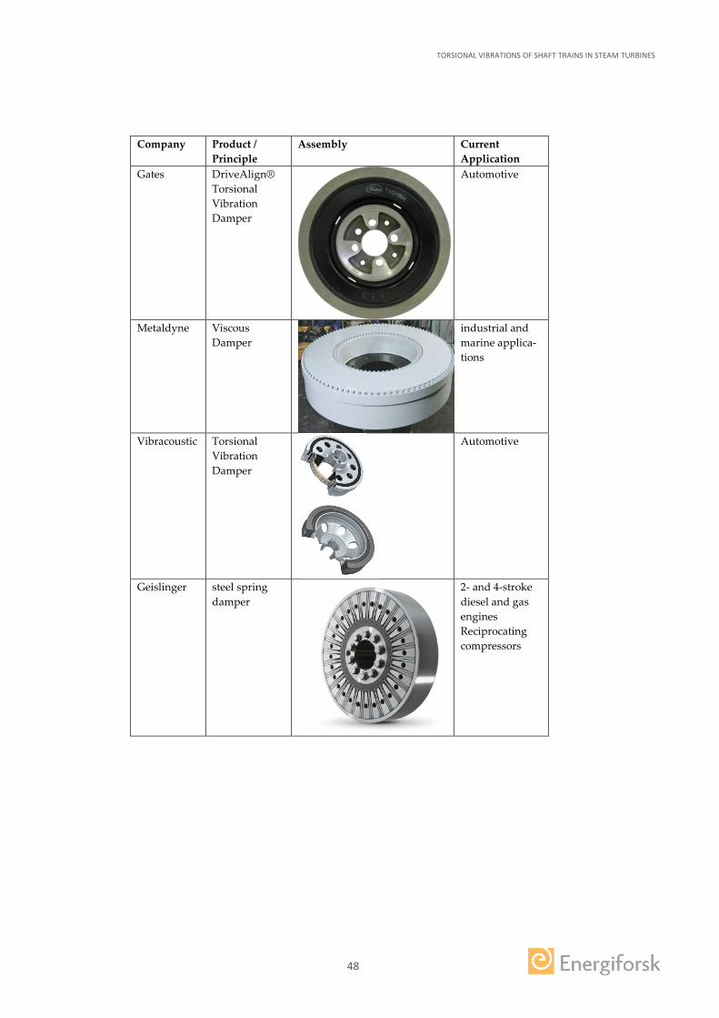
48
Company Product / Principle
Assembly Current Application
Gates DriveAlign® Torsional Vibration Damper
Automotive
Metaldyne Viscous Damper
industrial and marine applica-tions
Vibracoustic Torsional Vibration Damper
Automotive
Geislinger steel spring damper
2- and 4-stroke diesel and gas engines Reciprocating compressors

TORSIONAL VIBRATIONS OF SHAFT TRAINS IN STEAM TURBINES
49
4.3 SPECIAL MITIGATION SYSTEMS FOR SUBSYNCHRONOUS RESONANCE SSR
Following the shaft failures from SSR torsional interaction different countermeas-ures were developed for general SSR problems. These devices are aimed at mitigat-ing the harmful effects to the turbine-generator shafts of subsynchronous currents emanating in the transmission system. A supplier of those systems cannot be found directly. Systems are described in [16] and include the following remedial treatments:
4.3.1 SSR filters in power transformer
Applicable for “Subsynchronous Resonances (SSR)”, see RC 1.1.
The approach is to insert a subsynchronous filter at the neutral of the main power transformer. This solution, which would neither cause a decrease in the system transient stability limit, nor increase the likelihood of hunting (abnormal electro-mechanical condition), is very appealing.
It increases the needed insulation level of the transformer neutral BIL (Basic Im-pulse Insulation Level) but requires a large area of the substation. Furthermore, it practicality can be limited by its narrow bandwidth.
4.3.2 Supplementary Excitation Damper Control (SEDC)
Applicable for all Root Causes.
“This technique consists of injecting a properly phased sinusoidal signal into the voltage regulator. This signal is derived from the rotor motion by sensors.” [16]
Basically this describes an early (1977) active vibration control system, following the feedforward approach. The properly phased sinusoidal signal is injected into the control of the generator, which then counteracts against unwanted torsional vibrations.
4.3.3 Static VAR compensators (SVC)
Applicable for “Transmission Line Short Circuits” and “Planned or Emergency Line Switching Operations”, see RC 2.1 and RC 2.2.
Static Var Compensators (SVCs) are devices that can quickly and reliably control line voltages. An SVC will typically regulate and control the voltage to the re-quired set point under normal steady state and contingency conditions and there-by provide dynamic, fast response reactive power following system contingencies (e.g. network short circuits, line and generator disconnections). In addition, an SVC can also increase transfer capability, reduce losses, mitigate active power oscilla-tions and prevent over voltages at loss of load. [17]
4.3.4 Superconducting magnetic storage units (SMES)
Applicable to all Root Causes that cause transient excitations, e.g. RC 2.1, RC 2.2, RC 2.6 and RC 2.7.

TORSIONAL VIBRATIONS OF SHAFT TRAINS IN STEAM TURBINES
50
SMES is a grid-enabling device that stores and discharges large quantities of power almost instantaneously. The system is capable of releasing high levels of power within a fraction of a cycle to replace a sudden loss or dip in line power. Strategic injection of brief bursts of power can play a crucial role in maintaining grid relia-bility. This is especially due to today’s increasingly congested power lines and the high penetration of renewable energy sources, such as wind and solar.
A typical SMES consists of two parts – cryogenically cooled superconducting coil and power conditioning system – which are motionless and result in higher relia-bility than many other power storage devices. Ideally, once the superconducting coil is charged, the current will not decay and the magnetic energy can be stored indefinitely. [18]
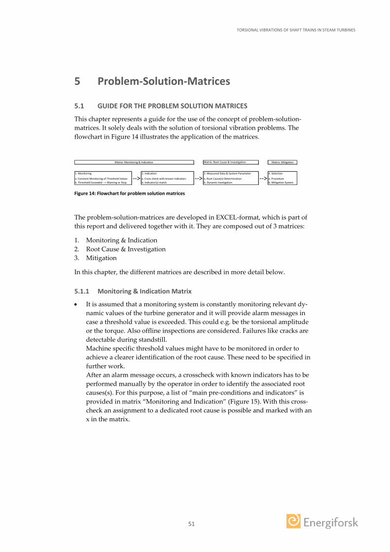
TORSIONAL VIBRATIONS OF SHAFT TRAINS IN STEAM TURBINES
51
5 Problem-Solution-Matrices
5.1 GUIDE FOR THE PROBLEM SOLUTION MATRICES
This chapter represents a guide for the use of the concept of problem-solution-matrices. It solely deals with the solution of torsional vibration problems. The flowchart in Figure 14 illustrates the application of the matrices.
Figure 14: Flowchart for problem solution matrices
The problem-solution-matrices are developed in EXCEL-format, which is part of this report and delivered together with it. They are composed out of 3 matrices:
1. Monitoring & Indication 2. Root Cause & Investigation 3. Mitigation
In this chapter, the different matrices are described in more detail below.
5.1.1 Monitoring & Indication Matrix
• It is assumed that a monitoring system is constantly monitoring relevant dy-namic values of the turbine generator and it will provide alarm messages in case a threshold value is exceeded. This could e.g. be the torsional amplitude or the torque. Also offline inspections are considered. Failures like cracks are detectable during standstill. Machine specific threshold values might have to be monitored in order to achieve a clearer identification of the root cause. These need to be specified in further work. After an alarm message occurs, a crosscheck with known indicators has to be performed manually by the operator in order to identify the associated root causes(s). For this purpose, a list of “main pre-conditions and indicators” is provided in matrix “Monitoring and Indication” (Figure 15). With this cross-check an assignment to a dedicated root cause is possible and marked with an x in the matrix.
Matrix: Root Cause & Investigation Matrix: Mitigation
1. Monitoring 2. Indication 3. Measured Data & System Parameter 4. Selection
a. Constant Monitoring of Threshold Values --> a. Cross check with known Indicators --> a. Root Cause(s) Determination --> a. Procedureb. Threshold Exceeded --> Warning or Stop b. Indicator(s) match b. Dynamic Inestigation b. Mitigation System
Matrix: Monitoring & Indication

TORSIONAL VIBRATIONS OF SHAFT TRAINS IN STEAM TURBINES
52
Figure 15: Monitoring & Indication Matrix
5.1.2 Root Cause & Investigation Matrix
• In matrix “Root Cause & Investigation” (Figure 16) the identified indication from the “Monitoring and Indication matrix” is assigned to a dedicated root cause. The matrix solely shows a list of these root causes as a basis for finding an appropriate mitigation system.
• For some mitigation approaches it is mandatory to have special knowledge about the dynamic characteristics of the drive shaft. In detail these are the ones described in the chapters 4.1.1, 4.1.5, 4.1.7, 4.2.1, 4.3.1 and 4.3.2. For this pur-pose either the necessary knowledge is already available or an investigation of this knowledge on the dynamic characteristics of the shaft train has to be estab-lished in the framework of an investigation. If this is – for any reason – not possible, the variety of mitigation approaches is limited to the procedures that mitigate without a need of dedicated knowledge or investigation about the
Dete
ctio
ns
Tors
iona
l Am
plitu
de
Torq
ue V
alue
Crac
ks b
y Fr
ettin
g
Crac
ks b
y Hi
gh C
ycle
Fat
igue
Ambi
ent T
empe
ratu
re
Radi
atio
n
Cond
uctiv
ity
Flow
rate
mon
itorin
g
Pres
sure
mon
itorin
g
Indication # Main pre-conditions & indicators*Report section
3 3
2.6.
1
2.6.
1
Ind. 1 RLC circuit resonance for long distance transmission RC 1.1
Ind. 2 Turbine connected to HVDC transmission line AND AC/DC power convertrers RC 1.2
Ind. 3 Rating of the converter, which is similar to turbine-generators RC 1.2
Ind. 4Power rectifier installation to convert the alternating currents produced by turbine-generators
RC 1.3
Ind. 5 Back-to-back DC terminals to electrically isolate two AC transmission systems RC 1.3
Ind. 6Presence of near by AC arc furnaces with large load fluctuations e.g. by arc/melt process.
RC 1.4
Ind. 7 Near by mini steel mills using arc furnaces RC 1.5
Ind. 8Variable-frequency-electric-drives for large compressor, pump, blower applications close to steam turbine-generators.
RC 1.6
Ind. 9Lightning surge or subsequent dielectric breakdown between one phase and ground causing short circuits
RC 2.1
Ind. 10 Initiation of high speed reclosing (HSR) RC 2.1Ind. 11 Transmission lines taken out of and put back into service. RC 2.2Ind. 12 Three-phase currents of transmission system getting unbalanced RC 2.3Ind. 13 Negative sequence currents entering the generator armature RC 2.3
Ind. 14
Power electronics inducing current vibrations, e.g.- combustion air fans- rolling mills (at steel mills)- DC arc furnaces- HVDC convertrers
RC 2.4
Ind. 15 Faults on equipment connected to turbine-generator RC 2.5Ind. 16 Overspeeding of turbine shaft RC 2.5Ind. 17 Mal-synchronization of turbine-generator to transmission network RC 2.6Ind. 18 Isolated turbine-generator from power system RC 2.7
Ind. 19Synchronism-Loss of turbine-generators between each other on one power system
RC 2.8
Ind. 20 Retaining ring fretting / fracture RC 1.3
Ind. 21 High Blade vibrations / cracksRC 1.3RC 2.3RC 2.7
Torsional Vibration
Monitoring ALARM
System Monitoring ALARM
Offline Inspecti
on
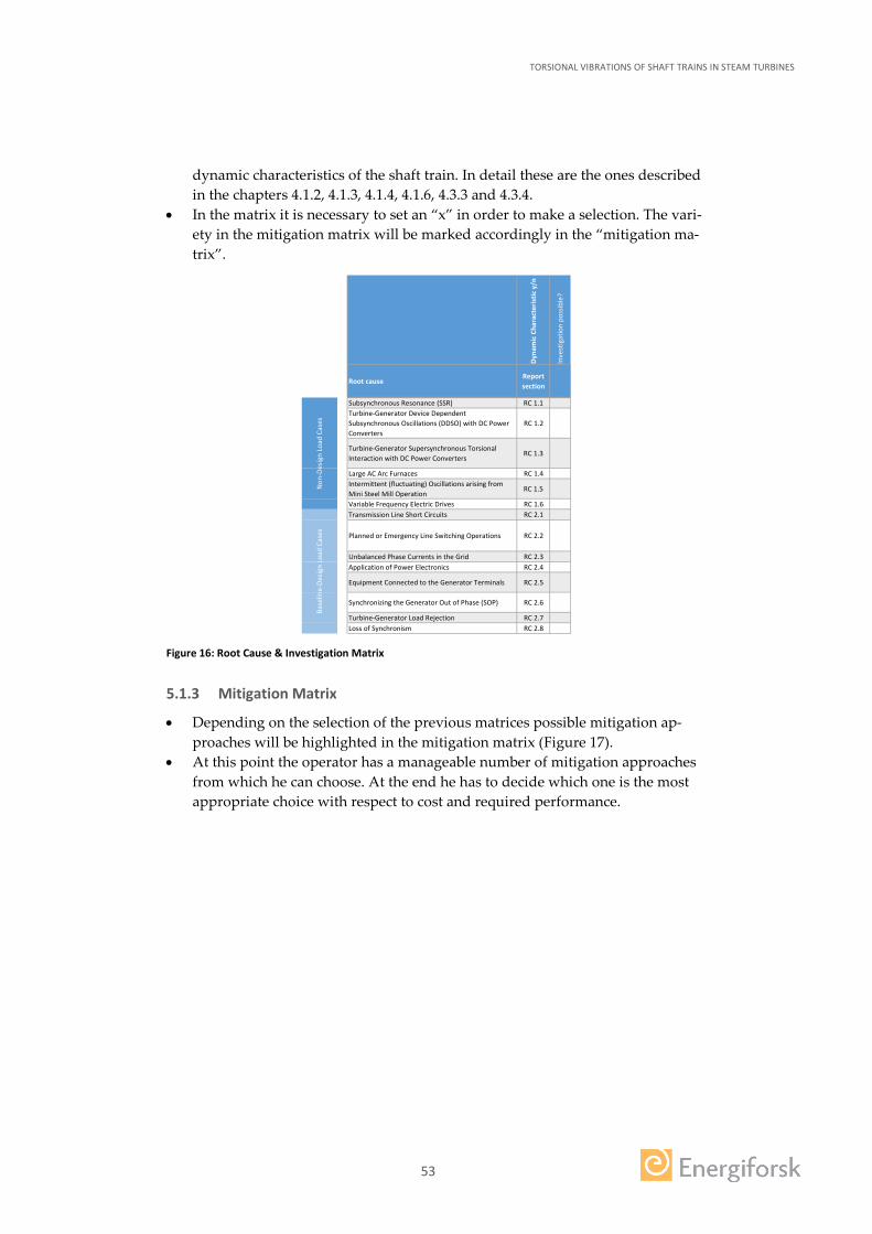
TORSIONAL VIBRATIONS OF SHAFT TRAINS IN STEAM TURBINES
53
dynamic characteristics of the shaft train. In detail these are the ones described in the chapters 4.1.2, 4.1.3, 4.1.4, 4.1.6, 4.3.3 and 4.3.4.
• In the matrix it is necessary to set an “x” in order to make a selection. The vari-ety in the mitigation matrix will be marked accordingly in the “mitigation ma-trix”.
Figure 16: Root Cause & Investigation Matrix
5.1.3 Mitigation Matrix
• Depending on the selection of the previous matrices possible mitigation ap-proaches will be highlighted in the mitigation matrix (Figure 17).
• At this point the operator has a manageable number of mitigation approaches from which he can choose. At the end he has to decide which one is the most appropriate choice with respect to cost and required performance.
Dyna
mic
Cha
ract
eris
tic y
/n
Inve
stig
atio
n po
ssib
le?
Root causeReport section
Subsynchronous Resonance (SSR) RC 1.1Turbine-Generator Device Dependent Subsynchronous Oscillations (DDSO) with DC Power Converters
RC 1.2
Turbine-Generator Supersynchronous Torsional Interaction with DC Power Converters
RC 1.3
Large AC Arc Furnaces RC 1.4Intermittent (fluctuating) Oscillations arising from Mini Steel Mill Operation
RC 1.5
Variable Frequency Electric Drives RC 1.6Transmission Line Short Circuits RC 2.1
Planned or Emergency Line Switching Operations RC 2.2
Unbalanced Phase Currents in the Grid RC 2.3Application of Power Electronics RC 2.4
Equipment Connected to the Generator Terminals RC 2.5
Synchronizing the Generator Out of Phase (SOP) RC 2.6
Turbine-Generator Load Rejection RC 2.7Loss of Synchronism RC 2.8
Base
line-
Desig
n Lo
ad C
ases
Non
-Des
ign
Load
Cas
es
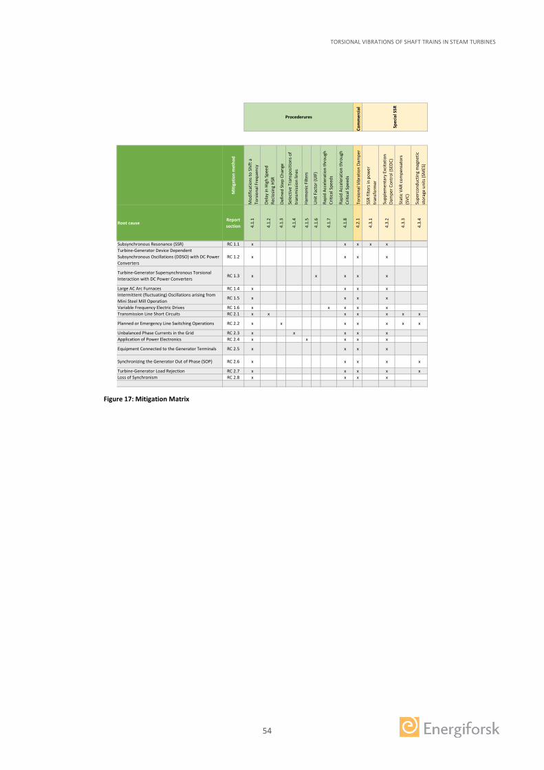
TORSIONAL VIBRATIONS OF SHAFT TRAINS IN STEAM TURBINES
54
Figure 17: Mitigation Matrix
Com
mer
cial
Miti
gatio
n m
etho
d
Mod
ifica
tions
to S
hift
a
Tors
iona
l Fre
quen
cy
Dela
y in
Hig
h Sp
eed
Recl
osin
g HS
R
Defin
ed S
tep
Chan
ge
Sele
ctiv
e Tr
ansp
ositi
ons o
f tr
ansm
issio
n lin
es
Harm
onic
Filt
ers
Uni
t Fac
tor (
UIF
)
Rapi
d Ac
cele
ratio
n th
roug
h Cr
itica
l Spe
eds
Rapi
d Ac
cele
ratio
n th
roug
h Cr
itica
l Spe
eds
Tors
iona
l Vib
ratio
n Da
mpe
r
SSR
filte
rs in
pow
er
tran
sfor
mer
Supp
lem
enta
ry E
xcita
tion
Dam
per C
ontr
ol (S
EDC)
Stat
ic V
AR c
ompe
nsat
ors
(SVC
)
Supe
rcon
duct
ing
mag
netic
st
orag
e un
its (S
MES
)
Root causeReport section 4.
1.1
4.1.
2
4.1.
3
4.1.
4
4.1.
5
4.1.
6
4.1.
7
4.1.
8
4.2.
1
4.3.
1
4.3.
2
4.3.
3
4.3.
4
Subsynchronous Resonance (SSR) RC 1.1 x x x x xTurbine-Generator Device Dependent Subsynchronous Oscillations (DDSO) with DC Power Converters
RC 1.2 x x x x
Turbine-Generator Supersynchronous Torsional Interaction with DC Power Converters
RC 1.3 x x x x x
Large AC Arc Furnaces RC 1.4 x x x xIntermittent (fluctuating) Oscillations arising from Mini Steel Mill Operation
RC 1.5 x x x x
Variable Frequency Electric Drives RC 1.6 x x x x xTransmission Line Short Circuits RC 2.1 x x x x x x x
Planned or Emergency Line Switching Operations RC 2.2 x x x x x x x
Unbalanced Phase Currents in the Grid RC 2.3 x x x x xApplication of Power Electronics RC 2.4 x x x x x
Equipment Connected to the Generator Terminals RC 2.5 x x x x
Synchronizing the Generator Out of Phase (SOP) RC 2.6 x x x x x
Turbine-Generator Load Rejection RC 2.7 x x x x xLoss of Synchronism RC 2.8 x x x x
Spec
ial S
SR
Procederures
TORSIONAL VIBRATIONS OF SHAFT TRAINS IN STEAM TURBINES
55
6 Conclusion and Future Work
6.1 CONCLUSION
This report deals with torsional vibrations in shaft trains of steam turbines in-stalled in nuclear power plants. It can be concluded that in any of the above men-tioned items enough knowledge is collected to use it for solving potential problems related to torsional vibrations in shaft trains.
The report gives overviews on
• general aspects and the motivation for this report, • different known root causes, • a collection of practical experiences and incidents, • means of measurement and identification and • possible mitigations measures.
Appendix A of the report is represented by an Excel-File “Appendix A - Prob-lem_Solution_Matrix.xls”, which contains the conceptional problem solution ma-trices to be used as an instruction to solve the torsional vibration problems. It basi-cally shall guide the operator through the process all the way from problem identi-fication to the mitigating system. As an instruction for the problem solution matri-ces a flow chart is added that explains the different necessary steps to be taken during the problem solution process. The problem solution matrix is to be regard-ed as a living document, which can be updated if required.
6.2 FUTURE WORK
Some items of this report need further attention and processing. Those items are listed below and are recommended to be developed further on in the framework of a follow-up project:
• Applicability of torsional vibration dampers for steam turbines. • Development of root cause analysis derived from
× measured data of torsional monitoring (and others), × actual system parameters and × machine specific threshold values.
• Further development of the problem solution matrices.

TORSIONAL VIBRATIONS OF SHAFT TRAINS IN STEAM TURBINES
56
7 List of abbreviations
1xN 1 times grid frequency
2xN 2 times grid frequency
2P 2-pole
4P 4-pole
DDSO Device Dependent Subsynchronous Oscillations
DC Direct Current
FFT Fast Fourier Transform
FEA Finite Element Analysis
GE General Electric
GEN Generator
HCF High Cycle Fatigue
HSR High Speed Reclosing
HVDC High Voltage DC
IEEE Institute of Electrical and Electronics Engineers
ISO International Standards Organization
LPB Low Pressure Turbine
NPP Nuclear power plant
PLM Product Lifecycle Management
RC Root Cause
RLC Resistance, Inductance, Capacitance
RPM Revolution Per Minute
SEDC Supplementary Excitation Damper Control
SMES Superconducting Magnetic Storage Units
SOP Synchronizing the Generator Out of Phase
SSR Sub-Synchronous Resonances
SSTI Sub-Synchronous Torsional Interaction Analysis
SVC Static VAR Compensator
TAM Torque And More
TBD To Be Defined
TSR Torsional Stress Relay
TDSM Turbine Dynamic Monitoring System

TORSIONAL VIBRATIONS OF SHAFT TRAINS IN STEAM TURBINES
57
8 List of references
[1] A. Lokhov, R. Cameron, M. Cometto and H. Ludwig, "Technical and Economical
Aspects of Load Following with Nuclear Power Plants," 2011. [Online]. Available: http://www.oecd-nea.org/ndd/reports/2011/load-following-npp.pdf. [Accessed 7 July 2017].
[2] K. W. Jan-Erik Bengtsson, A Method of Analysis of Subsynchronous Resonances, The Swedish State Power Board, 1981.
[3] P. R. Nordmann, "Turbine and Generator Vibrations," in ENERGIFORSK Vibration Group Seminar: Vibrations in Nuclear Applications, Stockholm, Sweden, October 4th 2016.
[4] D. N. Walker, "Steam Turbine-Generator Torsional Vibration Interaction with the Electrical Network: Tutorial," Electric Power Research Institute (EPRI), Palo Alto, 2005.
[5] International Organization for Standardization, ISO/FDIS 22266-1:2016(E), Mechanical vibration - Torsional vibration of rotating machinery - Part 1: Land-based steam and gas turbine generator sets in excess of 50 MW, 2016.
[6] ENERGIFORSK, Data and information provided by members of Energiforsk, Feb. to July , 2017.
[7] Siemens, "Identifying best practices for measuring and analyzing torsional vibration - White paper," Siemens PLM Software, 2014.
[8] Geislinger GmbH, "Geislinger Monitoring System," [Online]. Available: http://www.geislinger.com/en/products. [Accessed 30 June 2017].
[9] Geislinger GmbH, Monitoring Catalog Version 5.4, Austria, 2016. [10] General Electric, "GE - Global Power Projects - SSTI," [Online]. Available:
http://www.geenergyconsulting.com/practice-area/global-power-projects/sub-synchronous-torsional-interaction-analysis-and-risk-mitigation. [Accessed 30 June 2017].
[11] GE Power & Water, "Torsional Dynamics - Large 2-pole and 4-pole Steam Turbine Powertrains," May 2013. [Online]. Available: https://powergen.gepower.com/content/dam/gepower-pgdp/global/en_US/documents/technical/ger/ger-4724-torsional-dynamics-large-2-and-4-pole-steam-turbine-powertrains.pdf. [Accessed 03 July 2017].
[12] Torque and More GmbH, "Plug-and-Play Torque Sensor Kit: Active-3 Technology," [Online]. Available: http://www.tam-sensors.com/wp-content/uploads/A3-Introduction_V3.3.pdf. [Accessed 30 June 2017].
[13] Torque and More GmbH, "Torque Sensing: Anytime & Everywhere V2.7," 2016. [Online]. Available: http://www.tam-sensors.com/wp-content/uploads/TAMBook2016_druck.pdf. [Accessed 30 June 2017].
[14] Suprocktech, "Engineering - Power Generation," [Online]. Available: http://suprocktech.com/engineering/power.html. [Accessed 30 June 2017].
[15] Suprocktech, "TDMS Gallery," [Online]. Available: http://turbinedms.com/gallery.html. [Accessed 30 June 2017].
[16] K. Touy Khu, Subsynchronous resonance in power systems: damping of torsinal ascillations, Iowa: Iowa State University, 1977.

TORSIONAL VIBRATIONS OF SHAFT TRAINS IN STEAM TURBINES
58
[17] ABB, “http://new.abb.com/facts/static-var-compensation-(svc),” ABB, 2017. [Online]. Available: http://new.abb.com/facts/static-var-compensation-(svc).
[18] Super Power Inc., “http://www.superpower-inc.com/content/superconducting-magnetic-energy-storage-smes,” Super Power Inc., 2017. [Online]. Available: http://www.superpower-inc.com/content/superconducting-magnetic-energy-storage-smes.
[19] Energiforsk, "RFQ for Torsional Vibration in Shaft Trains," Stockholm, Sweden, November 2016.
[20] A. Lokhov, “Load-following with nuclear power plants,” NEA News, no. 29.2, pp. 18-20, 2011.
[21] K. Janssens and L. Britte, "Comparison of torsional vibration measurement techniques," in Proceedings of ISMA 2012 - USD 2012, Leuven, Belgium, 2012.


TORSIONAL VIBRATIONS IN STEAM TURBINE SHAFT TRAINSThis report deals with torsional vibrations in shaft trains, describing possible root causes and existing vibrational design criteria.
A collection of practical experiences related to torsional vibrations in shaft trains is given. It also presents different kinds of measurement methods and deals with potential measurement & monitoring systems.
Furthermore, an overview on mitigation measures, which are divided in procedures and commercial systems, is given. Finally, a guide for conceptually detecting and solving torsional vibration problems is pro-vided.
Energiforsk is the Swedish Energy Research Centre – an industrially owned body dedicated to meeting the common energy challenges faced by industries, authorities and society. Our vision is to be hub of Swedish energy research and our mission is to make the world of energy smarter!