Embed Size (px)
Citation preview
77LLuuKK SSYYMMPPOOSSIIUUMM 22000066
Torque converters –Comfort and fuel economyin tight corners
Marc McGrathJeff HemphillGeorge BaileyPhilip GeorgeMike SwankThorsten Krause

The torque converter celebrated its 100th birth-day in 2005. Invented in 1905 in Stettin, Ger-many, by Dr. Hermann Föttinger of the VulcanShip Yards, the torque converter was originally asteam turbine drive for a ship propeller. It gra-dually found its way into the mainstream auto-motive industry over the following 25 years. Thebook Changing Gears [1] shows a Lysholm-Smithtransmission with a torque converter and directdrive feature designed in 1928, which containsthe basic functions of today's lock-up torqueconverters. Torque converters of today look sim-ilar, but they have undergone continuous refine-ment through the years that have paralleled thedevelopment of the automobile, and theseimprovements continue.
Since the early days of the automobile, therehave been consistent trends towards better fueleconomy, higher horsepower, and lighter, morecompact drivetrains. Trends that are more recentare for example cylinder deactivation, dieselengines, and hybrids. There is much speculationsurrounding which of these trends will prevail inthe future. In the near term, however, it appearsthat each fills a niche due to varying legislativeand environmental pressures in different regions.
The United States Federal Motor Vehicle Act of1960 mandated federal research to address vehi-cle emissions, and in 1961 California mandatedpositive crankcase ventilation. Since that time
emissions laws have become more stringent andautomakers have continually evaluated conceptsaimed at lowering emissions. Today, directinjection diesel engines have provided not onlyfuel economy benefits, but emission benefits aswell. Hybrid vehicles use their engines lesshence they are lowering their emissions. Dieselsrepresent about half of the vehicles sold inEurope and they are gaining popularity in NorthAmerica. In the United States, consumer incen-tives in the 2005 Energy Bill could boost the pop-ularity of diesels and hybrids. The 2005 RicardoDiesel Report [2] predicts the U.S. market willexceed 1 million diesel units annually by 2012.
Although the torque converter has existed for acentury, there have been tremendous changes inthe most recent decade. As a major torque con-verter supplier, LuK has driven many of thesechanges. The torque converter developmentsdescribed in this article are the result of systemknowledge, which has enabled LuK to tailor thefluid circuit, TCC, and damper to a particularapplication.
The Shrinking BellhousingFor decades, suppliers have lamented the shrink-ing of the bell housing while the engine's torquecontinues to rise. A historical study of FrontWheel Drive transmissions shows that their complaints have some basis. Figure 1 records20 years of space versus torque history.
88 LLuuKK SSYYMMPPOOSSIIUUMM 22000066
11 TToorrqquuee ccoonnvveerrtteerrss
Introduction
Figure 1 History of axial space and torque

The 1985 installation space allowed 124 mm forthe toque converter with a generous clearancearound it. In this space it was possible to createa large round torus for good characteristics andfit a generous damper spring for good vibrationisolation. The picture in 1995 was similar withrespect to torque but dramatic with respect tospace. The largest possible converter was 94mmlong. This requires some rearranging of the inter-nal parts. In this case the torus was reduced insize and the damper spring was moved radiallyoutward. This is a better use of space and withmodern CFD and vibration simulation tools, thevehicle performance was not only maintainedbut also improved upon with respect to perform-ance and fuel economy.
The 2005 picture shows a healthy torque in-crease with a further dramatic reduction in axialspace. To meet this packaging challenge requireseither compromise or innovation. The fluid circuit could be further reduced in size and axial-ly squashed but fundamental physics dictatethat fluid flowing in a circle is more efficient. Atsome point, this squashing will result in fastrising k-factors and loss in converter efficiency,all of which effect fuel economy. Similarly, use ofexotic, high-stress coil spring wire and optimiza-tion of spring support can extend damper fun-ction, but at some point, isolation will be com-promised. Poor isolation leads to higher lock-upspeeds that also degrade fuel economy.
Many variations on the above themes have beentried successfully and continue to be developed atLuK and elsewhere. But through all these develop-ments, the stator and one-way clutch haveremained untouched and are now the axial spacebottleneck in the bellhousing. LuK has decided toaddress this previously “untouchable” need.
The Fluid CircuitThe stator has the simple function of turning thefluid flow, reflecting it back into the pump andthereby creating toque multiplication. Thedemands on this component have fallen as theindustry adopted 4, 5, and 6-speed transmis-sions. Since axial length must be reduced, a newstator paradigm is needed. The blade lengthcould be cut in half, if the number of blades isdoubled. Since, in this configuration, each bladebears only half the torque, the blade thickness
can be reduced as well. The comparison of theold and new paradigm is shown in figure 2.
This new profile lends itself to production withsheet metal stamping technology. Steel bladesalso have higher strength than aluminum or phe-nolic blades, allowing further reductions inblade thickness. Half of the blades are formed inone blank and the remaining half in another. Theplates are then placed around the one-wayclutch (OWC) and crimped or riveted together,forming an assembly.
The requirements for good retention and effi-ciency are still attainable in this configuration.The airfoil profile of the cast blades can beapproximated by coining, as is commonly donein impeller and turbine blades. One measuredcharacteristic is shown in figure 3, which demon-strates this capability (MP2000: pump torque at2000/min pump speed).
99LLuuKK SSYYMMPPOOSSIIUUMM 22000066
TToorrqquuee ccoonnvveerrtteerrss 11
Figure 2 New blade paradigm
Figure 3 Measured TC characteristic

While the objective in the current exercise is toreduce axial space, it should be noted that a sim-ilar sheet metal design could be used to producea relatively long blade. This can be effectivewhere a higher torque ratio or more fluid turningis desirable. An example of such a design can beseen in figure 4.
Returning to the axial space challenge, the axialspace within the fluid circuit has been reducedand the OWC must be addressed next. Since thesheet metal stator has ample material availableat the center, it would be elegant to make use ofit. One solution would be to use a roller OWC thatis also formed from sheet metal. Such a OWC isshown in figure 5.
This design features an outer race with formedramps for the rollers. The outer race also acts as
a cage for the rollers and supports the rollerapply springs. This outer race is supported bythe blade plates and reinforcing ring. Thisarrangement yields high torque capacity andeconomical construction.
A further option is to create a OWC directly fromthe sheet metal itself. This can be convenientlydone with a ratchet clutch design as shown infigure 6.
One of the blade plates is fitted with notches. Aramp plate engages these notches and rests on ahub. The hub is splined to the grounded shaft inthe transmission and has further notches aroundits diameter. The flat edges of the ramps engagethese hub notches in the locking direction. The
1100 LLuuKK SSYYMMPPOOSSIIUUMM 22000066
11 TToorrqquuee ccoonnvveerrtteerrss
Figure 4 New blade design
Figure 5 Roller OWC with Sheet Metal Outer Race
Figure 6 Ratchet OWC
Figure 7 Ratchet OWC with block-off plate

angled edge of the ramp slides over the notchesin the freewheel direction. A light spring loadpushes the ramp plate against the hub. This isvery functional in terms of carrying torque buthas the classical problem of any ratchetingclutch: freewheel noise.
This noise is addressed with the addition of ablock-off plate, shown in figure 7 (explodedview).
This plate is trapped between the hub and theramp plate. When freewheeling, the block-offplate rotates relative to the hub due to the fric-tion from the ramp plate. When the block-offplate reaches the stops, it closes off the notchesin the hub. The ramp plate then slips on top of theblock-off plate or hub notches during freewheel-ing and so cannot move axially. This eliminatesthe freewheeling noise as shown in figure 8.
Having resolved noiseconcerns, an accurateaxial length compari-son can now be made.Figure 9 documentsthis comparison.
The space advantageof the sheet metal roll-er OWC is 5.6 mm. Theratchet OWC meas-ures 11.2 mm or a 60%reduction comparedto the conventionalcast stator and stan-dard OWC. This spacecombined with thestator savings resultsin a Super Slim Statorassembly and funda-mentally improves thespace situation insidethe torque converter.
As figure 10 illus-trates, a significantgap is opened in theconventional designand this space can beused in several ways.
Simplification of thepiston plate and damp-er is very effective. Byusing the space to
increase the cone depth of the piston plate, theplate's stiffness is improved and its thickness
1111LLuuKK SSYYMMPPOOSSIIUUMM 22000066
TToorrqquuee ccoonnvveerrtteerrss 11
Figure 10 Space saving
Figure 8 Noise measurement
Figure 9 Length comparison

can be reduced from 5mm to 3.5mm. The coilspring arrangement is also simplified since thethinner piston plate can be formed more easily toform spring engaging tabs at the outside diame-ter. This eliminates one part, which opens upspace for a larger coil spring. The additionalspace above the thinner piston plate allows a riv-eted spring retainer, eliminating the weldingoperation. This example illustrates the cascad-ing improvements that become possible withfundamentally better use of space.
Another option for use of the new space is thetwin-plate lock-up clutch, which doubles torquecapacity. Still another potential use is to reducethe overall torque converter thickness. In thisexample, 5mm of overall transmission lengthcould be saved.
While re-invention of the stator assembly hasmade significant improvement in the risingtorque/shrinking bellhousing challenge, furtherbenefits can be achieved by considering the fluidcircuit. Careful analysis of this critical functioncan result in higher torque densities without sac-rificing efficiency. As a first step, numerical opti-mization strategies are combined with CFD cal-culations of the torus. The large number ofvariables in the fluid flow passages such asblade angle, angle distribution, and torus shapeand the relationship of these parameters in theimpeller, turbine, and stator make this problemideal for numerical optimization. The optimiza-tion strategy includes parametric variations inindividual CFD calculations to study the effect ofthe influence of the parameters on the system.This data is assembled into a response surfaceand combinations are chosen using gradient
methods. CFD calculations for the chosen combi-nations are run and the response surface isimproved based on these results.
The optimization routine was given the goals ofincreasing retention, increasing coupling pointand maintaining torque ratio. These changes allresult in greater fuel efficiency and lead towardbetter torque density. A base converter charac-teristic, which is the industry benchmark forthese characteristics, was chosen as a startingplace. If the optimization routine was able toimprove this characteristic it would have demon-strated real world success. The results areshown in figure 11.
Clearly, the routine achieved its aims. The result-ing blade geometry is shown in figure 12.
This geometry is unconventional and almostbionic in form. It is unlikely to have been discov-ered without such an optimization strategy.
Another method of improving fluid circuit capacityis to consider the basic physics of a torque con-
1122 LLuuKK SSYYMMPPOOSSIIUUMM 22000066
11 TToorrqquuee ccoonnvveerrtteerrss
Figure 11 TC characteristic
Figure 12 Optimized blade geometry
Figure 13 TC with increased radius
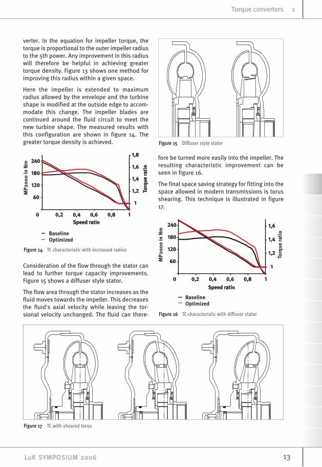
verter. In the equation for impeller torque, thetorque is proportional to the outer impeller radiusto the 5th power. Any improvement in this radiuswill therefore be helpful in achieving greatertorque density. Figure 13 shows one method forimproving this radius within a given space.
Here the impeller is extended to maximumradius allowed by the envelope and the turbineshape is modified at the outside edge to accom-modate this change. The impeller blades arecontinued around the fluid circuit to meet thenew turbine shape. The measured results withthis configuration are shown in figure 14. Thegreater torque density is achieved.
Consideration of the flow through the stator canlead to further torque capacity improvements.Figure 15 shows a diffuser style stator.
The flow area through the stator increases as thefluid moves towards the impeller. This decreasesthe fluid's axial velocity while leaving the tor-sional velocity unchanged. The fluid can there-
fore be turned more easily into the impeller. Theresulting characteristic improvement can beseen in figure 16.
The final space saving strategy for fitting into thespace allowed in modern transmissions is torusshearing. This technique is illustrated in figure17.
1133LLuuKK SSYYMMPPOOSSIIUUMM 22000066
TToorrqquuee ccoonnvveerrtteerrss 11
Figure 14 TC characteristic with increased radius
Figure 16 TC characteristic with diffusor stator
Figure 17 TC with sheared torus
Figure 15 Diffuser style stator

Here a semi-squashed torus is sheared along thecenterline in order to make space for either anarc spring damper at the outside diameter or astraight spring damper near the inside diameter.The outer tip of the torus is shifted by thedesired amount, the inside edge does not moveand the points in between are sheared over to aline connecting the inner and outer points. Thisstrategy maintains the torus flow to maximum
extent possible and therefore the characteristicsare not degraded as shown in figure 18.
The combination of these strategies can be cho-sen based on the application, enabling LuK tomeet the rising demand for torque capacity whiledramatically shrinking the required space andimproving fuel economy and NVH behavior.
Damper and ClutchInnovation Overall greater driveline efficiency is beingachieved by increasing the ratio spread andincreasing the number of gear ratios of planetaryautomatic transmissions. Increasing the usageof the TCC presents an opportunity for evengreater benefit. To accomplish this, the TCC mustbe capable of a greater number of engage-ments at higher energies than in the past. Ofcourse, NVH issues from torsional drivetrainvibrations often limit lock-up speeds, so extraattention must also be paid to the damperdesign.
LuK has been using asystem or holisticapproach to drivelinedamper tuning forover twenty years.This approach haslead to the develop-ment of various damp-er concepts such asthe Dual Mass Fly-wheel (DMF) and theTurbine Damper. Thisexperience and thetools developed overthis period of timeallow LuK an un-paral-leled ability to tailordampers to meet thechallenges of theever-changing auto-motive market. Thecurrent automotivemarket is seeing theintroduction of manytypes of transmis-sions. These include 6and 7 speed planetary
1144 LLuuKK SSYYMMPPOOSSIIUUMM 22000066
11 TToorrqquuee ccoonnvveerrtteerrss
Figure 18 TC charactersitic
Figure 19 Possible Damper positions for a traditional planetary automatic transmission
automatic transmissions, belt, chain, andtoroidal CVT's, parallel and series hybrids withnumerous start/stop systems, and double clutchpowershift transmissions. Recent engine trendsalso demand our attention with the ever-increas-ing popularity of diesel engines and the resur-gence of engines with cylinder deactivationcapabilities.
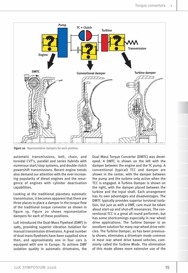
Looking at the traditional planetary automatictransmission, it becomes apparent that there arethree places to place a damper in the torque flowof the traditional torque converter as shown infigure 19. Figure 20 shows representativedampers for each of these positions.
LuK introduced the Dual-Mass Flywheel (DMF) in1985, providing superior vibration isolation formanual transmission drivetrains. A great numberof dual-mass flywheels have been supplied sincethen, and approximately one in four cars isequipped with one in Europe. To achieve DMFisolation quality in automatic drivetrains, the
Dual Mass Torque Converter (DMTC) was devel-oped. A DMTC is shown on the left with thedamper between the engine and the TC pump. Aconventional (typical) TCC and damper areshown in the center, with the damper betweenthe pump and the turbine only active when theTCC is engaged. A Turbine Damper is shown onthe right, with the damper placed between theturbine and the input shaft. Each arrangementhas its own advantages and disadvantages. TheDMTC typically provides superior torsional isola-tion, but just as with a DMF, care must be takenabout start-up and shut-off resonances. The con-ventional TCC is a great all round performer, buthas some shortcomings especially in rear wheeldrive applications. The Turbine Damper is anexcellent solution for many rear wheel drive vehi-cles. The Turbine Damper, as has been previous-ly shown, eliminates a drivetrain mode commonin most rear wheel drive based vehicles, com-monly called the Turbine Mode. The eliminationof this mode allows more extensive use of the
1155LLuuKK SSYYMMPPOOSSIIUUMM 22000066
TToorrqquuee ccoonnvveerrtteerrss 11
Figure 20 Representative dampers for each position.
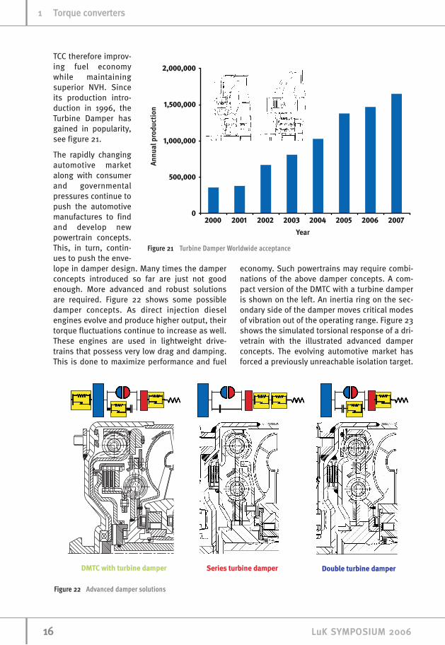
TCC therefore improv-ing fuel economywhile maintainingsuperior NVH. Sinceits production intro-duction in 1996, theTurbine Damper hasgained in popularity,see figure 21.
The rapidly changingautomotive marketalong with consumerand governmentalpressures continue topush the automotivemanufactures to findand develop newpowertrain concepts.This, in turn, contin-ues to push the enve-lope in damper design. Many times the damperconcepts introduced so far are just not goodenough. More advanced and robust solutionsare required. Figure 22 shows some possibledamper concepts. As direct injection dieselengines evolve and produce higher output, theirtorque fluctuations continue to increase as well.These engines are used in lightweight drive-trains that possess very low drag and damping.This is done to maximize performance and fuel
economy. Such powertrains may require combi-nations of the above damper concepts. A com-pact version of the DMTC with a turbine damperis shown on the left. An inertia ring on the sec-ondary side of the damper moves critical modesof vibration out of the operating range. Figure 23shows the simulated torsional response of a dri-vetrain with the illustrated advanced damperconcepts. The evolving automotive market hasforced a previously unreachable isolation target.
1166 LLuuKK SSYYMMPPOOSSIIUUMM 22000066
11 TToorrqquuee ccoonnvveerrtteerrss
Figure 21 Turbine Damper Worldwide acceptance
Figure 22 Advanced damper solutions

These advanced damper concepts allow us toprovide damper solutions that do attain thesetargets.
Hybrid vehicles are entering the market, andthere are several hybrid drivetrain layouts. Somecontain torque converters, some dry or wetclutches, while others eliminate the launchdevice completely. All hybrid drivetrains mustdeal with torsional isolation, and in most cases,a damper is required. A damper for a hybrid sys-tem without a launch device is shown in figure24. This damper is installed between the engineand the transmission. The transmission containsan electric motor used to start the engine after ithas been shut off each time the vehicle stops.
The damper must have a sufficiently low springrate to isolate torsional vibrations throughoutthe engine operating range. This low spring ratecan create a problem when the engine starts.The natural frequency of the engine-damper-electric motor system lies at an engine firing fre-quency below idle. This resonance must becrossed every time the engine is started orstopped, which can create noise and durabilityproblems. To avoid this issue, a lockout clutchcan be provided which is engaged during enginestart-up and shut-off. A spring applies thisclutch, and pressurized oil disengages this
clutch when the engine is running. The enginedrives an oil pump through a pump hub similarin design to that of a torque converter.
The Multi-FunctionTorque Converter(MFTC) The MFTC was developed and presented in theLuK Symposium 2002 [3]. Development on thisconcept has continued, since it addresses chal-lenges presented by both SUVs and dieselengines. The demand for increased fuel economyfrom SUVs requires lower lock-up speeds and lessidle losses. Torque converters used with dieselstypically need their TC characteristics tailored to
1177LLuuKK SSYYMMPPOOSSIIUUMM 22000066
TToorrqquuee ccoonnvveerrtteerrss 11
Figure 24 Hybrid damper with lockout feature to eliminatestart-stop resonance
Figure 23 Drivetrain response versus target for advanceddamper concepts
carry the higher torque from the diesel engine,and special attention needs to be paid to the TCCdamper to deal with the higher torque fluctua-tions from a diesel. In the MFTC, when the TCC islocked, this concept provides an inertia distribu-tion similar to a dual-mass flywheel as shown infigure 25. It also has a clutch between the engineand the impeller, which can be disconnected atstoplights to save fuel at idle.
A three-pass MFTC designed for a gasoline en-gine SUV is shown in figure 26. This design usesa multi-plate TCC with a closed piston, a conven-tional arc spring damper, and an additionalimpeller clutch. The outer pressure channelbetween the pump hub and the stator shaft con-trols the impeller clutch, which provides an idledisconnect function. The inner pressure channelbetween the stator shaft and input shaft isalways kept at high pressure and provides thecharge pressure for the torque converter torus.The channel through the center of the input shaft
provides pressure tolock-up the TCC.
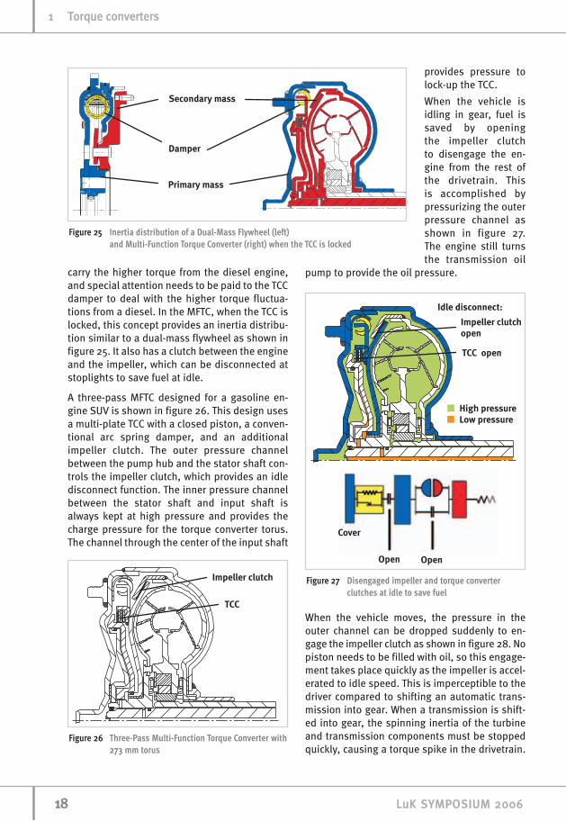
When the vehicle isidling in gear, fuel issaved by opening the impeller clutch to disengage the en-gine from the rest ofthe drivetrain. Thisis accomplished bypressurizing the outerpressure channel asshown in figure 27.The engine still turnsthe transmission oil
pump to provide the oil pressure.
When the vehicle moves, the pressure in theouter channel can be dropped suddenly to en-gage the impeller clutch as shown in figure 28. Nopiston needs to be filled with oil, so this engage-ment takes place quickly as the impeller is accel-erated to idle speed. This is imperceptible to thedriver compared to shifting an automatic trans-mission into gear. When a transmission is shift-ed into gear, the spinning inertia of the turbineand transmission components must be stoppedquickly, causing a torque spike in the drivetrain.
1188 LLuuKK SSYYMMPPOOSSIIUUMM 22000066
11 TToorrqquuee ccoonnvveerrtteerrss
Figure 25 Inertia distribution of a Dual-Mass Flywheel (left) and Multi-Function Torque Converter (right) when the TCC is locked
Figure 27 Disengaged impeller and torque converterclutches at idle to save fuel
Figure 26 Three-Pass Multi-Function Torque Converter with273 mm torus

In the MFTC, the comparatively small inertia ofthe impeller is accelerated against the TC fluidcircuit, resulting in a smooth torque increase.
When torque converter clutch lock-up is com-manded, the channel through the input shaft ispressurized as shown in figure 29. The resultinginertia arrangement is similar to a dual-mass fly-wheel. An advantage of this three-pass arrange-ment is that the impeller clutch retains its torqueat all times, so that the driver's perception of TCCengagements is not different from a typical lock-up torque converter.
The dual-mass inertia arrangement providessuperior vibration iso-lation. Figure 30shows a simulation ofthe torsional vibra-tions of the differen-tial in a large SUV withthe MFTC and the production TCC. The MFTC allows the lug-ging limit to be low-ered by 200 rpm.Measurements takenin the vehicle showthis improved isola-tion in figure 31.
1199LLuuKK SSYYMMPPOOSSIIUUMM 22000066
TToorrqquuee ccoonnvveerrtteerrss 11
Figure 28 Engaged impeller clutch provides conventionaltorque converter operation
Figure 29 Pressurizing the closed piston engages the torque converter clutch
Figure 30 Simulation of torsional vibration isolation improvement with MFTC
Figure 31 Measurement of torsional vibration isolation improvement with MFTC

The impeller clutch can be slipped or engagedduring launch, providing in effect a variabletorque converter characteristic. This can be ben-eficial in reducing the acceleration lag present inturbocharged diesels. Figure 32 shows the out-put torque of a turbo diesel engine at wide-openthrottle. Each point in the top curve shows theengine output torque recorded at constantengine speeds after the turbocharger has hadtime to get up to speed. The bottom curve showsthe torque output of the engine when the throt-tle is first opened, and the turbocharger has nothad time to get up to speed. The difference aris-es because it takes time for the exhaust to accel-erate the turbocharger to produce boost. Whenthe engine runs at higher speeds, there is moreexhaust flow to spin the turbocharger. Therefore,it takes less time for the engine output toincrease from the bottom curve to the top curveas engine speed increases.
If the engine was relieved of some of its load atthe beginning of the launch it will reach high
speeds sooner, which will then accelerate theturbocharger quicker, and the engine will buildup potential faster. An example of this situationin a light truck is shown in figure 33. At thebeginning of the launch, all of the engine'storque is used to accelerate its own inertia so itgets up to a higher speed quickly. When it beginsto produce higher torque the MFTC impeller clutch is closed, which launches the vehicle. Thevehicle begins moving 0.2 seconds later usingthis strategy. However, the rapid increasedtorque output from the engine more than makesup for this difference and the vehicle reaches30 km/h 0.2 seconds faster.
Friction Launch and the MechanicalTorque Converter An extension of the trend towards higher per-formance dampers and increased TCC usageleads to the natural evolution of the wet clutch asa launch device. Devices of this nature complete-ly eliminate the need for a hydrodynamic torqueconverter and allow for reductions in mass, iner-tia, and installation space. As a result, sufficientpackaging space for a sophisticated damper sys-tem that will allow the clutch to remain lockedduring all driving conditions results, thereforeoffering higher system efficiencies than can beachieved with conventional hydrodynamictorque converters.
Two approaches to wet friction launch clutchesexist: 1) the device can be part of a clean sheetof paper design and can be integrated into thetransmission assembly itself, or 2) the devicecan be a plug in direct replacement for thetorque converter of an existing transmission. Thecore understanding required to arrive at success-ful concepts for each of these approaches is fun-damentally the same. Therefore, it is the latter ofthese two approaches that LuK is focusing uponas this design direction leads to the additionalbenefits of near drop-in compatibility and theelimination of costly transmission design effortsand large production capital investments. How-ever, this design direction brings with it the chal-lenges of creating a system that is compatiblewith the limitations of an existing transmission
2200 LLuuKK SSYYMMPPOOSSIIUUMM 22000066
11 TToorrqquuee ccoonnvveerrtteerrss
Figure 32 Engine output torque variation due to turbocharger lag
Figure 33 Simulation of improved acceleration from slipping impeller clutch

design, most notably with respect to providingsufficient cooling oil to the launch clutch itselfand, in some cases, offering comparable vehiclelaunch performance and feel.
Figure 34 depicts the basic launch device con-cept. The wet launch clutch and damper systemare contained within a housing much like that ofa conventional torque converter. All interfaces ofthis system are the same as the base hydrody-namic design that it replaces, meaning there areno required changes to the pilot, lugs, pumphub, and transmission pump drive. Additionally,the stator shaft of the transmission is requiredfor the function of the device so it does not needto be modified or removed.
The system is configured such that torque pass-es through the housing, into the torsionaldamper, through the wet launch clutch, and theninto the transmission input shaft. This arrange-ment of springs and inertias results in a very
favorable configuration with respect to NVH iso-lation. In fact, this configuration is not unlike thestandard dual mass flywheel concept. The clutchis actuated via a sealed hydraulic piston which isconnected to the existing transmission TCC applychannel. There is no need for a charge pressureas with a conventionalTC, and the outlet of the clutchhousing can be left at atmospheric pressure andallowed to drain back to the transmission sump.
The cooling requirements of a wet launch clutchwould typically demand an oil flow rate of 20 to30 l/min, depending upon the application.Unfortunately, this flow rate is not available inmost existing transmissions and would requiresignificant re-design and a larger transmissionpump in order to realize this flow rate. However,the cooling system detailed in figures 35 and 36is a simple approach, which circumvents thisproblem and enables the clutch to be cooledadequately without changes to the base trans-mission's hydraulics.
The system consists of two independent coolingcircuits, one which is actively linked to the applypressure of the clutch, the other which is pas-sively connected to the output of the clutch. Thefirst system (Figure 35) consists of a flow controlorifice in the sealed clutch apply piston and afixed scoop pipe. Cold, high-pressure oil is bledoff through the flow control orifice at a rate ofapproximately 5 l/min. This cold oil passesthrough the clutch, extracting heat along theway. The scoop pipe, which is splined to the sta-tor shaft and thereby fixed rotationally, returnsthis 5 l/min of now hot oil to the sump. This pipe
2211LLuuKK SSYYMMPPOOSSIIUUMM 22000066
TToorrqquuee ccoonnvveerrtteerrss 11
Figure 34 Friction Launch Clutch
Figure 35 Cooling Circuit 1

also serves to control the fixed volume of oilwithin the clutch housing, meaning the clutchpack is not submerged.
The second cooling circuit (Figure 36) consists ofone additional scoop pipe, this time attached tothe output of the clutch/input of the transmis-sion. This pipe serves to recirculate oil throughthe clutch at a high volume flow rate, therebyproviding the additional cooling that the clutchrequires during a launch event. This pipe, whichdelivers up 25 l/min, will only pump when thereis slip across the clutch. Once the launch event iscomplete and the input and output speeds of theclutch are synchronized, the kinetic energy ofthe fluid relative to the scoop pipe is zero andthe system no longer pumps. The combination ofthese cooling circuits as well as not having aclutch pack that is submerged in fluid, by virtueof the first scoop pipe, means that the systemoperates with the minimum of drag or pumpinglosses. Additionally, this system may be tuned sothat idle disconnect functionality can be realized.
Systems of this nature are particularly well suit-ed for front wheel drive applications wherespace is at a premium, but also have applicationin rear wheel drive platforms. As the launch ener-gy that the clutch must be capable of dissipatingis a function of the vehicle mass, overall gearratio of the transmission, engagement time, andengine performance it is likely that modern 6-speed applications are the target for this system.
However, should an application exist that doesnot have the required overall launch ratio or thatis particularly heavy or underpowered, the com-
bination of the previously discussed concept anda simple planetary gearset offers an attractivealternative when investigating friction launchclutch concepts. Alternately, the concept cantransform an existing 4-speed transmission intoa 6-speed whilst offering improvements in per-formance and fuel economy. The gear ratios ofthe MTC in conjunction with two speeds of thetransmission transform the 4 speed baselinetransmission into a 6-speed. This approach hasthe added benefit of enabling a transmissionmanufacturer to be market ready with 6-speedofferings whilst having none of the financial bur-den of designing and producing a new transmis-sion.
LuK has also completed significant design workfor a concept like this, which is known as theMechanical Torque Converter (MTC). This productsatisfies all of the design objectives of the fric-tion launch clutch in terms of drop-in compatibil-ity, making use of existing transmission andengine interfaces, as well as utilizing the samecooling concept as previously discussed. TheMechanical Torque Converter consists of onelaunch clutch actuated via a sealed piston, onesequential clutch that is used for gear ratiochanges, a planetary gear set and two torsionalisolators for NVH performance that will allowfully locked driving. See figure 37.
Simulations for this device show a reduction in0-60 mph acceleration times of 10% while offer-ing a 7% increase in fuel economy vs. the base-line 4-speed planetary automatic with a hydro-dynamic torque converter.
2222 LLuuKK SSYYMMPPOOSSIIUUMM 22000066
11 TToorrqquuee ccoonnvveerrtteerrss
Figure 36 Cooling Circuit 2
Figure 37 The Mechanical Torque Converter

The device operates in three discrete modes.These modes, shown in Figures 38, 39 and 40,are idle disconnect mode, torque multiplicationmode and fully locked mode. Idle disconnectmode is achieved by having no apply pressurecommanded to the clutches. In this case allclutches are open, no flow is entering the device,and the scoop pipe 1 will partially empty theenclosure and the system will run with a mini-mum of drag torque. However, the transmissionpump is continuously driven via the pump hub,so all functions in the transmission itself willoperate normally. See figure 38.
Vehicle launch is managed by commanding pres-sure to Clutch 1, which will simultaneously initi-ate the launch event and fill the system with oilvia the flow control orifice (figure 39). As such,the clutch will automatically be provided with
cooling oil via the aforementioned scoop pipearrangement. The apply force on Clutch 1 isreacted via a preloaded diaphragm spring, whichserves to ensure that Clutch 2 will not be actuat-ed. In this mode, torque passes from the cover tothe main system damper, and then to the pistonplate, which is flexibly connected to the damperto allow the actuation travel of the piston tooccur. The output of the launch clutch is theinput to the planetary set, in this case the ringgear. The sun gear of the planetary set is ground-ed via a one way clutch to the stator shaft of thetransmission, leaving the planetary carrier as theinput to the transmission with a torque ratio ofapproximately 1.65 times engine torque. Anadditional damper, situated between the plane-tary carrier and the transmission input shaft, isrequired to control an input shaft resonance,which is excited at low engine speeds.
Changes in the gear ratio of the device are real-ized by further increasing pressure to the piston(figure 40). Once the preload of the diaphragmspring is overcome, Clutch 2 will begin toengage. As such, the planetary set will now belocked and the ratio of the system will changefrom that of 1.65:1 to 1:1. This transition is man-aged by simply taking torque off of the one-wayclutch with Clutch 2, an event that is easier to
manage than clutch to clutch shifting. Further-more, the pressure at which this event takesplace can be altered via changes in diaphragmspring preload, resulting in a system that isflexible to the needs of various hydraulic controlcircuits.
2233LLuuKK SSYYMMPPOOSSIIUUMM 22000066
TToorrqquuee ccoonnvveerrtteerrss 11
Figure 38 Idle Disconnect Mode
Figure 39 Torque Multiplication Mode
Figure 40 Fully Locked Mode
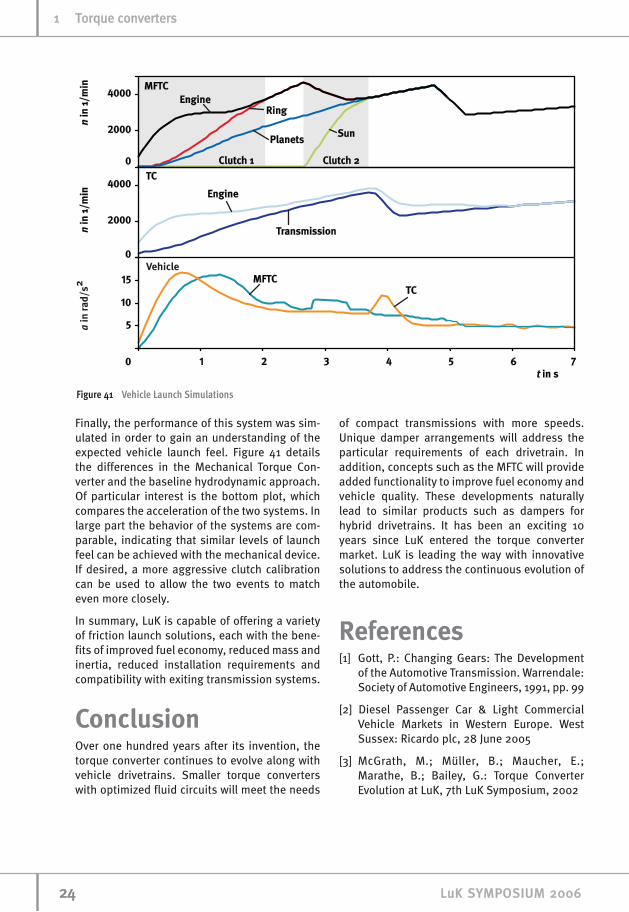
Finally, the performance of this system was sim-ulated in order to gain an understanding of theexpected vehicle launch feel. Figure 41 detailsthe differences in the Mechanical Torque Con-verter and the baseline hydrodynamic approach.Of particular interest is the bottom plot, whichcompares the acceleration of the two systems. Inlarge part the behavior of the systems are com-parable, indicating that similar levels of launchfeel can be achieved with the mechanical device.If desired, a more aggressive clutch calibrationcan be used to allow the two events to matcheven more closely.
In summary, LuK is capable of offering a varietyof friction launch solutions, each with the bene-fits of improved fuel economy, reduced mass andinertia, reduced installation requirements andcompatibility with exiting transmission systems.
ConclusionOver one hundred years after its invention, thetorque converter continues to evolve along withvehicle drivetrains. Smaller torque converterswith optimized fluid circuits will meet the needs
of compact transmissions with more speeds.Unique damper arrangements will address theparticular requirements of each drivetrain. Inaddition, concepts such as the MFTC will provideadded functionality to improve fuel economy andvehicle quality. These developments naturallylead to similar products such as dampers forhybrid drivetrains. It has been an exciting 10years since LuK entered the torque convertermarket. LuK is leading the way with innovativesolutions to address the continuous evolution ofthe automobile.
References[1] Gott, P.: Changing Gears: The Development
of the Automotive Transmission. Warrendale:Society of Automotive Engineers, 1991, pp. 99
[2] Diesel Passenger Car & Light CommercialVehicle Markets in Western Europe. WestSussex: Ricardo plc, 28 June 2005
[3] McGrath, M.; Müller, B.; Maucher, E.;Marathe, B.; Bailey, G.: Torque ConverterEvolution at LuK, 7th LuK Symposium, 2002
2244 LLuuKK SSYYMMPPOOSSIIUUMM 22000066
11 TToorrqquuee ccoonnvveerrtteerrss
Figure 41 Vehicle Launch Simulations

2255LLuuKK SSYYMMPPOOSSIIUUMM 22000066
TToorrqquuee ccoonnvveerrtteerrss 11