Embed Size (px)
Citation preview

*Tornado*
© 1993 Digital Integration*
Manual*
CONTENTS
--------
INTRODUCTION
FINDING YOUR WAY AROUND THE MANUAL
GETTING STARTED
The Main Screen
The Tornado User Interface
Options / Exit buttons
Preferences
Explore
Review
Logs
The Quickstart Users Guide
FLIGHT OPTIONS
Simulator
Training
Combat
What Happens now?
THE MISSION SELECTION SCREEN
The Situation Menu
Other Options Available
THE MISSION PLANNER
Introduction
Section 1 - Using The Mission Planner - Basics
Section 2 - Planning Your Own Missions
Section 3 - Command Level
DEBRIEF
ELEMENTARY FLYING TRAINING
Introduction
Starting The Simulator
Flying The Autopilot And Reading The HUD
Level Turns And Autotrim
The Autothrottle
Stalling
Wing Sweep
Automated Landings
Taking Off
ADVANCED FLYING TRAINING
Introduction
More About Flaps and Slats
Terrain Following (IDS Only)
Maps, The MFD And The Tab Displays
Setting Up Your Own Approach And Landing
Manual Approaches
Landings And Wind Direction
Landing Damaged Aircraft
Emergencies
Spins And Spin Recovery
EXTERNAL VIEWS
WEAPONS CONVERSION
Air To Ground
Weapons Training In The Simulator
Air To Air
AIRCREW NOTES

Cockpit Layout
Avionics Reference
Useful Checklists
REFERENCE
Glossary And Abbreviations
INDEX
INTRODUCTION
------------
Welcome to Tornado - the most comprehensive home computer combat flight
simulator to date. Some of you will already know a good deal about
aircraft and how to fly them, and some of you will be learning these things
for the first time. We have tried hard to cater for both types of user and
to design a product of considerable entertainment and educational value.
Do not be overwhelmed by the huge manual. This is an immense product.
Options range from no-nonsense Quickstart to the multi-aircraft multi
mission campaigns, with exercises in the simulator to prepare you for a
range of combat options unsurpassed by any other product. It is only
possible to begin to appreciate the depth of Tornado after several hours of
intensive use. We expect you to continue to discover new aspects of the
product for months.
Everybody, regardless of experience level, should start by looking at the
separate Technical Supplement. This gives details of how to install the
software, and describes any differences between the version supplied for
your machine and the PC-compatible version upon which this manual is based.
Tornado is a remarkably complete simulation of the Panavia Tornado GR.4
Interdictor / Strike (IDS) and F.3 Air Defence Variant (ADV) aircraft. The
GR.4 will be the upgraded RAF version of the Tornado IDS currently flown by
the RAF, the German, Italian and Saudi Arabian air forces. If you followed
the air war in the Persian Gulf, you will know that this was the aircraft
given the job of keeping the Iraqi air force on the ground by destroying
its airfields. Its purpose in life is to penetrate deep into enemy
territory by flying as low as possible as fast as possible, and deliver
even the dumbest of "dumb" bombs with pinpoint accuracy. It can do all
these things even at night, in thick fog. At low level, in the environment
it was designed for, it is the fastest aircraft in the world.
The Tornado ADV is in service with the RAF and Saudi Arabia. It is a
modified version of the same airframe, equipped to serve as a long-range,
long- endurance two seat interceptor. It has a more powerful radar
optimised for air to-air fighting, and carries medium-range radar-guided
missiles. As the name Air Defence Variant suggests, its intended role is
to defend rather than attack, and it is normally expected to do this by
shooting down enemy bombers. It shares the all-weather capability of the
IDS version, but unlike the IDS it cannot terrain-follow.
This level of performance demands a very sophisticated aircraft. Even with
a crew of two, there is so much to do, and the situation can change so fast
that most of the time the aircraft is flown by an extremely smart
autopilot. You are about to step into the shoes of two very hard-working
aircrew. But even if this is the first flight simulator you have ever
bought, do not despair. You do not have to do it all at once, and we
provide flight training from absolute beginner level if you need it.
Simulating such a complex aircraft was not easy. It involved a phenomenal
amount of research and design but the degree of authenticity achieved would

not have been possible without the assistance of the Royal Air Force and
British Aerospace. We have done everything we can to provide a detailed
and accurate simulation of the aircraft's systems and flying qualities,
with the invaluable help of many RAF Tornado aircrew. We have also
provided a level of visual realism, density and detail which breaks new
ground for a home computer simulation, but even this is only half the
story.
Precise automatic navigation demands precise and detailed flight planning,
and our mission planning system is in many ways far in advance of the one
the RAF uses at present. This is no reflection upon the people and
organisations who developed the system in use - we have the advantage of
nearly ten years of explosive technological progress since that system was
designed.
Within the last few months of Tornado's development, the UK Ministry of
Defence has issued a development contract for a new mission planning
system, to be used for the Harrier GR.7 and potentially the Tornado GR.4.
It is called AMPA (Advanced Mission Planning Aid), due to be in service by
early 1995, and the published description (in Flight International, 20
January 1993) sounds eerily familiar to those of us who specified and
developed Tornados mission planning system. There is no question of one
being a copy of the other - we simply came to very similar conclusions
about what is possible and desirable to do with the available computer
power. But you don`t have to wait until 1995.
We never intended or presumed that this project would attract serious
attention from the people who get to fly the real thing or from the
aerospace Industry, so we were highly gratified when it did. This same
product is now under consideration for professional groundbased training
applications and we are delighted that our efforts are being recognised
outside the entertainment market.
Unlike any of our previous simulations, Tornado is designed to be the first
of many new leading-edge products. We haven't succeeded in putting in
everything that we wanted to no shortage of ideas - just time. These vast
projects involve an unbelievable investment in man power and equipment and
sooner or (usually) later, we have to get the product published in order to
fund the next one. But we do what we enjoy most and we hope it shows,
Thank you for purchasing Tornado - we hope you enjoy it.
The Tornado team
FINDING YOUR WAY AROUND THE MANUAL
----------------------------------
All users should check their Technical Supplement to find out how to
install and start this software.
This chapter covers two main topics: one is the "Front-end" of the program
which among many other things lets you create logs, select missions and
plan them; the other is the aircraft, how to fly it" how the weapons work
and how to use them.
Chapters about the "Front-end"
Chapters 2 to 6 are the ones which describe the "Front end" Everyone needs
to read them, and most of them are short chapters. The chapter describing
the Mission Planner is the longest in the manual, but you only need to read

the first third of it to start with.
Chapter 2 - Getting Started
This describes what you see on the opening screen and how to use it. It
tells you how to start an automatic demonstration, or use the Quickstart
option to leap into combat at a single bound. It also describes how to
configure the software for your machine, set up selectable options, create
Pilot logs and use the Explore and Review modes, which are good
entertainment in themselves
Chapter 3 - Flight Options
This chapter covers the screen you reach by clicking on the large "Flight
icon on the first screen. There are three basic flight modes: Simulator,
Training and Combat; and there are four different varieties of the Combat
Option: Mission Campaign, Command and Two-Player. All the options are
briefly described
Chapter 4 - Mission Selection Screen
This is where you make your choice about what you are going to do within
the Flight or Combat option you selected, and (for the Combat options),
which of the three possible War Zones you are going to fly over.
Chapter 5 - Mission Planner
This is a monster of a chapter because the Mission planner is a very
powerful and sophisticated piece of software. The chapter is divided into
three self contained sections, and the user who just wants to fly preset
missions for the moment can get all that is required from the first of
these.
Chapter 6 - Debriefing
This brief chapter covers the report you see at the end of each flight and
what to do about it if you don't like it.
Chapters about tHe Aircraft and Weapons
These are mainly long chapters covering many topics - if you are new to the
subject there is a lot to learn. Experienced pilots can do a good deal of
skipping. and try to pick up what they need by using the Aircrew Notes in
conjunction with the Index.
Chapter 7 - Elementary Flying Training
This chapter is mainly for the benefit of users who know nothing about
aircraft or flying, including those who have never had to worry about
stalling or overspeeding before. If the aircraft refuses to fly or keeps
shaking itself to pieces around you and you cannot work out what is going
on, grit your teeth swallow your pride and start here. This chapter also
covers automatic landings and taking off
Chapter 8 - Advanced Flying Training
Large parts of this chapter build on the previous one to take a novice up
to a level where he or she can manoeuvre the aircraft freely, set up an
approach and land with a minimum of automatic help. Some of the very
powerful navigation systems and avionics of the Tornado are also described

and the chapter concludes with a section on emergencies, including the spin
recovery drill
Chapter 9 - External Views
This very short chapter describes the rich and flexible optionsfor out of
aircraft views of yourself and others.
Chapter 10 - Weapons Conversion
This chapter should be required reading for everyone, though real Tornado
pilots will be able to skim through it. They will find a few omissions and
simplifications of the systems they know most other users will be faced
with concepts and weapons they may never even have heard of before. You
will never be truly effective until you can use all the possible weapons in
all the possible modes, and you will not be able to do that unless you know
this material, one way or another.
Chapter 11 - Aircrew Notes
This is a summary description of the aircraft instruments and avionics. A
very experienced user may be able to get most of what he or she needs to
know from this chapter in conjunction with the Control Summary card, using
the Index to find detailed descriptions where more explanation is wanted.
Once you know roughly what is available, you can use this chapter for quick
reference
Chapter 12 - Reference
This gives drawings and basic data on aircraft, vehicles and weapons
appearing in Tornado. Know your enemy - and your allies. We should add
the Disclaimer that we are not trying to re-fight the Cold War; we chose
CIS equipment for the "orange" forces because most of these systems
correspond neatly, one to one, with "blue`s" Western equipment. As far as
we are aware all the CIS equipment which features in Tornado is being
actively marketed to the world at large, so "orange" could be almost
anybody. Just add your favourite dictator and stir.
GETTING STARTED
---------------
The Main Screen
All users should consult the separate Technical Supplement for details of
how to install and run Tornado on their particular type of computer. If
you find differences between what is described in this manual and what
appears on your screen, check with the Technical Supplement. Once you have
started the program and the title sequence has finished, you should find
yourself looking at the Main Screen the "Front End" of Tornado. The
overall structure of the program is shown opposite in diagram 2 1.
The Flight Icon
The Main Screen is dominated by the large triangular icon in the centre
labelled "Flight" Do not do this straight away, but if you place the mouse
pointer over this icon and click the left mouse button it will start you on
the normal path to the aircraft, through further stages of selection and
mission planning. The stages in this path are explained in two short
chapters; "Flight Options" and "The Mission Selection Screen"; and one very
long chapter on the Mission Planner
Below the Flight icon are two smaller rectangular icons labelled "Demo" and
"Quickstart".
The Demo Icon
Clicking on this icon changes it into a panel of separate buttons, each
labeled to describe a different kind of demonstration display. If you want
a demonstration of Tornado, place the mouse pointer over one of these
buttons and click the left mouse button. After a pause for loading, the
demonstration will start. When you have seen enough, hold down the Ctrl
key and press Q to return to this screen
The Quickstart Icon
The Quickstart options will put you straight into the cockpit, in flight
and in action. Though there is a vast depth of gameplay available in
Tornado through the Mission Planning functions, not everyone will want to
go through the whole process every time - and however keen you are it will
take time to learn how to use the Mission Planner. Quickstart lets you
bypass the planning process and the need to take off or land.
Just like the Demo icon, the Quickstart icon changes into a panel of
buttons when you click on it. Four choices are offered, easy and hard
variations on air to air and air to-ground combat. Click on the one you
want, and you will find yourself in the cockpit, in the thick of the
action. The Air-to-ground options put you in the cockpit of an IDS
(Interdictor/Strike) Tornado, with a payload of bombs, while the air to-air
options give you a Tornado ADV (Air Defence Variant), the interceptor
version, armed with air to air missiles
Before you try out Quickstart, read the section at the end of this chapter
which attempts to put over the absolute minimum you need to know to avoid
instant frustration. The Easy Quickstart options make you immune to the
enemys weapons and most of the consequences of hitting the ground, but it
is still entirely possible to destroy or cripple the aircraft if you do not
know roughly why and how to use the wing sweep system. The weapons systems
are also realistic, and do not have the magical properties you may have
come to expect If you want hits you are going to have to work for them
The Tornado User Interface
Most computer users should be able to handle our point-and-click system at
a glance, but we do use a few novel conventions we have invented for our
own purposes. Here we will try to explain how the system works from
absolute basics upwards. Experienced users should bear with us - some of
this will be new to them as well.
Pointing and Clicking
The front-end of the Tornado system (that is, everything outside the
cockpit of the aircraft), is designed to be controlled exclusively by your
mouse. The only time you will need to use the keyboard is to type in names
when creating Pilot logs. To activate a function, you just move the mouse
over your desk to place the mouse pointer symbol on the screen (a small
upright cross) over an icon or a button (both are defined below), and click
the left button on the mouse. The right mouse button is only used to move
about and change zoom levels on the Mission Planner Map.
Icons and Buttons

Icons are picture-symbols with borders around them, like the Flight, Demo
and Quickstart symbols on the Main Screen. Buttons are small outlined
panels with text in them, like the rectangles marked "Options " and "Exit"
in the lower right corner of the screen.
Sometimes clicking on an icon or a button will cause an immediate action
sometimes the icon will subdivide into smaller icons (or buttons) to offer
you more choices, and sometimes it will call up a window (see below), which
may display text and/or contain still more buttons.
Many buttons will change colour when you click on them, to indicate that
the function or option they control is selected (switched on). Sometimes
you will see a row or column of buttons, only one of which may be selected
at a time - these are often called "radio buttons". Most of the time the
text on the buttons should tell you what they mean and what they do. If it
is not oblious, check with this manual. If a button disappears after you
make a selection, it is because that button`s function is now irrelelant or
inappropriate.
There are two special types of button which are peculiar to Tornado; the
Cycle button and the Figure button
Cycle buttons
A Cycle button is a space-saling substitute for a bank of "radio buttons".
It is a small square button with a circle/arrow symbol in it, always placed
to the left of a short text panel describing an option or a state.
Clicking on the Cycle button changes the text, selecting a different option
or state. Up to four different options may be selectable by clicking
repeatedly on a Cycle button.
The first Cycle button you are likely to encounter is the one on the
Preferences screen (see below)
Figure buttons
Figure buttons are provided where you need precise control over a figure
(usually a time, a speed or an altitude). The digits of the figure,
sometimes grouped together, will be outlined to mark them as buttons. To
change the figure, click on the button showing the digit(s) you are
interested in. This will cause two further buttons to appear, marked with
arrows, one above and one below the digit(s). Click on the arrow buttons
to change the figure up and down by one; click and hold down the mouse
button for rapid change.
When you change a digit up past 9 or down past 0 the next digit up will
also change up or down, even though it is not selected. You can instantly
select another digit to change by clicking on it, or dismiss the arrow
buttons by clicking again on the selected digit itself.
Windows
These are independent superimposed panels (like small inset screens within
the larger screen) showing text, or groups of related buttons, or both.
Each has a specific purpose. You will find most of them in the Mission
Planner, though they do occur elsewhere. All the windows you will see in
Tornado have a title Bar, which should usually explain what they are for.
Any window may be moved (dragged) anywhere on the screen by clicking in the
Title Bar and holding down the mouse button. Moving the mouse will then

drag an outline of the window across the screen. When it is in the place
where you want it, release the mouse button and the window will be redrawn
in its new position.
Most windows also have a Close box. This is found at the left-hand end of
the Title Bar. Clicking in the Close box will close the window, causing it
to disappear. Some windows do not have a Close box, either because there
is no reason for closing them or because they are telling you something it
would be unwise to ignore, like the Problems window in the Mission Planner
which tells you when your flightplan is risky or outright suicidal.
Windows can lie on top of one another, partly or totally overlapping. If
the one you want is behind another, just click in the Title Bar of the
window you are interested in to put it in front. On the PC version at
least, you can choose whether the windows themselves are opaque or
semi-transparent (see the preferences option below).
OPTIONS.../EXIT BUTTONS
In the bottom right corner of all screens (except when flying, exploring or
going through a recognition review) is a pair of buttons, marked "Exit" and
"Options" If you click on "Exit" you will go back to the previous screen,
or if you are on the main screen (the first screen), you will be asked if
you want to quit the program. Whenever this button is shown, the option is
always available, and you can use it without incurring penalties.
The upper of the two buttons, marked "Options" works in a different way. If
you click on this and hold down the mouse button, it will expand into a menu
showing the following options;
System Allows you to quit the program immediately
Preferences For fine-tuning the program for your equipment
Explore Lets you explore any map as a disembodied eye
Review Shows all military aircraft and fighting vehicles
Log For creating, selecting or reviewing Pilot Logs
Cancel Does nothing - the safe option!
When the menu first appears, the "Cancel" item is under the mouse pointer.
Keep holding the mouse button down and move the pointer up and down over
the menu. You will see that each item is highlighted in turn as the
pointer moves over it. Move the pointer back down over "Cancel" and
release the button. The menu collapses back into the "Options" button, and
nothing else happens - which is just what the "Cancel" option is supposed
to do nothing.
All the items in this menu work the same way; click on "Options..." and
hold down the button, move the pointer till the item you want is
highlighted, and then release the button.
The "System" and "Cancel" options do not really need explaining. The other
options are explained in the following sections. Several of these call up
screens which themselves contain the "Options..." and "Exit" buttons.
Clicking on "Exit" from any of these will return you to the previous
screen.
PREFERENCES
This screen allows you to preset various optional features of the
simulation, to select sound hardware where appropriate, and to turn the
title music on and off. Many of these switches are provided to allow you

to cut down on detail and improve speed, if you think that your computer is
running too slowly - it takes a fast machine to run Tornado at a high frame
rate if all the options are turned on.
The switches on this screen divide into three groups. One of these groups
almost exactly duplicates the switches avaIlable in flight using the
Kneepad (Look Down) View, and is mainly concerned with setting up the
simulation environment. On the Kneepad, you switch options by pressing the
number keys on the top row of the keyboard, here you point and click.
Simulation Preferences
Visual Range
In your outside views, nothing will be drawn beyond the selected Visual
Range, which is given in miles. Click on a figure to select it.
More <--- DETAIL ---> Less
25 20 15 10 5
Slower <--- SPEED ---> Faster
Ground
This switch will turn on or off most of the groups of trees and the field
patterns we have provided to give a true sensation of speed and depth in
low-level flight
More <--- DETAIL ---> Less
Textured Plain
Slower <--- SPEED ---> Faster
Hills
We chose not to use the currently-fashionable Gouraud shading effect to
represent undulating landscape. This looks very good in the distance, but
makes it nearly impossible to judge your height above ground by eye because
close to the aircraft the shading degenerates into an unstable shifting
mass of colour. Instead, when this switch is set to "Textured" the faces
making up the hills will subdivide into smaller counter-shaded faces as you
approach them. This may not look as flashy, but it is stable, and it lets
you judge depth and distance well enough to terrain follow manually - if
you are up to it.
More <--- DETAIL ---> Less
Textured Plain
Slower <--- SPEED ---> Faster
Horizon
This allows you to choose between a smoothly graduated horizon (Faded) and
a plain blue sky ("Plain"). Click on the option of your choice.
More <--- DETAIL ---> Less
Faded Plain
Slower <--- SPEED ---> Faster
Sky
This switch allows you to turn the thin layers of individual clouds on
(textured) or off (Plain). The overcast effect (a thick solid cloud layer)
will not be affected
More <--- DETAIL ---> Less
Textured Plain
Slower <--- SPEED ---> Faster
Ironwork
This peculiarly-named switch controls whether you will see the cockpit
canopy framework and the brackets supporting the Head-up Display. Turning
this switch off will speed up the frame rate considerably on slower
computers.
More <--- DETAIL ---> Less
On Off
Slower <--- SPEED ---> Faster
Control Device
This switch allows you to select which of a range of possible devices you
will use to fly the aircraft. Click on the Cycle button repeatedly to see
the range of options available, then leave the desired option showing the
options available will differ from one computer to another; those described
here apply to the PC version, but users of ALL machines should check their
Technical Supplement for changes:
Keyboard 1 Pitch and roll control by numeric keypad / cursor keys. Control
input increases the longer you hold the key down, but returns to neutral
when the key is released.
Keyboard 2 Pitch and roll control by numeric keypad/cursor keys. Control
input increases the longer you hold the key down. When you release the key
the control input stays at its last level - if you want to stop rolling or
pitching you`ve got to make an opposite input, or hit the Autotrim key (5 -
numeric pad).
Joystick 1 Pitch and roll control by single analogue joystick in game port
1.
Joystick 2 Pitch and roll control by analogue joystick in port 1, throttle
and rudder control by second analogue joystick in port 2.
Recalibrate Joystick
This button is used to ensure that the computer recognises the centre
position of your joystick(s). Let the joystick spring to its centre
position and then click on this button. If you find that the aircraft is
developing a persistent roll or a tendency to climb or dive, it is almost
certainly because your joystick centre position is drifting over time. You
can recalibrate in flight by centring the stick and hitting the Y key.
Sound and Music Preferences
Sound hardware varies a lot between computers - even between PCs. Check
the Technical Supplement for your machine to sort out the specific details
There are two options which will always be present on this page, however:
Effects

There are three "radio buttons" for this option "Off" switches off all
sound effects; "On-Eng" gives you all sound effects except the noise of
your own engines, and "On+Eng" gives you all sound effects including your
own engine noise.
Music
This switches the front-end incidental music on or off
Miscellaneous Preferences
This is a catch-all group with a lot of unrelated options in it.
Review Stills
The digitised pictures of aircraft and vehicles available in Review mode
(see below) are high quaiity images, but they do take up a lot of disc
space. If you have installed a working copy of Tornado on a hard disc and
you want to reclaim the disc-space used by these images you can click on
the "Delete" button here to remove them from the installed copy. When you
have deleted these images, you can only get them back by re-installing the
program.
Panel lighting
This switch allows you to select red or green cockpit lighting for flying
at night. Real Tornados may be fitted with either option, and we thought
that both looked good. The brightness of the cockpit lighting is set
according to how dark it is outside, and you can also adjust the HUD
contrast to avoid dazzling yourself on a dark night (see the Cockpit
Controls section on the Control Summary card). We recommend dimming the
room lights when flying at night.
Curve Segments
On the Mission Planner map, curves are drawn in flightplans wherever you
change course. When there are a lot of curves (and a lot of flightplans)
to draw, producing smooth curves can take up a surprising amount of
computer time - a smooth curve has to be drawn as a lot of short straight
lines. The "radio buttons" for this option allow you to choose how many
lines will be drawn to represent a curve.
Smoother <--- CURVE ---> Coarser
32 16 8 4 2
Slower <--- SPEED ---> Faster
Contour Interval
Contours are shown on the Mission Planner map to give you an idea of the
height and shape of hills. Like curve-drawing, this can consume a lot of
processing power and slow your machine down noticeably. These radio
buttons, let you select the interval between contours in feet. The lowest
contour drawn is always the 250 line.
More <--- CONTOURS ---> Fewer
250 500 1000
Slower <--- SPEED ---> Faster
Windows
This option may not be available for all versions. When it is, you have a
choice between see through windows and solid ones. On the Mission PIanner
map, transparent windows let you see through the window to the map, but
solid windows are drawn faster.
Transparent <--- WINDOWS ---> Solid
Slower <--- SPEED ---> Faster
EXPLORE
Explore Mode is a highly useful feature which is also good fun. When you
select the Explore option the screen changes to show you a full screen
window onto a map of the current Flying Area. When in Simulator or
Training modes, this will always be the Training Area, but when you select
Combat, the Mission Selection Screen provides the facility to choose any
one of three different War Zones. If you move the mouse pointer against
any screen edge, the screen window will be dragged across the map in the
corresponding direction. Click on the LEFT mouse button to zoom in, click
RIGHT to zoom out. Note that when you do this the point under the mouse
pointer will be moved to the centre of the screen.
Click on some recognisable feature (a city or an airfield, say), and then
hit the Spacabar or the Enter key. You will find that your view is now
that of a disembodied eye floating sixteen feet above ground level at the
spot you clicked upon. Using the keyboard, the mouse or joystick(s) you
can now move at will in three dimensions at high speed, or hover on the
spot. You can go almost anywhere and see anything except the positions of
aircraft and vehicles.
At any time you can flip back to the map screen, click on another point as
far away as you like, and then return to the three-dimensional world at
that spot. You can use this system for entertainment, for familiarising
yourself with the landmarks, or within the Mission Planner to find out how
your target will appear as you approach it. The military term generally
used for this is Mission Rehearsal, and armed forces everywhere are trying
to acquire this sort of facility, for obvious reasons.
You will find a complete list of the Explore Mode controls in the separate
Control Summary. To leave Explore mode, hold down the Ctrl key and hit Q
REVIEW
The Review feature allows you to see digitised photographs of the aircraft
and military lehicles you will encounter, and compare them with the 3D
models representing them in Tornado. There are two main purposes for this:
on the one hand it helps you develop the ability to recognise friendly and
enemy hardware. On the other, it shows off the models, of which we are
very proud. The guiding principle in constructing these models has been
that if you can recognise the real thing you should be able to recognise
the model, and vice versa.
When you enter Review mode, you will see the screen split between an upper
display area where the models are shown and a lower area showing the
aircraft or vehicle name with a control panel. The Icons on the panel are
explained in diagram 2 2. Clicking on the film strip icon displays a full
screen digitised picture. To return to the model display just click on
either of the mouse buttons. Keystrokes can be substituted for some of the
mouse commands (see the Control Summary) If you want more detailed
information on a particular aircraft or vehicle, look it up in the
Reference section of this manual. To leave Review mode hold down the Ctrl
key and hit Q, or click on the Eject button.
LOGS
The Pilot Log system is a schizophrenic`s paradise: it allows you to be up
to 20 different people. Any time you`re flying a Tornado, you are doing so
under one of these 20 possible identities, with a name, a nominal RAF rank
and a record of flying hours and experience. Most of these identities you
create for yourself by choosing a name and typing in, but one is special -
the default log. This log is supplied with the software, and is
automatically selected every time you start Tornado. The log is in the
name of Group Captain deFault and you can use it just like any other log,
but it has several interesting features.
One of Group Captain deFault`s good points is his rank equal to the highest
available in Tornado. Using this log identity you are automatically
qualified to play the Command wargame, which is only open to pilots who
have earned the notional rank of Wing Commander or above (see the table of
RAF ranks below). You can earn promotion for a pilot whose log you created
yourself, but this sort of rank is not awarded lightly. See the Flight
Options chapter to find out how to win promotion - we have made it possible
to skip rank if you are good enough.
The other good thing about Group Captain deFault is that he is
indestructible. You are not do not attempt to emulate him. Actually, that
is not quite true - it depends on your attitude to cheating. See the
section below headed "Cheating"
Whenever you play a Quickstart game, the deFault log will always be used,
regardless of which log is selected.
Using the Log Screen
The Log Screen looks rather like the Mission Selection Screen, which you
will come across elsewhere. The left-hand half of the screen is dedicated
to displaying the Roster, a list of all existing pilots, by rank, name and
status. A pilot`s status may be Actile, Missing, POW (Prisoner of War),
KIT (Killed in Training), KIA (Killed in Action) or Dismissed. Only pilots
with Active status can fly. Initially there is only Group Captain
deFault`s name on the list. As you create identities for yourself, the
list will expand downwards to its maximum of 20 names, in descending order
of rank and experience. For reference, here are the RAF ranks we have
unilaterally borrowed to indicate levels of experience and achievement,
together with their USAF equivalents:
RAF USAF Group Captain Colonel Wing Commander Lieutenant-Colonel Squadron
Leader Major Flight Lieutenant Captain Flying Officer Lieutenant
In real life, the relationship between RAF ranks and the size of the units
led has changed since the ranks were named not long after the First World
War. In general, a Wing Commander now commands a Squadron, and a Squadron
Leader leads a Flight. The majority of operational aircrew hold the rank
of Flight Lieutenant
One of the names on the list will always be selected and highlighted. A
smaller window on the right hand side of the screen (the Record window)
shows details of the selected pilot`s record. When more than one name
appears on the Roster, you can select which log to display by clicking on

the name you want
If you call up the Log Screen after selecting the "Command" wargame option,
only the logs of qualified pilots will be shown on the Roster
Creating, Deleting and Renaming Logs
Buttons labelled "Create Log" "Rename" and "Delete Log" appear on the right
hand side of the screen. These buttons will automatically be enabled and
disabled depending on the situation. The "Create Log" button will only be
available if there are less than 20 names on the Roster. If the Roster is
full and you want to create a new identity, you must first delete an
existing log. This is done by clicking on a disposable log to select it,
then clicking on the "Delete Log" button. You will then be asked to click
again to confirm that you really do want to lose this log. "Delete Log"
will not be available if the currently selected log is that of Group
Captain deFault.
Clicking on the Create button brings up the Record window with a blank name
and record. You can now type in the name you want, using Backspace to
correct mistakes. When you are finished, click on the "OK" button at the
bottom of the Record window, and your new pilot will be added to the
roster. All new logs are created with the rank of Flying Officer.
If you want to rename an existing pilot, select that log by clicking on the
Roster and then click on the Rename button. This will activate the text
cursor on the name line in the Record window, and you can use Backspace and
type in the normal way. Click on OK when you are finished.
Leaving the Log Screen
When you have selected the Log you want to use, click on the Exit button in
the lower right corner to leave this Screen. If the Log you have selected
is not that of an Active pilot, a small window will appear to remind you
that you cannot leave this screen until you have selected an Active log to
use. The warning window will not disappear until you have done this, but
it can be dragged out of the way.
Cheating
Everyone`s luck must run out sometime, especially if you make a habit of
relying on it. In our last major simulator, "F-16 Combat Pilot" pilots who
were killed or captured had their logs deleted, period. There were ways to
get around this (like backing up your log files), but we received a lot of
anguished phone calls from people who could not bear to lose their
hard-earned records and privileges. This time around we have left it up to
you to decide whether or not to accept the fortunes of war.
At the end of every flight you will get a Debrief, and unless you are using
the deFault log you will be offered a choice between logging the mission or
wiping it off the record. If you choose to load it, the hours flown and
any other achievements will be added to your record and if you did not make
it, the status of the log will change to "Missing" "POW" "KIT" "KIA" or
"Dismissed" There is no way back once the mission result is logged, so do
not do this unless you are prepared to suffer the consequences. You cannot
get killed or captured in the Simulator, or in a Two Player engagement.
When you choose to log the result, you will be returned to the Mission
Selection Screen, the Mission Planner, or the Flight Options screen,
depending on the type of mission you were flying and its outcome.
If you choose NOT to log the mission, however, absolutely no changes will
be made to your log it will be as if the mission never happened. If you
came through the Mission Planner, you will return to it with your last
flightplan still intact (the clock will be set back if it is a Campaign or
Command mission). so you can either try it again or exit from the Mission
Planner in the normal way.
THE QUICKSTART USER'S GUIDE
or
(The Tornado manual for the terminally impatient.)
This brief section tries to give you the bare minimum information to try
out the Easy Quickstart options without running into instant frustration.
We cannot hope to accomplish more than that in a few paragraphs. Once you
have had a quick blast, go back to the first chapter (Finding Your Way
Around), and use it to figure out what you really need to read. All key
references below correspond to the PC version. Check your Control Summary
for correct control keys if you are not using a PC.
Unlike many other simulators, Tornado does not provide an "arcade
spaceship" flight model with unlimited engine power and instant
acceleration or braking - you will have to learn to live with the
limitations of a realistic aircraft. For the Quickstart options, we have
made things much easier by giving you an aircraft that ignores the weight
of fuel bombs and missiles and behaves as if it were carrying nothing but
its own empty weight, though your fuel gauge will show full and your
weapons will be replaced the moment you use them. You will also start off
with the Autothrottle engaged, so the engines will throttle automatically
to keep you at a set speed, which you can change up and down by using the
throttle control device (+ and - keys or a second joystick).
The most important difference between a Tornado and most other aircraft is
that the Tornado has variable-sweep wings. You sweep these forward to
manoeuvre better at low speeds, and back to accelerate to high speeds. If
you try to go too fast for your wingsweep setting, the aircraft will start
to shake and rumble, if you persist a warning will sound go on too long and
the aircraft will shake itself to pieces.
You can prevent this by sweeping the wings back at the first sign of
trouble There are three stages of wingsweep, and each time you hit the S
key, the wings will sweep back one stage. To turn off the warning if it
sounds, hit the Master Warning Reset key (* or I key). This will turn off
the flashing lights provided that you have fixed the problem, though the
wing sweep system will jam in one position if you neglect the buffeting for
too long. If you are flying slowly, and the aircraft will not turn fast
enough or stops flying and drops its nose, sweep the wings forward by
hitting the W key - once for each stage.
If you are on an air-to-ground mission, just hit the Arm air-to-ground key
ENTER key). This will arm your bombs and give you a bombsight on the Head
Up Display (HUD). Your bombload is set to drop in Manual mode, which means
that when you hit the Commit key (Spacebar or joystick button), the bombs
will be released immediately, and they should fall where the short
horizontal line (the CCIP) crosses the longer vertical one with a gap near
the top (the Bomb Fall Line). If the top of the Bomb Fall Line is below
the CCIP, it means that you`re too low the aircraft will probably be
damaged or destroyed when the bombs go off. In Quickstart mode you can
attack anything you like.

When you use the Air-to-air option, the first thing you must do is turn on
the radar in Airmode (Alt+R), which will bring up a plan display of the
radar image on the central Multi-Function Display (MFD). Enemy aircraft in
front of you will be shown as small square symbols. You must also hit Arm
air-to-air (Alt + Enter) Now you can select which air to-air weapon you
want (; key). In the Tornado ADV you have three air-to-air weapons to
choose from; cannon for closer range (GUNS), heat-seeking short-range
Sidewinder missiles (AIM9), and medium - range (up to 20 miles)
radar-guided Active Sky Flash missiles (SKYF). The final thing you have to
do is lock on to your target. There is a Designate key Caps Lock, which
will select the target closest to dead-ahead. The symbol on the radar will
now flash, and a target designator and other sighting symbols will be shown
on the HUD. Be aware that the radar can see further than the seeker head
on the Sidewinder missiles you will not be allowed to fire until the
missile can see the target and you can hear the lock-on tone
Refer to the Aircrew Notes " Chapter 11" to find out what the HUD symbols
mean.
FLIGHT OPTIONS
--------------
In the centre of the Main Screen is the large triangular "Flight" icon.
Click on this with the mouse pointer, and it divides to offer three
choices: Simulator, Training, and Combat. At the same time the Demo and
Quickstart icons will be replaced by icons for the Log and Preferences
facilities. Clicking on these icons produces exactly the same result as
selecting the corresponding items in the "Options..." menu" which is still
available on this screen. If you want to go back in order to select Demo
or Quickstart, click on the "Exit" button in the bottom right-hand corner.
TORNADO caters for a very wide range of skill and knowledge. In the
simulator or in live training a novice can learn how to fly, or an
experienced pilot can become familiar with the aircraft and its systems and
perform practice attacks with every available weapon. When you`re ready,
and not before, click on the "Combat" icon to go to war - but don`t start
with the Combat option unless you insist on learning the hard way! This
chapter will explain the choices available to you.
SIMULATOR
This is the logical place to start, whatever your experience level.
Crashes don`t matter in the simulator - just restart the exercise and
repeat it until you don`t crash. You can even arrange that the aircraft
will bounce off the ground rather than crash! The other great advantage of
the simulator is that exercises can start in mid air. If you want flying
training, read the Elementary and Advanced Flying Training chapters, and
work through the simulator exercises recommended. More experienced pilots
will probably want to familiarise themselves with the aircraft handling and
systems here. Weapons training and practice is also available and highly
convenient see the Weapons Conversion chapter for details. All the lives
can be flown in the simulator with optional simulated enemy activity.
There are also a number of exercises unique to the simulator, allowing you
to practise emergency procedures like spin recovery, engine-out handling
and landing, and landing with your wings stuck at maximum sweep. The
simulator also provides a good range of "cheat modes".
If you are using a log you have created yourself, flight time in the
simulator will be recorded, though it will be logged as "Simulator Hours"
rather than "Flying Hours". It still counts as experience. Simulator
exercises always take place over the Training Area.
TRAINING
This offers live flight training. No-one will be shooting at you, but you
can still kill yourself. You can avoid the consequences of your errors
altogether if you wish - see the Pilot Log section under "Options" (and
look for the heading "Cheating"). Live flight exercises must obliously
start and finish on the ground - preferably on the runway. This facility
mainly serves as a confidence builder once you have developed your skills
in simulator exercises. Live training always takes place on the Training
area map.
COMBAT
If you select "Combat" then you`re going to war. Don`t select this option
until you`re ready for it. There are four different sub-options
available," each of which is described below. If you are new to this sort
of warfare, start working through the "Mission" list. If not, fly a
"Mission" or two for practice and then go straight to the "Campaign"
options. A successful Level 2 Campaign is the only way to qualify for
"Command" in your own right, though any pilot may try out "Command" using
the log identity of Group Captain deFault. Combat allows you to select and
fight in any Flying Area except the Training Area
After clicking on the "Combat" Icon" you are presented with a new screen
showing four icons giving you a choice of four different types of play:
Two-player lets you connect your computer to a friend`s and fight a human
opponent one-to-one. The connection may be made directly or by modem. Any
rank of pilot may use this facility. See the Technical Supplement for
further details.
Mission lets you choose from a selection of completely pre-planned
missions. Each mission is a complete game in itself, and the outcome of
any one mission has no effect on any other. This option is available to
any rank. If any pilot successfully completes all the missions(s) he will
be promoted to Flight Lieutenant, unless the current rank is already
greater. Two Missions are different from all the others in that they are
not pre-planned. These are the missions titled "Free Fire (IDS)" and "Free
Fire (ADV)" where no targets are assigned and you are free to attack
whatever you like. These missions are intended to serve as an introduction
to the job of planning missions for yourself.
Campaign lets you choose from a selection of scenarios. Each one requires
you to fly a sequence of missions to achieve a final objective. The
individual missions are not pre-planned in detail for you, but the
objective for each is specified. The situation at the start of each
mission reflects the success (or otherwise) of the previous one. The
Campaign state may be saved at the end of each mission, to be continued
later. This option is available to any rank. Campaigns are graded into
two levels. In a Level One Campaign, you will be responsible for creating
flightplans for just one aircraft your own. In a level Two Campaign,
however, you must plan missions for a whole formation.
Successful completion of a Level One Campaign will earn the pilot a
promotion to Squadron Leader, whatever the current rank, but successful
completion of a Level Two Campaign yields a promotion to Wing Commander.

Command gives you total command authority to conduct your own air war. You
must decide your own objectives as well as plan the missions and fly a
proportion of them. The war continues until you win, lose or reach a
stalemate but the status can be saved and reloaded so you don`t have to
fight your war in one continuous session.
n.b Only qualified pilots (with the rank of Wing Commander or above) can
assume Command. Group Captain deFault is already qualified, but any new
pilot only qualifies when (s)he logs at least one successful Level Two
Campaign. A successful Command earns a promotion to Group Captain.
WHAT HAPPENS NOW?
Whether you select Simulator, Training or one of the Combat options, you
will always find yourself on the Mission Selection Screen, which allows you
to choose exactly what you will be doing, a specific Simulator or Training
exercise, or a specific Combat situation. The Mission Selection Screen is
described in detail in the next chapter.
If you have selected Simulator, you may progress from selecting a given
exercise straight to the cockpit. In all Training and Combat situations,
and some Simulator exercises, however, you will move from the Mission
Selector on to the Mission Planner, to review or create your flightplan or
take command of your war. The Mission Planner is described in detail in a
chapter of its own
Once you have reviewed all the relevant data - at a minimum this will be
your own flightplan and familiarised yourself with the target(s), the
method of attack, and the threats from SAMs, AAA and fighters on or near
the route, you will be able to check your aircraft`s fuel and weapon load,
and add defensive weapons - weight permitting.
When this is done, the mission flightplan is loaded into your aircraft`s
navigation systems, and it`s time to take off. When the mission ends - one
way or another - you`ll receive a debrief assessing your performance. At
this point you will have the choice of whether to log the mission or not.
If you`ve died or gone missing but think this was unfair DON'T LOG THE
MISSION or else your log will be closed (this doesn`t apply to Group
Captain deFault, who is indestructible). If the mission was unsuccessful,
or if you just want to do it again for practice you can return to the
Mission Planner, review or adjust the flightplan and then select "Take off"
to go straight back to the cockpit.
THE MISSION SELECTION SCREEN
----------------------------
There are two main sections on this screen. The large area on the left is
the Situation Menu - a list of all the situation options which apply to the
Flight mode you`ve selected - simulator or training exercises, single
missions, Campaign Scenarios and saved games, or Command Scenarios and
saved games.
What you see on the right-hand side of this screen depends entirely upon
the Flight Mode. This area is used to offer choices specific to each mode.
See the separate sections below for details.
THE SITUATION MENU
Whichever Flight Option - Simulator, Training or Combat brought you to this
screen, this part of the Mission Selection screen will always look much the

same, and work in much the same way very much like the Pilot Log system.
It offers you a list of situations or scenarios, from which you must select
one. The range of situations offered will automatically be limited to
those appropriate for the Simulator, Training, or whichever Combat option
you have chosen.
Each item on the list is a one-line description or title. To take a closer
look at a possible choice, click on the line you`re interested in. A new
window - the Briefing window will appear on the screen giving a fuller
description, which may (depending on the situation) include such things as
the Tasking order specifying the target(s), times and the number of
aircraft, a summary of a complete Flightplan, the description of the
military situation at the start of a Campaign or Command game, or a
situation summary for a saved game.
Two buttons will always appear at the bottom of this window; one marked
Commit, and the other marked "Cancel". If this situation or mission
appeals to you, and you want to do it, click on "Commit" to advance to the
Mission Planner, or straight into the cockpit in the case of some Simulator
exercises. You can still reverse your choice if necessary, by using the
the "Options../Exit" device in the Mission Planner, or Ctrl Q in the
cockpit. If you want to go back to the list and look at other
possibilities, click on "Cancel" and the Briefing window will close,
returning you to the Mission Selection list. There is no penalty for
browsing.
Situation Menu for Simulator
A wide variety of training exercises are available here, some of which will
pass you on to the Mission Planner, and some of which will put you straight
into the cockpit in flight.
Situation Menu for Training
These are a selection of training exercises to be flown live. Because
these are "real-world" exercises none of them permit you to start in mid
air. Crashes can and usually will be fatal, striking unplanned targets
will normally be cause for court-martial.
Situation Menu for Missions
Every mission here is pre-planned for you - except the missions titled
"Free Fire". The range covers almost everything you can do with IDS and
ADV Tornados. A range of missions exists for each of the three different
War Zones, so there`s a good deal of choice. The relative difficulty level
is indicated in the Briefing Window for each mission.
Situation Menu for Campaigns
The selection list for Campaigns is divided into sections. The upper of
these sections is a list of scenarios, alternative starting situations for
a Campaign mission sequence. Each scenario is tagged as Level 1 or Level
2, according to whether you will be expected to plan missions for 1 ) just
your own aircraft, or 2) your whole flight. Level 2 requires more
experience than Level 1, and obviously involves more work. There is an
equivalent list of Campaign scenarios for each of the three War Zones
The lower section of the list is available for saving and loading
uncompleted Campaigns. If you exit from the Mission Planner in the middle
of a Campaign, you will be asked whether or not you wish to save the game

in order to return to it later. Saved games in the list are identified by
scenario, Pilot Log name, and elapsed time within the campaign. You can
save one Level 1 and one Level 2 Campaign per War Zone at any one time, a
total of six. To reload a saved Campaign, just click on the appropriate
slot in the list. The Briefing Window will provide a situation summary
with the usual Commit and Cancel buttons.
Situation Menu for Command
This works very much like the Campaign menu described above, providing a
list of alternative starting scenarios and one saved game slot per War
Zone.
Situation Menu for TwotPlayer Mode
For details of how the two-player option works on your computer, consult
the Technical Supplement
OTHER OPTIONS AVAILABLE
Choice of War Zones (Combat Modes)
This applies only to Combat Flight Modes; Simulator and Training exercises
always use the Training Area. In all Combat modes except Two-player you
have the choice of three War Zones, each with different topography
presenting a variety of strategic and tactical challenges and
opportunities.
When you enter the Mission Selection Screen in Combat modes, a map image of
the currently selected War Zone is shown on the right-hand side of the
screen. To the left of the title showing "WarZone 1" (or 2 or 3), is a
small button showing a circle / arrow symbol. This is a Cycle button" and
clicking on it will select each War Zone in turn. You will see many other
Cycle buttons in the Mission Planner and elsewhere in Tornado, but they all
work in the same way; clicking repeatedly on the button selects each option
in turn from a range of two or more choices.
Simulator Options
This bank of switches controls features which can be provided in the
simulator but are impossible in the real world. For every feature except
Time there is a just one control; a Cycle button. Click on the Cycle
buttons to set up the options you want. The list incudes:
Feature Options
Weapons Limited / Infinite
Fuel Limited / Infinite
G-LOC Possible / Impossible
Aircraft Weight Actual / Minimum
Aircraft Collisions Crash / Bounce
Enemy Active / Inactive
Time Set any start time on 24 Hour clock
The Time option can be used to specify whether you fly in daylight,
dawn/dusk or varying degrees of darkness. Hours, Minutes and Seconds each
appear on a separate button. Click on the button for Hours, for example,
and two separate buttons marked with arrows will appear above and below the
Hours figure. Clicking on these will set the time forward or back. A
single click will change the time by one hour; click and hold down the
button for fast forward and fast reverse effects. Clicking again on the

figure itself or on another column (eg. minutes or seconds) will dismiss
the arrow buttons. When the Simulator mission takes you to the Mission
Planner rather than straight into the cockpit you can override the time
selection again from there, if you wish.
THE MISSION PLANNER
-------------------
Introduction
This is the most important and the most powerful screen of all. Using it
you can review or plan a single mission or a squadron`s flightplans for a
whole air war down to the smallest detail. A vast amount of information is
available, but you have absolute control over what is and is not displayed.
Before you try to study this chapter in depth, we strongly suggest that you
learn how to fly the aircraft and use the weapons. Mission planning
doesn`t really make much sense till you`re ready to fly missions.
How this chapter is organised
Because the Mission Planner is so powerful and so rich in features, there
is a lot of ground to cover in this chapter. Rather than force you to read
it all from start to finish, we have broken the explanation down into three
sections of which the beginner need only read the first.
The first section covers the basic features of the Mission Planner, showing
you how to move around the map, how to zoom in and out and how to use the
key to control how much data is displayed on the map. This section teaches
you how to review a preset Flightplan, and covers all you need to fly
single Missions.
The second section is intended for pilots aiming to plan their own
missions, whether for a "Free Fire" Mission or to fly at Campaign level.
It assumes that you have read and understood the first section, and
explains how to create a Flightplan first for a single aircraft (Free Fire
or Level One Campaign), and then for a whole flight of aircraft (Level Two
Campaign).
The third section covers the features you need at Command level. It
assumes that you are familiar with the material in the first two sections.
SECTION 1 - USING THE MISSION PLANNER - BASICS
Select and Commit on any one of the Simulator or Training Missions with the
prefix "IDS - OCU" so that you can reach this screen (you won`t have to fly
the mission if you don`t want to). You`ll see a map in front of you, and a
number of buttons down the right-hand side. We will refer to these in
future as "Map Screen Buttons".
Many of these buttons call up sub-windows on the screen, and several of
these may be present at the same time. Every sub-window has a Title bar
with a Close Box allowing the window to be dismissed or dragged. Windows
may overlap one another, but right-clicking on any visible portion of a
window will put it "in front" of any overlapping windows. You can close
them all at once with the "Tidy" button.
In order from top to bottom, the buttons read:
Key

Calls up the map Key, see below.
Targets
Used at Campaign level and above. Works in conjunction with the Category
Flag to highlight all potential targets of a given kind. See Campaign
section.
Point Data
Clicking on this button will bring up the Point Data Window. This gives
details about the point on the map under the mouse pointer, including the
grid coordinates, the ground height above Sea level, the nearest structure
(if any) the estimated "floor" of radar coverage at that point and the
current ownership (Allied or Enemy). The information in this window is
only updated when the mouse is stationary.
Briefing
For Simulator Missions, or single Combat Missions, the button reads
"Briefing" and calls up a window with an outline description of the
mission, identical to the description you were offered when selecting the
mission. At Campaign level it will read "Task" and at Command level it
will read "Command" and will function differently. See the appropriate
sections for details.
Flightplan
This button is used to bring up the Flightplan Window, which allows you to
review, modify, or create flightplans for your own (and potentially other)
aircraft. See below.
Payload
This button calls up the Payload Window, which is used to verify fuel and
weapons load, and to load weapons for self-defence or attacks on targets of
opportunity. See below.
Met. Report
This button calls up a weather (Met. for Meteorological) report giving
wind direction and strength plus visibility and cloud heights. In the
Simulator, some of these factors can be changed. See below.
Centre
This button zooms the map right out and centres it on the screen, so that
you can instantly call up the big picture from wherever you are.
Fit
Clicking on this button will automatically set the zoom level and scroll
the map so that the whole of the "current" flightplan is visible on the
screen at once
Tidy
If you feel that the map is in danger of disappearing behind a solid sheet
of overlapping windows, clicking on the "Tidy" button will close all open

sub windows at once, except the Problems Window, which can only be
dismissed by fixing the problems it`s bringing to your attention. See the
second section for details of the Problems Window.
Take-off
When you`ve studied the briefing, the flightplan, the payload and the Met.
report, click on this button. Provided that there are no major flaws in
the flightplan, you will find yourself in the cockpit on the runway, after
a pause to download the flightplan to your aircraft`s navigation systems.
If the Problems Window (explained later) is active and showing an "ERROR"
message, there`s something drastically wrong with your flightplan, and you
won`t be allowed to take off until it`s fixed. This should never happen if
you are simply flying preset single missions. The fun starts when you
begin planning your own.
The Key Button
Click on this button and a "frame" of panels / buttons will appear down the
left side and across the bottom of the screen showing the map symbols and
their meaning. Like any other sub-window on this screen, it can be turned
off by clicking on the Close button in the top left corner.
The Key display is not just a passive display to help you identify map
symbols. Each of its panels showing a symbol and its identification is
also a button which controls whether or not that symbol will be drawn on
the map. Using this feature, you can avoid cluttering the display with
symbols you don`t need or want to see. To turn any symbol on or off, just
click on the appropriate panel of the Key window. This can also be used to
speed up the redrawing of the screen if your machine is running more slowly
than you like - just turn off everything you think you can do without.
When you first enter this screen the Key will be set to display just
Physical data (contours, rivers and lakes), and Cultural data (roads,
railways, power lines, structures. etc.), plus the Mission Flightplan or
Task outline. Some of the symbol options relate to more advanced features
which we will deal with later.
In order from top to bottom down the left side:
Contours
Contour lines are shown for hills at variable intervals above (flat) ground
level. Because drawing contours is a demanding task which can reduce a
slow computer to a crawl, the vertical distance between contour lines can
be set from the Preferences screen (available through Options). The lowest
contour is the 250 feet line, and this is always drawn, whatever the
interval setting.
Rivers and Lakes
Self-explanatory.
Roads
Self explanatory.
Railways
Self-explanatory.

Power Lines
Self-explanatory.
Structures
Symbol for buildings, bridges or embankments
Airfields
The runway layouts of the airfields themselves are always shown on the map,
with the active runways distinguished by colour. This button acts only to
turn the airfield name label on or off.
ILS Coverage
If your aircraft is within the ILS symbol and pointing in the general
direction of the runway, your ILS (Instrument Landing System) will be
active, and you may use it either to make an automatic approach or to guide
a manual approach.
Flightplan (Current)
When a preset mission is loaded, your flightplan will be shown. At
Campaign level and higher, this indicates the flightplan (among several)
which you are currently reviewing or altering. Where the flightplan shows
a change of course as you leave one waypoint and turn toward the next, a
curve will be drawn. How smooth a curve you see is selectable from the
Preferences Screen (accessible through "Options"), because drawing a large
number of smooth Curves can be a heavy burden on slower computers.
Flightplan (Other)
When more than one flightplan is shown on the map, the ones which you are
not currently reviewing or editing will be shown in a different colour.
Category Flag
This symbol issued by the Target Finder facility to highlight all potential
targets in a particular category, for example road bridges, control towers,
stores dumps etc. This feature is useful for the "Free Fire" Mission and
at Campaign or Command Level. If you use the "Targets" button to call up
the Target Finder this feature will be turned on automatically, and when
you close it again this switch will return to its previous state, whether
on or off. If the Category Flag is enabled in the key, the category
symbols will still be shown even if the Target Finder is dismissed.
Priority Flag
This symbol is used by the Command Target Priority facility to highlight
positions which are important targets for one reason or another. This
feature is only used at Command level. Like the Category Flag, this
feature will be turned on automatically when the Target Priority system is
in use, and restored to its previous state afterwards.
The other buttons along the bottom edge of the strip, are "split" buttons.
Each is divided into three areas. These comprise the allied and enemy
versions of the same symbol and the area below containing the legend text.
Enemy symbols will normally appear in orange and allied in blue (check with
the Technical Supplement for your machine if they don`t). Clicking on the

symbol areas has just the effect you would expect - display of the allied
or enemy symbols is turned on or off individually. Clicking below in the
text area, however, INVERTS the selection state of both allied and enemy
symbols at once - it gives you the exact opposite of what you have at the
moment. In other words, if both allied and enemy symbols are off, clicking
below will turn both on, clicking again will turn both off, but if, say,
allied are on and enemy are off, clicking below will turn allied off and
enemy on. From left to right the buttons are:
AA Threat
Areas known to be covered by AAA or SAMs are shown like this. The area
shown illustrates the maximum effective range of the system deployed, and
does not take account of terrain masking or range variation with altitude.
Positions are not guaranteed to be precisely accurate.
EWR Coverage
Shows areas within theoretical range of Early Warning Radar stations.
Does not take account of terrain masking - but you can get this information
from the Flightplan Profile Window (see below), or from the Point Data
Window.
CAP Area
Indicates a fighter CAP (Combat Air Patrol) area. Enemy positions are
estimated, allied positions should be exact. This should give you some
idea of where you might expect to find help or opposition.
AWACS Track
Shows the exact (allied) or estimated (enemy) "racetrack" which an AWACS
aircraft flies when on station. Note that the enemy AWACS flies a figure
of eight rather than a plain oval. AWACS is not always available to either
side but when it is, interceptors will function more efficiently to defend
the side(s) possessing it. The AWACS aircraft itself is a very high value
target.
Ground Forces
Standard military symbology for an armoured unit. This is placed at known
locations of major ground force formations. On the battlefield, in close
reserve or en route to the battle area. Unless you actually plan to attack
them, stay away from these forces - they're usually heavily defended.
Moving and Zooming the Map
Moving around the map and zooming in or out are done with the mouse, using
the RIGHT button. To move a point on the map to the centre of the screen,
just point and click (right) on it. The map will be redrawn with the
selected point in the centre of the screen. To zoom in or out, click
(right) and hold down. A small strip of boxes corresponding to the
zoom-levels available will appear under the mouse-pointer, with the pointer
on the current zoom level. This works very much like the Options...
button. Keep holding the mouse button down! You may go straight to any
other zoom level you like by simply moving the mouse pointer over the
appropriate box in the strip and releasing the (right) mouse button.
All About Waypoints

The flightplan for the mission you loaded has already been created for you,
and should be visible on the map when zoomed out. If it isn`t, you must
have turned it off from the Key window - so turn it back on (using the
panel marked "Current Flightplan"). If you`ve worked through the Advanced
Flying Training chapter then you`ve seen something like this on the
navigator`s PLN display. It`s a series of lines connecting labelled
symbols in the shape of boxes, circles and triangles, and will usually loop
back to a place near its starting point.
A flightplan is composed of Waypoints and Legs. Waypoints are fixed
points, represented by the symbols between the line sections, and a Leg is
simply the path between one Waypoint and the next. Legs usually start with
a curve and terminate at the next Waypoint as straight lines. Waypoints
come in several flavours:
Take-off Point
The Take off Point" which is always Waypoint A, is obviously at the
airfield from which you take off.
Turning Points
Turning Points are simply places where you change course - these are by far
the most common type. They are labelled with capital letters following on
from A, and the planned flight passes through them in alphabetical order.
Initial Points
Initial Points are the Turning Points from which you start the attack run
on a ground target. They are labelled in the same sequence as other
Turning Points.
Targets
Targets are labelled with the letters X, Y and theoretically Z, for the
first, second and (most unlikely) third planned targets of a mission.
CAP Start
This is used to set up a Combat Air Patrol station for ADV missions. The
relative positions of this point and the next waypoint (the CAP End point)
define an oval racetrack, for your aircraft to patrol while waiting to
intercept incoming enemy aircraft.
CAP End
See CAP Start, above. ADV flightplans only.
Approach Point
The Approach Point should be placed at the end of one ILS beam of the
airfield at which you intend to land - you can make the ILS beam coverage
visible on the map using the Key. It is labelled in the same sequence as
the Turning Points.
A Waypoint must obviously have a position on the map, and be one of the
types listed above. But it will also have a lot of other data (call them
attributes) associated with it. Here is a list of all the possible
attributes:

Label
All waypoints have labels. This will be a single letter of the alphabet
starting with A (for the Take-off Point) and continuing in order through
the alphabet, except for Target waypoints, which will be labelled X, Y and
Z in sequence.
Type
This will show one of:
Take-off
Turning Point
Initial Point for (Target Label) (IDS flightplans only)
Target (IDS flightplans only)
CAP Start (ADV flightplans only)
CAP End (ADV flightplans only)
Approach Point for (Airfield Name)
Position
Coordinates are displayed in the title bar of a waypoint window.
Head/Tail Wind
Only Take-off and Approach Points have this attribute. It gives the
strength in knots of the component of the wind which is blowing from ahead
(Head wind) or from behind (Tail wind) as you take off or land: if you`ve
got a Tail wind component you`re taking off or landing in the wrong
direction. This should not happen with preset missions unless you insist
on editing the flightplan. If you want to do this - read section 2 of this
chapter.
Cross-wind
Only for Take off and Approach Points. This is the strength in knots of
the component of the wind which is blowing across the runway as you take
off or land. A strong crosswind can make an approach and landing quite
difficult.
Time
All waypoints show a Time and Time Status. For a Take-off point, this is
the take-off time. For all other waypoints it is the time at which you
expect, or plan to pass or attack this point. The Status will show "Free"
"Fixed" or "Bound"
Refer to the second section of this chapter for the meaning of these terms,
how to set the Time value, and a stern lecture on the knots you can tie
yourself into by using this feature without understanding it.
Altitude
Every Waypoint type except Take-off Points will also have an altitude /
ride height, and an AFDS Altitude Authority attribute. If the Altitude
Authority is set at "Altitude Hold" the AFDS system will fly the leg to
this waypoint at the given BAROMETRIC altitude, i.e. height above sea
level. If the Altitude Authority setting is "Ride Height" the AFDS system
will fly the leg Terrain Following at the Ride Height given, i.e clearance
above the ground beneath the aircraft. Refer to the next section of this

chapter for the method of setting heights.
Speed
All waypoint types except Take-off show a Speed and Speed Status. This is
the average speed at which it is necessary to fly the leg approaching this
waypoint in order to arrive at the Time shown. You may choose to have this
speed displayed as IAS (Indicated Air Speed), or Mach Number. The speed at
a Waypoint will also determine the radius of the turn at the start of the
Leg to the next Waypoint. The Speed Status may be "Free" "Fixed" or
"Bound" Refer to the second section of this chapter for the meaning of
these terms and the method of setting speed. Like Time setting, this is a
feature which must be used carefully.
Target
Target waypoints only. Shown on the waypoint window Title bar next to the
map coordinates. Describes the target, e.g. road bridge, HAS, runway etc.
Package data: Weapon
Delivery
Salvo
Minimum recommended delivery height
Target waypoints only. These parameters specify the Package of weapons to
be used in attacking this target, and how the Package is to be delivered.
Your aircraft`s load of ground attack weapons is divided into groups called
Packages intended for particular targets. Weapon Packages and weapons in
general are covered in detail in the Weapons Conversion chapter. Salvo
size (number of weapons in the package) and Minimum Safe Delivery Height
(eg. 1000ft or above) are shown. Refer to the second section of this
chapter to find out how to change these settings.
All the waypoint types and their attributes are listed in the table below
Position Altitude Time IAS/Mach Target Package Headwind Crosswind
Take off * * * *
Turning * * * *
Cap Start * * * *
Cap End * * * *
Initial * * * *
Target * * * * * *
Approach * * * * * *
Reading the Flightplan and Waypoint Data
Clicking on the Map Screen button marked "Flightplan" brings up the
Flightplan Window. This window breaks down into three horizontal strips.
The top strip (the Tool Strip) contains buttons to call up subwindows
showing individual waypoint data, a Summary or a Profile (side view) of the
flightplan, or to split and reformate waypoints when planning for multi
aircraft missions. The middle strip (the Waypoint Strip) shows a button
corresponding to the label (A,B,....X... F,G etc) of each waypoint in the
flightplan, allowing you to select one at a time and at the lower left end
buttons appear for inserting and deleting waypoints when appropriate. The
lowest strip, the Aircraft Strip, shows the mission number in the daily
sequence, plus individual buttons for all the aircraft in the formation.

Like the waypoints, the aircraft are distinguished by letters A, B, C, etc.
If this seems confusing, don`t blame us, it`s standard RAF practice.
Aircraft callsigns are determined simply by the mission number (starting
again from 1 every day) and the phonetic alphabet equivalent of the
aircraft`s letter within the formation, e g 003Alpha, 003Bravo etc. The
Formation Leader (you) is always aircraft A, which will be the only letter
shown if this is a mission for a single aircraft.
While this window is on-screen, clicking on the map with the LEFT mouse
button has the effect of placing a new waypoint at the mouse position, so
be careful. If you do accidentally create a new waypoint, just click ONCE
on the "Delete" button in the bottom row of the Flightplan window before
you do anything else.
Select a zoom level of 2x or 3x and if it`s not already highlighted, click
once on the Waypoint Strip button labelled A. This will select waypoint A,
highlight the button, and if the waypoint is off-screen the map will
automatically be re-centred and re-drawn to show it. You can also select
any waypoint and highlight its Waypoint Strip button by left clicking
inside the waypoint symbol on the map.
Now click once on the Waypoint button in the Tool Strip. An additional
window. the Waypoint Window, will appear, giving detailed data for the
selected waypoint, showing all the attributes appropriate for its type.
You can also call up this window by double-clicking (clicking twice in
quick succession) on the Waypoint Strip button or the map symbol. Since
this is a Take-off Point, the Time given will be your planned take-off
time. If you select Waypoint B, then C and so on, the Waypoint window will
remain on screen, displaying data for each of the waypoints in turn. This
way you can step through the entire flightplan quickly and easily,
reviewing the data for each waypoint and seeing it on the map, at any zoom
level you wish to select. You can dismiss or drag the Flightplan window or
the Waypoint window using the close box and the title bar, but remember
that you can`t create or drag waypoints unless the Flightplan Window is
open. If you close the Flightplan Window, the Waypoint Window will
automatically close as well.
Flightplan Summary Window
If you click on the "Summary" button in the Flightplan window, you will be
presented with a sub-window which summarises the whole flightplan in terms
of times and actions. This may be compared with the Briefing description.
It also shows fuel requirements, total flying time, etc.
Flightplan Profile Window
Clicking on the "Profile" button in the Flightplan Window brings up the
Profile Window - a wide shallow window showing all or part of your
flightplan straightened out and viewed from the side, with the profile of
the terrain beneath it. Any preset mission will always show a flightplan
which is above ground at all points. Areas where the flightplan takes you
underground will be shown as solid rectangles in a contrasting colour!
Above the profile is a shallow horizontal bar which changes colour to show
whether you are flying over Allied or Enemy territory at each point in the
Profile.
Along the lower edge of the window is a row of buttons like the Waypoint
Strip in the Flightplan window, one for every waypoint in the current
flightplan. The buttons for the waypoints define the section of your
flightplan which will be shown in profile - the ones shown highlighted are

currently visible in the Profile Window. A single mouse click on a button
will extend or retract the left or right end of the highlighted strip
(whichever is closer) to the selected button and waypoint. Double-clicking
on a waypoint button will bring up a profile covering three waypoints only;
the one you clicked on, and those on either side of it.
When you first call up this window or when you use the waypoint buttons to
change the section of Profile in view, the lines representing your
flightpath, the terrain below and the "ownership" of that terrain will be
drawn quite rapidly. Once these are complete, the flightplan section will
be checked against known AA Threats, and vertical hatching will be shown
wherever it intersects a threat circle. After this is done, another
(usually broken) line will appear on the Profile display, drawn more slowly
from left to right. This shows, for every point along the Profile section,
the altitude above which you will probably be visible known enemy ground
radars - so obviously your flightplan should keep you below it wherever
possible. The reason why the line appears slowly is quite simple - the
line-of-sight calculations needed to show this data take a LOT of
processing power, but they are performed as a "background task", and will
not prevent you from moving about the map, zooming in or out, dragging
windows or performing any other function, though if you change the
flightplan by placing dragging or deleting waypoints the profile will need
to redraw from scratch.
We would suggest that before flying any mission you step through all the
waypoints in the flightplan, familiarising yourself with the route, the
speeds, the targets and the attack modes at least. Another very good idea
is to use the Key to turn on the AA Threat and EWR overlays before you do
this. Though it may slow your display down, it will ensure that you`re
aware of where the hazards are, where you can afford to swing wide of your
planned track, and where you absolutely must stick to it to avoid the
enemy`s defences.
If you feel the urge to customise your flightplan we suggest that you first
read Section 2 of this chapter, "Planning your own Missions". That section
is intended to prepare you for Campaign play, but there is nothing to
prevent you from revising preset Mission flightplans, or planning a "Free
Fire" mission for yourself. Just remember that the success of the preset
Missions will be judged solely by the effectiveness of your attack on the
briefed target - so make sure that you attack it.
Mission Rehearsal using Explore Mode
Another advanced facility which may be of considerable use in preparing for
the mission is the "Explore Mode" which is available in the usual way via
the Options../Exit box. Using this, you can enter a detailed simulation of
the Flying Area and move freely about in it, to familiarise yourself with
targets and the surrounding terrain, or any other part of the route. See
chapter 2 and the separate Control Summary for details of how to use
Explore Mode.
If you wish to explore a particular area, just right-click on that point to
centre it on the Mission Planner map before entering Explore Mode. You
will find yourself on that spot. Conversely, when you exit Explore Mode
and return to the Mission Planner, the map will be centred on your last
position in Explore Mode, so cross referencing between map and simulation
is easy and convenient.
Met. Report

Before taking off, click on the Map Screen Button marked "Met. Report".
This will open a window to give you a meteorological report, telling you
about wind strength / direction and visibility conditions. For Simulator
missions, some of these weather characteristics can be changed.
Wind
Shows bearing in degrees (the direction the wind is blowing FROM). This
can never be changed. Wind Speed is given in knots. For Simulator
missions you can select any one of a range of windspeeds by clicking
repeated on the Cycle button beside the text. Outside the Simulator, the
Cycle button will not appear, and the wind strength is not optional.
Visibility
Four visibility conditions are possible; Light Cloud Only, Overcast, Fog
and Thick Fog. Overcast is a thick continuous layer of cloud. When there
is Fog there will always be an overcast as well. In the Simulator you can
select any of these four conditions by using the Cycle button beside the
text. Cloud Base and Tops figures are also shown in feet, and these cannot
be changed.
Effects of Weather on the Mission
Wind
This will mainly affect the length of your take-off and landing run, and
the difficulty of your approach. We've already discussed these problems in
the Advanced Flying Training chapter.
The wind will rarely be so obliging as to blow directly along the runway
available, so the idea is to take off and land in a direction which gives
you a head-wind component rather than a tail-wind component. If you call
up the Waypoint window for the Take-off or Approach Waypoints, you will see
that the data for these waypoint types includes Head (or Tail) wind and
Cross wind speeds. Any sensible arrangement of waypoint B (which governs
take off direction) and the Approach Point (which determines landing
direction) will show a Head-wind rather than a Tail-wind. The strength of
the Cross wind component will largely determine the difficulty of the
landing. Preset missions will always set up take-off and landing
directions to take account of these factors, but be careful if you start
modifying the flightplan.
Cloud
Obviously you can`t see through thick cloud, but neither can an infra red
sensor or most lasers. This may degrade or utterly destroy the performance
of heat-seeking missiles, but it will also defeat your TIALD (Thermal
imaging and Laser Designator) cameras. Since laser guided bomb attacks can
only be made using TIALD to designate the target. TIALD must be able to
see the target if the attack is to succeed. Because you need to fly at
about 23000` to give TIALD a wide enough field of view to track a target
throughout an attack, this just can`t be done if there`s an overcast layer.
Finally, the Stores Loading Check
When you are satisfied that you understand the briefing, the flightplan,
and any other relevant data, the last thing you must do is to verify that
the aircraft is loaded with the correct weapons for the planned targets,
add any defensive weapons desired (limited by weight and availability), and

decide how much extra fuel you wish to carry. If a margin is available, or
your targets cannot be planned, you can use the Payload Window to load
weapons for attacks on targets of opportunity.
The Payload Window
The Payload window can be called up at any time by clicking on the Map
Screen Button marked "Payload". This displays in diagrammatic form all
possible external Stores and the aircraft hardpoints which can carry them,
plus an indication of the fuel load, the total aircraft weight and the
weight margin available. The ammunition tanks for your internal cannon
will always be full at take-off, holding 180 rounds per gun.
For IDS aircraft, four buttons on this window allow you to view and
manipulate any one of the three possible weapon Packages, or the remaining
(non-ground attack) stores. The buttons for weapon packages loaded for
planned attacks will show X, Y, or Z. The contents of these packages
cannot be changed except by changing the mission plan. If a package is
empty or loaded for targets of-opportunity, the button will show a dash
("-"). The other button displays external stores which are not part of any
weapon Package, like drop tanks, AIM9Ls and defensive pods and allows you
to load or unload them.
ADV aircraft do not carry ground attack weapons, but can carry Sky Flash
which the IDS cannot, so the Payload screen for an ADV mission will show
far fewer options, and there is no need to distinguish between packages.
Stores (weapons or other external loads) are listed down the left-hand side
of the Payload window, with a line running horizontally to the right from
each beneath the aircraft diagram. At the right-hand end of the line is a
panel showing the number left in stock at your airfield.
Vertical lines descend from the aircraft diagram at the top of the window
representing the hardpoints to which stores can be attached. Where the
vertical line from a hardpoint meets the horizontal line from a store, a
symbol or a group of symbols may be shown, which we explain below. If no
symbol is shown where the lines meet, then it means that the store is not
compatible with the hardpoint. Each symbol means that one store can be
fitted at this location. Where more than one symbol is shown at a
junction, this means that either there is more than one hardpoint there and
/ or a carrier can be fitted to attach more than one store. Both of these
cases apply to the left and right belly hardpoints, where up to four of
many stores can be fitted there are two hardpoints and each can be fitted
with a double carrier.
Store/Hardpoint Symbology
Symbol Meaning
Store symbol A store in the current package (selected by clicking on a
Package button) is fitted at this point.
Greyed symbol A store in a different package (not the currently selected
one) is fitted at this point.
Raised button This point is available for this store within the current
package
Flush button This point is available for this store, but not
within the current package. This is either
because the type of store is inappropriate
(e.g. drop tank in a ground attack package)
or because it would violate the rule that each
ground attack package must contain only one
type of store.
Sunken button It would be possible of it this store to this point.
but only if you unload something else.
If a target-of-opportunity package (or the "Other" package) is selected,
stores may be loaded or unloaded by placing the mouse pointer on a Raised
Button or a Store symbol and clicking with the left button. None of the
other symbols will respond if you click on them.
Two other buttons appear at the upper right of this window, under the
Package selection buttons. These are marked "Standard" and "Clear
Package". Clicking on the "Standard" button will set up a load that
consists of weapon packages for planned targets, plus drop tanks as
appropriate. The defensive pods and 2 AIM9L. All other stores will be
removed. When you first call up the Payload window after loading or
creating a mission, the aircraft will be loaded exactly the way the
Standard button would do it.
The Clear Package button will only be active if the currently selected
package is NOT "X" "Y" or "Z". Clicking on this button will unload all
stores in the currently selected package, except for external tanks if
these are essential for the planned mission.
Weight and Fuel
At the upper left corner of the screen figures are shown for All-up Weight
(aircraft plus all fuel and stores), Stores Weight (excluding fuel in drop
tanks), Fuel Weight (including fuel in drop tanks), and Weight Margin,
which is the difference between All up Weight and Maximum Take-Off
Weight(MTOW). All of these weight figures are passive displays except for
Fuel Weight, which can be used to load or unload fuel.
Whenever a mission flightplan is loaded, created or changed, a minimum
fuel requirement is automatically calculated for the distances and speeds
specified, plus a fixed margin of 1500 kg. (3300 lbs.). This calculated
minimum fuel weight will be shown as already loaded when you first open the
Payload Window. If more fuel is required for the mission than the internal
tanks can hold, then external tanks will be shown as fitted. If the
external tanks are fitted then they will always be full, and internal fuel
will always be topped up to maximum as well.
When external tanks are NOT fitted, you can change your Internal fuel
loading by means of the Fuel Weight display. Click on the digit of the
Fuel Weight figure which you wish to change. This will cause buttons
showing arrow symbols to appear below and above the digit. Click on the
arrows to change the digit up or down. Click and hold down for rapid
change. Digits above or below will be affected as the changing digit
passes upwards through 9 or downwards through 0. To change a different
digit, just click on that digit instead and the arrow buttons will move
over. The arrow buttons can be dismissed altogether by clicking a second
time on the digit between them. Using the arrow buttons you can increase
the fuel quantity up to the maximum internal fuel figure. If you want
more, this can only be done by loading full external tanks (in the "Other"
package).

If you reduce the fuel load to below the calculated minimum requirement, a
small window called the Problems Window will automatically appear on the
screen. Many different messages can and will appear in the Problems Window
when you start to plan your own missions, but this one will say something
like ERROR: 001 A - Not enough fuel for flightplan. This means what it
says: you have too little fuel to fly the flightplan, and you won`t be
allowed to take off until you`ve either loaded more fuel or replanned the
route to reduce the fuel requirement. For more detail on the Problems
Window, see the second section of this chapter.
What to load?
The "Standard. option" will always load certain items if there are
hardpoints to take them. For the IDS these are the defensive pods (chaff
and flare dispenser on the starboard outer wing pylon, ECM pod on the port
outer), and a pair of AIM9L for self-defence, one on each inner wing pylon.
Other stores may be loaded in these places, but think hard before you leave
the defensive pods at home. If you do, you will have NO chaff or flares or
ECM! This does not apply to the Tornado ADV, because all these items are
internal on that aircraft.
The AIM9L are more genuinely optional. Without them your only air to air
weapon is the gun, but standard tactical doctrine for a Tornado IDS faced
with an interceptor can be summed up in two words: Run away! On the other
hand this means that you immediately grant the enemy a "mission kill" -
you`re still alive" but your mission is dead. The decision is up to you,
but because the weight and drag of the AIM9L are comparatively small we
would suggest that you carry them unless you definitely need the stores
points for something else, like ALARM.
If you want to load these items for yourself, remember that you must click
on the "Other" package button first.
Another discretionary form of defensive armament (though sometimes these
will be the weapons specified for your planned attack) would be ALARM anti-
radar missiles to use in Direct mode against SAM or AAA threats in your way
but these are fairly heavy, and you may not have suitable hardpoints free
to carry them. If you do decide you want to take some, first click on any
package button showing "-" to assign them to a package which is currently
used.
If there are free Packages, free stores points and a sufficient weight
margin, you may if you wish load extra ground attack weapons for unplanned
targets - Targets of Opportunity. Just click on a Package button showing
"-", and add the weapons you want. All weapons in one Package must be of
the same type The delivery mode for such a package will automatically be
set to manual delivery, or its nearest equivalent for the weapon concerned,
but it can be changed in the air using the Stores Management Display. See
the Weapons Conversion chapter and / or the Aircrew Notes section on the
Navigator`s Cockpit Layout for details of how to do this.
Keep it in mind that a heavily loaded aircraft will handle more sluggishly
and fly more slowly than an aircraft with a lighter load. An aircraft
loaded near its maximum take-off weight will need careful, smooth flying to
avoid stalling when flying at low speeds. Sometimes a maximum load is
unavoidable, but don`t make a habit of taking all of your weight margin as
extra fuel or weapons.
Starting the Mission

When you are satisfied that you have absorbed all the necessary information
and that the aircraft is suitably loaded for the mission, you can click on
the map Screen Button labelled "Take off". After a brief pause to download
the flightplan to your aircraft, you will find yourself in the cockpit, on
the runway, with immediate clearance to take off. Before you do so, be
sure you have worked through the "Taking Off" section in the Elementary
Flying Training chapter, or at the very least consulted the checklist given
in the Aircrew Notes.
Final Exercises
Now that you can read the flightplan before you take off, we suggest that
you try out the Bombing Range exercises available under the Trainig option.
Remember that this is live flying, not like the Simulator. You can`t
arrange for the aircraft to bounce off the ground, you must fly the
aircraft at actual weight, and you can`t just blow up or shoot down
anything that takes your fancy. The Debrief for the Bombing range
exercises will include a score for accuracy (see the Debrief chapter for
details).
Once you`ve done these, try the Training exercises tagged "OCU"
(Operational Conversion Unit), which simulate actual missions apart from
enemy fire, then go back to the Simulator, where another more difficult and
realistic set of OCU missions (plus air combat exercises) are available.
Switch on enemy activity and as much realism as you can handle, then try
these out against a simulated enemy, in all weathers.
We cover how to use AFDS Track mode to follow an IDS flightplan in the
advanced Flying Training chapter. For an ADV flightplan which may contain
a CAP pattern. It`s very similar. Just take off and engage Track mode.
The AFDS will fly you to the CAP Start and feed you into the pattern. If
left under AFDS control the aircraft will loop between CAP Start and CAP
End points until it runs out of fuel. You can break out of the rut by
either disengaging the AFDS or using the "Skip to next waypoint" key to
advance the selected waypoint past the CAP End point. There`s a Simulator
OCU CAP mission which lets you try this out.
When you can fly and survive the OCU missions against the worst the
simulator can throw at you, you`re good enough to take your chances in
Combat. Start with the single Mission options. You have three different
War Zones to fight over, so it`ll take you some time to exhaust all these
possibilities. Some of the missions are solo exercises, some of them
involve coordinating with other aircraft - remember that timekeeping is
just as important as accuracy. When you think that you`re getting the hang
of it and you understand the tactical problems, move on to the next section
and put your own ideas into practice.
SECTION 2 - PLANNING YOUR OWN MISSIONS
2a 'FREE FIRE' and LEVEl 1 CAMPAIGNS
This section assumes that you have read and understood all the instructions
on basic use of the Mission Planner given in the preceding section. There
are several ways to get started on planning missions for yourself. You can
try editing some of the Simulator Missions for practice, and then go on to
Combat or you can select "Mission" from the "Combat" screen, followed by
either of the Missions titled "Free Fire" from the Selection Menu. When
you arrive at the Mission Planner for a "Free Fire" mission there will be
no preset mission plan at all, and it`s up to you to select a target, a
patrol station or other obective and create a flightplan. Apart from the

need to define your own objective and flightplan, a "Free Fire" mission
works exactly like any other single mission, and is entirely
self-contained.
The Campaign option is the next step up, providing a connected series of
missions set in a military situation which evolves over time. If you
choose "Campaign" on the "Combat" screen, and one of the Level 1 Campaign
scenarios you will see a bare outline of a mission which simply specifies
an objective, rather than a complete flightplan. This outline is your Task
for the next mission, and you must do all the detailed planning, then fly
it. When (and if) you return from that mission your commander will present
you with a new Task to plan and fly. The Campaign will last for as many
missions as it takes to accomplish the Campaign objectives, or to lose the
war, or until a stalemate is reached. When you need a break, you can exit
from the Mission Planner to the Mission Selection Screen and save the
current situation to reload and continue later.
IDS missions in a campaign will have a variety of aims. They might be
directed at reducing the enemy`s air-power (Counter-Air Operations),
denying him the routes he needs to supply or move his ground forces
(Interdiction Operations)., destroying other vital enemy installations
(Attack Operations), or beating down AA threats to clear the way for
further strikes (Defence Suppression). You may also be called upon to
provide Close Air Support, attacking enemy ground forces actually on the
battlefield. This will only happen if your side is in a truly desperate
situation - and if it does, your chances of survival are not good. The
best way to avoid this is to succeed in your primary missions.
After each mission, the Task for the next
will reflect your degree of success so far, and its effect on the military
situation on the ground.
At this level you don`t have to decide what to hit or when The Task
specifies the time and the target, the nature of the target dictates the
choice of weapon but it is up to you to decide how to reach the target,
attack it and return with the maximum probability of success and the
minimum risk.
If you are trying out the "Free Fire" Missions, you can choose anything on
the map as your target and you can land at any airfield you like, provided
its allied, but you will always start at the same airfield. On the map
you`ll see that the Take off waypoint A is already set, marking your
position.
Read, or suffer the consequences...
This is not a threat, it`s a friendly warning. This section aims to cover
all you need to know to create flightplans, though we can only give you
general advice on tactics. Some of this material is relevant to Campaign
play, some is only relevant to "Free Fire" missions. Which ever of these
options you plan to try out, read all of this section first - once you
start creating and editing missions you have enough freedom of action to
screw up in a big way! It`s vital that you understand what you`re doing -
you`ll soon discover that you won`t be allowed to take off if your
flightplan doesn`t make sense.
Turning a Task into a Flightplan
When you select a Campaign scenario on the Mission Selection Screen,
instead of the Briefing you would expect for a single mission you will see
a summary describing the military situation at the time the Campaign
starts. The title of the Campaign scenario itself should give you some
clue as to what to expect. When you Commit and move to the Mission
Planner, two differences should be seen: a) there is a flightplan laid
out, but it`s just a skeleton, and b) the Map Screen Button which used to
say "Briefing" is now titled "Task".
Click on the Task button to see the Air Tasking Message - these are your
orders. They will describe the type of mission in terms of role (Attack,
Interdict, Counter-Air etc.), the type and callsigns of the aircraft taking
part, the position and nature of the target(s), the type of weapon to be
used and the time for the attack. Times may be specified as TOT (Time On
Target), which must be achieved in order to coordinate with other activity,
or as NLT (Not Later Than), which leaves you with some discretion.
In Level One Campaigns, you will only need to create a flightplan for
yourself, and the following paragraphs deal mainly with that situation,
deferring the problems of multi-aircraft mission planning (Level Two
Campaigns) till later.
Problems, Warnings and Errors
When you first see the skeleton flightplan of a new Task on the Mission
Planner map, you`ll often notice a small window without a close box, titled
"Problems". This appears because the Task outline as it stands is not a
viable flightplan, and the planning support systems are automatically
alerting you to the fact.
The planning systems apply a set of rules to any flight plan to detect
unreasonable situations such as unflyable course changes, impossible or
improbable timings and speeds, or Initial Points too close to the target.
When a flightplan bends or breaks these rules, the Problems window will
automatically appear with a list of messages. These messages will start
with either "ERROR" for a problem which must be fixed before you take off,
or "WARNING" when the problem is not so serious as to completely invalidate
the flightplan. You can either tackle these problems immediately or leave
them until later, but you will not be permitted to download the flightplan
and take off while any ERROR message appears in the list. Every message is
tagged with the callsign (mission number plus letter) of the aircraft to
which it applies: 003 A for example. This is done so that when you`re
planning multi aircraft missions you know which message applies to which
aircraft.
Setting and Moving Waypoints
If you are planning a "Free Fire" mission there will be only one waypoint
on the map when you enter the Mission Planner - the Takeoff Point, where
you and your aircraft are based. You will have to lay down all the other
waypoints for the mission yourself. If you are starting a Campaign, an IDS
Task outline will usually preset Target Waypoint(s), and an ADV Task will
usually preset a CAP point, depending on the nature of the mission, plus an
Approach Point. You will generally create your flightplan by inserting
extra waypoints between the ones you are given, and then dragging them into
position. Both operations are quite straightforward, and complications
only arise when you place waypoints too close together, so for your initial
experiments it is best if you keep waypoints spaced well apart.
In order to start placing or moving waypoints you must first click on the
Map Screen Button labelled "Flightplan" thus opening the Flightplan Window.
Remember that a flightplan may have up to 15 waypoints, but no more. When
the limit is reached, the system will refuse to create any more.
Placing Waypoints
Clicking anywhere on the map with the LEFT mouse button will place a new
waypoint at that point, adding it to the end of your current flightplan.
The new waypoint will be a Turning Point by default unless it is placed in
the ILS coverage of an allied airfield, in which case it will be created as
an Approach Point.
Dragging Waypoints
Place the mouse pointer crosshair on the symbol of the waypoint you wish to
move and hold down the LEFT mouse button. While you hold the button down
you may drag the waypoint about the map by moving the mouse. "Rubber
Lines" will be drawn to show the new legs to and from the waypoint
affected. When you release the mouse button the waypoint is "dropped" in
its new position, and the legs to and from will be redrawn, together with
the curve of the turn following the waypoint. Depending on how far you
moved the waypoint, other legs and curves may also be affected. The
smoothness or otherwise of the curve drawn can be adjusted on the
Preferences screen.
Note that dragging a waypoint also selects it (see below). Dragging a
waypoint from place to place will not change its Type unless it enters or
leaves the ILS coverage of an Allied airfield. A Turning Point dragged
into ILS coverage can become an Approach Point, and an Approach Point
dragged out of ILS coverage reverts to a plain Turning Point.
Selecting waypoints
A waypoint must be selected before certain operations can be performed upon
it. The letter of the selected waypoint is highlighted in the Flightplan
Window. Waypoints may be selected either by clicking on the appropriate
letter in the Flightplan Window, or by clicking inside the appropriate
waypoint symbol on the map.
Deleting Waypoints
The Delete button is not shown in the Waypoint Strip of the Flightplan
Window unless it`s permissible to delete the selected waypoint. Clicking
on this button deletes the selected waypoint, as you`d expect, and causes
waypoints later in the flightplan to be relabelled as necessary. Earlier
and later curves and legs may be affected by the deletion. Waypoint A can
never be deleted. When working with a flightplan for multiple aircraft,
only formation waypoints may be deleted.
Inserting Waypoints
The Insert button is not shown in the Waypoint Strip of the Flightplan
Window unless it`s possible to insert a new waypoint BEFORE the currently
selected one. New waypoints are inserted halfway between existing ones,
and must be dragged to their desired positions. Waypoints after the
insertion point will be relabelled as necessary. Waypoints cannot be
inserted if all 15 available waypoints are already used. When working with
a flightplan for multiple aircraft, insertions can only be made in legs
common to all aircraft in the formation.
Turning Circles
As you should already know, the planning system plots a curve after each
waypoint, leading into the straight leg towards the next. The radius of
the curve is governed by the Speed set for the adjacent waypoint and the
control authority of the AFDS system: the faster the speed, the wider the
turn.
When you are dragging waypoints about, the legs to and from the waypoint
are drawn as "rubber lines" but the curve is not drawn (this is to Speed up
the screen redraw). However, the turning circle calculations are still
performed and the lengths and directions of the legs are accurate. Because
the direction INTO the next waypoint is changed, the curve out of that
waypoint will change also, affecting the direction into the next, and so
on. The effects will ripple on through the flightplan for a greater or
lesser distance depending on how large a change you made, but you will not
see the ripple effect until you drop the waypoint in place and the legs
affected are redrawn.
For this reason, if you wish to control the precise direction of more than
one leg in a flightplan (e.g. for a JP.233 attack run or an approach for
landing) it is best to lay out all the waypoints first, then precisely
place the Target Waypoint(s), select weapon(s) and delivery mode(s), set
any fixed Speeds (and/or times) and only then to work through the
flightplan in order from start to finish dragging waypoints to set
direction, so that changes rippling forward affect only the legs which you
have not yet adJusted.
Two kinds of problem can arise when you place two waypoints too close
together. The first of these problems can affect any pair of waypoints,
and happens when the second waypoint is INSIDE the diameter of the turning
circle curve from the first. Diagram 5.7 shows that this means it is quite
impossible for the aircraft ever to reach the second waypoint by turning
towards it - instead it will circle until you use the Next Waypoint key to
skip the offending waypoint. Not only will this type of error be flagged
in the Problems Window (e.g. "WARNING: OO1A - C too close to B.), but the
curve will not be drawn and the preceding and following legs will meet at
the waypoint as straight lines.
The second type of problem affects only Initial Points and Targets. The
planning system calculates how far back from the target the weapon will be
released, and demands that you must have time to line up on a straight
attack run before you reach the release point (or the pull-up point for a
Loft attack). This type of problem will be flagged in the Problems Window
(eb. "WARNING. 002A - IP too close to X").
Target Waypoints and Attacks
We`ve now covered the procedure for placing Turning (or Approach)
waypoints, but position is only one of the attributes of a waypoint. Many
of the other attributes (Time, Speed, Altitude etc.) can also be adjusted
as necessary, and the Target Waypoint is the type which most often requires
tinkering of this sort, as well as the setting up of the weapons Package
for the attack.
Because it`s the most critical type of waypoint, we`ll cover its set-up in
detail, though you won`t need to perform this entire operation from scratch
unless you are planning a "Free Fire" mission or playing at Command level.
Creating and Placing a Target Waypoint (IDS only).
The accurate placement of a Target Waypoint is obviously critical. The
first problem is to identify the target on the map. Assuming that you know
what type of target you want to hit and roughly where it is, centre the map
on the approximate position and place a standard Turning Point waypoint
there. There are two ways of doing this: one is to call up the Point Data
Window and explore with the mouse pointer, the other is to use the Target
Finder, which can also be useful for choosing targets in the first place.
Click on the Map Screen Button labelled Targets, which calls up a window
showing two lists. Click on an item in the left list to select a category
of target (Military, Transport etc.). The right list will change to
display a list of individual types of target in the selected category (e.g.
Hangar, Hardened Munitions Store etc.). Click on the type which describes
your target. Every target of that type on the map will now be marked by
the Category Flag symbol, helping you pick out your intended target from
other buildings in the same area. Category Flag symbols will be shown on
the map while the Target Finder window is open regardless of whether or not
Category Flags are turned on in the Key. When you close the Target Finder
window, the Category Flag symbols will disappear unless they are enabled by
the Key.
Drag your intended Target waypoint (still a Turning Point at this stage) to
the target and drop it there. Now call up the Waypoint Window if it isn`t
already open. At the left end of the line displaying the waypoint. Type
is a button showing a small circular symbol. This is a Cycle button, used
to cycle through a range of alternative options. As you can see, there are
many other buttons of this type in a Waypoint Window.
Click once on the Type Cycle button. The waypoint Type changes from
Turning Point to Target, the label changes to X, Y or Z, the Waypoint
Window expands and acquires the extra displays necessary to define the
weapon Package, and the waypoint symbol on the map changes shape and
"snaps" to the intended target. Whenever you change a Turning Point into a
Target waypoint, the waypoint will snap to the exact position of the
nearest object. If Category Flag display is enabled, it will snap to the
nearest flagged object. The "snapping" feature can be disabled by holding
down the Alt key while dragging the Target Waypoint The Turning Point
before the Target will automatically change to an Initial Point.
The planning systems will also select a default weapon Package based on the
type of Target, but if you like you may change this. To select a Weapon
type just click on the desired button in the Weapon display. If the weapon
type has more than one possible delivery mode you may choose from the
available options by clicking repeatedly on the Cycle button at the left of
the Delivery display. At the right of the Delivery display is the Safety
Height Button; clicking on this sets the waypoint Altitude to the minimum
safe height. Below this is the Salvo Size display, showing how many
weapons there are in the Package. The Cycle button beside it can be used
to select a size of 1, 2 or 4 weapons, depending on the type. The button
to the right shows the recommended salvo size for the recommended weapon,
and clicking on this will set that figure.
Setting up a CAP Station (ADV only)
The "typical" ADV Combat Air Patrol mission involves taking off, flying to
a given position and altitude, and then flying round and round in a
"racetrack" pattern waiting to intercept enemy aircraft. In order to set
up a CAP mission, create a skeleton flightplan (if it`s not provided) and
place a Turning point roughly where you want each end of your racetrack
pattern to be. Space them fairly well apart to start with. Now select the
first of these two waypoints and call up the Waypoint Window. Click on the

Cycle button for the waypoint Type, and it will change to "CAP start".
This will automatically convert the next Turning Point into a "CAP End" and
you should see the leg between the two change into a circuit with rounded
ends - your CAP pattern.
Normal practice would be to line the racetrack up so that the long axis
points in the general direction of the enemy. This means that on one of
the two "straights" you`re pointing your radar (set for maximum range) in
the direction from which you expect business, on the other you`re mainly
watching your Radar Warning Receiver, and at the ends you sweep the
airspace on either side of the pattern.
Once a CAP pattern is set in a flightplan you will not be allowed to change
the types of any other waypoints, though you can still insert, delete or
drag points as usual. You can still go back to the CAP Start point and
change it back to a "Turning Point" though. This will also change the End
point and give each Turning Point an active Type Cycle button again. Times
of waypoints after a CAP pattern are obviously fairly meaningless you don`t
know how long you`ll be waiting there.
Altitude
For normal air-to ground operations the Altitude Authority Mode shows "Ride
Height" and the value set is 200 (feet), so that if the aircraft is under
AFDS Track mode control it will fly these legs terrain-following at 200
feet. We have just mentioned the button which copies the minimum Safe
Height for the selected weapon type into the Altitude fire but in fact you
can set up any feasible combination of Authority Mode and value. Clicking
on the Cycle button at the left of the display changes the mode from "Ride
Height" to "Altitude Hold" or vice versa. When changing from "Altitude
Hold" to "Ride Height" the altitude figure will "snap" to the nearest valid
setting which is available for terrain following (200, 300, 400, 500, 750,
1000 or 1500 feet).
If you have selected "Ride Height" and you want to change the actual height
value, click on the button showing the value itself. This will call up two
buttons showing arrows, one above and one below the figure. Clicking on
the upper arrow button will change the height figure to the next valid ride
height UP (if any), and clicking on the lower arrow button will change to
the next valid height DOWN. Clicking on either button and holding the
mouse button down will cause the figure to change rapidly. Clicking again
on the figure itself will dismiss the arrow buttons.
If you select "Altitude Hold" as the "Altitude Authority Mode" each digit
of the altitude figure will appear as a separate button. Clicking on any
of these will call up arrow buttons to change one digit at a time up or
down. Note that a "carry" will affect the next digit to the left or right
as you change any one digit up past 9 or down past 0. If you`re planning
legs set for Altitude Hold, don`t forget to check the Flightplan Profile
Window to make sure that you`re not proposing to fly through hills.
The planning system will check your altitude on the Attack run against the
minimum Safe Height for weapon release, and issue a WARNING if its set too
low. If you`re going to fly the attack run manually you can ignore the
warning and run in as low as you like provided that you`re at a safe height
(for horizontal distance) by the time your bombs explode.
Times and Speeds
If you`ve been trying out these procedures as you go, you may have noticed

that when you change a waypoint`s Type from Turning Point to Target, the
Speed setting for the Target Waypoint changes to a higher figure, depending
upon the weapon type selected.
The system uses two default values for speed, 420 knots as a standard
cruise, and 550 knots as a standard speed for attack runs; and it will
normally calculate waypoint times using these values. If you wish,
however, you may set any feasible speed value you want for any leg, and if
you do the Speed status will change from "Free" to "Fixed". "Fixed" status
means that the planning systems will juggle other times and speeds which
have "Free" status as much as necessary in order to ensure that you can fly
your attack run at this speed and still maintain your timetable.
If a Time On Target (TOT) is specified in the Tasking Message, it would be
normal for the time at the Target waypoint to be set as "Fixed" too.
Regardless of what the Tasking Message specifies this should be mandatory
if more than one aircraft is involved "In the operation" though each
aircraft`s TOT may be different by a few seconds, Times and Speeds are
closely bound together, so it makes sense to deal with both at once.
Time and Speed status can be changed using the Cycle buttons at the left of
their respective display lines, but it would be more common to change the
actual Time or Speed value first, which will automatically change a "Free"
status to "Fixed".
Changing the Speed value is done just like changing the Altitude value, by
clicking on a digit and then using the arrow buttons. Use the Cycle button
to the left of the value to change the speed representation between Knots,
IAS and Mach Number, whichever is more convenient. The Time value is
changed in a similar way, except that here there are buttons for hours,
minutes and seconds rather than for the individual digits.
Time and Speed Problems
A waypoint`s Time is the planned time of arrival (and / or departure) at
that waypoint. The Speed is the average speed over the preceding leg of
the flightplan which will get you there at that time. Speed at a waypoint
is also used to calculate the radius of the turn on to the next leg, so
you`d better wait till you`re on the straight run to the next waypoint
before you accelerate or decelerate
Calculating the Times and Speeds by hand and making them fit together would
be very tedious, time-consuming and error-prone, so the planning systems
will automatically recalculate and check all Times and Speeds every time a
waypoint is created, moved or deleted. The system is very capable, it
saves you a great deal of work, and it won`t create impossible timetables
unless you flatly order it to - and even then it will use the Problems
Window to inform you that you are asking for the impossible or the
unlikely.
We`ve tried to make this system as intelligent and easy to use as possible,
but the laws of physics impose a number of irksome restrictions, given that
we`re simulating a Tornado rather than a Time Machine. It`s easy to be
carried away by the possibilities of the scheduling system - and if you
are, you run the risk of ending up in a straitjacket, one way or another.
You need an appreciation of what`s possible and what isn`t.
Let`s assume that we have a target (X) ten nautical miles away from its
Initial Point (call it D). The Time at X is 12:00:00 Fixed Speed is 600
Knots Fixed (see diagram 5.9). If you were to look at the Waypoint data

for D, you`d find the Time at D showing as 11:59:00 Bound, and you would be
unable to change status or value directly, though the Time would change if
you dragged D to a different position. Whats going on?
The Speed of 600 knots for the leg D X dictates exactly how long it should
take to fly the distance from D to X: at 600 knots you`ll cover the 10
nautical miles from D to X in 1 minute. That means that you MUST pass D at
11:59:00 - no other answer is possible unless you start allowing for
variable speeds over the leg. That would open up a can of worms which we
would prefer to keep firmly shut. That`s why the Time status at D is
"Bound".
There is another variant of the same problem. If you Fix the Times of two
adjacent waypoints, the Speed for the leg between them (the one given for
the second waypoint) becomes Bound; it is dictated absolutely by the Times
and the distance between the waypoints.
The best way to avoid creating problems for yourself is to Fix Times and
Speeds only when necessary and most of the time it`s not necessary, under
normal circumstances the only Time in a mission which needs to be fixed is
the Time-On-Target, and the only legs where Speed need be fixed are legs
where you have no choice but to cross defended zones.
Tactics for Mission Planning
We`ve now covered the mechanics of manipulating waypoints in the Mission
Planner, but the really important question is; what to do with them? What
you should be trying to achieve is the most effective attack possible with
the minimum risk. It`s time to look at tactics.
Assuming that you know what your target is, you can either accept the
weapons package which is given in the Tasking Order or selected
automatically by the planning systems, or you can use your own judgement to
find some alternative type of attack which will increase your accuracy or
decrease your risk or ideally both. To make this sort of judgement for
yourself you`ll need to be familiar with all the weapons, their
capabilities, their delivery modes and the sort of accuracy achievable with
each. The best and safest way to acquire a feel for the subject is to
practise intensively in the Simulator.
Assessing the risks, however, really requires practical live experience of
trying to penetrate enemy territory, defend yourself and deliver attacks
under fire. You`ll have to acquire this experience for yourself, but we`ll
try to give you some idea of the questions you should be asking yourself:
Choosing the Axis of Attack
The direction in which you make your attack may largely determine its
success, for several reasons. Your direction of approach should to strike
the best possible compromise between three demands which frequently
conflict with one another:
1: The ideal Attack Run on a defended target is the one which overflies no
AA threats and uses the terrain to mask you from the target defences until
the last possible moment.
2: In any unguided bomb or dispenser attack, the salvo or the submunitions
have the greatest probability of landing in an area or "footprint" which is
relatively long in your direction of flight and relatively narrow from side
to side (see diagram 5.11). The ideal Attack Run will exploit this effect

to maximise the chance of destroying something worthwhile. The simplest
example of this is a JP233 attack on a runway. If your Attack Run takes
you over the runway along its length, or (even better) at a small angle to
it, almost all of the submunitions will fall on the runway, making the
maximum number of holes in it. If you make your attack at right angles
across the runway, a much smaller proportion of the submunitions will fall
on the runway itself, and most will be wasted. Military installations,
especially airfields, are frequently laid out in such a way as to avoid
concentrating too many targets in a straight line, but it will almost
always be possible to identify good and bad directions for an attack.
3: The ideal Egress Run from a target is the one offering the fastest way
back into cover, leading to the quickest safe exit from enemy territory.
Routing to and from the target area
Having set up the Target Waypoint and the waypoints immediately before and
after it, the next thing to do is to construct the rest of your route from
take off to Initial Point, and then back to the airfield at which you
intend to land. Creating the waypoints to do this is easy using the Insert
button, and you can drag the resulting waypoints about the map at will.
The problem is deciding where to put them. Here are some of the factors
which should affect your decisions:
AA Threats: Many if not all of the enemy`s AAA and SAM sites will be
known, and also the effective ranges of the weapons there. It`s obviously
not a good idea to fly within range of these if you can avoid it. You can
use the Key to command the display of the relevant threat circles, showing
the areas to avoid. If at all possible you should also avoid any area
where there is large scale ground fighting in progress, or indeed any area
where enemy ground forces are thought to be present in large numbers.
Remember that unless your intelligence is perfect, you don`t know the
position of every last threat, and the positions of the ones you do know
about can`t usually be given with absolute precision the threats are
mobile, and its in the enemy`s interests to move them about from time to
time. Be wary of narrow gaps between threat circles - the gap may not
exist in real life. When trying to assess where unknown defences are most
likely to be placed, ask yourself where the potential targets are. If it`s
obviously worth your while to attack it, it should be equally obvious to
the enemy that he needs to defend it.
Radars. The positions of the enemy Early Warning Radar stations are known
together with their coverage. You can use the Key to show the estimated
coverage. An estimated floor, of radar coverage - the height below which
you must fly to avoid detection by ground radars - is also available in the
Profile window for your route, or the Point Data window for any point on
the map, but this is only an approximate value. If you want to postpone
detection and the resulting interception by enemy fighters for as long as
possible, you should a) stay as low as reasonably possible, and b)stay in
hilly areas as much as possible, to obtain the best masking effect. The
Profile window is especially useful in minimising your chances of
detection. If the enemy has an AWACS aircraft on station, you must assume
that he can see you almost anywhere.
Fighters. If the enemy can track you, he will dispatch fighters to
intercept if he can - or you might simply cross the path of a standing
fighter patrol. You can use the Key to show likely enemy CAP (Combat Air
Patrol) stations, where Fighters circle ready to be directed to intercept
intruders like yourself. If this data is reasonably reliable, it will give

you a feeling for the likely speed of the enemy`s response if and when he
detects you. More rarely, fighters might be scrambled from readiness on
the ground to intercept you, but this gives a much slower response and is
therefore less dangerous - unless the enemy saw you coming from a long way
off.
Distance Flying at maximum weight, especially in enemy airspace, is to be
avoided if at all possible. The length of your route, the load you carry,
and the speeds at which you plan to fly will all influence your fuel
requirement. Therefore the distance factor must be balanced against the
others given above. The estimated fuel consumption for the flight is shown
in the Analysis window.
Selecting Take-off and Landing Direction
Call up the Met. Report and study the wind strength and direction. Now
set up the first waypoint after take-off (inserting a new one if necessary)
so that you will be taking off with a head wind component. See diagram
5.13 for an explanation of how the direction of the first leg dictates
which runway you will be set up to use.
As for landing; the Approach point specified in the Task will normally be
set up to land you into wind, and you will not need to change this unless
you wish to land somewhere else (see below).
Landing away from base
If the distance you have to fly becomes excessive, you might consider
planning to land at another allied airfield This is always possible, as in
the case of diversion for an emergency landing. The only penalty for this
is that during a Campaign the time required for the ferry flight back to
your operating base will delay the start of your next mission. When you
return to the Mission Planner your aircraft will be shown at its base
airfield - the time for the ferry flight will already have been added to
the clock.
If you have to make an emergency landing on a road in Allied territory, you
can be back at your base with a time penalty of no more than a few hours,
but it may take a day or more to return your aircraft to the flight line.
If reserve aircraft are available you`ll notice no change in your strength,
but if your reserves are depleted then your strength will be reduced
temporarily. The same effect may be observed when your aircraft returns
damaged and needs repair, or when heavy losses in the air or on the ground
outstrip the rate of replacement.
Relocating to another airfield
As the campaign progresses, your commander may decide to base you at a
different airfield. This decision could be prompted by a variety of
factors. For example, your current base might be threatened by an enemy
advance or badly damaged by air attack, your priority targets might be
clustered on the other side of the map, or enemy action might have
disrupted the supply system in the base area.
When the order comes to do this, the Air Tasking Message will conclude with
a line like "Relocating to Allied 3" and the skeleton flightplan will show
a landing at the new base. Landing anywhere else will incur the
ferry-flight delay.
SECTION 2b - LEVEL TWO CAMPAIGNS

At this level you are responsible for creating flightplans for your whole
formation of Tornados and selling up coordinated attacks. This section
assumes that you have masytered the process of mission planning for a
single aircraft.
A Task at this level will normally prescribe an attack on a large enemy
installation an airfield, for example - assign targets to each aircraft and
specify a Time on Target. It will be your responsibility to set up the
individual attacks and their precise timing. Here is a list of basic
principles for achieving a successful coordinated attack:
1 : Concentration in Time. No-one reacts instantly: it always takes time
to grasp the situation and work out a response. This is true of AAA and
SAM crews and also of their equipment it takes time to slew and elevate a
gun barrel or a launcher, and time to defeat your ECM. If your entire
attack is compressed into the space of a few seconds with no advance
warning you may be gone almost before the enemy has started shooting. If
your attack consists of four aircraft making separate passes in sequence,
the first aircraft through may escape undamaged but the rest will almost
certainly be shot to pieces. Even if you don`t achieve complete surprise,
you can still hope to saturate the defences. The idea here is that you
have many guns shooting at many different aircraft rather than many guns
shooting at one aircraft at a time.
2: Dispersion in space. So you set up your attack with four Tornados
making a single fast sweep over the target in tight formation. You`re in
and out in thirty seconds or less, but everybody gets hit. What went
wrong? This should be obvious - all the defences were shooting in the same
general direction at the same time. The enemy can concentrate all his
firepower on the small volume of space which contains all of your aircraft,
and stands an excellent chance of hitting something, even if it wasn`t what
he was aiming at. If you send the aircraft in from many different
directions at the same time, you divide the enemy`s fire and reduce his
chances of scoring a hit.
3: Go for the defences first, and do it from as far away as possible.
ALARM`s Indirect mode was designed for situations like this, but when the
weapon is "loitering" there may be quite a delay between the time when the
defence radars turn on, and the time the missile hits them. You may need
to provoke the defenders into turning on their radars BEFORE the strike
arrives but if you`re going to alert them it would not be a good idea to
concentrate their attention in the direction from which the main strike is
approaching.
Another "stand off" tactic would be to pop up far enough to see the
defences on your ground radar, designate them as targets-of-opportunity,
and then perform a loft attack on them. The main difficulty here is in
identifying defences on the radar display, which can only be done on the
basis of their positions around the field. It is standard practice to set
up AAA close to each end of a runway to give the sites a minimum-deflection
shot against a runway cratering attack, but SAM launchers may be harder to
spot. Obviously a single attack of this type can only hope to take out a
single site, but this might be a good way of achieving the object stated
above - shocking the enemy into activating his search and weapon radars so
that ALARM can home on them. If you have to provide a visible threat in
order to attract his attention, it might as well be a real one.
4: Try to avoid blowing each other up. This should be obvious, but it's
well worth repeating. Don't set up the attacks so that one aircraft flies

through the debris hemisphere of another`s bombs. Assume that a 1000 lb
bomb has a debris hemisphere of 1000-feet (305 m) radius, and that a
separation of 200 feet (61 m) is adequate for all other weapons. You can
estimate distances using the coordinate displays on the Target Waypoint and
Point Data windows - the coordinate values are in tens of metres. While
you`re at it, try to anticipate and avoid potential collisions. You can
achieve separation by varying approach direction, altitude or
Time-On-Target (but only within a couple of seconds either way - see next
point).
5: Be on time. If you`re not, not only will you waste all your planning,
but the risk will be increased for every aircraft involved, as you
sacrifice one or more of the principles given above. Arriving on schedule
is the responsibility of the individual aircrew, but it`s up to you as
planner to ensure that the mission timetable has enough slack in it to
survive minor mishaps and diversions.
As with all "wish lists" of this sort, it may be difficult or impossible to
achieve all of these objectives at once. You`ll have to decide for
yourself how to strike the balance between them. The enemy's disposition
and level of awareness will determine just how much you can get away with.
Flightplans for Formations
At Campaign Level Two, when you enter the Mission Planner you will see a
Task outline, just as at Level One. For most of any Flightplan, all your
aircraft will be flying the same route in a widely spaced formation, and
their individual waypoints, legs and times are automatically generated at
an offset from the formation leader. Approaching the Target, the formation
will split as aircraft diverge to their individual Initial Points to start
their separate Attack Runs on different targets. Each aircraft will then
follow its own Egress Run until the formation reforms at a set rendezvous,
with timings and speeds set up so that all aircraft arrive simultaneously
at their correct positions. They then follow a common route (with
automatically staggered Waypoints and Times) back to the airfield for
landing.
In a Formation Flightplan there will be one button in the Aircraft Strip of
the Flightplan Window for each aircraft in the formation A is the Formation
Leader - you. Clicking on an aircraft letter selects that aircraft's
flightplan for viewing and editing.
All aircraft in a formation will have exactly the same number of waypoints
and legs in their flightplans. Some will be formation waypoints, where the
Formation Leader`s waypoint automatically determines the position of the
corresponding waypoint for every other aircraft currently in the formation.
Others are independent waypoints, where each aircraft`s position and all
other waypoint attributes can be set individually, within certain limits.
Limitations on Waypoint Editing
Insertion or deletion of waypoints can only be done when the waypoints or
legs affected are common to all the aircraft in the formation. Buttons for
functions not allowed for the current waypoint will be disabled. This is
why the skeleton flightplan generated for a multi-aircraft mission includes
a Turning Point between Take-off and Target, and another between Target and
Approach Point. If these waypoints were not included you`d find it much
less conveinient to insert new waypoints in the flightplan - don`t delete
them.

Split and Formate
The right most button in the Tool Strip of the Flightplan Window will show
two alternative legends according to the nature of the currently selected
waypoint - "Split" or "Formate". When the selected waypoint is a formation
waypoint, it will show "Split" and clicking on the button will make this
into an individual waypoint for all aircraft in the formation. You`ll be
able to see the effect of this on the map since the individual waypoints
will automatically spread out from the original position. Each independent
waypoint will be of the same Type (Turning Point or Target) as the
formation waypoint which was split to produce them. All other waypoint
attributes except position will also be inherited.
You can now use the buttons in the Aircraft Strip of the Flightplan window
to select the flightplan of any aircraft in the formation. Each aircraft`s
independant waypoints may be dragged about or edited in any way you like,
provided that it`s physically possible for each aircraft to fly its
independent track and rejoin the formation on time at the next formation
waypoint. If you`re asking for the improbable or the impossible, you`ll
see a WARNING or ERROR in the Problems window. This obviously adds another
kink to the problem of "Bound" Times and Speeds, but once again the problem
is inherent in the situation, and you`ll have to learn to handle it by
experiment.
When the selected waypoint is an independent waypoint, the button will show
"Formate". Let`s say that your currently selected waypoint is D, an
independant waypoint, and you`ve selected aircraft B`s flightplan.
Clicking on "Formate" will turn D into a formation waypoint at the same
position. The formation waypoint attributes will be inherited from the
original independent waypoint.
This system of setting all waypoint attributes from the one selected to
split or formate upon is intended to save you time and trouble. For
example: at Command level you`ll be creating flightplans for multiple
aircraft attacks from scratch, and the inheritance system means that you
can create one target waypoint for the formation, then split it into as
many independant target waypoints as you have aircraft. If we didn`t
support this, you`d need to change the type of every independant waypoint
by hand!
As ever, every silver lining has a cloud. The skeleton flightplan
automatically generated from the Tasking Message will give every aircraft
an identical Time- On-Target. If the targets are closely spaced, this
would result in your aircraft blowing one another up. As we suggested
above, you will need to adjust direction, altitude and time of attack to
ensure that this doesn`t happen.
SECTION 3 - COMMAND LEVEL
At this level, you have complete command authority. At Campaign level you
had the job of turning a Task into a flightplan; at Command level you
create the Task as well. You will need to exercise all the skills you have
already learnt in mission planning and flying, but in addition you will
need to make the all important decisions about what targets to strike, and
how to divide your resources. This section assumes that you are familiar
with all the material covered in the first two sections of this chapter.
In order to select "Command" on the Flight Options page, the pilot whose
log is currently selected must be Command-qualified, holding the rank of
Wing Commander or Group Captain. When you start "Tornado" Group Captain

deFault`s log is selected and he qualifies. If you select "Command" using
the deFault log, and then call up the Pilot Log screen in order to select
another log, only the logs of Command-qualified pilots will be available.
As with the "Campaign" option, the Mission Selection Screen for Command
level presents a selection of starting scenarios, and allows you to select
any one of the three War Zones. In addition, you can save one Command game
per War Zone to reload and continue later.
The Mission Planner in Command Mode
When you commit to a Command scenario, you will see that the Mission
Planning Screen looks exactly as before except that the Map Screen Button
which used to read "Briefing" or "Task" is now titled "Command". Also, if
you click on the Flightplan button straight away, the Flightplan window
will not appear This is because you haven`t yet created any Tasks, which
can only be done by calling up the Command Window. You probably won`t be
surprised to learn that you call up the Command Window by clicking on the
Command button.
The Command Window
This window allows you to review intelligence data to help in selecting
your objectives, and then issue orders to accomplish them. It contains a
strip of buttons at the top, and its lower portion (the Priority Target
Finder) closely resembles the Target Finder called up by the Targets
button. The buttons are labelled "Situation" "Air Power" " "Relocate" and
"Tasking" and their functions are described below:
Situation
This calls up the Situation Report window, which provides a summary of the
overall military situation. Use this to make decisions about the general
nature of your operations. Are Allied ground forces so hard-pressed that
all your effort must be devoted to supporting them? Is your base airfield
threatened by advancing enemy forces? How much difference did you make
with your last strike on the enemy supply line? How effective are enemy
air operations? What`s the state of your own supply system, and what can
you do about it?
Many of the more specific questions will need to be answered with the aid
of other Command window faciiities, but the Situation Report is intended to
give you the big picture, providing a context in which to evaluate detailed
intelligence. Use it or you run the risk of winning your battles but
losing the war.
Air Power
This button calls up the Air Power window, which summarises the location
nature and strength of air force units on both sides. Data regarding enemy
forces is not guaranteed to be complete or 1OO% reliable. Use this window
to gauge the progress of the air war and guide your selection of targets
for Counter Air operations.
Relocate
Click on this button to call up the Relocation window, which shows
buttons corresponding to all serviceable Allied airfields. If you need to
shift the force of Tornados under your command from their current base to
another, you can do it from here. There are many possible reasons for

doing this: your base may be endangered by advancing enemy ground forces,
or under-supplied or too far from the action, or too vulnerable to enemy
air strikes.
Your current base airfield will be highlighted - to shift your Tornados to
another airfield just click on the appropriate button. Be aware of the
danger of concentrating too many Allied air resources at one base; if the
enemy mounts a powerful strike against it, he may destroy or ground a
critical proportion of your available forces in one operation. If the
enemy`s counter-air capability is destroyed or degraded, however, the risk
may be acceptable. When you use this facility to shift your base, all
flightplans for the tasks you generate in this round should be set up for
landing at the new base. Tornados landing elsewhere (including the old
base) will incur the normal time penalty for ferry flights.
Tasking
The Tasking window called up by this button allows you to allocate Tasks to
formations of Tornados, or single aircraft. Once you have created a Task,
you can create the flightplan(s) for that Task. The window shows the
number of Tornados available for operations, both IDS and ADV. When you
first call up this window in each round, one line will be displayed showing
a Mission number followed by a button showing the type of Tornado assigned,
with a Cycle button beside it. This button will initially show "None" but
by clicking on the Cycle button it may be changed to read "IDS" or "ADV"
depending upon availability of the type.
When the type is changed to something other than "None" two further buttons
appear to the right, each with a Cycle button beside it. The first shows
the number of aircraft assigned to the formation, defaulting to 1. The
associated Cycle button can be used to change the number of aircraft
between 1 and the maximum available, and as this figure is changed the
availability figure will fluctuate accordingly. You can't change the
figure to 0 but the same effect can be achieved by selecting a Type of
"None". The right most button can be used to display a description of the
mission type as a reminder of your intentions. Click on the Cycle button
to view the descriptions available, and use the most appropriate.
When you create a Task by assigning aircraft to it a mission number for a
further Task will appear on the line below, up to a maximum of four Tasks
or until all available aircraft are assigned. You may only modify aircraft
assignments for the latest Task in the list - if you change your mind and
want to modify tasks earlier in the list, you must delete all later tasks
by setting their aircraft types to None, in order from the last backwards.
You should also bear in mind that you will ALWAYS fly aircraft A in the
first Task in the list. Once a Task has been created by assigning aircraft
to it, its flightplan may also be created in the normal way by calling up
the Flightplan window. You can select which Task`s flightplan to edit by
clicking on the appropriate mission number in the Tasking window.
Priority Target Finder
This system gives you easy access to processed intelligence data, showing
you which facilities are most important to the enemy`s war effort. These
facilities should therefore be the most desirable targets. Which category
of target you set out to strike should be determined by the broader view
you gain from the Situation Report and Air Power windows. The quantity and
quality of intelligence available will govern the quantity and quality of
the evaluations provided by the Priority Target Finder. It is within your
power to improve the level of intelligence available to the Allies see

below under Comms. Parallel calculations are made from the enemy
viewpoint, to display the nearest Allied equivalent to each Priority
Target, if one exists. If it`s worth doing, do it to them before they do
it to you.
Like the Target Finder, the Priority Target Finder shows two columns; the
left being used to select a broadclass of targets, and the right to display
a complete list of all the individual items in the class. The items on the
right are each marked with one of three symbols, a tick, a cross or a
question mark. A tick indicates that intelligence can offer you targets of
this type, whereas a cross tells you that no information is available -
better intelligence is needed. A question mark indicates that intelligence
is still being evaluated - targets arent available yet, but they will be
sometime soon. When such items are ready, the symbol will change from a
question mark to a tick. Obviously, you can only select ticked items for
display on the map.
The Priority Flag markers work just like the Category Flags, they are
automatically enabled when this window is open, but when it`s closed you
can use the Key window to control whether or not they are displayed. Heres
a list of all the possible classes and items, which are significantly
different from those in the Target Finder.
Class: Command
This class selects enemy headquarters, where known, and flags the most
important. Destroying an HQ may have serious effects on the coordination
of enemy forces and the efficiency of the enemy supply system.
Command: Rear HQ
These are permanent hardened facilities normally well behind the line of
battle and very well defended. The highest level of command is found here
and a successful strike may seriously disorganise the organisation and
movement of enemy reserves and supplies. The effect on enemy forces
directly engaged at the front is real, but not immediate or direct - it may
take some time before the results are apparent.
Command: Field HQ
These are the headquarters of force commanders close to the front line.
They are normally very soft targets relying on camouflage and mobility to
avoid detection, but there will usually be local AA defences. Destroying a
Field HQ will have an immediate effect on forces engaged in battle, but
this effect may not last for long. There may be a short term gain in
intelligence as enemy message traffic increases in the attempt to
compensate for the damage to the command structure.
Class: Comms
Communications targets are important in themselves, and vital for the
potential effect on intelligence. Most of the secure communications on
both sides are routed through a limited number of sites connected by
land-lines or lines of sight. Everytime one of these centres is put out of
action message congestion increases on the remaining parts of the secure
net and installations served by the destroyed facility must resort to less
secure channels. This insecure message traffic at the very least reveals
locations, and may yield high grade intelligence. This can vastly improve
the efficiency of your operations.

Comms: Main Node
These are permanent facilities, easily recognisable by the microwave relay
tower on the site. They will normally be well defended. Each is in line
of sight with at least one other, forming a network. Priority will
normally be give to Main Mode targets which serve the battlefield area, or
which represent points where the comm. net may be cut, in order to achieve
the maximum increase in insecure message traffic. Enemy organisation and
supply may also be affected as the network is degraded.
Comms: Field Relay
These are temporary camouflaged installations providing secure
communications between the battlefield rear area and the main comm. net.
Destruction of a Field Relay should improve the yield of local intelligence
and Disrupt local command and supply to some extent
Class: Logistics
This class of targets covers the enemy supply system perhaps the most
important class of all. There`s a standard quote which says that amateurs
study tactics, professionals study logistics, and it becomes more and more
accurate as time goes on. Advances in military technology usually seem to
mean that weapons get expended faster and more vehicles use more fuel. The
days when an army could largely support itself by foraging in the local
countryside are at least a century gone; modern forces consume almost
unbelievable tonnages of stores - and always more than they planned for.
As a result of this, all roads and railways leading towards the battlefield
will be vital channels of supply - if you can cut these channels the enemys
fighting power will be very seriously reduced. Other important targets in
this category are the stockpiles at each end of the supply routes.
Logistics: POL Installations
POL is the standard military abbreviation for Petrol, Oil, Lubricants. If
stocks of these are seriously depleted, all vehicles from trucks through
tanks to aircraft will be seriously affected, though airfields normally
have large stocks on site in well-protected underground tankage. POL
installations are generally permanent and hard to hide, hence they will
almost always be well defended
Logistics: Main Depots
These are main centres of supply - major stockpiles holding huge quantities
of everything needed to supply armed forces. Take these out and the supply
pipeline will empty as stores are consumed but not replaced. You will not
totally prevent resupply, but it will be thin and intermittent. These are
large conspicuous installations with defences, usually too large to destroy
in a single attack.
Logistics: Forward Dumps
These are small, dispersed, camouflaged stockpiles which supply the needs
of local forces and are replenished in turn from the major stockpiles.
Destroying one of these should have a powerful local effect.
Logistics: Choke Points
Choke points are places where transport routes can be cut with maximum

effect and efficiency - in Tornado, all choke points are bridges. This can
be a very effective way of crippling the enemy supply system. Alternative
routes will often exist, but they will usually be longer - all supply
convoys will normally be sent by the shortest available route from A to B.
On a typical Tornado map there are a great many bridges, so this priority
facility tries to analyse enemy traffic patterns and select as targets
those bridges which are most heavily used. The value of these points is
also obvious to the enemy so these targets may well be defended.
Class: Politics
This is a miscellaneous category for targets which are not strictly
military. Some may adversely affect enemy morale, some may help preserve
allied morale. One (Decapitation) offers your best chance of bringing a
war to a quick conclusion.
Politics: Power Station
Depriving the enemy population of power may have a significant effect on
morale - provided that it is already depressed. It`s not a war-winning
move if enemy forces are doing well.
Politics: SCUD Launchers
The classical political distraction target, familiar to all Gulf War fans.
The missiles are so inaccurate that they have very limited military value
when fitted with conventional warheads, but unfortunately their effect on
civilian morale can far outweigh the little damage they`re likely to do.
In fact a city is about the smallest feasible SCUD target. The other
problem is that they`re mobile and hard to find. If you decide to go
looking for them, don`t expect to find them exactly where intelligence said
they were. SCUD-hunting is necessarily a solo exercise that you`ll have to
take on yourself, using the ground radar and the cameras and probably
flying at night.
Politics: Decapitation
A Decapitation (beheading) strike is designed to take out your enemys
political leadership, on the assumption that their successors will either
be more willing to talk, or will paralyse the military command structure by
fighting amoung themselves for power. The main prerequisite for a
Decapitation strike is really excellent intelligence - you won`t be offered
this type of target until its available.
Politics: NBC Capability
NBC is for Nuclear / Biological / Chemical weapons. If this category of
target is offered, they represent research and manufacturing sites rather
than stockpiles These weapons will never be used in the war you`re
fighting, but the destruction of the facilities might be an important
morale booster for your side.
Class: Battlefield
These targets represent places where you might directly influence the land
battle. Two of these types of target represent the (approximate) locations
of enemy AFVs (Armoured Fighting Vehicles). Don`t go for them unless the
overall situation is desperate. They`ll be very heavily defended, you`ll
need to spend time in an extremely dangerous environment looking for them,
and target recognition is difficult. When you do find a target, you`re
unlikely to be able to take out more than one small group of vehicles at a
time. The third type of target, the Repair Centre, is a much more sensible
place to strike.
Battlefield: Direct Support
These are Close Air Support targets - enemy forces in contact with allied
forces. Target recognition is critical to avoid shooting up your own
troops - and very, very difficult.
Battlefield : Reserves
As the name suggests, these are the locations of enemy armoured units in
reserve. The problem of target recognition is less important here
(provided that you know where the front line is), and the available targets
may be more concentrated. Still a risky sort of target.
Battlefield: Repair Centre
AFVs of all sorts are complex and surprisingly delicate machines. If
they`re doing anything more strenuous than standing still, they break down
regularly and require frequent specialised maintenance. When you add
battle damage repair to this maintenance load, it becomes an enormous task,
and the efficiency of the repair system has a dramatic effect on the
front-line strength Repair and maintenance take place at all levels from
units in the field up to major workshops with heavy equipment and large
stocks of spares. If you can knock out or seriously damage these major
repair centres it can have a devastating effect on enemy ground forces,
because repair of anything worse than minor breakdowns and battle damage
will slow down severely or stop altogether. Repair centres are found at
large military bases, and you can expect them to be well defended.
Priority flagging of a repair centre shows that it is directly supporting
the enemy battlefield forces.
Class: Counter Air.
These are all types of target which are important to the air war in diffent
ways. A heavy effort against these targets should go a long way towards
winning air superiority (or even supremacy). If you can achieve this
desirable condition, where the enemy is unwilling or unable to defend his
airspace, then you can methodically destroy his resources at minimum risk
to your aircraft.
Counter Air: Airfields
If Allied intelligence is good enough, you can already see from the Air
Power Window which aircraft types the enemy is operating from which
airfields, and that information should be a useful guide in choosing
airfield targets. The targets flagged in this category are those where
some combination of factors makes it especially tempting to strike them.
Counter Air: EWR
It`s easy enough to find EWR sites using the ordinary Target Finder, but
this facility will highlight the EWR stations which are most valuable to
the enemy taking the distribution of targets into account
Counter Air: Defences

This is intended to highlight the densest defences masking the most
valuable targets. Remember the principle that "if it`s worth defending" it
should be worth attacking". Concentrated defences are also good ALARM
targets, and if the enemy keeps bringing in defensive units from elsewhere
to replace those lost you can strip away protection from a wide area of
enemy territory.
Counter Air: C3
This is C cubed, rather than "C-three" and stands for Communications.,
Command and Control. If intelligence can identify a coordinating centre
for enemy air activity, this is how it will be shown. This will inevitable
be a hardened, camouflaged target a bunker, by any other name. Taking out
every such target which appears is quite an effective way of achieving air
superiority but you need good intelligence to do it.
You have Control..........
You`ve got the aircraft and the planning system system to fight this war -
do you have the experience and imagination needed to win it? There`s only
one way to find out. The contrasting geography of the three War Zones
presents a variety of dangers and opportunities, and the different
scenarios available mean that there should be enough challenges to keep an
enthusiast busy for some time. If simple victory doesn`t satisfy, you can
experiment with different ways to win. This is the way to get maximum use
and enjoyment out of this software.
As far as we can, we`ve tried to model Tornado on the real world in order
to increase your scope for imaginative tactics and strategy. Though we`ve
broken a lot of new ground and the hardware is getting faster, simulating
an entire war in the background with high fidelity is still far beyond the
capability of mass market computers. We can`t claim that real world
tactics will work here, or that the reverse is true, but we can state
categorically that there`s no single way to win. There are also, of
course, many different ways to lose.
DEBRIEF
-------
Ending or Aborting your Flight
At the end of your flight, you must use the key combination Ctrl Q to leave
the cockpit. For any flight outside the Simulator or the 2-player option,
you must land and bring the aircraft to a halt before you do this, or you
will be considered to have aborted the flight, and you will not be allowed
to log it.
No matter how you started a flight, at the end of every one you`ll see the
Debrief Screen. This will summarise your performance, and the exact data
will differ depending upon what you`ve been doing. For every type of
flight expect when using the Quickstart option or Group Captain deFault`s
log, or if you aborted you`ll be presented with the choice of whether or
not to log the flight and add the flying time and achievements to the log
record. If you died, went missing or were captured in the course of the
mission, logging the flight (by clicking on the "OK" button) will mean that
the current log will lose its Active status, and you won`t be able to use
it again.
If you decide not to log the flight, click on the "Cancel" button and the
mission and its outcome will completely disappear from the record.
Everything will be exactly as it was just before you took off, so you can
try it again or go back to the drawing board, whichever seems better.
You can`t be killed or captured in the Simulator, in a 2-Player game, or
under the Quickstart option. All other types of flying involve some degree
of risk whether from flying accidents or enemy action
Regardless of the outcome and the type of flight, your flying time will
always be shown. Other information presented will depend heavily on the
type of flight - the following list is not exhaustive, but most items
should explain themselves.
Landings
You will be notified if you touched down heavily, and the aircraft may be
damaged. If you landed hard enough to collapse the gear, the aircraft will
certainly be damaged and may be destroyed.
Damage
If your aircraft was damaged in flight or by a hard touchdown, you will be
notified
Repair
Within a Campaign or Command scenario, an aircraft will be unavailable for
the time taken to repair it.
Diversion
Within a Campaign or Command scenario, if you land away from your current
base you will effectively lose the time taken to ferry your aircraft back
Targets
If your mission included planned targets, you will be informed whether or
not you achieved their destruction.
Victories
If you shot down aircraft or destroyed other vehicles in the course of your
flight you will be told how many.
Losses
Losses of aircraft and vehicles during your flight will be tabulated for
both sides.
Bombing Accuracy
This only applies to the Bombing Range mission available in Training where
you must drop a single weapon on the practice target. Four types of
message are possible:
Score: "50 at 1", or "180 at 6" are examples of typical scores. The first
figure is your miss distance in feet, the second gives the miss direction
in clock face terms. For example: "180 at 6" would mean that your bomb
fell short by 180 feet, "30 at 3" would mean that your bomb fell 30 feet to
the right of the target. Note that you must make your attack run flying
directly North (a heading of 360o), or the clock figures won`t be

meaningful. Miss distances of greater than 500 feet will not be scored.
"Delta Hotel" A dead hit, a perfect score.
"No Spot" The bomb wasn"t seen Presumably you didn"t drop it
"Splash" No score a miss distance of over 500 feet
Leaving the Debrief screen
This is done by clicking on one of the two buttons in the lower part of the
screen The text on these buttons will change according to the situation,
but will always start with either "OK" or "Cancel". When you were flying
under a log identity you created yourself, provided that you did not abort
the flight one button will show OK Log Flight" and the other will show
"Cancel Do Not Log". Be sure that you understand the consequences before
you choose to log the flight.
When you leave the Debrief Screen, you may find yourself on any one of a
wide variety of screens, depending on the nature and the outcome of your
flight
Quickstart flights
You will always be returned to the Main Screen.
Simulator flights
If this was a "start airborne" exercise, you will always return to the
Mission Selection Screen. If the exercise started on the runway (which
means that you reached the cockpit by way of the Mission Planner), the "OK"
exit will take you back to the Mission Selection Screen, while the "Cancel"
exit will return you to the Mission Planner, giving you the opportunity to
review the flightplan and try again, or leave using the Exit button.
Training
The "Cancel" exit will always return you to the Mission Planner. If you
click on OK, what happens will depend on the outcome of the flight. If the
pilot is still Active, you`ll find yourself on the Mission Selection
Screen. If your pilot lost Active status through death or dismissal,
you'll be returned to the Log screen to choose another pilot, and when you
leave there you`ll be on the Mission Selection Screen.
Mission
As for Training.
Campaign
Cancel, will always return you to the Mission Planner and set the clock
back, regardless of the outcome of the mission. If you click on "OK" with
your pilot still active and the Campaign unfinished, the military situation
will be updated to take account of everything which happened during your
flight, and you will be returned to the Mission Planner to fight the next
round. If your pilot lost Active status, the campaign will end and you`ll
be returned to the Log screen to choose another pilot.
If you want to save the situation to continue later, you can do this by
selecting Exit from the Mission Planner. This will return you to the

Mission selection Screen, where you will automatically be presented with
the option of saving the current state. This is your only chance to save -
do it now or lose the opportunity
Command
As for Campaign.
2-Player
You will always return to the 2-Player screen, where you can choose whether
to fly again or disconnect.
Quitting Tornado
The most convenient way to do this is by using the "System" command
available from the Options button. Alternatively, you can use the Exit
button to step back through successive screens to the Main Screen.
Selecting Exit from there will give you the choice of quitting the program.
ELEMENTARY FLYING TRAINING
--------------------------
Introduction
If you`re at all uncertain about how to fly Tornado, this is the place to
start. In this chapter we begin from absolute basics, and aim to reach the
point where you can take off, fly simple manoeuvres safely, and land with
assistance from the autopilot. Simply flying an aircraft a short distance
from A to B is not al all difficult, as any light-aircraft pilot will tell
you - in many ways it`s less demanding than driving the same distance.
Over longer distances navigation becomes the biggest problem, but the
Tornado automates almost all of this Taking off is a little more complex,
but still quite straightforward. Landing is admittedly most difficult
manoeuvre in ordinary flying, but the Tornado autopilot can give you a lot
of help. Mainly it takes practice to get it right - and you can practice
in the simulator, where you can learn from your mistakes rather than die
from them.
STARTING THE SIMULATOR
If you haven`t done so already, start the program according to the
instructions on the separate Technical Supplement. Once the Main Screen is
displayed, click on the large triangular "Flight" icon, which will divide
into three parts. Click on the part marked "Simulator" and you will be
presented with the Mission Selection Screen. Click on the first choice in
the list, marked "IDS - Free Flight - Airborne" and a window will appear,
giving details and showing two buttons. Click on the one marked "Confirm".
After a pause for loading, you`ll find yourself in the air.
Quick Cockpit Tour
The aircraft will fly itself straight and level quite happily, but just to
be on the safe side, before you do anything else let`s turn on the
autopilot Hit F8, which turns on the AFDS (Autopilot and Flight Director
System) in its Altitude and Heading Hold mode, which means that the
aircraft will continue on in a straight line unless you tell it otherwise.
A green light on the panel illuminates to tell you the AFDS has control.
The yellow light beside it means that the Autothrottle is already engaged.
Until you tell it otherwise, this system will throttle the engines up and

down to try and keep you lying at the same speed. The aircraft will now
look after itself while we show you around.
At the moment, you`re seeing the view from the pilot`s seat in the front
cockpit, looking forwards. The lower part of the screen is occupied by the
Front Panel the outside world is visible above, through and past the HUD
(Head up Display), the HUD support brackets and the canopy frames. Hit and
hold the Look Left Key, and you`re looking out of the left side of the
cockpit. Release the key and you`re looking forward again. The Look Right
Key does exactly the same on the other side.
Once you`ve returned to the forward view, hit the Back Cockpit key. You`re
now looking at the Navigator`s Panel. Though the panel and the pilot`s
ejector seat block the view forward, you can use the Look Left and Right
keys to see out - and you can also call up various camera views on the
displays (more about this later) Hit the Front Cockpit key to return there,
then hit the key again and you`re looking up and forward. Hit it again to
return to the standard front cockpit view.
Look Down - Choosing your Control Stick
Using the Look Down key in either cockpit gives you a view of your own legs
and more importantly, the kneepads which display a range of configuration
options. Most of these are intended to allow you to set up the detail
level of the outside visual to suit your preferences and the speed of your
computer, but the important item for the moment is option 7 on the right
hand pad. This lets you select which of the available devices you`re going
to use as your control stick - the basic steering control of the aircraft.
The options available will differ from computer to computer, but wherever
possible the program will find out what`s available on your machine,
displaying unavailable choices in grey text rather than black. Check with
the Control Summary and the Technical Supplement for your machine to ensure
that you understand what each of the options means, and what each requires
in the way of extra hardware.
What you choose for your control stick will obviously depend upon whats
available and your own preference, but if you have any form of analogue
joystick plugged in, that`s what we would recommend. As with all these
kneepad options, you switch the settings by pressing the number key (from
the horizontal row on top of the typewriter keypad - NOT the numeric
keypad) corresponding to the number of the item - in this case, the 7 key.
Each press advances the setting through the range available. These keys
work the same way in all view modes. Now select the control device you
want but DONT move it.
Switch back to the Front Cockpit view. and you`re ready to start your
first flying lesson.
FLYING THE AUTOPILOT AND READING THE HUD
The first thing we asked you to do was to switch on the autopilot - now
let`s put you in control of it. If you look at the Multi-Function Display
(MFD) screen in the centre of the instrument panel, you`ll see that this is
showing something like AFDS: ALT/HDG, followed by ALT 6000 HDG 270 and IAS
400.
These figures mean that the aircraft is trying to fly itself due West - a
heading of 270° at an altitude of 6000 feet above sea level (flat ground
level in this case), and the Autothrottle has control of the engines and is
trying to maintain an Indicated Air Speed of 400 knots. This is the

Altitude / Heading Acquire and Hold mode of the AFDS. You tell it which
way to fly and how high, and the aircraft will turn, climb or dive as
necessary to fly in the right direction at the right height. These figures
are not telling you the current state of the aircraft - they`re telling you
what orders the autopilot is trying to carry out. So how is it doing?
Look up at the Head Up Display (HUD) - diagram 7.1. At the top left you
can see the Indicated Air Speed figure - it should show 400 (knots). At
the top right is the Altitude figure - this should read 6000 (feet).
Across the bottom of the HUD is a strip of figures above a scale marked in
dots, and under both is a short vertical line, which should be directly
below the figure 27. This is the Heading Strip, and it`s telling you that
the aircraft`s compass heading is 270o all the figures on the heading strip
represent TENS of degrees. These are the actual readings telling you how
fast, how high and in which direction the aircraft is currently flying. If
you haven`t changed anything, they should confirm that the AFDS is working
well.
You should also take a look at the pairs of horizontal bars with turned
down inner ends which appear in the wide central section of the HUD
(diagram 7.2) These are called the Pitch Bars (collectively the Pitch
Ladder) and each is marked with an angle in degrees, at 10o intervals. At
the moment they`re doing nothing because the aircraft is flying straight
and level, but they give you vital information. Among other things they
tell you which way is up, and whether the aircrafts nose is pointing at the
ground or into the sky.
In this AFDS mode, your control stick does not fly the aircraft directly.
Instead you use it to alter the autopilots instructions and the autopilot
then flies the aircraft to carry them out. Lets tell the aircraft to turn
north. Move your control stick slightly right while watching the HDG
(Heading) line on the Multi Function Display (MFD) screen. You should see
the heading figure start increasing towards 360° (at which point it snaps
back to 0), and the aircraft will start manoeuvering to follow. Set the
Heading figure to somewhere between 0 and 10 degrees, moving the stick
right or left to nudge the number up and down - but don`t worry about an
exact value for the moment. If you`re using an analogue joystick, the
further you push the stick, the faster the numbers change. If not, then
the longer you hold the stick over, or the key down, the faster the figures
will change. If you hold the stick over too hard for too long and the AFDS
heading figure goes past 090°, the aircraft will reverse its direction of
turn because it`s now quicker to turn left than right to get there! Just
set the heading figure somewhere near 0° and let the AFDS sort it out for
itself.
If you look back up at the HUD and the outside world, you`ll see that the
aircraft has rolled banked - to an angle of about 45°, and the figures on
the heading strip are sliding across as the heading changes. You can also
see that the bars of the Pitch Ladder are at an angle on the HUD they`ve
stayed parallel with the horizon outside - and they always do. Notice that
the turned down inner ends of the ladder bars point down at the ground -
this, too, is always true.
When the aircraft rolls level again, you should SEE that the reading on the
Heading Strip is the same as the heading figure you set on the AFDS display
(diagram 7.3). Now look at the ALT figure on the AFDS display. Pulling
back on the stick will nudge this figure up, pushing forward will nudge it
down. Set the figure to about 10000 feet. The aircraft will raise its
nose and start climbing On the HUD, you can see the Altitude figure
changing, and the pointer on the clock, swinging clockwise around it

(diagram 7.4)
Half way up on the right-hand side of the HUD is the VSI - the Vertical
Speed Indicator (diagram 7 5). This is shown as a vertical bar which rises
or falls from a centre position as the aircraft climbs or dives. Its scale
is calibrated with dots at intervals of 5 feet per second. If the rate of
climb or descent is bigger than the scale allows (and it often is), the bar
extends to the end of the scale and stops. The precise rate of climb or
descent is only normally relevant in the last stages of a landing, but the
movements of the bar serve as a reminder of what the aircraft is doing.
If you look at the Pitch Ladder, you can see that it`s showing that the
aircrafts nose (represented bythe circle-and-two-lines symbol in the centre
of the HUD) is pointing above the horizon. Now hit the F8 key again, which
will reset the Altitude Hold target to your current height. We`re about to
reverse your last action and command the aircraft back down to its original
height, but the aircraft will probably accelerate in the dive. With the
wings swept forward for low-speed flight the aircraft will complain if
asked to fly too fast. Hit the S key, pause for a second or two and then
hit S again. This will ensure that the wings are fully swept back for high
speed flight. We`ll look at why and how to manage wing-sweep later on.
Now push the stick forward to set the AFDS desired altitude back to 6000
feet - no lower. You can see that the aircraft puts its nose down, the VSI
changes from showing a climb rate to a rate of descent, and the pointer on
the Altimeter clock, is now swinging anti clockwise as the Altitude figure
winds rapidly down. Looking at the Pitch Ladder, you can see that whereas
all the bars above the horizon are solid, all the bars below the horizon
are drawn as broken lines - another useful reminder that your nose is
pointed at the ground.
If you`ve absorbed all this, you can now read most of the more important
instruments, and you`re ready to try flying for yourself, rather than just
giving commands to the autopilot.
LEVEL TURNS AND AUTOTRIM
Remember the green and yellow lights near the top left of the panel? The
green light is on when the autopilot has control, and the yellow light is
on when the autothrottle is engaged.
When the aircraft is flying straight and level again, hit the Esc key. The
green light should go out Congratulations, you`ve just switched off the
autopilot. If the aircraft was flying stably before you turned it off,
nothing very much will change unless you move the control stick. Don`t
immediately grab the stick and clutch it with a vice like grip unlike a
car, an aircraft can be left quite safely hands- off for long periods,
provided that it starts in a stable condition which is what the autopilot
should have left you with.
During all of the following exercises feel free to use the P key to pause
while you catch up, read ahead or try to work out what`s going wrong.
Hitting P again will restart the simulation. If you end up in a situation
you can`t handle, quit the simulator by holding down Ctrl and Q
simultaneously, then restart.
Let`s turn the aircraft to the left. Move the control stick a short way to
the left and then release it to spring back to the centre. The aircraft
should bank to the left and then stop rolling. If it doesn`t stop rolling,
move the stick right and then release. Try to set up a bank angle of about

45o and stop it there, but you dont have to be exact.
If you now look at the HUD and the outside world, you should see that two
things are happening:
. The aircraft is turning slowly to the left.
. The nose is dropping, and the aircraft is starting to dive and pick up
speed.
The turn is what we wanted, but and who said anything about diving? Pull
back gently on the stick, and hold it slightly back. This should produce
two results:
. The rate of turn increases.
. The nose should rise again. If it doesn`t, hold the stick back furthur
When the nose is roughly level with the horizon, relax the back pressure on
the stick and try to keep the nose on the horizon. The outside world and
the Pitch Bars on the HUD are the easiest visual references to use for this
kind of manoeuvering
If you`re trying to fly with the keyboard you won`t be able to use the
stick this way. Because there is no way of reading how hard you`re pulling
back, the stick force just increases as you hold the key down longer.
There`s no way of reducing the stick force short of releasing the key
altogether. All is not lost however. Raise the aircraft`s nose until it`s
level with the horizon or climbing slightly the HUD VSI is a useful aid for
this - and then quickly hit the Autotrim key (on most machines this will be
the S key on the numeric keypad).
Autotrim is always available when the aircraft is upright, regardless of
whether or not you`re using the keypad as your control stick. When you
engage Autotrim, you can move the control stick right or left to bank the
aircraft to any angle short of about 80°" and the Autotrim system will pull
back as hard as necessary to maintain the same rate of climb or descent.
Autotrim is cancelled when you make any pitch input (that is, when you pull
back or push forward on the control stick), or when the bank angle
approaches 90° and it just isnt possible to keep the nose up any longer by
simply pulling back on the stick
Practise changing your bank angle and pulling back to speed up the turn and
keep the aircraft level - but for the moment, don`t try pulling back if
your bank angle is much greater than 60°. Instead, roll the aircraft more
upright before you try.
At any time when the aircraft is not banked beyond 60o you may re-engage
the AFDS in Altitude and Heading Hold mode by hitting key F8 at which point
it will take the current heading and altitude as the values to hold. If
you try re-engage the autopilot while the aircraft is rolled further than
this limit all hell will appear to break loose as red lights start flashing
and sirens sounding. Its just the aircraft`s way of making sure that you
know that the autopilot is NOT flying the aircraft for you even though you
tried to switch it on - you still have control. Cancel the Warning by
hitting the * (numeric pad) or ` key and everything should return to
normal.
Now that you know what to do to keep your turns level, let`s look at why.
You don`t need and you quite probably don`t want an aerodynamics degree
course but you do need some kind of simple mental picture of the situation.
The simplest and best one available is the idea of the Lift Vector.
The Lift Vector
A Vector, for our purposes here, is just a force with a direction. Vectors
are usually drawn on diagrams as lines with arrowheads. The direction of
the line and the arrowhead shows the direction of the force. The length of
the line represents the strength of the force. Look at diagram 7.6. Here
is an aircraft stopped dead in mid air. The only force acting on it is the
force of gravity, so we draw a vector straight down towards the ground
that`s the way the force will act. Let`s say that the length of this line
represents the acceleration due to gravity, times the weight of the
aircraft call it the Gravity Vector.
In this situation, the aircraft will obviously fall straight down. There`s
only one force acting on the aircraft, and it`s acting straight down. Now
imagine the aircraft flying straight and level. The force of gravity is
still acting on the aircraft but it`s not falling. There`s another force
acting in exactly the opposite direction to the force of gravity, with an
exactly equal strength. This is the lift force generated by air flowing
over the wings - the Lift Vector (see diagram 7.7)
If the length of the Lift Vector is less than the length of the Gravity
Vector, then the force acting up is less than the force acting down, and
the aircraft will slowly sink (diagram 7.8). If the force acting up is
greater than the force acting down, the aircraft will rise (diagram 79).
How fast it will rise or sink depends on the size of the difference between
the two forces. When you pull back on the control stick, you are making
the Lift Vector longer. When you push forward on the control stick, first
you shorten the Lift Vector, and then if you keep on pushing, you reverse
its direction and increase its length that way (diagram 7.10).
Now let`s look at what happens when the aircraft banks (diagram 7.11). The
Gravity Vector always points straight down, but the Lift Vector rolls with
the aircraft. It always acts at a right angle to the wings when you`re
looking at the aircraft from in front. The length of the Lift Vector
hasn`t changed but its direction is no longer exactly opposite to the
direction of the Gravity Vector, so only some of the lift force is opposing
the Gravity Vector the rest is turning the aircraft and dragging it
sideways. Because the Lift Vector is no longer cancelling out the full
force of the Gravity Vector, the aircraft starts to sink, and in the
resulting imbalance of forces the nose drops and the aircraft dives more
and more steeply.
Pulling back (diagram 7.12) lengthens the Lift Vector, so that the fraction
of its force opposed to the Gravity Vector is enough to counteract it
entirely. This means that the sideways force is greater too, so the turn
also speeds up.
You can see that the steeper the angle of bank, the harder you need to pull
to maintain level flight, and the faster you turn (diagram 7.13). How hard
can you pull? The Tornados wings are built to support 7.5 times the
aircrafts weight as a safe maximum, so at most you can make the Lift Vector
seven and a half times longer than the Gravity Vector. The flight control
system knows about this limitation, and won`t allow you to pull hard enough
to break the aircraft.
Positive G and G-LOC

As you may have realised, if you`re pulling this hard, you, the pilot, are
being pushed down into your seat with 7.5 times the force of gravity.
Lifting a hand - or even supporting your head upright takes seven and a
half times more effort than usual. Even worse, your heart and circulation
are struggling to pump blood "uphill" to your brain and slowly losing the
battle. If you keep this up for too long, you will black out. Since this
usually means that you stop pulling, the force becomes less, blood returns
to your brain, and you wake up again unless, of course, you`ve crashed or
been shot down meanwhile. The situation is sometimes known as G-LOC: G-
induced Loss Of Consciousness. The G stands for Gravity - but here its
just being used as a unit of measurement. If you`re pulling hard enough to
make the Lift Vector 7.5 times as long as the Gravity Vector, we say that
you`re pulling 7.5 G. You and the aircraft are experiencing 7.5 times the
normal force of gravity.
The G force reading is shown on the G-meter (upper right centre) on the
instrument panel. In the Simulator you can ignore G-LOC if you wish, by
using the switch on the Mission Selection Screen to disable it. In the
real world this desirable option is unfortunately not available.
Because there is a limit to how long the Lift Vector can become, there is
also a limit to how far you can bank and still hold the nose up see
(diagram 7.14). Beyond this angle, the fraction of the Lift Vector which
opposes the Gravity Vector can never be long enough to cancel it entirely,
though the turn can and will get faster. If you want the absolute maximum
rate of turn, you bank to 90o and pull as hard as you can, but you have to
accept that the nose will drop while you`re doing it (unless you use
opposite rudder to try and hold the nose up). This is why Autotrim can`t
handle bank angles beyond a certain limit.
Pointing the Nose; ROLL then PULL
The idea of the Lift Vector is important for every kind of manoeuvre, not
just level turns. Imagine a line running straight up from the centre of
the HUD pointing in the same direction as the Lift Vector, so, that as the
aircraft rolls the line still points straight up the HUD. In general, if
you want to point the aircraft nose at any thing or place, the best and
fastest way to do it is to roll to point the Lift Vector at the target, and
then pull back until the target is in the centre of the HUD
But what if the target`s below the centre of the HUD? Can`t we just push
forward to point the nose at it? For small corrections, yes, but there are
two major reasons why this is not a good habit to develop
Negative G
When you push the control stick forward from the central position you first
shorten the Lift Vector, and then reverse its direction. When the length
of the Lift Vector is reduced to nothing, the G-meter reads zero and you
and the aircraft go into free fall. When the Lift Vector extends down
beyond that point you experience negative G:- you, the pilot, find yourself
rising out of the seat and hanging in your straps, dust and loose objects
(there shouldn`t be any, but there often are) rise from the floor and
collect in the top of the canopy, and blood rushes from every extremity of
your body to pool in your head, at an increasing pressure. If a high
negative-G manoeuvre continues for too long, it produces the condition
called "red-out" which is even less pleasant than a positive G "black-out"
and much more likely to cause permanent injury or death.
Because the human body has such a relatively low tolerance for negative G
the aircraft is built to tolerate about as much as the body and not much
more. What good would it do if the aircraft survived in conditions where
the crew couldn`t? The structural weight saved is considerable. The
Tornado flight control system will not deliver more than -3 G, which is
still more than you can sustain for long without red out.
When you`re flying straight and level and you want to dive, the obvious way
to do this is to push the control stick forward to lower the nose. For
small corrections this is a perfectly valid method, but pushing forward to
enter a steep dive is not a good idea. The risk of red-out is one
excellent reason to avoid this practice, the other is that its a slow way
to manoeuvre - just not good enough in combat.
The reason it`s slow is because the aircraft`s negative-G limit is less
than its positive-G limit: -3 G against +7.5 G. You`ve already seen how
the length of the lift vector governs the turn rate, and there`s very
little difference between a steep hard turn and a hard climb or dive: the
force of gravity makes some difference but not a lot when the Lift Vector
is up to 7.5 times longer. Diagram 7.16 gives some idea of the maximum
turn rates available by pulling +7.5 G as against pushing -3 G.
In the light of this, use the method described above - ROLL to line up the
Lift Vector and then PULL to point the nose for all but the smallest
corrections. If this leaves the aircraft pointed in the right direction
but flying upside- down, just roll it upright again.
THE AUTOTHROTTLE
If you haven`t already done so, hit F8 again for Heading and Altitude Hold
and watch the HUD Airspeed figure until it becomes steady. All this time
you`ve been flying with the engines under control of the Autothrottle,
which is throttling the engines to try and maintain the requested Indicated
Air Speed, which is shown on the AFDS display on the MFD.
Just as the control stick (which flies the aircraft manually) is used to
change the autopilot's orders when the AFDS is flying the aircraft, so the
throttle controls (which normally vary the engine RPM manually) are used
under Autothrottle to change the desired speed up and down. Look up the
Throttle Controls on the Control Summary. On most machines they will be
the + and - keys on the numeric keypad. The F10 key is used to switch
Autothrottle on and off, and the yellow indicator light next to the green
AFDS indicator turns on when the Autothrottle is engaged. When you switch
from manual throttle to Autothrottle it takes the current Indicated Air
Speed figure as its target speed. When you switch from Autothrottle to
manual throttle control, the engine RPM and reheat settings stay at the
last value commanded by the Autothrottle.
Limits of the Autothrottle
Autothrottle is an enormously useful feature, and you`ll probably want it
switched on most of the time you`re flying. All the more important, then,
that you learn its limitations. For the moment, don`t set the Autothrottle
target speed below about 250 knots - with the aircraft in its current
configuration (i.e with the wings swept back as far as they will go), the
aircraft will stop flying and stall not far below this speed. We`ll look
at the reasons for this behaviour (stalling) later
Other limitations exist mainly because the Autothrottle controls ONLY the
throttles. If it wants to accelerate the aircraft, all it can do is
throttle up. If it wants to decelerate, all it can do is throttle back.
But if the aircraft is climbing at a steep angle, the engines simply cannot
develop enough thrust to accelerate that much weight "uphill" or even
prevent the speed from dropping. If the aircrafts nose is pointed down in
even a moderate dive, the aircraft will accelerate as it coasts "downhill"
even though the Autothrottle has cut the engines back to idle thrust (63%
RPM)
You can cope with the first situation (the climb) either by climbing at a
gentle angle which the engines can sustain (generally less than 20° nose
up) or by accelerating to a high speed in level flight before pulling back
into a steep climb (a "zoom climb"). In this case you will lose speed in
the climb, but you started with a high speed, so you can carry on climbing
for some time before the speed falls to a dangerously low figure.
To handle the second situation (unwanted acceleration in a dive) use the
Airbrakes. Look it up in the Control Summary but in most machines the key
will be Backspace. While you hold this key down, the Airbrakes, which are
large panels on the upper rear fuselage, are swung open to increase drag
and slow you down. If you look at the Airbrake Position Indicator (lower
left on the Panel) you`ll see a needle flick in and out as you deploy and
close the Airbrakes. This technique will work for moderate dive angles,
but there is a limit to the effect. If you think about it, you can see
that it would take an extremely large parachutes to do very much for a
45000 lb. (22000 Kg.) aircraft in a vertical dive!
Manoeuvre Drag
There is another Source of drag which can make it impossible for the
Autothrottle to maintain its target speed, and this is the drag caused by
manoeuvering. When you pull back hard on the stick you are forcing the
wings to generate a large amount of lift, but it is impossible to do this
without also generating a large amount of drag (though the proportion of
drag to lift varies with the wing sweep setting - see later). If you set
the aircraft up in level flight at a constant speed under Autothrottle and
then enter a steep hard turn, you will see the Airspeed start to decay,
while the Autothrottle cuts in maximum thrust and still can`t keep up.
While this increased drag and loss of speed is usually a severe nuisance in
air to-air combat manoeuvres, it does have a practical use if you want to
slow down in a hurry. Turning hard is probably the best way of losing a
lot of speed quickly - even more effective than the Airbrakes.
There is one more corollary of the relationship between lift and drag. If
more lift means more drag, less lift means less drag, and presumably zero
lift means zero drag! Unfortunately drag comes in many flavours and the
drag due to lift is not the only form of drag affecting the aircraft, but
it is possible to improve your acceleration by pushing forward till the
G-meter reads 0. This manoeuvre can be important when you need to run away
from a fighter or a missile, and is generally called "unloading", but if
you keep it up for too long you'll dive into the ground. We should also
point out that negative lift unfortunately does not imply negative drag!
STALLING
Several times above you will have seen the caution; don`t let the
aircrafts speed drop too low, or it will stop flying. Now we`re going to
show you what happens next and why. Since stalling behaviour is so heavily
related to airspeed, we`ll start by explaining just what we mean by
"Indicated" Air Speed
Indicated Air Speed - IAS
Indicated Air Speed (IAS) is one of four common ways of expressing an
aircraft`s speed. The others are True Air Speed (TAS)" which represents
the speed relative to the air you`re flying through, Ground Speed, which is
actual speed over the ground, and Mach Number, which represents your speed
as a multiple or a fraction of the speed of sound at your current altitude.
So what can IAS be if it's not the same as any of these?
At ground level Indicated Air Speed is exactly the same as True Air Speed
speed through the air. As the aircraft climbs, however, the outside air
pressure and density fall. The higher you go, the thinner the air. The
amount of lift generated by your wings depends largely on the speed and
density of the air flowing over (and under) the wing. At higher altitudes
and lower air densities you need to fly faster just to stay in the air.
The Indicated Air Speed figure takes air density into account, and so for
any given aircraft weight, wing sweep and flap setting the aircraft will
always stall (ie. stop flying) at the same IAS. If the pilot used a TAS
figure the stall speed would increase with altitude, which would be
confusing and dangerous.
At ground level an Indicated Air Speed of 200 knots means that your True
Air Speed is 200 knots. At 30000 feet, an IAS of 200 knots means that your
TAS is about 327 knots. In both cases you can look at the IAS figure and
know that your speed is dangerously low in fact, with wings fully swept
back the Tornado would quite possibly have stopped flying and started
falling at 200 knots IAS.
Angle of Attack
Lift can also be varied more directly by changing the angle at which the
wings meet the airflow (the Angle of Attack, aka Alpha angle). Diagram
7.17 shows how this angle is defined. Suppose your aircraft is flying
straight and level. If you now raise the nose slightly, that will generate
more lift, and the aircraft will climb. The problem is that tilting the
wings at an angle to the airflow generates more drag as well as more lift,
and either the engines must produce more thrust or the aircraft will slow
down. The steeper the angle of attack, the more lift and the more drag
produced.
The trouble is that your wing only generates lift when air is flowing
smoothly round it on both surfaces. If the Angle of Attack increases too
far, the airflow over the upper surface simply cannot follow the wing
surface. It breaks away and becomes turbulent and the wing suddenly ceases
to generate any useful quantity of lift. This is the STALL condition,
where the aircraft stops flying and starts falling. At this point you lose
most flight control because there just isnt enough air flowing over the
control surfaces to make them effective. If the aircraft is left to its
own devices at this point, the nose will drop, the aircraft will accelerate
as it falls, and it will usually regain flying speed within a few seconds.
This is fine if nobody`s shooting at you, and you can afford to lose the
height. If you can`t (for example, at 200 feet while approaching to land),
it can be lethal. So you must know how to avoid stalling if possible" and
how to handle the situation if not.
Use the AS in Altitude and Heading Hold mode to set the aircraft u in
straight and level flight at an altitude of at least 000 feet, with the
autothrottle at about 00-450 knots. When you`ve done this, turn the
Autothrottle off by hitting a, but leave the autopilot engaged. Look in
your Control Summary and find the throttle "Slam Shut" and "Slam Open"
commands. Use "Slam shut" to bring the engines down to idle thrust - you
should see the RPM gauges drop to a figure of 63%.
Now watch the HUD Airspeed Indicator "the Pitch Ladder" and the vertical
strip meter on the left side of the HUD, opposite the VSI. This is the
Angle of Attack (Alpha) meter (diagram 7.18). With the engines idling, the
airspeed will drop but you may want to use the Airbrakes carefully to bring
your speed down to about 250 knots - let your speed decay naturally from
that point. You should see that as the speed drops, the autopilot
maintains the set altitude. In order to do so it raises the nose more and
more, which will show up on the pitch Ladder. At the same time the Alpha
meter shows a steadily rising trend.
Finally the stall point is reached, the nose drops uncontrollably. The
AFDS system realises that it can`t handle the situation and turns itself
off - and tells you so by sounding an alarm and flashing the
Attention-Getter lights. Now its time for you to act; slam the throttle
open and push the control stick forward (you`re trying to accelerate to
flying speed as fast as possible). As soon as you see that the aircraft is
actually pitching down in response to your command pull the stick back
GENTLY and level off. Now let`s cancel that infuriating warning. You can
do this from either cockpit, but shift into the back cockpit first, so you
can see the Warning Panel (lower right), with the flashing light telling
you what the warning was about. To cancel the Warning, hit the * key on
the numeric keypad or the key.
If you didn`t notice the airspeed reading when the stall occurred, try it
again. Its impossible to tell you exactly what speed you`ll find, because
stalling speed varies with the aircraft weight, which changes as you burn
fuel. The LOWER the weight, the LOWER the stalling speed. You don`t have
to memorise all the possible values, but it`s important that you get an
idea of the sort of speed at which you`re likely to run into trouble.
Once you understand what causes a stall and how to recover from it, the aim
is to be able to recover while losing the absolute minimum of height. It
is crucial to be able to do this if you stall while taking off or landing.
The indispensible factor for recovery is Airspeed - the faster you
accelerate, the faster you recover, but if that recovery involves pointing
the nose straight down for maximum acceleration, then you`re going to lose
a lot of height. You will generally find that because the nose falls of
its own accord you need not push forward to lower it; the really vital
action is opening the throttles. Open them right up to Combat Power (Max
Reheat), which may be done fastest by using Slam Open, releasing the
throttle control (stick or key), and then Using Slam Open again. Just
remember to shut off Reheat once you have reached a comfortable speed (Slam
Shut while in reheat cuts the throttles back to maximum RPM dry), because
fuel consumption at max Reheat is appalling, especially at low altitude.
WING SWEEP
Assuming that you`re back in control, set an altitude of 8000, and lets try
something a little different. Make sure that your speed is less than 500
knots and steady. Now look in the Control Summary for the Wing Sweep
controls W and S on most machines) and find the Wing Sweep Position
Indicator (lower left on the Panel). The indicator should show that the
wings are at maximum sweep (67o sweep). Hit the F2 key for Satellite View
to see the aircraft from outside and above so that you can see what this
looks like. Go back to the Front Cockpit and hit the W key once. You
should see the Wing Sweep Indicator needle move forward to the mid sweep
(45° sweep) position When the needle has finished moving, flip back to the
Satellite view so you can see what this looks like.
Now try the stall again, watching the airspeed and the Alpha meter, and
recover as before, ensuring that you return to a steady speed no higher
than about 500 knots. You should find that the stalling speed is
noticeably lower than it was at full sweep, but the behaviour of the Alpha
meter looks much the same it rises as the speed falls off and the nose
rises, and the stall occurs not long after it reaches a point just beyond
the fourth marker on the scale of dots If you try some turns you should
also find that the aircraft manoeuvres more. crisply and turns faster than
it did at full sweep.
Set Autothrottle and reduce your speed to about 350 knots indicated. Hit
the W key again to sweep the wings all the way forward to 25° sweep. Go
through the stall routine again and you will find that the stalling speed
has dropped once more. Turns will reveal that the aircraft feels even more
nimble than it did at mid sweep.
This series of tests should have convinced you of a number of things:
. The further forward the wings are swept, the lower the stalling speed.
. The further forward the wings are swept, the better the aircraft turns.
. Whatever the sweep angle, the Alpha Meter is a more consistent indicator
of an approaching stall than the Airspeed Indicator
The conclusion is obvious - if you`re flying slowly, or you need to turn as
tightly as possible, sweep the wings forward. You can reduce the stalling
speed even more by lowering the Flaps as well, but we`ll come to that
later.
So why bother with sweeping the wings back, if the aircraft flies better
and more safely with the wings forward? Let`s demonstrate.
Mach Number
Starting with the aircraft flying level at about 5000 feet with 25° sweep
at about 400 knots under Autothrottle. Check that you know how to sweep
the wings back again (usually the S key). Now set the Autothrottle for
about 480 knots and watch carefully as the aircraft accelerates. Before
you`ve reached the target speed you`ll hear a rumbling, buffeting noise and
possibly notice some vibration. When you do, sweep the wings back to the
mid sweep position and the buffeting should stop.
You`ve just run into what are called compressibility effects - the fringes
of what used to be called the Sound Barrier. Though the aircraft as a
whole is nowhere near the speed of sound yet, the airflow over parts of the
wings was beginning to approach sonic speeds at different places at
different times. Shockwaves are constantly forming and collapsing in a
chaotic pattern, causing turbulance and shaking the aircraft. If you had
carried on accelerating without sweeping the wings back, the effect would
have grown more severe, and eventually aircraft would become uncontrollable
and / or shake itself to pieces. The the wings back delays the formation
of the shockwaves until you reach a higher speed.
Now set the autothrottle for about 600 knots. Once again as the aircraft
accelerates, you will hear and / or see buffeting, which will disappear if
you sweep the wings back all the way to 67o. You can now accelerate past
the speed of sound (Mach 1) all the way to the limits of the aircraft`s

performance at the current altitude before you will experience any further
buffeting.
CONFIGURATION 25 SWEEP 45 SWEEP 67 SWEEP
MANOEUVRABILITY BEST FAIR WORST
STALLING SPEED LOWEST MEDIUM HIGHEST
LIMITING SPEED LOWEST MEDIUM HIGHEST
(MACH NUMBER) (0.73) (0.88) (2.2+)
So now you know why variable-sweep wings are such an attractive idea. Low
sweep angles allow a low stalling speed, so the aircraft can land more
slowly and stop on a shorter runway. They also make the aircraft more
agile. High sweep angles are not so good for manoeuvre, but they do allow
you to reach high speeds. We`ll go a little further into the subject
later. For the moment the important thing is to give you an idea of the
speed limitations of each sweep setting. Because those limits are
intimately related to how closely you approach the speed of sound, the best
way to express them is as Mach Numbers; fractions of the speed of sound,
which like the aircraft`s performance changes with altitude.
The critical Mach numbers (the numbers you shouldn`t normally exceed) are:
at 25o sweep: Mach 0.73
at 45o sweep: Mach 0.88
at 67o sweep: Mach 2.20
You can switch the HUD airspeed indication from knots IAS to Mach number or
back using Alt H. Here are some figures to give you some idea of the
relationship between True Air Speed, Indicated Air Speed and Mach number at
different altitudes (see table opposite).
Like any other fastjet, the Tornado`s top speed depends on how high its
flying. At sea level the high drag due to high air density means that the
aircraft can make 800 to 850 knots (Mach 1.21 - 1.29) flat out, depending
on the weight, which is still faster than any other aircraft flies at that
height. At high altitude (say 36000 feet), the limit is roughly Mach
2.2,which is about 1262 knots TAS, 689 kts IAS. This is clearly not slow,
but most fighters are faster than this at these altitudes. The obvious
moral is: if you have to run away from a fighter do it as low down as
possible.
ALTITUDE TAS IAS MACH MACH 1 (speed of sound) is:
(feet) (knots) (knots) NUMBER TAS IAS
0 500 500 0.76 661 661
5000 500 464 0.77 650 603
10000 500 430 0.78 638 549
15000 500 396 0.80 626 496
20000 500 365 0.81 614 448
25000 500 334 0.83 602 403
30000 500 306 0.85 589 360
35000 500 278 0.87 576 321
Now that you have some idea of how to fly, and what to do about stalls,
lets try something a little more challenging - landing.
AUTOMATED LANDINGS
Landing is the most difficult of ordinary flight manoeuvres, but the
Tornados AFDS can do a great deal to make it easier. In order to achieve a
successful landing, you must do the following four things in this order:
1. You must arrive at a suitable point to start your approach to the
runway at a sensible speed and pointing in approximately the right
direction.
The Mission Planner systems will normally be helping you plan to do this,
and the AFDS in Track mode will get you there if necessary. We`ll look at
this in more detail in Advanced Flying Training.
2. You must fly the approach to the runway accurately while decelerating
sweeping the wings forward and lowering the flaps and landing gear, so as
to arrive at the runway threshold just above the ground, flying as slowly
as safely possible in the right direction.
The AFDS in Approach mode will fly the approach path for you and manage the
throttle. All you will have to do is deploy alrbrakes, wing sweep, flaps
and gear at the appropriate times.
3. Just before the aircraft touches down you must "flare" raising the nose
and/ or throttling up to reduce the rate of descent to a figure the gear
legs and tyres can take comfortably.
The AFDS won`t do this for you, but it`s not too difficult.
4. Having touched down, you must slow the aircraft so that you can turn
off the runway, or stop, before overrunning the end.
This you will have to do for yourself, and it`s high-pressure work, but
quite mechanical. Overrunning an 8000' runway takes some doing, but being
able to land and stop short on a damaged runway can save you and your
aircraft in wartime.
For the moment, all you`re going to do is learn to use the AFDS to fly the
approach for you, and then how to handle the necessary manual tasks at
touch-down and just after.
Landing Practice for Auto Approach
From the Main Screen, select Flight, then Simulator. From the Simulator
Missions, select "Landing Practice". Having clicked on "Commit" you will
find yourself in the cockpit. Hit the Pause key. You are straight and
level at 4000 feet ASL heading towards a runway. Just outside ILS
(Instrument Landing System) range, with autothrottle set at 450 knots and
wings at 45 sweep. The HUD shows the standard nav display.
Unpause and wait a few seconds. As you come in range of the ILS system,
you`ll see the HUD symbology change the centre symbol becomes a small open
cross, and a larger open cross appears off centre This will always happen
when you enter range of an ILS system if the HUD is in nav mode (ie not a
weapon aiming mode). Take a look at diagram 7.20, which shows your
situation in plan view. The sequence of operations from here should go
like this - you may want to use the Pause key to stay ahead of the
instructions:

Hit Key - AFDS Approach Mode. (F6)
The aircraft will start manoeuvering to put the large cross on the HUD in
the centre WITH the aircraft on the runway heading. The throttles will
also be adjusted as the autothrottle seeks the correct approach speed for
the aircraft weight and configuration. The aircraft should start to slow
down.
Hit/Hold Key - Airbrakes
Use Airbrakes to bring the speed down to 350 knots.
Hit Key - Sweep Forward (to 25 sweep)
As you do this you should see the throttles close briefly. You`ve just
lowered the stalling speed, so the AFDS can fly the approach more slowly.
Hit Key - Flaps Down
Do this once, for the moment, to lower Manoeuvre Flap. You will see the
Flap/Slat position indicators droop to the first position.
Hit/Hold Key Airbrakes
Bring your speed down to less than 280 knots.
Hit Key - Flaps Down
Now you`re below the limiting speed for Mid Flap. This will have a large
effect on the stalling speed, so you should see the throttles close again.
Hit/Hold Key Airbrakes
Bring your speed down to less than 225 knots.
Hit Key - Flaps Down
Now you`re slow enough for Full Flap, which will bring your approach speed
down to the slowest possible.
Hit Key - Gear Switch
Watch the Gear Indicator lights to make sure it does come down and lock.
Initially there will be no lights, then three reds as the gear travels,
then finally three greens to show that all three legs are locked down.
Anything else means trouble. Putting the gear down creates a lot of extra
drag, so the aircraft should be slowing rapidly if it has not already
reached the autothrottle speed setting If the throttles are still closed at
this point, use the Airbrakes to slow the aircraft still more, until the
engine RPM gauges rise from idle thrust and reach a steady value. You
should now be in a stable approach, descending smoothly toward the runway.
Now look for the Approach Progress Indicator light (upper right on the
panel), and wait for it to start flashing. When it does.......
Hit Key - Cancel Autopilot
The aircraft should continue stably and smoothly down the approach, hands
off since everthing is already set up. Watch the HUD Altimeter as you

approach the runway threshold, and as the figure reaches 50 feet, start
pulling back gently on the stick, until you can see the rate of descent
start to slow down. Try to avoid going back up!
Ideally, you will descend most of the way to the runway fairly rapidly, and
take just the last ten feet or so more slowly. As the main gear touches
down (you should hear and see the thump, as well as the 0 reading on the
HUD altimeter), release the stick and...
Hit/Hold Key Thrust Reversers
The Thrust Reverser buckets close over your engine nozzles and divert
thrust forward, slowing you down. Watch your airspeed, and at about 70
knots...
Hit Key - Slam Throttle Shut
Release Key - Thrust Reversers
Hit Key - Wheelbrakes
You must disengage the Thrust Reversers before your speed drops below about
50 knots, or your engines will start re-ingesting their own exhaust, which
will do them no good at all. Close the throttle first, or you`ll just
accelerate again. By the time you reach these speeds, you can apply the
wheelbrake without fear of burning them out, and you should now coast
gently to a halt, having used up very little runway.
If you managed to do that all first time, congratulations. Whether you
succeeded or not, you need to practise it some more. Over most of the
approach, there are a fair number of things to do to set up the aircraft,
but not too much time pressure. Just before touch down, the time pressure
suddenly becomes acute and every action is critical you must know the
sequence of operations in advance, and mentally rehearse it in the final
seconds. Eventually it will become automatic. When you've had enough,
read on.
Heavier = Faster = Scarier
The aircraft weight affects your landing in two important ways. First the
heavier the aircraft, the higher the stalling speed the faster it must fly
just to stay in the air. The AFDS system knows this, and in Approach mode
it sets the autothrottle speed setting to stalling speed plus a percentage.
Any higher weights, this obviously means that you touch down at higher
speeds, and roll further before stopping. At maximum weight, even with
wings fully forward, you will find that the AFDS wants to set the Approach
speed at or above 225 knots - which is the limiting speed for Full Flap
leaving you in a complete Catch 22 situation: you`ve got to reduce the
stalling speed (and therefore the approach speed) before you can deploy
Full Flap, but the whole reason you want to lower Full Flap is to try to
reduce the stalling speed!
The second difference weight makes is in how hard you can hit the runway
without collapsing the gear. At light weight, with a nearly empty
aircraft, the absolute limit is 20 feet per second, which is easy to
achieve. Even though anything above 10 feet per second counts as a heavy
landing, it isnt difficult beat this figure either. But at maximum weight,
the absolute limit is one fifth of that - 4 feet per second. This is a far
more difficult condition
But what can I do about it?
There is a simple answer dump some weight. The medium Jettison option
(external tanks and air-to-ground weapons) will bring your weight down to a
comfortable figure even if your internal tanks are still full. The maximum
Jettison dumps most internal fuel as well, giving you a nearly empty
aircraft The section on Emergencies in the Advanced Flying Training chapter
goes into this subject in more detail.
Operational Conditions
The Mission Planning software will always insist that a flight plan must
include an Approach Point. located in a runway`s ILS beam, and will ensure
that you arrive at this point flying in the general direction of the
runway. One further condition should also be satisfied - that you arrive
at this point at a sensible speed, ideally no faster than 450 knots or so.
When you arrive at an Approach Point in Track Mode, the AFDS will
automatically engage Approach Mode, and the aircraft will start to follow
the ILS beam down to the runway. From this point on, the procedure is
exactly the same as for the Landing Practice sequence. Provided that you
stick to your flightplan and you can handle the last seconds of touchdown,
landing should not be too much of a problem. In the next chapter, we will
look at how to set up a landing anywhere you like, and do it manually.
TAKING OFF
Taking off is a far simpler manoeuvre than landing, you`ll be glad to hear,
but it involves using a lot of different controls in quick succession. It
also helps if you have some idea of how to fly once you`re in the air and
if you`ve followed through the exercises this far, now you do.
To get off the ground and stay in the air you`ll need fo know something
about the following controls and instruments: (look them up in the Control
Summary and fhe Aircrew Notes)
. Throttle Control, Engine Instruments
. Wheelbrakes Switch and Indicator
. Control Stick (Joystick/Keyboard)
. HUD Airspeed lndicator. Altimeter, VSL, Pitch Bars
. Landing Gear Switch and Indicator
. Flaps Up Switch and Flap Position Indicator
From the Main Screen select Flight, and then the Simulator On the Mission
Selection Screen, choose the option "Free Flight (from runway)". You will
find yourself in the Mission Planner. If this is your first take-off, just
click on the button marked "Take off" on the right-hand side. You will
find yourself in the cockpit, on the runway, with engines idling and Medium
Flap selected, all ready to go.
Step 1. Fully open the throttle. You'll see the Engine RPM gauges rise
till they show 100%. At the same time, the Fuel Flow gauge will show a
moderate rise. Now release the Throttle control. Light up Reheat
(Afterburners), by fully opening the throttle again. The Engine RPM gauges
will stay on 100%, but both Reheat Indicators will light, and the Fuel Flow
gauge needle will spin clockwise and jam itself against the stop. The
aircraft is now at absolute maximum power, held only by the brakes - you
may notice some vibration.
Step 2. Release the Wheelbrakes, watching the indicator to make sure it
goes out. The aircraft will start rolling.
Step 3. Watch the HUD Airspeed Indicator, and stand by with the Control
Stick. When the speed reaches 140 knots, pull the stick back and hold it
back If the aircraft is lightly loaded the nose will immediately start to
rise, if its heavy this won`t happen until you have more speed. Hold the
stick back until you`re pitched up about 8-12° according to the HUD Pitch
Bars, from just below to just above fhe first bar above the horizon. Now
release the stick.
Step 4. Watch the HUD Altimeter. As soon as it leaves 0 you`re off the
ground You will also see the HUD VSI indicator rise to show that you're
climbing Check the Airspeed to see that you`re still accelerating. If you
are, hit the Landing Gear Switch to retract the undercarriage. Check the
Gear Indicator which should change from three green lights (gear locked
down) to three reds (not locked down or up), and finally go out altogether
(locked up).
If you`re not accelerating, you`ve got the nose too high - push it down a
little carefully!
Step 5. Watch the HUD Airspeed Indicator. When you reach 215 knots, hit
Flaps Up twice. You`ll see the Flap Position Indicator rise from Mid flap
to Manouevre Flap to No Flap. You`re now cleaned up and ready to fly.
In short form, the drill goes like this:
Throttle OPEN, Reheat ON FULL
Wheelbrakes OFF (at 100% RPM and Max Reheat)
Pull back (at 140+ knots)
Gear UP (at 10+ feet)
Flaps UP (at 215 knots)
After Take off, you will normally (in the Tornado IDS) be levelling off
quite low while you continue to accelerate to cruising speed it should be
quite safe to engage Track mode autopilot as you pass about 200'. Normal
practice would be to cut Reheat as you pass 300 knots, and make the switch
from 25 sweep to 45 sweep at about 350 knots. Operationally, your next
task will usually be to turn on the AFDS in Track mode and watch the Time
Early / Late indicator on the HUD, fine-tuning your speed with the
autothrottle in order to arrive exactly on time at your first en route
waypoint.
Variations:
As we said above, the speed you need to rotate and lift off the runway will
be strongly affected by the aircraft weight - a heavier aircraft will need
a longer run to reach a higher speed. You can try the effect of varying
the aircraft weight by increasing or decreasing the fuel load and loading
stores of various weights, using the Payload Window in the Mission Planner
(see the Mission Planner chapter for details of how to do this).
ADVANCED FLYING TRAINING
------------------------
Introduction
This chapter assumes that you are reasonably confident that you know the
functions of the major controls and instruments, you can fly the aircraft
through simple manoeuvres, and you can take off and land with the

assistance of the AFDS. We`ll look more closely at the uses of flaps and
slats as aids to tight manoeuvre and low-speed flying, leading up to a
discussion of how to fly a loop and the many more useful variants of this
trick. We then cover Terrain Following, the full range of navigation
displays, Target of Opportunity waypoints how to use AFDS Track mode and
the Time Early / Late indicator.
Once you`ve been introduced to the full capabilities of the aircraft`s
navigation systems we go on to discuss how to set up for an approach and
landing wherever and whenever you want, and then how to fly the approach
for yourself without using AFDS Approach mode.
Finally we look at possible emergency situations and how to handle them,
including Spin Recovery, the jettison options and Ejection. When you`ve
covered all this material you`ll understand the aircraft`s capabilities far
better and you`ll be ready to learn how to fight and survive.
MORE ABOUT FLAPS AND SLATS
As we said in Elementary Training, the primary use of flaps is to lower the
stalling speed to allow the aircraft to fly as slowly as possible for
approach and landing. Flaps are surfaces which slide out of the trailing
edge of the wing and hinge downward. Slats are smaller surfaces which
extend forward from the leading edge of the wing in a similar way. On the
Tornado both flaps and slats extend and retract together in response to
Flap Up and Flap Down commands and both extend for almost the full span of
the wing, which is unusual. Its only possible because the Tornado has no
aileron control surfaces on the wings for roll control, which IS provided
instead of differential movement of the tail surfaces and by spoilers on
the upper wing surface.
When flaps and slats are down they extend the chord of the wing (the
distance from leading to trailing edge), increasing the wing area. They
also deepen the camber of the wing, making it act like a wing which is
thicker from top to bottom. There are other more subtle effects as well,
but the end result of all of the changes is that the wing develops more
lift for a given airspeed and will tolerate higher angles of attack before
it stalls, so the aircraft can safely fly more slowly.
As you might expect, there`s bad news as well as good. The price for all
the extra lift is extra drag, so it takes more thrust to fly at a given
speed. When slowing down to land normally the drag is more useful than
not, but if you`re landing without power you won`t be able to afford the
loss of speed until the last moment. The other drawback is that the
elaborate mechanisms add weight and bulk especially so in as wing-wing
aircraft like the Tornado. If the designer tried to specify flaps,
linkages and actuators strong enough to operate over the entire speed range
the resulting aircraft would be so heavy and draggy it would probably never
leave the ground. So flaps and slats are only certified to operate below
certain speeds - the limiting speeds. If you attempt to lower them or
leave them down above these speeds, the best that you can hope for is that
the mechanism will jam. The worst case occurs when the overstrained flaps
collapse on one wing but not the other, leaving an uncontrollable aircraft
corkscrewing towards the ground.
Need I say more? DON`T exceed the flap limiting speeds! Here they are
again:
Flap Limiting Speeds

Manoeuvre Flap: 450 Knots IAS
Mid Flap: 280 Knots IAS
Full Flap: 225 Knots IAS
Because the Tornado has variable sweep wings there is one more constraint
on flap operation than you`ll find in most aircraft. When the wings are at
mid sweep, the full-flap setting is unavailable because the extending flaps
would foul the fuselage side and the slot into which the wing trailing edge
disappears When the wings are at full sweep, no flap extension at all is
possible - the flaps are actually trapped inside the slot. Conversely,
with mid flap selected you can`t sweep back beyond mid sweep, and full
sweep is unavailable if the flaps are in any position except fully up.
There are automatic interlocks to prevent you from doing these things. One
consequence of the interlock system is that you can't sweep the wings and
change the flap setting at the same time you must do one thing first and
then the other. Here`s a table of the possible combinations:
Flap / Sweep Compatability
25 Sweep 45 Sweep 67 Sweep
Zero Flap Yes Yes Yes
Manoeuvre Flap Yes Yes No
Mid Flap Yes Yes No
Full Flap Yes No No
Flaps and Manoeuvre
Manoeuvre Flap is the "highest" flap setting, and as the name suggests its
intended to help you manoeuvre rather than land. This flap setting was
chosen as an acceptable trade off between the benefit of lift and the
penalty of drag. If you`re below the limiting speed for Manoeuvre Flap you
can use it to turn more tightly than you can with the flaps fully up, and
the extra drag is hardly worth worrying about. This boost to the
aircraft`s handling is mainly useful in air combat. The Tornado was not
designed as a world beating air superiority fighter it`s not possible for
any one aircraft to do everything well - and its strengths lie in other
areas. As a result, most purpose- built fighters can out turn if in many
situations, though very few can roll faster. Using Manoruvre Flap can help
to narrow the gap in capability. See the Weapons Conversion chapter for
detailed advice on Air Combat Manoeuvering (ACM).
As a simple exercise and demonstration of the use of flap for manoeuvre, go
to the Simulator and call up the "Free Flight (Airborne)" mission. Lets
try flying loops: they`re a useful starting point for many more useful
types of manoeuvre.
Setting up for a Loop
The first essential for looping the aircraft is enough airspeed. Unlike
the most powerful fighters, the Tornado cannot stand on its tail and
accelerate straight up. You`re going to lose speed on the way up, and you
don`t want to stall if you can avoid it. We would suggest that you start
with an airspeed of about 450 knots IAS. If you have height to spare you
can speed up your acceleration by means of a shallow dive, but beware...
The second essential condition is that you have enough height to recover if
something goes wrong. For the moment let`s set a lower limit of 5000 feet
for starting the manoeuvre. As you gain experience and confidence you can
bring this height down, but it`ll be healthier for everyone if you do your

experimenting in the Simulator.
The third condition is not strictly essential, but it`s a good idea. Start
the loop with the aircraft in a sensible configuration. Looping with the
wings fully swept back is certainly possible, but only at high speed, and
the diameter of your loop will be enormous. Mid sweep is probably the best
all-round starting configuration Above all, don`t try this sort of
manoeuvre with a heavily loaded aircraft until you know what you`re doing -
and preferably not even then.
Finally, turn off the Autothrottle. You`ll see why in a minute.
Looping Step-by-Step
Read this drill first and then try it out: don`t attempt to do both things
at once!
1 Slam the throttles open to Combat power (Full reheat) and give the engine
RPM and fuel flow a moment to catch up.
2 Pull the stick back all the way and hold it back. Be decisive about it.
Though there`s no need to punch yourself in the stomach, don`t dither. The
aircraft will pitch up and the airspeed will start to drop off. Watch the
airspeed closely, and keep an eye on the pitch bars to monitor the progress
of your loop. As you rise to the vertical the 90o bar will pass down
across the HUD, then the pitch figures will start to fall again. The pitch
bars will also help you to keep the wings level.
3 As soon as you`re safely below the limiting speed (450 kts), sweep the
wings forward to the 25° setting; you`ll see the pitch rate increase (the
pitch bars will move faster down the HUD). When the indicator shows that
the wings have stopped moving, hit Flaps Down once to select Manoeuvre Flap
and you`ll see the pitch rate increase again. If your airspeed is
worryingly low, you might want to drop the flaps further before you reach
the top of the loop, though this shouldn`t happen at moderate weight if
you`ve followed the directions exactly.
4 At the top of the loop the aircraft is inverted, peep pulling, though if
your airspeed is dangerously low you might let the stick come forward a
little way. Remember that the harder you pull, the bigger the drag.
5 As the nose passes the horizontal on the way down and the aircraft starts
to accelerate again, cancel reheat and close the throttle (just Slam Shut
twice). What we want is a loop, not a power dive. The aircraft will
rapidly acelerate downhill under its own weight, and we`re about to point
the nose straght down at the ground. As the speed builds up again be sure
to retract the flaps well below the limiting speeds, and be ready to go
back to mid-sweep if necessary.
6 As the nose rises to the horizon again (the right way up this time) let
the stick relax forward to level off. Note your altitude and speed and
compare them with your starting values. And don`t forget that you`ll need
to reopen the throttle!
Beyond the Loop
Keep practising this manoeuvre till you can do it easily, and then try to
find the limits. Try it at lower speeds, higher speeds, with and without
Autothrottle. There are many variations on the basic manoeuvre, and most
of them are more useful than a straight loop. If you roll the aircraft

level at the top then you`ve reversed your course in the quickest way
possible. Try making a low fast pass over some point on the ground,
carrying on a short distance, then pulling back into a loop. Wait until
the nose is pointing back at the target and then roll upright for another
pass. Tactically this is a bad idea on two grounds:
1 ) making a second pass on a defended target is probably the cause of more
combat aircraft losses than any other single mistake. and 2) a single
aircraft hurling itself vertically upward will attract SAMs and AAA from
miles around. But it`s good exercise and good fun, and the mental exercise
involved in keeping track of which way it is to the target, which ever way
up you are, is invaluable if you lack experience. If you start pulling up
sooner rather than later after passing over your chosen target, you will
also discover just how much height you need to pull out of a dive. Make
sure that collision-detection is disabled (on the Mission Selection Screen)
before you experiment, or you`ll waste a lot of time crashing and re
starting.
Try pulling up to the vertical, rolling 180°, then pulling back again and
rolling level at the top. This will leave you more or less on your
original heading, but several thousand feet higher. Obviously you could
also roll through more or less than 180°, in either direction. This is
known as the Immelmann manoeuvre.
There is also a downward counterpart to each of these manoeuvres, the split
S. I don`t mean an outside loop (pushing the stick forward all the way
rather than pulling it back), which is strictly the province of aerobatics
professionals in special aircraft (or suicidal masochists). What I`m
talking about is rolling inverted from level flight and THEN pulling back.
Obviously you need a fair amount of height before trying these variants.
Find out how much.
You can string these various manoeuvres together in many different ways,
for many different purposes, provided that you don`t run out of airspeed or
altitude When you`ve tried all these things, one at a time and in
combination, you`ll have afar better grasp of what the aircraft can and
can`t do. Everything you can learn from these exercises will benefit you
when it comes to Air Combat Manoeuvering
TERRAIN FOLLOWING (IDS ONLY)
The aircraft`s ability to fly automatically at low level over undulating
terrain is probably the best-known feature of the Tornado IDS variant,
though several other aircraft also have this ability. The original GR1
model does this by scanning the ground ahead with a radar to find the
ridges it must climb above and the valleys it can dive into. In practice
it`s a very reliable system - it has to be, or the aircrew wouldn`t trust
it or use it.
Why Follow Terrain?
For as long as radar has existed, low-flylng aircraft have been the hardest
to detect. High ground between the radar and the aircraft will block the
signal entirely. Even, if there is a clear line of sight, a radar looking
horizontally across the ground is half-blinded by echoes from the ground
itself. A low flying aircraft is also less visible to every other kind of
sensor, from an infra-red system to the human eye. The later the aircraft
is detected and the sooner it has passed out of sight, the shorter the time
available for ground-based weapons to be aimed and fired. Anti-aircraft
missiles, too have a harder time tracking low-level targets, and may fly

into the ground themselves. Even fighter pilots, who are not notoriously
modest or timid people, will manoeuvre more cautiously when the ground is
just a few aircraft lengths away. With modern look down fighter radars and
snap-down missiles they can attack you from above but you`re still a
difficult target. If you have to be a target then that's the best kind to
be.
The Tornado`s TF system gains you all these advantages, and lets you use
them in conditions where most other aircraft would not even be flying, let
alone flying at treetop-height. Night and low visiblity mean nothing to
the TF system, provided that you trust it and know its limitations.
Disadvantages
The main problem with the GR1 Terrain Following Radar (TFR) is that its an
active system: like any radar it works by transmitting powerful radio
signals and listening for the echoes (normally known as returns). Though
most of the TFR signal is directed at the ground the radar has to scan
ahead of the aircraft, and an enemy with the right kind of receiver (like
the Tornado`s own Radar Warning Receiver) can pick it up from a distance.
The Tornado has no pretensions to passive Stealthiness - if the enemy can
point a radar at it under good conditions, he will definifely be able to
see it - so every possible effort should be made to avoid drawing his
attention.
Another (lesser) problem is that the radar-reflective properties of the
ground vary considerably with soil type, vegetation cover and man-made
features. At one end of the scale, this means that the system may be
spooked by metal structures on the ground into pulling up higher than it
really needs to. At the other, some Tornado pilots in the Gulf had very
narrow escapes indeed in the process of discovering that some enormous
sand-dunes were effectively invisible to the radar!
TRN versus TFR
The solution proposed for the Tornado GR4 is based on digital mapping. For
the last decade or more, cruise missiles have used stored digital relief
maps to provide a cross-check on their navigation and to enable them to fly
accurately at extremely low level. This is Terrain-Referenced Navigation -
TRN. The guidance system uses radar briefly and discreetly to capture an
image of the landscape, and then compares this with the stored maps to find
its true position. To keep down the storage requirement (and hence the
weight, bulk, complexity and cost), such missile guidance systems only
store maps for a few critical portions of the route.
The cost, weight and bulk of computer memory have changed enormously for
the better since then, the quality and quantity of digital map data have
also been drastically improved, and the processing power now available can
be used to analyse and present more data, more usefully, in less time.
The GR1`s navigation systems combine automatic dead-reckoning and inertial
navigation to keep track of the aircraft`s position with a high degree of
accuracy. But even so, the calculated position "drifts" over time. It
needs to be checked by the navigator at intervals, and brought back into
line with reality In the GR4 this realignment is performed by TRN, using
only the data from the radar altimeter, which is designed to be as close to
undetectable as a radar can be. A radar altimeter, which only transmits
straight down, is inherently a lot stealthier than a Terrain Following
radar, which must look forward.

Because the GR4`s navigation system holds a digital terrain map, and always
knows precisely where the aircraft is, it can "look ahead" on the digital
map in order to follow the terrain.
Terrain Following with the AFDS - a demonstration
Select the Simulator, and call up the IDS - Free Flight (from Runway)
option Select "Take Off" in the Mission Planner, and once you`re in the
cockpit, get the aircraft off the ground. Fly straight ahead (a heading of
270), and once you`ve cleaned the aircraft up for cruising flight, engage
the Autothrottle with a speed setting of about 420 knots. Now climb
straight ahead to about 2000 feet. When you get there, hit the F9 key to
put the AFDS into Terrain Follow (TF) mode. You`ll see the mode change on
the AFDS MFD display and the ALT status will change to 1500 RIDE (maintain
a Ride Height of 1500 feet). If you look at the HUD altimeter, you`ll see
that a letter T has appeared below the digital altitude figure, which is
prefixed by the letter R to show that this is a radar altitude (height
above ground) rather than a barometric altitude (height above sea - or flat
ground - level).
If you`re over hills, you`ll see that the aircraft is now pitching up and
down under automatic control to maintain 1500 feet above ground, as closely
as it can. if you`re not above hills at the moment, look about to find
some, and use left or right Control Stick movements to set the Heading
Acquire figure to steer towards them, just as you would in Altitude /
Heading Acquire mode. Moving the stick forwards or backwards will change
the Ride Height figure, which can be set to 1500, 1000, 750, 500, 400, 300
or 200 feet. Set the Ride Height down to 200 feet by stages, pausing
briefly each time to let the aircraft stabilise at the new Ride Height
As you reach about 500 feet you`ll notice that the E Scope (the display
above and to the left of the MFD) is starting to show an undulating green
zone in its Bottom section. As the Ride Height is reduced further, the
green zone will rise up the display. The zone represents the profile of
the ground directly ahead of the aircraft, shown relative to the fixed mark
on the left-hand side of the display As the aircraft moves, the ground
profile shown in the E-Scope scrolls in on the right and out on the left.
This data the TF system is using to decide whether it must climb to clear a
ridge, or can dive to take advantage of a valley.
Now set the Autothrottle to a higher speed, say 550 knots, not forgetting
to adjust wing sweep as necessary and try to find some more hills. As the
aircraft`s speed increases, so the TF system needs to look further ahead
for obstacles. The vertical scale of the E-Scope remains the same, but the
horizontal scale changes to compress a greater distance into the fixed
width of the display, this means in effect is that the slopes start to look
steeper The faster you go, the more dramatic the effect becomes.
The TF sysfem is smart and trustworthy, but it does have limits. The
faster the aircraft flies, the more difficult it is to follow the ground
closely, and the more dangerous it becomes to do so. The system allows
itself a margin of error below the set Ride Height, and flashes the B risk
indicator (a red light below the E Scope) when it exceeds that margin. If
the B risk indicator is flashing frequently, you should either slow down or
increase the Ride Height if the situation allows. There is also an
absolute limit below the safety margin. If the radar altitude falls this
low, the system goes into panic reaction. It instantly rolls the wings
level and pulls up hard away from the ground, then automatically disengages
itself and sounds a warning to tell you.

The emergency pull-up is intended to save you if possible, but it may not
be triggered until it`s too late. It is not guaranteed to save your life.
If you want to try it out, find a long stretch of level ground free from
tall obstructions and very carefully fly the aircraft by hand down to 100
feet or less. When you`ve done this, engage TF mode and the system should
trigger an emergency pull up immediately. As you engaged it, the TF system
automatically selected the nearest Ride Height (200 feet) and found that it
was below the absolute safety limit.
Quite apart from the fact that it can`t be guaranteed to prevent you from
flying into a steep hillside at high speed, there is another excellent
reason to avoid relying on the emergency pull-up. The reason you're
Terrain-Following in the first place is to avoid drawing the enemy`s
attention, and a Tornado rocketing upwards like a scared pheasant is bound
to attract it!
MAPS, THE MFD AND THE TAB DISPLAYS
Because the navigation displays and systems are powerful, comprehensive and
quite complex, there`s a lot of material to cover, so you`ll probably want
to use Pause frequently, or even restart the whole exercise at intervals.
As an incentive to wade through this stuff; when you`ve absorbed it you`ll
be able to tell the aircraft to fly itself to any point on the map by
simply pointing with the mouse and clicking. To get things started, select
Simulator, and the Free Flight - Airborne mission and commit. Engage the
AFDS in Altitude / Heading Acquire mode, so that you hold your current
heading of 270° (due West).
Full-Screen Moving Map
To call up the Full-Screen Moving Map hit the M key(check with the Control
Summary). As the name suggests, this uses the entire screen area to
display a map. The map scrolls automatically to keep the aircraft in the
centre, shown as a symbol surrounded by a compass rose with North marked.
The map also rotates as the aircraft turns, so that the direction of flight
is always straight up the screen.
Because of the large size, this map covers a larger area and offers better
resolution than any of the other map displays available in the cockpit.
You can also zoom in and out - check the Control Summary to find out how to
do it. To go from this display to any other view, just hit the key for the
view you want.
Multi-Function Display (MFD) Modes
Shift to the front cockpit view. By repeatedly hitting the MFD Function
Select key (probably D) you can cycle through a variety of displays. The
full list of possible MFD displays is as follows:
1. AFDS / Autothrottle Status Display
You`ve already seen this display. It will be available whenever AFDS or
Autothrottle are engaged. Engaging either will automatically select this
MFD display, though you can still select any other available display using
MFD Function Select.
2. ILS Display
This display is available at any time. but it will only become active when
you are inside the ILS coverage of an allied airfield and pointing in the

general direction of the runway. For details, see the section on
Semi-automatic and Manual landings later in this chapter.
3. Local Map Display
Available at all times, and covered in detail below. Users of slower
computers may want to use this display only from the Back cockpit since it
requires heavy processing and may have a visible effect on the frame update
rate. The impact is much less when the map is zoomed in to show smaller
areas.
4. Forward-Looking Camera
Available on the back seat MFD at all times, but only at night on the Front
Panel. Displays a normal full-colour image in daytime, and an image -
intensified view at night. When used in the front cockpit it may visibly
slow the frame update rate.
5. Ground Radar Display (IDS only)
Available only when the radar is on, and in Ground mode. This is a
synthetic composite display combining digital map data and radar returns.
Returns from objects not found in the map database are shown as bright dots
- this is a good way of locating vehicles or trains. Ground Radar can be
used to designate targets of opportunity, and is covered in detail in the
Weapons Conversion chapter. This is another power-hungry display, but like
the Local Map Display it is less demanding when the range setting is short,
and of course it can be used from the back cockpit without visible impact
on the frame rate.
6. Air Radar Display
Available only when the radar is on, and in Air mode. This is a plan
display showing aircraft detected in a fan-shaped volume in front of your
Tornado Short and medium range settings are available in both IDS and ADV
aircraft but only the ADV radar offers the long-range setting. Allied and
Enemy aircraft are distinguished by different symbols, and the display can
be used to designate targets in air combat. Air Radar is covered in detail
in the Weapons Conversion chapter.
7 Display Unavailable/MFD damaged
If a particular display is not available because of equipment failure you
may see a green diagonal cross substituted for the normal display. The MFD
itself may also suffer damage, in which case the disp!ay will degenerate
into noise If you find this annoying, you can turn the MFD off altogether.
The Local Map Display in detail
Use the MFD Function Select key to Bring up the Local Map Display. Like
the Full screen Moving Map, this display rotates as the aircraft turns so
that the aircraft always points straight up the screen - as shown by the
vertical line of dots projecting the current heading. Also like the
Full-Screen Moving Map, this map scrolls to keep your current position in
the same place on the screen, but you have two Map Origin Modes giving some
choice as to where the display will be centred.
When you first see this display it will show the aircraft`s position at the
centre of the screen, with the dotted line extending from there to the top.

This is the Centre Origin mode, which lets you see the area Behind as well
as in front of the aircraft. Hitting the Map Origin Select key (probably
D), will switch to Base Origin mode, which puts the aircraft position at
the bottom of the display in the centre. The dotted line now extends from
top to bottom of the display. Base Origin mode allows you to see further
ahead of the aircraft. Hitting the Map Origin Select Key will always
switch from one mode to the other. The map can Be zoomed in or out in
either of these modes (see the Control Summary under Local Map Zoom).
Into the Back Cockpit: TV Tab Displays
Because of the restricted size of the MFD, the Local Map is intended for
short range orientation and navigation only. For serious work we need to
shift to the back cockpit, where the Navigator / Weapon System Officer
works. Here there are three displays side by side. The centre display is
an MFD just like the one on the Front Panel, with all the same display
modes available plus a daytime forward camera view. The larger displays on
either side are known as the Tab displays. This peculiar name is short for
TV Tabulator (a relic of early computer equipment nomenclature), but they
are simply a larger form of multi - function display
Look up Left Tab Function Select and Right Tab Function Select (probably
the [and] keys), which are used to cycle each screen through its range of
displays. Some of these are unique to the Tab displays, and some are
shared with the central MFD. To save you time in cycling through the
options for any of the three displays, you will only be offered display
modes which are not already shown on another screen, e.g. if you select
the Local Map on the right Tab display, you will find that the MFD will not
offer this display if you cycle through its options. Similarly, you can
never have the same display on Both Tabs at the same time. Use the MFD
Function Select key to bring up the AFDS display which is not available on
the Tab screens (remember that you wont see this unless the AFDS or the
Autothrottle are engaged). This will ensure that the full range of Tab
displays are available for you to see.
In the bottom left corner of each of the three displays is a green light
which only ever illuminates on one display at a time. This light is used
to show which display currently has use of the mouse as an input device,
and pressing the Select Active Display key (probably T) will switch the
mouse from one display to the next in a continuous cycle. For the moment,
make sure that the right Tab`s green light is on.
Now use the Right Tab Function Select key to cycle through the available
displays. Between the modes available on the right Tab screen, and the one
displayed on the Left Tab screen, you should find all of the following:
1. Forward Looking Camera
Exactly like the corresponding MFD display, But larger and more useful.
2. TIALD lmage
TIALD stands for Thermal Imaging And Laser Designation, and this mode is
unique to the Tab displays. This is the view from a steerable downward
looking camera system on the underside of the aircraft. It is not
available when the aircraft is on the ground, because the lenses must be
protected from debris thrown up by the landing gear. It is also
unavailable when roll or pitch attitudes are extreme. When the view is not
available a large diagonal cross fills the display.

The TIALD system is mainly used from medium altitude to designate targets
for Laser-Guided bombs, and it is described in detail in the Weapons
Conversion chapter.
3. Local Map Display
This works exactly like the MFD Local Map Display, but is larger and more
useful. It is not available if the back-seat MFD is already displaying the
Local Map
4. Scrollable Map
This mode is only available on the Tab displays. You can distinguish it
from the Local Map because it doesn`t have adotted line down the centre.
It is described in detail below.
5. PLN (Flightplan) Display
This mode is only available on the TaB displays. It shows a schematic of
the flightplan currently stored in the aircraft`s navigation system, the
location of any target-of opportunity waypoint, and the aircraft`s position
relative to these Zoom level and display origin will change automatically
to keep all of these elements on the screen, provided that you don`t fly
off the map.
The PLN display is described in detail below, in the section covering AFDS
Track mode.
The scrollable Map Display in detail
This is your most powerful navigational aid. Like the Local Map, this map
display rotates as the aircraft heading changes, so that the aircrafts
direction of movement is always straight up the screen. Unlike the Local
Map, however this display does not scroll automatically to keep your
current position at a fixed point on the screen. Check that the right
Tab`s green Mouse Active light is on and try moving the mouse about. You
will see that moving the mouse scrolls the map freely in all four
directions, out to the limits of the Training Area. You can also zoom in
and out by clicking the left and right mouse buttons while holding down the
Control key
There is a numerical readout in each corner of the display, and working
clockwise from top left these are: current aircraft heading, Bearing to
the map position centred on the screen (marked by the small fixed cross),
range in nautical miles to that position and time in minutes and seconds
required to get there at current speed (provided that the aircraft is
pointing in that general direction)
If you scroll away over the map and lose track of your current position you
can find the aircraft quickly by clicking the left mouse button while
holding down the Alt key. This centres the display at your current
position where you will see a small aircraft symbol. Wait a few seconds
and you will see the symbol move up the screen as it tracks your position.
These features make the Scrollable Map the most useful of all. However its
most powerful feature is the ability to set a Target of Opportunity
waypoint
Setting a Target-of-Opportunity Waypoint

Use the Alt and left click combination to find your aircraft again. Scroll
the map some way ahead of your current position, and find an identifiable
feature. For example, this might be an airfield, a city, a village or a
bridge. Now click the left mouse button on its own. This will create a
Target of Opportunity waypoint at that location. If you scroll the map a
little away from the point you selected, you`ll see that it is marked by a
flashing cross. If you click the RIGHT mouse button while holding down the
Alt key, the map will centre itself on the waypoint again. Clicking the
RIGHT mouse button on its own cancels the waypoint.
A waypoint is just a map position stored by the aircraft navigation
systems. It may be the position of a target, more often it`s a place where
you want to make a course change. Waypoints which are part of the stored
flightplan are labelled in alphabetical order from A to O, with the letters
X, Y and Z used for planned targets you can see the stored flightplan on
the Tab PLN display (call it up on the other Tab display if it isn`t there
already). These waypoints can only be set up in the Mission Planner. The
waypoint you`ve just placed is different; its called the
Target-of-Opportunity waypoint, it`s shown on the PLN display by the tetter
T, and obviously you CAN set this one in flight, at any position you like
(provided that it`s within the current map area).
Target-of-Opportunity (ToO) waypoints can be used exactly as the name
implies - to make accurate attacks on unplanned targets with the aid of the
navigation systems. You can also create ToO waypoints using the Ground
Radar display on the MFD. We`ll deal with how to make attacks of all kinds
in the Weapons Conversion chapter, but here we`ll talk about using the ToO
waypoint for navigation.
AFDS Track Mode
So far we`ve used the AFDS in Attitude/Heading Acquire, Terrain Follow and
Approach modes. Track mode is the "smartest" mode of all, and the one
you`ll use most often operationally. In Track mode the aircraft will
automatically follow the stored flightplan, flying itself from waypoint to
waypoint, performing attacks (in most delivery modes), adjusting height fo
terrain follow or hold altitude as laid down in the flightplan. In the
absence of interruptions from the enemy, the AFDS in Track mode is quite
capable of flying an entire strike mission for itself from just after
take-off to just before touchdown.
Human intervention is only required for takeoff, setting autothrottle and
wing sweep, arming and committing weapon release, pulling up if it's a loft
delivery landing and bringing the aircraft to a halt. Later on, we`ll look
at the normal use of Track mode to follow a complete flightplan. What
we`re going to do now is use Track mode to fly the aircraft automatically
to the Target of-Opportunity waypoint, T.
One of the waypoints shown on the Tab PLN display is highlighted. This is
the currently selected waypoint, and if you engage AFDS Track mode the
aircraft will automatically fly towards this waypoint. Flightplan
waypoints are normally selected in automatic sequence, though you can
override this by hitting the Skip Waypoint key. The only way to select T
as the current waypoint is to hit the T key. Do this now, and check to see
that the T on the Track display is highlighted. Now engage AFDS Track mode
(F7), and watch the aircraft turn and flytowards T. This is literally
point-and-click navigation, a boon for the lazy the confused or the
preoccupied!
If you`ve followed the directions in this tutorial faithfully, you were in
Altitude / Heading Acquire (AHA) mode before you switched to Track mode,
and you`ll see that the hold altitude carries over despite the switch of
mode. While the AFDS is in Track mode, hitting the TF Engage key (F9) will
toggle altitude control between AHA mode and Terrain Following. (provided
that you`re flying an IDS Tornado the ADV can`t Terrain Follow) and in
either mode you may change the height setting in the normal way by moving
the Control Stick backwards or forwards. Be careful when switching from
Terrain Following to Altitude Hold or you may find yourself flying into a
hill! You cannot change the heading manually in Track mode, because this
is automatically defined by the bearing of the selected waypoint.
In Track mode the AFDS MFD display shows several new items. One of these
is the letter identifying the currently-selected waypoint the one which the
system is steering towards. At the moment it should show T. When Track
mode is engaged there will always be a TTG (Time To Go) legend on the
display though a figure will not always be shown beside it. This shows the
time in minutes and seconds before you reach the selected waypoint at your
current speed. It is only displayed when the aircraft is pointing in the
general direction of the selected waypoint; if it`s pointed away (e.g.
when there`s a large angle to turn through) it`s difficult to calculate a
meaningful Time To-Go figure.
You should notice an arrow-shaped symbol beneath the heading strip on the
HUD this also shows the bearing to T, the currently-selected waypoint (or
any other waypoint which is selected). When the Bearing symbol is lined up
with the vertical "lubber line" you`re pointing straight at the waypoint,
allowing you to follow a flightplan manually as well as automatically.
The Tab PLN Display
We`ve already introduced you to most of the uses of this display in the
sections above, but let`s sum up the details now and complete the
description. The PLN display shows all waypoints and the stored
flightplan, plus your current position (as a small circle). It will change
scale and re centre itself automatically to keep all this data on the
screen as the aircraft moves or ToO waypoints are created; but if the
aircraft moves too far outside the current map it will give up the attempt
to keep it on screen. The PLN display does not rotate and is always
oriented North-up, like the map in the Mission Planner which is used to
create flightplans.
The currently selected waypoint is shown highlighted, and is normally one
of the stored flightplan waypoints. If you create a ToO waypoint using the
Scrollable Map, you can select and highlight it by hitting the T key. To
deselect the ToO waypoint, use the key combination Control+T, which will
also reselect the previously selected flightplan waypoint.
As on the Scroltable Map, figures are shown in the four corners of the PLN
display. Clockwise from top left these are: current aircraft heading,
bearing of the selected waypoint, range (in nautical miles) to the selected
waypoint and (when appropriate) time to reach it at current speed
Using AFDS Track Mode with stored flightpaths
This is the normal use of Track mode. Whether it`s supplied ready- made
for a Single Mission, or hand-crafted by yourself using the Mission Planner
software the stored flightplan consists of a sequence of waypoints and the
legs connecting them. Flightplan waypoints may also have other information
associated with them. This may specify the altitude or Ride Height to fly
at the time at which you plan to pass the waypoint, or the method you

intend to use to attack a target located there. We describe the system in
exhaustive detail in the chapter of this manual dedicated to the Mission
Planner. All we`re going to do now is demonstrate how to use the AFDS to
follow the flightplan.
From the Simulator Mission Selection Screen, select the Nav Exercise option
and commit. This will take you to the Mission Planner, where you should be
able to see a preset flightplan on the map. When you know how to use the
Mission Planner you`ll be able to change this to suit yourself, but for the
moment just click on the button marked Take Off, which is on the right hand
side of the screen.
When you arrive in the cockpit, take off and climb straight ahead to an
altitude of at least 200 feet, not forgetting to raise gear and flaps.
When you reach 200 feet, hit F7 to engage Track Mode. Let the aircraft
accelerate to about 420 knots, then cut in the Autothrottle and go to 45
sweep, the normal cruise configuration. On the MFD AFDS display you should
be able to see all the data we've explained above, and one more line will
have become active, titled TEL
TEL (Time Early / Late) Displays
If you're taking part in a multi aircraft attack, then every aircraft`s
time of arrival and attack should be planned to the second in order to
cause maximum confusion and embarassment to the target defences - and to
minimise the chances of one aircraft being damaged by the blast of
another`s weapons. On the way to and from the target, Tornado IDS will
normally fly in widely spaced tactical formations, and its impossible to
hold your place in the formation by eye. Absolutely precise timekeeping is
a necessity if the mission flightplan is to stand any chance at all of
surviving contact with reality.
When the mission flightplan is created, most of the waypoints are tagged
with planned times-of-arrival. When the aircraft is flying towards a
selected waypoint which has a set time-of-arrival, the navigation systems
continuously calculate a predicted time-of arrival on the basis of your
current position and speed. The difference in seconds between the planned
and predicted figures is shown as the Time Early / Late. The TEL line on
the AFDS display is self explanatory, but the TEL display on the HUD needs
description, though it`s simple once you know how it works.
When the TEL HUD display is active, it appears as a short vertical line and
three horizontally spaced dots just below the HUD Airpeed indicator. The
vertical line moves sideways between the centre position and the outside
dots, left for late and right for early. If you`re right on time, the line
is below the centre dot: if it's at the left dot you`re 30 seconds late or
more; at the right dot you`re early by 30 seconds or more. Smaller
deflections left or right indicate smaller deviations from the schedule.
While the TEL displays make really accurate timekeeping much easier you`ll
find it difficult to achieve this in practice unless you have some idea of
what speed the mission plan required over each leg of the flightplan. This
subject is treated in much more detail in the Mission Planner chapter, but
in general you won't go far wrong if you assume that the flightplan expects
a cruising speed of 420 knots, rising to 500-600 knots for attack and
egress runs.
The drill for adjusting your speed to stay on schedule might go something
like this:

1. Adjust Autothrottle setting for the nominal speed over the current leg
of the flightplan
2. Wait for the aircraft speed to adjust to the new setting and watch the
TEL indicator. If you`re late, adjust the speed upward, if early, reduce
it. Remember that the adjustment won`t act the TL calculation until the
actual aircraft speed has changed.
3. Keep an eye on the figure as well, if possible. The further you are
from the waypoint, the less accurate the TEL fIgure is. Unless you`re on
an attack run, don`t bother to adjust small discrepancies until the TTG
figure shows less than a minute to go to the waypoint.
When the aircraft reaches the currently selected waypoint while in AFDS
Track mode, the next waypoint in the flightplan is automatically selected
and the aircraft turns towards it. If it`s a target, you`ll need to hit
"arm air-to ground weapons". The AFDS can fly most planned attacks for
itself, though you`ll need to fly loft profiles manually, and weapons
cannot be released unless you hold down the Commit button. See the Weapons
Conversion chapter for more details. If the aircraft reaches an Approach
Point within an allied ILS beam while under Track mode control, the AFDS
will automatically switch to Approach mode for landing. If you want to fly
parts of the flightplan manually you`ll have to advance the selected
waypoint yourself at the end of each leg using the Skip Waypoint command
(see below).
When you reach a waypoint and the aircraft turns onto the next leg, the TEL
displays will not be active until the nose is pointing in the general
direction of the next waypoint. Don`t adjust your speed during the turn if
you can avoid it. There are two good reasons for this: a) you can`t see
the indicator, and b) the mission flightplan assumes that even if the
planned speeds for the two legs are different, you won`t change your speed
until you`ve finished the turn.
It will take some time and practice before you become proficient at keeping
to your timetable, which is why this "Nav. Exercise" mission exists. Once
you are familiar with the Mission Planner you can construct your own
exercises if you wish, starting either from here or from the Free Flight
(from runway) option Until you can fly accurately to schedule, you`re
nothing but a menace on a multi-aircraft mission.
Having said all this, it`s a foregone conclusion that things will still go
wrong for you, as long as the enemy refuses to cooperate. So what then?
Desperate Measures: Skipping Waypoints
Suppose that you`re flying an operational mission, you`re on track and on
schedule, and then suddenly your Radar Warning Receiver tells you that
there`s an unexpected AAA unit ahead, or an interceptor coming your way?
Either you abandon the mission or you try to find a way to dodge the
hazard. If you decide to press on you`re going to have to manoeuvre or
change your speed or both, and that will definitely interfere with the
timetable. Assuming that you do evade the threat, there`s only so much you
can do in the way of speeding up or slowing down before you run into
problems with stalling speeds, limiting speeds or fuel constraints.
One of the options open to you is to cut a corner. This might run you
straight into a new hazard, but it could be your only chance to make the
target on time. This is why the Skip Waypoint command exists. It`s very
simple to use; just move to the back seat, call up the PLN display if it`s

not already visible, and hit the Skip Waypoint key (probably N) to advance
the currently selected waypoint to the next in sequence. You can use this
command from the front seat if you wish, but it`s easier to see what`s
going on if you watch the PLN display.
You can repeat the comand as many times as you like, and cycle all the way
through the list again if you overshoot, but if you leave the AFDS in Track
mode while you do it, be aware that the aircraft is going to twitch all
over the place in response to the flurry of rapidly changing steering
demands. Even more significantly, the altitude authority mode and height
setting may change from waypoint to waypoint, possibly running you into a
hill. To avoid this problem disengage the AFDS and either fly the aircraft
manually or re engage in plain TF mode until you`ve selected the right
waypoint.
SETTING UP YOUR OWN APPROACH AND LANDING
If you`re following a properly made flightplan and nothing goes wrong en
route you can arrive at the Approach Point under AFDS Track mode control
flying in the right direction to make a straight-in approach. There will
be times though, when you`ll need to approach from another direction, or
land at another airfield altogether. Let`s look at how to do this for
yourself; now that you`ve been introduced to the map displays, the
Target-of-Opportunity waypoint and AFDS Track mode it`s not too hard to do,
or to explain.
The problem breaks down into two main sections: 1) Finding a runway to
land on, and 2) Setting up to approach it from a sensible direction and
distance, so that you can use the Instrument Landing System (ILS) and AFDS
Approach mode if you wish. If you want to follow this exercise through in
the Simulator, select a "Free Flight (start airborne)" mission, but don`t
try to set up to land on the airfield beneath your starting position
without first flying a good way away from it.
Finding a runway, placing an Approach Point
Finding a runway isn`t difficult if you use the map displays. The Full
screen map, zoomed well out, is probably the best one to start with. Use
this to find an airfield which is neither too close, nor too far away, and
remember roughly which way it is from your current position (remember, the
map rotates so that your aircraft is always flying straight up the screen).
Now switch to the back cockpit and call up the Scrollable map on one of the
Tab displays. Use Alt +left click to centre on your current position, zoom
right out and scroll the map in the right direction to find your target
airfield. Refer back to the Full screen map if necessary to find your way.
When you bring the airfield on screen you will be able to see that the
active runway (the one you want to use) is shown in a contrasting colour.
If there`s a significant wind blowing, landing in one direction will be
vastly preferable to landing the other way, but we`ll leave this subject
for later. With the airfield on screen and the Scrollable Map zoomed right
out, click the left mouse button to place waypoint T about 7 or 8 runway
lengths from the airfield, IN LINE WITH THE RUNWAY. You now have a
home-made approach point. Hit T to make waypoint T the currently-selected
waypoint, and you can engage Track mode to fly you there.
Why put the Approach Point there?
At this point we need to remind ourselves of the size and shape of the ILS
coverage, but we`ll leave till later the details of how the system works.
As you can see from diagram that the ILS beams cover a spike shaped zone
which is widest and highest at its furthest point from the runway. This is
about 60000 feet (10 nautical miles or 18 kilometres) from the runway
threshold. Since all the active runways you`ll find in Tornado are about
8000 feet long, this means that the big end of the wedge is almost exactly
8 runway-lengths from the middle of the runway That`s why we advised you to
place waypoint T at that distance from the runway end. You`ll have to
enter the ILS zone and point the aircraft in roughly the right direction
before the ILS displays will activate and AFDS Approach mode can be
engaged.
You can see from diagram 88B that the beam is 8000 feet high at extreme
range, and the AFDS will find it easiest to line up for the approach if you
enter the beam near the centre, so set the AFDS for Altitude hold (still
under Track mode) at about 8000 feet. The next question, and the most
important, concerns how you`re going to line up for the approach when you
reach waypoint T. This depends entirely upon the angle between the line of
runway (call it the centreline), and the line along which you`re
approaching waypoint T.
How to line up for your Approach
Diagrams 8.9 A,B and C illustrate a number of situations and possible ways
of dealing with them. You can find out which diagram most closely
resembles your real-life situation by looking at the scrollable map
display. Because this display rotates to keep your aircraft pointing up
the screen, you should be able to tell at a glance what sort of angle
you`ll need to turn through in order to line up.
Take special note that whenever the approach is from anything like an
unfavourable angle we show the aircraft turning the longer rather than the
shorter way round towards the runway. Once you`ve acquired experience and
confidence you won`t have to do it this way all the time, but as diagram
8.9D shows, it gives you far more space and time to line up.
As you approach waypoint T, call up the Local Map on the MFD, select Base
Origin display (aircraft at the bottom, not in the middle) and look out for
the letter T marking the position. When you get close, cancel the
Autothrottle and disengage the AFDS, then start your turn. If you make it
a tight turn you`ll lose a good deal of speed as well as staying closer to
your reference point. If you think your speed is dropping ominously low,
lower the nose a few degrees below the horizon, slacken off the turn a
little, sweep the wings forward, put down manoeuvre flap, and if all else
fails, throttle up.
Keep an eye on the outside world and the Local Map so that you know when to
stop the turn. Remember that it`s not good enough just to point the
aircraft at the airfield; you`ve got to be more or less in line with the
runway. If you`re off the centreline, line the aircraft up to cross it a
fair distance out (see diagram 8.10). If you do this even halfway right,
you should see the HUD switch mode as you enter ILS coverage. Your
troubles are almost over!
Almost, but not quite. There`s still one potential problem Once you`re in
the beam you can engage the AFDS in Approach mode, but if you`re crossing
the centreline at too great an angle and too high a speed you`ll fly
straight out of the other side of the beam before the AFDS can line Up (see
diagram 8.11 ). If this happens, the AFDS will turn itsell off and sound a
warning. It`s almost always possible to haul the aircraft back into the

beam and recover the situation, but it`s better to avoid the problem
altogether This is one reason why it`s a good idea to enter the beam at a
fairly low speed - say no more than 350 knots. The other and more
significant way to avoid the problem is to ensure that the closer you get
to the centreline, the smaller the angle at which you`ll cross it. This is
illustrated in diagram 8.12, and is effectively what you'll be doing all
the way down the approach once you learn to fly it manually, which is what
we'll be looking at next.
SEMI-AUTOMATIC AND MANUAL LANDINGS
AFDS Approach mode control is a neat and useful aid, but any self -
respecting pilot should be able to fly the entire approach and land by hand
with a minimum of automatic help or (s)he will have no choice but to eject
if the AFDS fails or the airfield ILS system is bombed out. The
sophistication of the Tornado systems means that there is an easy
intermediate stage between a fully automatic and a fully manual landing.
Semi-automatic Approach:- ILS and Autothrottle
In this type of approach we`ll use the ILS (Instrument Landing System) as a
manual steering cue, and leave speed management to the Autothrottle. First
let`s look at the ILS system in detail. Your aircraft's ILS displays are
driven by transmitters and aerials on the ground, pointing up the approach
path. There are effectively two fan-shaped radio beams; one (the
Localiser) to tell you whether you are to the left or to the right of the
runway centreline, and the other (the Glideslope) to tell you whether you
are above or below a steady 3o slope which meets the ground at the runway
threshold. The coverage of these two beams defines a square wedge with one
side resting on the ground and the point at the runway threshold. To avoid
your being misled by weak and possibly distorted signals, there is a sharp
range cut-off, so the blunt end of the wedge is flat. This end defines a
square "hoop" in the sky with 8000 feet (2440 M,) sides. To exploit the
maximum range of the system, you need to enter the beam by flying through
this hoop. See diagram 8.8A for a full schematic.
In the aircraft, the localiser and glideslope beams are received and
interpreted to drive ILS displays, which are provided in triplicate (HUD,
MFD and HSI displays) because in the worst of weather conditions your
chances of landing safely without ILS assistance are very slim. The
easiest form of the display to use is the one which automatically appears
on the HUD when you enter ILS coverage with the HUD in standard NAV mode
(i.e no weapon aiming displays). On the HUD ILS display, the aircraft
datum in the centre is shown as a cross and a second, larger cross moves
left, right, up and down to indicate which way it is to the centre of the
ideal approach path. When you are in the centre of the path the two
crosses are exactly superimposed.
For comparison you can call up the MFD ILS display by using the D key (MFD
Function Select) to cycle through the possible displays. Here the ILS
display shows fixed dashed crosshairs equivalent to the aircraft datum on
the HUD and moving solid crosshairs which correspond to the larger moving
cross. This display also shows, clockwise from top left; Aircraft Heading,
Bearing to the airfield (to runway midpoint). Range to the airfield in
nautical miles (to runway midpoint) and Time to go in minutes and seconds.
The two ILS needles on the HSI (Horizontal Situation Indicator) instrument
are minute and hard to read; we only provide them as a last-ditch backup in
case both HUD and MFD are unserviceable for a foul-weather landing.
Leading and Reacting to the ILS display

On the face of it, then, reaching the ideal approach path is simply a
question of flying the aircraft towards the cross on the HUD. It`s not
quite that simple there are two other points to bear in mind. The first is
that the ILS display is only telling you where you are relative to the
ideal approach path - it is NOT telling you if you`re pointed in the right
direction to stay there. To stay in the centre of the localiser beam (the
left-right reference) you need to be pointing in the same direction as the
runway you`re approaching. If you`re landing on runway 09 the aircraft`s
got to be on a heading of 090° as well as in the centre of the beam Don`t
make big, radical manoeuvres to try to reach the centre of the beam - the
closer you get to it, the smaller your corrections should be.
This is a highly important point, and one which many people find difficult
to grasp: if the ILS display is telling you that the runway centreline is
off to the left of your current position, it`s NOT telling you to keep
turning left until you reach it. If you`re approaching runway 09 and the
ILS shows that the centreline is off to the left, what you should be doing
is taking up a heading to the left of 090o (say 080 or 085°), so that you
reach the centreline before you arrive at the threshold. In the same way,
if the ILS showed the centreline to the right, you should take up a heading
to the right of 090 (say 095 or 100°). Hold that until the ILS shows you
that you are close to the centreline, and then bring the heading back
towards 090. If you correct your heading in this way but find that the ILS
is not creeping back towards the centre, only then should you make a bigger
correction.
The second point to remember is that the glideslope beam (the up and down
reference) slopes down. You cannot track the glideslope centreline unless
the aircraft is descending steadily. Just as in lining up on the
localiser; the closer you get to the centreline, the more slowly you want
to approach it. We`ll deal with the classical method of using the throttle
to manage your rate of descent when we look at purely manual approaches;
here we`re going to cheat by using the Autothrottle to hold a steady speed
while you actually fly the approach path using the stick only
Don`t be Hypnotised by the Instruments
As you get closer to touchdown and the runway looms larger you should
transfer your attention from the ILS cues to the outside world. The ILS is
highly useful when the runway is distant, but in all except the very worst
visibility the last stages of the approach will be much easier to fly by
eye. It`ll also be much easier to achieve the shortest possible touchdown
and landing run.
Setting your Approach Speed
So what do we tell the Autothrottle? If you remember, approach speed is
calculated by taking stalling speed in the current configuration and adding
a percentage. Stalling speed for the Tornado depends on 1) Wind Sweep
position, 2) Flap setting and 3) Aircraft weight, so there`s a lot of scope
for variation. We give a ready reckoner approach speed table in the
Aircrew Notes, but here`s a simplified version of it predigested for three
different weights:
Recommended Approach Speeds at 25° Wingsweep
Weight: Flap Setting:
Zero Man`vre Mid Full
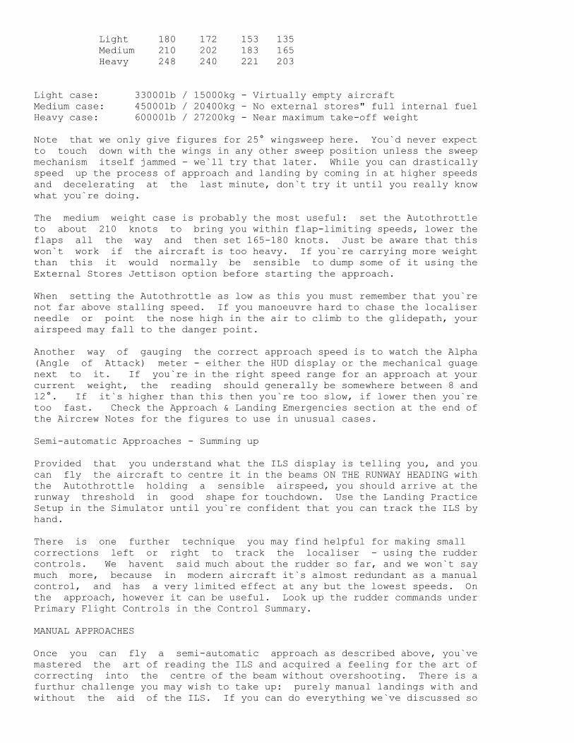
Light 180 172 153 135
Medium 210 202 183 165
Heavy 248 240 221 203
Light case: 33000lb / 15000kg - Virtually empty aircraft
Medium case: 45000lb / 20400kg - No external stores" full internal fuel
Heavy case: 60000lb / 27200kg - Near maximum take-off weight
Note that we only give figures for 25° wingsweep here. You`d never expect
to touch down with the wings in any other sweep position unless the sweep
mechanism itself jammed - we`ll try that later. While you can drastically
speed up the process of approach and landing by coming in at higher speeds
and decelerating at the last minute, don`t try it until you really know
what you`re doing.
The medium weight case is probably the most useful: set the Autothrottle
to about 210 knots to bring you within flap-limiting speeds, lower the
flaps all the way and then set 165-180 knots. Just be aware that this
won`t work if the aircraft is too heavy. If you`re carrying more weight
than this it would normally be sensible to dump some of it using the
External Stores Jettison option before starting the approach.
When setting the Autothrottle as low as this you must remember that you`re
not far above stalling speed. If you manoeuvre hard to chase the localiser
needle or point the nose high in the air to climb to the glidepath, your
airspeed may fall to the danger point.
Another way of gauging the correct approach speed is to watch the Alpha
(Angle of Attack) meter - either the HUD display or the mechanical guage
next to it. If you`re in the right speed range for an approach at your
current weight, the reading should generally be somewhere between 8 and
12°. If it`s higher than this then you`re too slow, if lower then you`re
too fast. Check the Approach & Landing Emergencies section at the end of
the Aircrew Notes for the figures to use in unusual cases.
Semi-automatic Approaches - Summing up
Provided that you understand what the ILS display is telling you, and you
can fly the aircraft to centre it in the beams ON THE RUNWAY HEADING with
the Autothrottle holding a sensible airspeed, you should arrive at the
runway threshold in good shape for touchdown. Use the Landing Practice
Setup in the Simulator until you`re confident that you can track the ILS by
hand.
There is one further technique you may find helpful for making small
corrections left or right to track the localiser - using the rudder
controls. We havent said much about the rudder so far, and we won`t say
much more, because in modern aircraft it`s almost redundant as a manual
control, and has a very limited effect at any but the lowest speeds. On
the approach, however it can be useful. Look up the rudder commands under
Primary Flight Controls in the Control Summary.
MANUAL APPROACHES
Once you can fly a semi-automatic approach as described above, you`ve
mastered the art of reading the ILS and acquired a feeling for the art of
correcting into the centre of the beam without overshooting. There is a
furthur challenge you may wish to take up: purely manual landings with and
without the aid of the ILS. If you can do everything we`ve discussed so

far, you should be able to handle this without too much trouble and no self
respecting pilot should ever be satisfied until (s)he can land with the
absolute minimum of artificial aids The AFDS, the Autothrottle or the
airfield ILS may be knocked out by battle damage. You may have to make an
emergency landing on a airfield, taxi track or a road. In any of these
cases you`ve got to be able to cope. If you can`t, you can only eject -
and throw away an extremely valuable aircraft
Manual Approach with ILS
Here we`re talking about flying an approach without using the Autothrottle.
Managing speed at the same time as flying the approach adds considerably to
the difficulty and demands a quite different flight technique. Normally
you think in terms of controlling speed with the throttle and controlling
rate of descent or climb by pointing the nose up or down. At the low
speeds involved in flying an approach. However, it is actually easier to
reverse this convention. Think in terms of controlling speed by raising
the nose (to slow down) or lowering the nose (to speed up) and controlling
rate of desecent by opening the throttle (to descend more slowly) or
closing the throttle (to descend faster)
Obviously there will be side the nose will usually reduce your rate of
descent as well as your airspeed, and so on, but these side effects are
actually easier to deal with using the reversed convention of airspeed,
pitch and rate of-descent: thrust. Let`s give some examples of how the
process works:
1. Speed correct, but BELOW the glideslope
You respond by throttling up to raise the engine RPM figure one or two per
cent. Now watch your airspeed. As soon as this starts rising above the
target figure, raise the nose slightly to bring the speed back on target.
The end result is that you`re still at the correct approach speed, and
you`re descending more slowly than you were.
2 Speed correct, but ABOVE the glideslope
Throttle back a little. As the airspeed drops below the target, lower the
nose a little to recover the speed.
3 ON the glideslope, but speed LOW
Lower the nose slightly, and watch for the speed to start rising. As it
reaches the correct figure, raise the nose again very slightly. If this
leaves you below the glideslope refer to example 1.
4 ON the glideslope, but speed HIGH
Raise the nose a little till the speed starts to drop. Wait till you`re
close to the target speed and then lower it a fraction to stabilise at the
new speed. If this leaves you above the glideslope, deal with the problem
as in example 2.
It`ll take a lot of practice in the Simulator before you can do this
reliably. To make your initial attempts easier, use a higher approach
speed than normal This will give you more margin for error. You`ll
probably find that the largest problem is the time lag in engine response
to throttle changes, and aircraft response to the change in thrust. For
this reason it`s best to try to avoid large changes of throttle setting
unless absolutely necessary. Having said that there`s no way to avoid one

large throttle movement: your first action in the Simulator Landing
Practice scenario should normally be to close the throttle completely (and
use airbrakes) in order to lose speed. As your speed decays towards the
chosen approach value you will need to open the throttle again, but it`s
best to do this in gradual stages, starting well above the approach speed.
Until you`ve got the feel of the situation its best to be very very
cautious and make the smallest possible control inputs. Line up on the
localiser (left-right reference) first, and then devote most of your
attention to matching the glideslope by juggling speed and rate-of-descent.
Be wary of trying to fly to a fixed rate of descent in feet per second as
shown on the HUD or the VSI; the higher your approach speed, the faster you
must descend to match the fixed 3o glideslope.
This sort of flying takes intense concentration and a thorough practical
understanding of how and why the aircraft responds to the controls. Its
very hard work. If you want a break from the grind, try some purely visual
landings (see below). But if you can learn do this. Be assured that you
could learn to land most aircraft in the real world.
Manual Landings by Eye
Purely visual landings are actually far easier than manual ILS approaches.
Once you`ve got the knack. If you`re going for a straight-in approach
(like an ILS approach) you`ll usually find that it`s best to start closer
to the airfield and higher than usual. This will improve your view of the
runway, and it will also mean that you can fly most of the approach with
the throttle more or less closed, using brief bursts of power to stretch
your glide.
You will probably also find that it`s easier if you fly most of the
approach a little faster than usual, with manoeuvre or mid flap settings
and the gear up. This means that you can drop the gear and the flaps at
the last minute as extra airbrakes, rather than hang about on the edge of
the stall point. Use the Angle of Attack to judge your approach speed.
If you`re really ambitious, you might try a standard military curved
circuit approach. Lining up on the runway from the final 180o turn is more
difficult than in real life because of the restricted and inflexlible views
available from the cockpit - something which we can`t do much about until
Virtual Reality style helmet mounted displays become commonplace.
Once you become accustomed to visual, manual landings you`ll probably find
yourself doing it this way most of the time. The ILS is a godsend in poor
visibility, but it takes a long time to fly the full distance at approach
speeds. You can put the aircraft on the ground much faster for yourself -
provided that you can see to do it.
LANDINGS AND WIND DIRECTION
Up to now we`ve more or less ignored the influence that wind speed and
direction has on landing, but in the real world it`s a major safety issue.
The "Landing Practice" Simulator exercise gives you still air, which is a
very rare situation in real life. In practice the wind direction will
dictate your take off and landing direction and the length of ground run
required.
The reason isn`t all that hard to understand. If an aircraft was flying
straight and level at an Airspeed of 150 knots directly into a
hurricane-force wind blowing at 150 knots, it would be hovering over a

point on the ground. The Airspeed Indicator shows your speed through the
air, which is itself moving over the ground as the wind blows. To take a
more realistic (though still extreme) example, an aircraft flying directly
into a 50-knot wind at an airspeed of 150 knots is actually travelling over
the ground at 100 knots. If that aircraft flew at the same airspeed (150
knots) in the same direction as the 50-knot wind it would be travelling
over the ground at 200 knots. In both cases, the wind speed and direction
make no difference to the flying qualities of the aircraft - its flying the
way you would expect it to at an airspeed of 150 knots. The difference
lies in how fast it`s covering ground.
Speed over the ground makes at least two important differences when it
comes to landing. The first is in the approach. If you`re landing into
the wind, subtracting its speed from your own, the approach will take
longer and you`ll need a lower rate of descent than you would in still air.
This may be tedious, but it`s not unsafe. If you land with the wind behind
you, adding its speed to yours, everything will happen faster and you`ll
need to descend faster than usual to stay on the glideslope. Rushing the
process is clearly not desirable.
The other (and more important) difference comes when you touch down. When
your wheels hit the runway airspeed ceases to matter (you`re no longer
flying), and groundspeed becomes all-important. Landing into the wind your
groundspeed is lower and your landing run shorter. Landing downwind your
groundspeed is higher and your braking distance increases. The choice
should be obvious.
Wind direction also matters for take-off, for similar reasons. If your
aircraft standing on the runway facing into a 20-knot wind, it need only
accelerate to a groundspeed of 130 knots before the Airspeed indicator
shows 150 knots and you can rotate to lift off. If you started with a
20-knot wind blowing past the aircraft from behind, you`d need to roll a
lot further to reach a groundspeed of 170 knots in order to have an airflow
of 150 knots over the wing. Everything which flies and has a brain takes
off and lands facing INTO wind whenever possible. If it isn`t possible,
you may be in trouble.
Crosswinds
When an airfield is built the designers do their best to line up the main
(or only) runway with the prevailing wind in the area, so that most of the
time aircraft will be able to take off and land directly into wind.
Sometimes, however, geography and financial constraints make this
impossible; the longest possible runway on the site just has to run in some
other direction. The wind is also less than 100% reliable, and will blow
from inconvenient directions at least a part of the time.
You can`t usually suspend operations altogether because the wind isnt
cooperating; you just have to make the best of it. Unless the wind is
blowing across the runway exactly at right-angles, which it very rarely
does, you can always resolve it into a component along the runway (a head
wind or tail wind), and a component across it, the crosswind (see diagram
8.21 ). When the time comes to learn about the Mission Planner; you`ll
find that there`s help available to analyse the situation and help you
select sensible take off and landing directions. Here and now we`re
concerned with how to deal with the practical results.
It shouldn`t take much reflection to decide that you want to take off and
land with a head-wind rather than a tail wind. But whatever you do, you`ll
just have to live with the crosswind component. A crosswind component at

take off will make very little difference to a heavy and powerful aircraft
like the Tornado, but a stiff crosswind will make a large difference to
your approach.
There`s a Simulator exercise called "Crosswind Landing Practice" which you
can try out. You`ll find that in order to fly a straight line down the
centre of the beam you will need to keep the nose pointing a few degrees to
the upwind side of the centreline. If you point the aircraft straight down
the beam, it`ll be blown sideways by the crosswind component. Be
especially careful at and after touchdown when flying this sort of approach
- you may need to do some brisk steering to avoid veering off the runway.
If you can afford a good long roll after touchdown, you can mitigate the
effects of a crosswind by flying a faster approach than usual. This will
mean that you can point the nose closer to your intended path. Conversely,
a slow approach with a heavy crosswind will be very difficult to fly
accurately.
LANDING DAMAGED AIRCRAFT
You can practice various emergencies quite easily in the Simulator. Want
to try a wheels up landing? Simple! Just leave the gear up. It is
possible, but you must touch down very lightly. Lighten the aircraft as
much as possible, but you a flapless landing, leave the flaps up. Pretend
that the wing sweep mechanism has failed, and try landing with 45 or 67°
sweep (check the Approach & Landing Emergencies data in the Aircrew
Reference section first!). Try a landing with the engines at idle thrust
without touching the throttles.
For a real dead-stick landing, do a maximum jettison then light up full
reheat to burn off the remaining internal fuel. Keep the aircraft at low
level and that won`t take long. When the engines flame out, zoom-climb the
aircraft to turn as much speed as you can spare into altitude. If you can
find a runway, well and good - if you can reach it. If not, it`ll have to
be a road. Try to find a stretch without bridges. Obviously the aircraft
will glide furthest in a shallow dive at 25 sweep, but that`s not saying
much - no fast jet glides well. Hold off on the flaps and the gear to the
very last minute unless you have speed or altitude to burn.
There is also a special-purpose Simulator mission called "Single Engine
Handling" - try it. If you examine the Control Summary you`ll find that
you can turn off the HUD, the MFD or the back-seat Tab displays. Flying on
the panel instruments without the HUD is difficult but possible, and an
excellent way to put some excitement back into the job of landing if you`re
beginning to find it too easy.
On Damaged Runways
Don`t forget that while you`re off trying to crater the enemy`s runways he
may visit your home airfield to return the compliment. Apart from leaving
your gear up, it`s hard to think of a more humiliating way to end an
otherwise successful mission than to land perfectly and then run the
aircraft into a hole on the roll out. Keep your eyes open on the approach,
and use the forward looking camera at night. If your runway is damaged,
you`ve either got to stop before, land after or swerve around the craters -
or land on another runway. If you dont want to divert or you can`t for
lack of fuel, you must either land on one of the long taxiways or use a
disused runway (these are the ones with white crosses at the threshold).
Provided that they haven't been damaged in the attack, these surfaces
should be perfectly suitable, though respectively narrower and shorter than
the main runway, and of course there`s no ILS. Watch out for taxying

aircraft on the taxiways and parked aircraft on the disused runways. In
the Simulator there's nothing to stop you trying a landing like this at any
time If you really want to get into the spirit of the thing you might try
attacking your own airfield and then landing - it'll give you a whole new
perspective on JP233 attacks ln the last resort you can always try landing
on a nearby road.
EMERGENCIES
Emergencies divide into two rough categories; recoverable ones which offer
some prospect of saving the aircraft as well as yourself, and those where
you must abandon the aircraft in order to save your life. The tricky part
is deciding which kind of emergency you`re facing, and doing so fast enough
to take the appropriate action in time.
Emergencies include systems failures and loss of control for any reason
We`ve already dealt with stall recovery, and suggested Simulator exercises
to practise landing with various equipment failures. If you make yourself
familiar with the controls available you can simulate and try out a great
many system failures, and the exercise can only do you good.
Here we`ll discuss three topics;jettisoning stores to lighten the aircraft
ejection and spin recovery drill. Jettisoning weight will usually mean
aborting your mission, but it will always improve the performance of the
aircraft if you still have control. Ejection is always the right response
in any of the following situations; Engine Fire, permanent loss of control
at any altitude, any loss of control at low altitude. The Tornado will
never spin unless the SPILS system is disabled or damaged, but when it does
the recovery technique is highly unconventional.
Jettison Options
There are three graduated jettison commands, and three matching lights on
the Front Panel. In increasing order of severity these are:
Jettison External Tanks only
Releases the drop tanks on your inboard pylons to save weight and drag. If
the tanks are empty then you improve performance and range at the expense
of losing re-usable tanks, the supply of which is not infinite. If the
tanks still contain fuel then the relative performance improvement will be
far greater, but you will probably have sacrificed range or endurance.
This may prevent you from completing your mission, or returning from it
safely, but if a Tornado is involved in any kind of close air combat your
chance of surviving, let alone winning is not good unless you dump as much
weight as possible.
The green Jettison light illuminates to confirm separation
Jettison Tanks and Offensive Stores
This is the option you need if hard-pressed by an enemy fighter in close
combat, or in the event of engine damage. It dumps all external stores
except AIM9L air-to-air missiles for self-defence.
The amber and green Jettison lights illuminate to confirm separation.
Jettison All External Stores and Internal Fuel down to 1000 lbs / 450 kg
This option is intended for use just before landing a damaged aircraft, if

the situation demands it. All external stores are dumped without
exception, and all internal fuel bar 1000lbs with which to complete the
approach, leaving you with an aircraft in its lightest possible powered
configuration.
The red, amber and green Jettison lights will all illuminate to confirm
that the stores are gone and the fuel dumped.
Ejection
Ejection itself is a very simple action once activated. The system thinks
for itself and does its best to maximise your chances of survival right up
to the point when it opens your parachute for you. However, it`s still up
to you to decide when to pull the handle. You must decide for yourself
whether a) the situation is so dire that you must eject now or you
definitely won`t survive, b) with the aircraft in its current attitude you
probably won`t survive ejection, or C) the aircraft will probably stay in
one piece, under control, for long enough to allow you to manoeuvre to
improve your chance to survive or avoid capture
There are two situations in which ejection is definitely the only way out.
These are an engine fire, which (for our purposes) will always result in a
catastrophic explosion within a few seconds, or a loss of control with no
prospect of recovery before the aircraft hits the ground. If and when an
engine fire is detected the warning system will go off and the condition
will be flagged on the Warning Panel in the back cockpit. Loss of control
can occur in many different ways, but you will probably be in no doubt when
it occurs. All that remains is to decide whether your chances will be
improved by waiting and normally, they wont.
The Tornado`s ejection seats, like those in almost all modern combat
aircraft have what is called a zero / zero capability the zeros are for
altitude and airspeed. In other words, you can eject from a motionless
aircraft on the ground and expect to survive. The seat contains a rocket
motor to lift you and throw you far enough away that a) your parachute has
time to deploy before you hit the ground and b) with any luck you won`t
come straight back down on top of the burning wreckage of your aircraft.
The seat is quite smart, and will do its best to tailor its response to the
situation but there are unavoidable limits to what you can expect. Because
the ejection system fires the seats upward from the cockpit, ejecting with
the aircraft inverted is suicidal at low level.
At the other end of the scale, ejection at a high Mach number is also risky
because of the appalling air blast. Another hazard is involved because
high speed usually means high altitude. The seat mechanism contains an
automatic opening device which will normally delay the deployment of your
parachute till you have fallen to a survivable altitude (10000-20000 feet
might be a common setting) and decelerated to a sensible speed. The
mechanisms involved are simple, robust and highly reliable, but they are
not immune to damage - and they are designed to fail safe. If possible.
For an automatic parachute opening device, failing safe means deploying the
parachute sooner rather than later (or not at all). All parachutes open
harder the higher the deployment altitude, and a high-speed opening at high
altitude may cause serious injury or death through opening shock (even in
the normal case this might involve a 20 G jolt), or through the risk of
anoxia and exposure on the way down.
If time and the situation allow, the best way to maximise your chances is
to eject at low speed (up to 300 knots, say) at a moderate altitude (say
10000 to 15000 feet). When all is sad and done, however, there are many
situations where ejection is the only option you have left, and if you
don`t pull the handle straight away you won`t get another chance.
SPILS, SPINS AND SPIN RECOVERY
The Tornado, like all modern combat aircraft, has a sophisticated flight
control system. In simple aircraft the pilot`s controls are directly
connected to the control surfaces of the wings and tail, which are moved
either directly by the pilot`s muscles, or by a servo system which uses
hydraulics to boost muscle power. In more sophisticated aircraft like the
Tornado, the pilot`s controls are not directly connected to the control
surfaces. Instead, the pilot uses the controls to tell the flight control
system what he wants the aircraft to do and the flight control system then
decides for itself how to move the control surfaces in order to carry out
the pilot`s command.
Without systems of this sort, modern combat aircraft could never have
achieved their current high standard of agility. They are agile because
they are unstable; a small control surface movement can produce a radical
change of attitude, and they have no inherent tendency to fly in a straight
line, or even the right way up Flying such an unstable aircraft by hand
would be like walking a tightrope in a high wind; even if you could do it,
the effort, concentration and stress would exhaust you in a few minutes.
When the flight control system is working, it constantly senses the
aircraft`s departures from the commanded flightpath and makes minor
adjustments of the control surfaces to correct them before the pilot even
has time to notice.
Extra protection is often built into such a system to enable the pilot to
manoeuvre the aircraft aggressively and confidently right up to the extreme
limits of its performance (as in air combat), while the automatics keep the
G load within the structural limits and monitor the angle of attack. If
the aircraft stalls despite all their efforts, such systems will then do
all they can to keep the aircraft stable till it regains flying speed. The
system which provides this extra safeguard in the Tornado is called SPILS,
standing for Spin Prevention and Incidence Limitation System.
Spinning
Spinning is a hazard associated with stalling. When the airflow over the
wings and the tail breaks down the aircraft is left falling through the air
rather than flying. If the aircraft is rolling or yawing (changing heading
without banking) when control is lost, a complex combination of
aerodynamic, inertial and gyroscopic forces may arise in which the whole
aircraft either rotates constantly round one or more axes (a steady spin)
or alternates between two unstable positions (an oscillatory spin). In
this situation normal flight control just doesnt exist, and the aircraft is
falling rapidly out of the sky.
Fast jets with swept wings have the most vicious spin characteristics of
any aircraft, and some are impossible to recover - all the pilot can do is
eject. When it is working, the SPILS system in the Tornado detects any
incipient spin problem at the stall point and acts to correct it before the
spin can become established. Like any other system in the aircraft,
however, the SPILS system may be disabled by combat damage or random
failure. If this happens any stall may develop into a spin - so you need
to know how to recover once the spin has started.
Spin Recovery

The Tornado`s spinning characteristics and recovery drill are unusual for
two reasons; first, it is a swing-wing aircraft and the nature of the spin
changes with wing-sweep setting; second, it is unlike most other aircraft
in that it has no aileron control surfaces on the wings, moving the tail
surfaces differentially instead. If you are an experienced pilot of other
aircraft types, DON`T ASSUME THAT YOU ALREADY KNOW THE RECOVERY DRILL!
Let`s set up the problem in the Simulator Select one of the Free Flight
(Airborne) exercises. When you arrive in the cockpit, turn off the SPILS
system. This should probably be done with the Control+I key combination,
but check with the Control Summary for your machine (Secondary Flight
Controls section). Be careful when doing this: just hit the key once,
because the control toggles SPlLS on / off and there`s no indicator apart
from the one on the wings right back panel in the back, which only
illuminates when the system fails due to damage and NOT when you switch it
off deliberately. Now sweep the wings right back to 67°" cancel
Autothrottle and go to full reheat (Slam Open twice). Let the aircraft
accelerate to high speed on the level, then cancel reheat (just Slam Shut
while in reheat). Leaving the throttles at Max. Dry power (100% RPM).
Pull the aircraft up into a near vertical climb and take your hands off the
controls.
The aircraft will zoom-climb to a high altitude, losing speed rapidly. At
about 220 knots IAS you should see the nose begin to drop in the stall.
Now apply full sideways stick - the direction doesn`t matter. Suddenly the
aircraft goes crazy - the HUD references and the instruments are all over
the place and the horizon flashes past your nose at short intervals and
strange angles. Hit F1 for an external view and you`ll see that the
aircraft is tumbling end over end in all three axes as it falls. This is
characteristic spinning behaviour when the wings are fully swept.
Now hit the Sweep Forward key twice, to bring the wings to 25 sweep. As
the wings move forward you should see the wild tumble stabilise into a
rapid rotation. If you move back to the cockpit you will see that the
horizon is now fairly stable, but the aircraft is twirling like a
propeller. In order to recover from the spin you must first identify which
way the aircraft is rotating. This one excellent reason why you should
bring the wings to 25 sweep first, because it is extremely difficult to
tell which way you`re going if the aircraft`s in a full blooded tumble.
Having identified which way you`re turning: APPLY AND HOLD FULL BACKWARD
STlCK AND PRO-SPlN AILERON! In other words, hold the stick right back and
to the side you would normally use to bank in the direction you`re already
turning. This is almost the exact opposite of the spin recovery drill used
in most aircraft, which is classically performed by centering the stick,
pushing it forward and applying opposite rudder. This classical procedure
is utterly useless in a spinning Tornado.
Having applied full backward stick and pro-spin aileron, you will need to
hold the stick in this position for a variable length of time, which will
never be less than a couple of seconds and sometimes a good deal longer.
Meanwhile watch the Altimeter and the Airspeed Indicator. Standard
Operating Procedure in the Tornado is to eject immediately if the aircraft
enters or continues a spin below 20000 (yes, twenty thousand) feet, but you
may find that you are willing to continue recovery procedures below this
height after you have some experience. The decision is entirely up to you.
In a steady spin the Airspeed Indicator will show a very low figure, far
below normal flying speeds. One of the first signs that the recovery
process is working will be a steady rise of speed. As the figure climbs

towards the normal ranges you should also see that the rotation rate is
slowing. When it stops, the aircraft is under control again, so
immediately center the stick and (if you can still afford the height loss)
push the nose down to accelerate faster.
Here`s the Spin Recovery Procedure again, in short form:
Once you realise that the aircraft is spinning:
1 Eject immediately if there is insufficient height for a recovery (say
20000 feet), otherwise monitor altitude closely throughout the recovery
process.
2 Command full forward sweep to 25°.
3 As soon as the direction of rotation is identified, apply and hold full
backward stick and pro spin aileron.
4 First sign of recovery will be a sustained increase in airspeed.
5 When rotation ceases, accelerate to a safe speed as quickly as possible
EXTERNAL VIEWS
--------------
Although "stepping outside" as you are flying along is not exactly
"authentic", a different perspective on a problem can often be useful and
let`s face it - its fun! We have included no less than six "external
views" that range from the commonplace to the spectacular. A status line
at the bottom of the screen shows your aircraft speed, altitude etc.
(a) Tracking view
Perhaps most common of all is the option to "step outside.. your cockpit"
and watch yourself fly along. When first selected, you will be positioned
immediately behind your aircraft, following at a fixed distance. If your
prefer, you may use the zoom in and out facility to adjust your perspective
at either normal or fast rate.
When you`ve had enough of looking at tailpipes, try the "adjust tracking"
controls. These allow you to swing your viewpoint around your aircraft in
either direction, quickly or slowly, to give you a full 360° outside view.
The "reset" option will position you behind the aircraft again and for good
measure we have the "toggle lo/hi" feature which puts you level with your
aircraft or slight below it.
It is worth mentioning that when you leave Tracking View, your viewpoint
and zoom level are stored so that when you next select this option your
viewpoint appears just as you left it. For example, if you wish to watch
an attack from a particular angle say looking back at your aircraft from in
front and below - you can set the viewpoint in advance, fly the attack, and
then switch to Tracking View at the moment of weapon release.
(b) Satellite view
Select this option for a bird`s eye view looking directly down onto your
aircraft. Select again and you`ll get a worm`s eye view looking up from
underneath! We do not recommend this second option when sitting on the
runway as all you will get is a close-up of the underside of the fuselage.
The plan view though is very handy when taxiing around the airfield. We
suggest that you zoom out to a reasonable height in order to see ahead of
your aircraft.
(c) Remote view
This option allows you to hop outside and watch your aircraft from a fixed
position. The viewpoint is fixed at the position of your aircraft at the
moment of selection, and turns to follow your aircraft as you manoeuvre.
This gives a superb impression of the true speed of your aircraft and is
great fun if you wish to brush up your radio control techniques but it`s
very easy to get disorientated or lose sight of yourself altogether.....
(d) Drone view
"Drones" are the numerous computer-controlled aircraft and ground vehicles
moving around the combat area simultaneously to yourself. By repeatedly
pressing "drone view select" you may observe their activity and impress
your friends. Zoom and track controls are available. You may also switch
between allied and enemy drones, aircraft or ground vehicles.
(e) Weapon view
What better way to approach a target than alongside your weapon? Again
zoom and track adjust is available. Just prior to impact, air to ground
weapons will switch to a plan view to help assess accuracy of delivery.
(f) Spectator view
Spectator view isn`t strictly a separate view mode - it`s an extra twist
you can apply to any other view mode to achieve cinematic effects. When
you select Spectator view, the viewpoint is "frozen" in space wherever it
happens to be at that moment (unless it`s already a Spectator view), while
the action carries on.
For example, you could call up the Tracking view. Move it around ahead of
the aircraft and zoom it out, then select Spectator view and watch the
aircraft approach and flash past the stationary viewpoint. If you select
Spectator view again as the aircraft passes, the view point will be frozen
at the aircraft position again, but this time watching it recede into the
distance.
You can use the track adjust controls to rotate a Spectator view, and once
you have set up the camera angle to your liking, return to the cockpit to
fly the aircraft back into shot. Selecting "restore Spectator view" will
put you back at your chosen spot to watch the effect.
If we tried to describe all the tricks you can play with Spectator view, it
would rate a substantial chapter on its own. You`ll have to experiment for
yourself and use your own imagination.
WEAPONS CONVERSION
------------------
When a pilot under training has reached the stage where flying the aircraft
to its safe limits does not demand 100% attention, it`s time to start
learning how to fight. The RAF call this phase of training Weapons
Conversion. There are two very different subjects to cover: ground attack
and air combat. In this chapter we`ll also be looking at how to use the
Tornado`s radar in both its air and ground modes, and the Radar Warning
Receiver. In the process we`ll be considering a variety of tactical and

operational problems.
AIR-TO-GROUND
The Tornado IDS was built to deliver the largest practical load of the
cheapest, simplest weapons as accurately as possible regardless of weather
and visibility. You may well be surprised at how accurately simple "dumb"
bombs can be placed by a smart bombsight. In addition, three special
grounds attack weapons are available, two of which are smart. You will
need to understand the nature of each weapon, when and why to use it, and
how to deliver it. First we`ll look at the list of air to-ground weapons
The Weapons
1000 lb. General Purpose Bomb (GPB)
A plain and simple unguided bomb, effective against a wide variety of
targets. Quite effective against a hardened target provided you can hit
it, and the blast and fragments will affect softer targets (most vehicles,
aircraft etc) over a fair radius. GP bombs are the cheapest of all major
ground-attack munitions, so large stocks are available. They also allow a
wide variety of delivery methods, so a good deal of flexibility is
available in trading off accuracy against risk. Usually delivered four at
a time.
1000 lb. Retarded Bomb (RET)
These are 1000 lb. GP bombs fitted with an alternative tail section
incorporating a braking parachute. This means that they can be dropped
safely from much lower altitudes than Gp bombs, since the aircraft is much
further ahead of the bomb by the time it hits the ground (see diagram
10.1). Minimum dropping height for Retarded Bombs is 100 feet (just enough
time for the fuse to arm), as against 1000 feet for unretarded GP bombs.
Because the retarder hit is a cheap and simple fitting for a cheap and
simple bomb, they are usually in good supply.
1000 lb. Laser Guided Bombs (LGB)
The original "smart" bomb. This is actually another special kit fitting
for a standard bomb carcase, providing a nose assembly containing the laser
seeker and control surfaces, and a tail with flip-out cruciform wings
giving it the ability to glide further than a standard bomb. LGB are used
in conjunction with the launching aircraft`s TIALD system. The navigator
slews and zooms his camera view to place the aiming crosshairs on the
precise point he wants to hit, which is illuminated by the laser designator
in the TIALD system. The seeker in the nose of the LGB "sees" the spot of
reflected laser light and tilts the bomb`s nose control surfaces to steer
towards it. Phenomenal accuracy is possible - missing the target spot by
as much as five feet would be a very poor performance.
This degree of accuracy makes laser-guided bombs the ideal weapon against
hardened installations or major bridges, which must be hit with extreme
precision to cause more than superficial damage. The downside is that the
designating aircraft must fly quite slowly at medium-to-high altitude in a
fairly straight line for twenty to thirty seconds in order to keep its
designator on the target till the bomb hits, and if there is cloud in the
way the laser couldnt illuminate the target even if the TIALD operator
could see it. Laser guidance kits are not cheap, and therefore not all
that plentiful, but on the other hand, few weapons are as efficient and
cost-effective; use it properly and every bomb scores a direct hit.
BL755 Cluster Bomb
Looks like a plain bomb, though less well streamlined is actually a casing
for many smaller bombs (submunitions). After dropping, the case splits
open at a preset height (set at 150 feet in Tornado) and ejects the
submunitions in a dense cloud. If properly delivered, a salvo of four will
devastate all but the hardest targets in a "footprint" perhaps 100 feet
across by 300 feet long. This is the weapon of choice against groups of
vehicles or parked aircraft. Its main drawback is that it must be
delivered from about 200 feet for maximum effect (see diagram 10.2)
JP,233 Dispensers
This is the mother and father of all runway-attack systems, the Tornado
version comprising two giant pods weighing a total of nearly five tons!
The pods contain two types of submunition: 60 large (56 lb.) SG.357 runway
penetrators and 430 small HB.876 "area-denial" mines" both types parachute
retarded. As the aircraft overflies the runway, the submunitions are
continuously ejected in a stream. When the runway-penetrators reach the
surface, a shaped charge punches a small hole right through the concrete
and a second charge is then fired into the hole, exploding beneath to crack
and "heave" the surface over as wide an area as possible. This type of
damage is far more difficult and time- consuming to repair than a simple
crater. Meanwhile the smaller mines land softly, discard their parachutes
and spring upright, deterring and delaying repair through the deadly danger
they present to men and vehicles.
JP.233 will make a really impressive mess of any runway if used properly.
Its main disadvantage is the fact that the delivering aircraft has to
overfly the target at low level holding a straight course for the four
seconds needed to dispense the whole load - manoeuvering strews the things
all over the place! It is also a Heavy, draggy load for the aircraft,
though the pods jettison automatically when empty.
ALARM (Air Launched Anti-Radiation Missile)
ALARM is probably the most capable and sophisticated missile of its type
currently in service (the US Tacit Rainbow project had even more ambitious
aims, but died the death of a thousand budget cuts). Like any other anti
radiation missile ALARM homes on the transmissions of enemy ground radars
(EWR, search, SAM or AAA radars, for example) in order to destroy them, but
it is far more resourceful than most
ALARM has many different operating modes, some of which are classified but
we have implemented two which seem most characteristic and useful. One is
a simple Direct mode, allowing ALARM to be used like any other anti radar
missile. In the other mode (Indirect) ALARM can be launched at distant
suspected targets before you reach them or they see you. When the target
is reached, the missile will zoom-climb to a point high above it, shut down
its rocket motor (if it`s still burning) and deploy a parachute. It then
loiters nose down, descending slowly and scanning the ground beneath. If
any hostile radar is switched on, ALARM jettisons the parachute and falls
on the target like a guided bomb.
Weapon Packages and the Stores Management Display (SMD)
Weapons for ground attack are grouped together in "Package". One package
contains all the weapons intended for one target, which will be released
together as a salvo. You might, for example, load a package of four

retarded bombs for a planned attack on airfield installations, and a second
package of two BL 755 to attack targets of opportunity. The maximum number
of weapons in a single package is four, and all must be of the same type if
they werent the bombsight would lose its accuracy because different weapons
have different ballistic properties.
The content and status of any weapon Packages loaded can be seen on the
Stores Management Display (SMD), bottom centre in the rear panel, where
each of the top three lines can describe a single package. Suppose that
the top line reads:
X GPB1000x4 LFT
This specifies from left to right the target, if any, for which the package
is intended (X). The type of weapon (GPBl 000), the number in the package
(x4) and the Delivery Mode selected (LFT). The Delivery Mode specifies
whether you intend to use manual or automatic release, a laydown or loft
trajectory a laser guided attack. Some weapons, like JP.233, have only one
delivery mode available. Others, like GP bombs, offer several options.
When you start your attack run and flip the "arm air to ground weapon"
switch. the HUD will display different aiming cues according to the
delivery mode selected. We will explore the various delivery mode options
later, in detail.
Packages are created at the Mission Planning stage, either when you plan an
attack on a specific target, or when you use the Payload window to create
packages to use against Targets of Opportunity. If you planned attacks on
two targets (X and Y) in one mission, and then loaded one more package for
opportunity targets. When you looked at the SMD the first line would show
the package for target X. The second line the package for target Y, and
the third line the Target of Opportunity package, with a dash ("-") on the
left rather than a letter.
The currently selected Package is shown highlighted. When you turn the
arming switch on, this is the package that will be used in the attack, and
the appropriate line on the SMD will flash continuously. When the package
is released the Arm status cancels itself, the HUD resets to its normal nav
mode the package disappears from the SMD and the next package is selected
and highlighted, ready to be armed.
You may override both the assignment of packages and the delivery modes,
attacking any target with any package, using any delivery mode suitable for
the weapons in the package. Hitting the K key will select and highlight
the next package down the list, or skip from the last to the first.
Hitting the L key will cycle through the available delivery modes for the
currently selected package. You cannot do either of these things when the
arming switch is on - if you want to change package or delivery mode you
must hit "Cancel Arm" first.
The Delivery Modes
This section provides a brief summary description of the various methods of
placing freefall bombs on the target. After this familiarisation, we`ll go
through a complete hands-on exercise with each weapon and mode in turn.
Manual (SMD shows MAN)
This is a simple "point and shoot" system intended for snap attacks on
targets of opportunity. The HUD provides a bombsight, but aiming and
release are entirely manual.

GP bombs, retarded bombs, BL755 and laser guided bombs (unguided) can all
use manual delivery.
Laydown (SMD shows LAY)
Targets for this delivery mode must be entered into the navigation systems,
either at the mission planning stage or "on the fly" using the Ground radar
or the Scrollable Map display. The HUD shows the bombsight and a marker
over the target, and the attack run can be flown manually or under AFDS
control. The exact moment of weapon release is automatically calculated
but the weapons cannot be released unless one of the crew is holding down
the Commit button.
Strictly speaking, a laydown delivery means releasing the bombs with the
aircraft flying straight and level, but the bombsight systems will handle
dive attacks or shallow lofts perfectly well in this mode.
GP bombs, retarded bombs, BL.755 and laser-guided bombs (unguided) can all
be delivered in Laydown mode
Loft (SMD shows LFT)
Targets for loft attacks must be known to the nav systems. As for Laydown
mode. This type of attack is sometimes also called "toss-bombing", because
the bombs are thrown rather than dropped. The aircraft starts its attack
run a good way out from the target, and while it is still miles away it
pulls sharply up into a climb. The bombs are released in the climb and the
aircraft is free to go while the bombs fly on for several miles, rising and
then falling onto the target in a trajectory like that of a long-range
artillery shell. The bombsight cues on the HUD are quite different from
the Manual or Laydown sights, and the attack profile can only be flown
manually - unfortunately the AFDS can`t fly the pull up for you. Release
is automatic, but only permitted if the Commit button is held down.
BL 755 cluster bombs are too aerodynamically "unclean" to be lofted
accurately and lofting retarded bombs would make about as much sense as
trying to pole vault with a ball and chain round your ankle, so Loft
delivery is only available for GP bombs and (unguided) laser guided bombs.
Laser-Guided (SMD shows LGB)
An LGB attack is run entirely by the navigator, who must use the TIALD
system to aim the laser designator at the precise spot he wants to hit.
The laser guided bombs are normally released in level flight at over 20000
feet, in order to allow the TIALD system the widest possible view, and
after release they aim themselves at the laser illuminated spot on the
target. The aircraft is normally flown by the AFDS for this type of
attack, but target designation and the release of the bombs can only be
performed manually.
Unsurprisingly, this delivery mode can only be used for laser-guided bombs.
WEAPONS TRAINING IN THE SIMULATOR
The Simulator provides the ideal environment for practicing any kind of
attack. You can start in mid-air, not far from the target, and there is
even an "infinite weapons" option which instantly replenishes any package
used. Select the Simulator from the Flight options, and look through the
options on the Mission Selection Screen until you find the mission titles

with the letters TWCU - for Tornado Weapons Conversion Unit. Select the
first of these, titled "IDS - TWCU Freefall Bombs". Make sure that the
Simulator Options switch for infinite Weapons is ON. Now Commit, and you
will move straight to the aircraft in flight. Engage the AFDS in Track
mode - you will find yourself Terrain-Following at a ride height of 1000
feet.
Switch to the back seat and you will see from the Track display on the left
Tab that the aircraft is approaching the Initial Point for an attack on
target X. On the SMD you will see that the first package is selected; four
GP bombs for Laydown delivery There are two other packages loaded, one with
two retarded bombs, and one with two BL.755 cluster bombs. For the moment,
we`re going to attack target X as planned, with the four GP bombs.
Laydown Attack (LAY on SMD)
Laydown bombing is "traditional" bombing, where the aircraft flies more or
less straight and level over the target to release its bombs. Lining up on
the target is the responsibility of the pilot (or the AFDS in Track mode),
but the exact moment of bomb release is controlled automatically by the
bombsight. The automatic release will not occur, however, unless the pilot
or navigator permits it by holding down the Commit button. Laydown bombing
is potentially very accurate at low level, since most pilots find it quite
easy to line the aircraft up on the target, whereas judging the exact
moment of release by eye is difficult to do consistently.
Wait until the aircraft passes the Initial Point and starts turning towards
X. The first thing to do is hit the "arm air-to ground" switch, which you
can do from either seat. From the back seat, you`ll see the selected
package on the SMD start flashing. In the front seat you`ll see the Late
Arm Switch cover raised, and the HUD mode will change to show the Bomb Fall
Line, the CCIP (Continuously Computed Impact Point), and the Target Marker,
which may well be partly hidden behind the Bomb Fall Line (see diagram 10,4
to find out which is which).
For the moment the autopilot has control, but to do this manually, your
first step would be to line up the Bomb Fall Line so that it passes through
the Target Marker. The upper end of the Bomb Fall Line provides you with a
Safety Height Cue. So that the aircraft isn`t damaged by flying debris as
the bomb goes off, You can see how this works in diagram 10.5. If you
can`t see the Bomb Fall Line at all, you"re far too low - it's disappeared
off the bottom edge of the HUD! The ideal minimum height attack is flown
with the top of the line right in the centre of the Target Marker, but for
now you might want to allow the normal training safety margin, with the
Target Marker in the gap below the top of the Bomb Fall Line.
The CCIP is the other element of the bombsight symbology. The point where
the CCIP line crosses the Bomb Fall Line is the point where a bomb would
hit if released now. In Laydown attacks, the release is automatic when the
CCIP reaches the Target Marker, but the symbol serves to show you how close
you are to release. Shortly before the CCIP reaches the Target Marker, you
must press and hold the Commit button to permit the automatic release.
When release takes place, the HUD changes back to normal navigation mode,
and the Late Arm Switch flips back down.
If you hit the Weapon View key just after bomb release you`ll be able to
enjoy a bomb`s eye view of the approaching target, followed by a plan view
at impact. It`s a good idea to ensure that the aircraft is in a sensible
autopilot mode before you go sightseeing.
Having flown the attack under automatic pilot in order to see what it
should look like, try it again manually. You can quit and restart, or turn
the aircraft around and come back to X, or you can use the Scrollable Map
to set up a Target of Opportunity waypoint to attack (don`t forget to
select T). If you want to make another pass on X, you`ll need to hop into
the back cockpit and check that waypoint X is still the currently selected
(highlighted) waypoint. If it isnt, use the skip to next waypoint, key to
cycle round until it is. For each fresh attack you`ll need to hit the
arming switch to arm the release system and call up the bombsight
symbology. Because you`ve selected Infinite Weapons, you wont need to make
any new selections on the SMD - your GP bombs will be replaced the moment
they`re dropped.
Once you`re comfortable with the bombsight, try the same attack with
retarded bombs and BL.755 cluster bombs. Just use the K key to highlight
the right package, but remember that you can`t do this while the arming
switch is ON.
The main difference you`ll notice is that the Safety Heights for these two
weapons are much lower than for GP bombs.
We talked in Advanced Flying Training about how to set a Target of
Opportunity waypoint using the Scrollable map. There are two other ways to
set a ToO waypoint, one of which is to use the Ground Radar, which we`ll
look at here.
Designating a Target of Opportunity on the Ground Radar
This can be done from the front or back seat. Hit the R key to turn on the
radar and show the radar image on the centre MFD. This is not a pure radar
image but a synthetic composite. The landscape and fixed objects known, to
the digital map system are always shown in dim green shades. When the
radar detects an object which is not in the map database it displays it as
a bright green dot. This is especially useful for finding vehicles
(including SAM and AAA defences) and trains. Note that the radar can`t see
through hills. In the dead ground, behind a crest the display will show
you only stored map data.
The mouse is used to control a designator cross which can be moved around
the display check that the MFD`s green Mouse Active light is on, and if
not, use the Tab key to turn it on. Just as with the Local Map display,
the radar display can be zoomed in or out by clicking left or right mouse
buttons with the Ctrl key held down, and targets are designated by clicking
left or cancelled by clicking right.
Remember that using the ground radar may draw the attention of the enemy,
if he hasn`t already seen you. If you select another MFD display while the
radar is on, there is a warning light on the panel to remind you that your
radar is still transmitting. Always turn the radar off if you don`t need
it.
Manual Delivery (MAN on SMD)
This is a simple "point-and-shoot" system intended for snap attacks on
targets of opportunity when there is no time to designate or the target is
moving. The HUD displays the Bomb Fall Line and the CCIP (Continuously
Computed Impact Point) across it, showing where the bombsight thinks your
bombs would go if released at this moment. No Target Marker is shown,
because you haven`t told the navigation systems where the target is. You
just fly the aircraft to place your visually selected target at the

intersection of the two lines, and then press the Commit button to drop the
bombs. The important difference between the symbology used here and in the
Laydown mode is in the way you interpret the Safety Height cue. In Laydown
mode you compare the top of the Bomb Fall Line with the position of the
Target Marker, but in Manual mode there is no target marker, so you compare
the top of the Bomb Fall Line with the position of the CCIP (see diagram
10.6). At low level you can achieve quite reasonable accuracy in Manual
mode, but it`s not exactty precision bombing.
To change the delivery mode; go to the back cockpit and highlight the
package you want to use using the K key, then hit the L key repeatedly to
cycle throught the delivery mode options for that package until you reach
MAN. As with any weapon delivery mode, you must Arm before you can drop
the package.
Loft Delivery (LFT on SMD)
A Loft attack (you might have heard this called toss bombing.) also
requires that the target position should be known to the navigation
systems. A Loft attack comes in two phases; in the first you run in at low
level and fairly high speed starting a good distance (say 10 miles) from
the target; you line up the Bomb Fall Line with the Target Marker and wait
for a 'countdown clock' on the HUD to count down to zero. When that
happens, the second phase starts as the HUD changes to display a "rubber
triangle" steering cue and another countdown clock. You pull up into a
climb, trying to place the cross at the apex of the triangle (the Apex
Marker) in the centre of the aircraft datum ring. As you do, the clock
winds down. When it reaches zero the bombs are released (provided that the
Commit button is down) and you are free to get the aircraft out of the way.
The bombs fly on, rising to the top of a long arc and then curving down on
or near the target.
In a typical Loft attack, an aircraft running in at 550 knots at 200 feet
would start its pull-up about five or six miles from the target and release
its bombs just below 1000 feet, climbing at an angle of just over 20o -
still four or five miles from the target. The bombs would take about 20-25
seconds to reach the target, climbing to 8-9000 feet before they start to
descend.
In a Loft attack, the bombs travel a very long way from the release point
with no form of guidance, so absolute accuracy can`t be guaranteed. In
practice, however, you`ll be amazed at how much accuracy is possible.
Nonetheless, Loft bombing is not recommended for precision attacks. The
great advantage of this form of attack is that the aircraft need not
overfly the target, and may never even come within range of its defences.
Restart the Simulator "Freefall Bombs" mission, engage AFDS Track mode and
switch to the back cockpit. The first package, (four GP bombs) is already
selected and the delivery mode is shown as LAY. Hit the L key to cycle
around the delivery options until the display shows LFT. When the aircraft
turns to run in on target waypoint X, hit the arming switch. The HUD will
now show the Target Marker, a solid Bomb Fall Line, and a Countdown Clock
slowly unwinding anti-clockwise around the Aircraft Datum. Use the Bomb
Fall Line to line up on the Target Marker, or let the AFDS do it in Track
Mode, and whether manually or under AFDS, set your altitude to about 200
feet and your airspeed to about 550 knots. The Clock is counting down to
the point where you start pulling up into a climb in order to loft the
bombs. This point, the Pull up Point, is constantly recalculated on the
basis of range to the target, speed (the faster you`reflying the further
you can throw the bomb) and altitude (the higher you are, the furthur the

bomb will fly). The Pull-up Point is determined by the maximum range at
which your lofted bombs could reach the target if released at your current
height and speed in a 45° climb. This is the climb angle at which you
would achieve the theoretical maximum range.
As the Countdown Clock approaches zero, stand by when the Pull up Point is
reached. The HUD symbology changes, to show another Countdown Clock and a
"RubberTriangle" steering cue. The Clock shows the difference between the
range to the target, and the distance your bombs would be thrown if you
released them now. The steering cue directs you to pull up and steer left
or right as necessary to stay lined up with the target; the small cross
(the Apex Marker) moves up and down, left and right relative to the
Aircraft Datum, the base line of the triangle is fixed and the middle
horizontal line is drawn halfway between the two, skewing right or left as
the Apex Marker moves. The position of the Apex Marker in relation to the
Aircraft Datum tells you which way to steer - when you`re pointed exactly
the right way, the Apex Marker is in the exact centre of the ring of the
Aircraft Datum.
Assuming that you are still well lined up on the target, the Apex Marker
will be directly above the centre of the Aircraft Datum, telling you to
pull straight up If you`ve flown this far under AFDS control, now is the
time to cancel it. Pull back firmly on the stick, and hold it back - the
standard practice is to pull up at about 3.5 G. As the aircraft pitches up
and starts climbing you will see the Countdown Clock run down rapidly as
your bomb throw distance increases, and the Apex Marker will also move down
closer to the ring centre. Both of these signs tell you that you`re
getting closer to the release point. You may also see the Apex Marker
deflecting sideways. If it does, bank towards it to line up again, but
dont overshoot on the correction. When the Clock and the Apex Marker are
indicating that you`re nearly at release, hold down the Commit button and
let the stick come forward to the neutral centre position . At the moment
of release the HUD reverts to normal nav mode symbology and the Arm status
cancels as for any other delivery mode. Diagram 1O.1O shows a complete
sequence of HUD images for a loft attack, from the start of the run through
to just before release.
Accuracy in a Loft Attack
As with any other form of attack you must line up exactly on the target
before release, but because the bombs travel so far in a loft attack any
directional error will result in a miss by a correspondingly large margin.
If you can see any heading error at all you must correct it before release
or your bombs will be wasted.
The other great factor in loft accuracy is the pitch rate just before
release. Remember that the bombs will be automatically released the
instant that the throw distance is equal to or greater than the range to
the target. The bombsight computer repeats its calculations for bomb throw
distance at very frequent intervals, but each calculation takes time. If
you are pulling up steeply, the throw distances from successive
calculations go up by leaps and bounds and the throw distance at release
may overshoot the target by hundreds of feet. Diagram 1O.11A illustrates
this problem, by showing how the predicted bomb trajectory and impact point
change at half-second intervals through a pull up. You should be able to
see that accuracy in these circumstances is a matter of blind luck. If
instead you let the stick come forward as the release point approaches
diagram 1O-11S, the throw distance still increases as the aircraft climbs.
but it increases in much smaller steps. The resulting release will stand a
far better chance of being accurate in range.
Recovery and Escape after a Loft Attack
The moment the bombs are released you`re free to turn the aircraft away
from the target and its defences, and you also want to avoid climbing so
high that you`re exposed as an easy SAM or AAA target. While the exact
profile of your escape manoeuvre will vary according to what you plan to do
next, a standard procedure for recovery might go like this;
1 Cancel Reheat
This reduces your heat signature, and reduces your chance of attracting a
SAM
2 Roll to 135o, pull hard
You need to turn hard and get the nose down at the same time
3 As the nose passes below the horizon; roll to 90o bank
You`ve stopped the climb, and the nose will continue to drop as you turn
away at the maximum possible rate.
4 As the nose passes 5o pitch down; roll to 60o bank
Pointing the nose at the ground at high speed and low level is a risky
business you need to ensure that you can pull out of your dive at a moments
notice
Delivering Laser-Guided Bombs (LGB on SMD)
This must be done using the TIALD system. TIALD stands for Thermal Imaging
And Laser Designation. Rushed from development into service in time for
the latter stages of the Gulf War, it provides TV and Imaging Infra-red
cameras plus a laser designator mounted together in a swivelling eyeball.
In its original form this is mounted on an external pod providing services
and attachment points to make the system suitable for fitting to almost any
aircraft (at the 1992 Farnborough AirShow it was on display attached to a
prototype Sukhoi Su 35!) but it is proposed to make the scanning head an
integral installation on the Tornado GR4.
You can only laser designate what the TIALD head under the aircraft can see
and the higher you are, the further you can see. We suggest an altitude of
about 23OOO feet. As with Loft attacks, a long run-in is desirable (say 6
miles or more) but we want a moderate-to-low speed (say 250 knots IAS). An
LGB attack is executed entirely from the navigator`s seat, with the
aircraft under AFDS control.
Select and commit to the Simulator Mission "TWCU - LGB Attack". This
places you in flight at 23000 feet, heading toward a Target Waypoint X on
an airfield Having assured yourself that the aircraft is heading in the
right direction at the right speed under the AFDS, switch to the back seat.
Looking at the Stores Management Display you will see that you have one
package of three LGB loaded, with the Delivery mode set to LGB. Use the
"Right Tab Function Select" key to cycle through the right Tab display
options till you see a downward looking camera view (infra-red at night,
visible light in daytime) with boxed crosshairs in the centre. This is the
TIALD view. Check that the green light in the corner of the right Tab is
on, indicating that mouse control is active on that display. If it isnt
hit the TAB key once or twice until it is on.
You will now find that moving the mouse scrolls the camera image in the
corresponding direction, but there are limits to the field of view. The
direction of the aircraft`s movement is always up the screen, so that the
image will rotate as the aircraft turns. Push the mouse forward so that
you are looking at the forward edge of the camera`s coverage, which is
where approaching targets will first appear, and sweep the field of view
from side to side. The TIALD image can be zoomed by holding down the Ctrl
key and moving the mouse forward or back. When zooming, the image locks on
the point at the centre of the display, compensating for the aircraft`s
movement, unless the trailing edge of the camera coverage catches up and
pushes it forward.
Zoom out as far as possible and move the view forward and backward between
the leading and trailing edges of the available area, watching the centre
symbol of the display. You should see that when the view centre is near
the forward edge of coverage (ahead of the aircraft) the centre cross
symbol is surrounded by square brackets, which disappear when the view is
centred nearer the trailing edge (behind the aircraft). While the square
brackets are shown, you could drop a bomb and continue to designate the
current centre spot long enough for the bomb to reach the ground. If the
square brackets are absent the spot in the centre of the camera view would
be too far behind the aircraft for you to keep it illuminated till the bomb
hit.
Use a wide zoom to search for some recognisable feature in the forward half
of the available camera coverage and then click the left mouse button.
This locks the view and the laser designator on the point at the centre of
the image, and sets the Target of Opportunity waypoint T at this point.
Now zoom in closer While you are locked on, you may finely adjust the
designator spot by moving the mouse while holding down the left mouse
button. It is normally best to do this in several stages, starting with a
wide zoom, placing the point, zooming in closer and adjusting position,
then closer for a further adjustment until you are satisfied that the laser
spot is on the precise point you wish to hit. Clicking the right mouse
button cancels the lock, letting the camera view roll forward over the
ground at the aircraft`s speed.
Use the D key to cycle display options on the centre MFD you`re looking at
the Local Map display (with the dotted orientation line down the centre).
Hit the 0 (letter "o") key to switch the map origin (the aircraft position)
from the centre of the MFD down to the bottom centre, so that you can see
ahead as far as possible. As the aircraft approaches Target Waypoint X you
will be able to see it marked on the map, which will help you locate it in
the TIALD image.
When the target airfield starts to appear at the leading edge of the TIALD
view start zooming in to find a target -for the moment. Any target will
do. Dont bother to place the lock precisely for the moment, just set it
somewhere in the general area of the target. Hit the arming switch and
release the package immediately with the Commit button. This triggers
immediate release of the first bomb. The arming status will not cancel
automatically until the package is empty. This allows you to release a
second and a third bomb manually at intervals of several seconds. In this
way you can either make repeated attacks on one difficult target or guide
each bomb in turn to a different target. An interval of four seconds
between bombs is a good choice for closely spaced targets.
It will be at least 20 seconds before the first bomb reaches the ground
from this altitude, and you can use this time to zoom in and refine the

position of the designator spot. When you`re satisfied with this, zoom out
a little to give yourself a more general view. When the bomb arrives you
will probably be able to see it flash into view before striking the target.
If you don`t change anything a few seconds later the second bomb will
strike the same spot, followed by the third.
Normally a "slow ripple" of LGB like this would be used to strike multiple
targets clustered in a group a HAS (Hardened Aircraft Shelter) complex
would be a classic example. It is simply a matter of shifting the spot
quickly after each bomb strikes. There are limits to how fast the bombs
can manueuvre, so the successive targets cannot be too far apart. If you
wished to strike widely separated targets, you would need a longer interval
between releases.
Delivering JP.233
Apart from the risks you run flying straight and level through the middle
of an airfield`s defences, the trickiest aspect of a JP.233 attack is
ensuring that your attack run is lined up accurately to put the maximum
number of craters in the desired section of runway. This should normally
be catered for at the Mission Planning stage, but be aware that very
accurate flying will be required to deliver the attack precisely as
planned.
Select the Simulator Mission "TWCU - JP.233" and start it up. You should
be approaching the Initial Point of your attack run on Target Waypoint X at
500 knots, at 200 feet. When the aircraft starts its turn to line up on
the target, hit the arming switch. You will see a solid Bomb Fall Line
with no Safety Height cue, the Target Marker and the CCIP. As usual, the
idea is to lay the Bomb fall Line over the Target Marker - with the added
complication that you must try to ensure that your course towards the
Release Point matches the direction of the runway under attack. The
problem is effectively identical to the problem of lining up for a landing
approach, and learning to cope with either one of these problems should
mean that you can handle both.
As the CCIP approaches the Target Marker, hold down the Commit button.
Release starts automatically and continues till all submunitions are
dispensed. Starting from the moment of release, the HUD will display a
Countdown clock This counts down through the four seconds necessary to
dispense the full load. Remember that any radical turn will spray
submunitions in a wide curve You may notice vibration and noise while the
release continues.
When all submunitions are gone, the HUD reverts to nav mode and the
dispenser pods are automatically jettisoned - you may notice the bump as
these go. Now it`s time to get the hell out of here! If you ever wanted a
good excuse to fly very, very low and fast you have it now. No-one but the
enemy will complain.
ALARM Attack
Hard data on ALARM is scarce and some of what there is looks deliberately
misleading. The most detailed documentation we`ve seen describes four
different operating modes, but claims that there are others still
classified. We have provided for two different modes of operation which
seem to us to be among the most useful of those claimed for the real
missile, and modified some of the figures quoted
ALARMS are loaded and managed in packages like all other ground attack
stores, and Direct (DIR) or Indirect (IND) mode operation is selected using
the normal select delivery mode, key.
Launching ALARM - Direct mode (DIR on SMD)
Direct mode provides for a defensive snap shot in response to a sudden
threat in front of you, the missile taking targetting information from the
Radar Warning Receiver. In this mode ALARM behaves very much like a
conventional anti radiation missile such as the AGM-78 Standard ARM or
AGM-88 HARM
In order to launch an ALARM in this mode you must first select a package of
ALARMs. Set the delivery mode to DIR, then hit "arm air-to-ground weapon".
The HUD symbology will change to show a Boresight Marker in place of the
aircraft datum, and the ground radar emitter most directly in front of the
nose (within an angle of plus or minus 45o) will automatically be
designated as the target. The standard Ground Target Marker will be shown
on the HUD, and a Range Clock centred on the Boresight Marker will indicate
the range to this target. Maximum reading of the Range Clock is 40000
metres (130000 feet or 21.5n.m.). If there is more than one hostile ground
radar showing on the Radar Warning Receiver (RWR), swinging the aircraft
nose left or right will automatically switch the designation to whichever
is most directly in front.
Once the target is designated, hitting the Fire / Commit button will launch
a single ALARM from the selected package on a direct trajectory. Provided
that the ALARM package is not empty, the arm status will not cancel
automatically on launch. If you want to disarm in order to select Indirect
mode, or another weapon package, you`ll need to do this manually with the
"Cancel Arm" key combination. When the package is empty, however, the
arming status will cancel automatically and the next package on the SMD
will be selected by default. If there is no ground radar on the RWR within
45° on either side of the nose, no target will be designated and you will
not be permitted to launch in Direct mode.
When launched in Direct Mode an ALARM will normally fly a direct trajectory
to the target, accelerating to about Mach 2 while the motor burns and then
coasting and slowing down. If the range is excessive and the missiles
speed drops below a given threshold before it reaches the target, the
missile will go into a zoom-climb to convert all its remaining speed into
altitude, then deploy the parachute and scan for a target beneath, as
described below for Indirect mode operation.
Launching ALARM - Indirect mode (IND on SMD)
In order to launch an ALARM in this mode you must first select a package of
ALARMs, Set the delivery mode to IND, then hit "arm air-to-ground weapon"
The target will be the currently-selected waypoint, whether from the stored
flightplan or a Target-of-Opportunity. The HUD symbology is identical to
that provided in ALARM Direct mode, showing a Ground Target Marker and a
Range Clock with the same calibration, subject to the same condition that
the target must be within 45° of the nose on one side or the other.
Once the system is armed and a valid target exists, each press of the Fire
/ Commit button will immediately launch one ALARM at the target. The Arm
status will not automatically cancel while there are still ALARMs left in
the selected package.
After launch, each missile will cruise toward the target at medium
altitude. Shortly before the target is reached, the missile will execute a

zoom climb to about 10000 feet and deploy its parachute. It then hangs
nose-down over the target, scanning for hostile radar emission. When it
finds one (or more) active radars, it will select the one most directly
beneath, cut away the parachute and drop on it as a guided bomb. If no
target has appeared by the time the missile has descended to 1000 feet, it
will cut away and drop unguided to the ground
If the missile is fired at a target beyond effective range, and it detects
that its speed has dropped below a threshold value, it will zoom-climb and
loiter wherever it happens to be at that point. If a threat radar is
detected beneath, it will attack it as normal.
SAMs and AAA, Tactics for ALARM
Radar is used by SAM (Surface-to-Air Missile) launchers, and AAA (Anti
Aircraft Artillery) vehicles, both to look for targets and to direct fire,
thus ALARM can be used against either - provided you can persuade or trick
them into switching on.
In Tornado, we assume that only search radars are left permanently on. SAM
and AAA radars will be switched on quite late as an aircraft approaches.
By the time they appear on your Radar Warning Receiver (RWR) your almost
within maximum range of a SAM. While your flightplans will, of course, try
to avoid known threats wherever possible, you will inevitably run across
unexpected, unmapped threats from time to time. It`s always sensible to
assume that any target worth hitting is also worth defending, whether or
not there are any known threats in the area. Defences around the planned
target are an unavoidable risk.
As always, you`ll have to balance risk and reward in deciding how to handle
the problem. If you use Ground radar, the mobile SAM and AAA units will
show up on it but so will all other types of ground vehicle. Ground radar
cant see through hills, so you`re still subject to the occasional
unpleasant surprise as you pass over the crest. Using Ground radar will
also make you more conspicuous and easier to find, but if you know that
you`ve already been detected or that help is available, you may consider
that it`s worth the extra risk
When an unexpected threat appears on your RWR you`ve got to make a choice
from among the following options: avoid it or face it: shoot at it or
rely on defensive measures such as ECM, manoeuvre, chaff and flares. If
you decide to shoot back, ALARM in Direct mode is by far the safest weapon
to use. All other available weapons and modes of attack would require you
to approach the target closely, flying in a more or less straight line.
We`ll discuss deflection shooting in detail later on, but take it on trust
that it`s far easier for a gun or a missile to hit an approaching (or
receding) target than one which is flying past a good way off to the side.
If you want to use ALARM in Direct mode to shoot your way out of unexpected
trouble, you`d better have it armed and ready so that all you have to do is
hit the Fire button. In the time needed to set up a launch from astanding
start you`d probably have flown straight past the threat, for better or
worse. See also the section below on ECM (Electronic Counter Measures).
ALARM`s Indirect mode is designed for use against known or suspected
defences which you can`t avoid. They might be the defences around your
planned target, or the optimum route to or from your target might take you
over a defended area. A planned attack using Indirect mode might be
organised somethlng like this: From a sensible stand off range you fire
several ALARMs each targeted on a different point in the suspect area.

We`ve assumed that extreme range for a launch at sea level is about 10
nautical miles (18.5 km) and from high altitude about twice that. The
missiles will reach the target area ahead of you, climb and loiter. They
will not attack until a radar activates in response to an aircraft flying
nearby - this could be an aircraft from either side There`s a catch here
which you must understand. We set the loiter altitude for ALARM at 10000
feet (a quarter of the published figure). If ALARM sees a target and cuts
away from this altitude, it`ll take about 23 seconds to reach the ground
with nothing but gravity to accelerate it (ignoring air resistance which
would only make the problem worse). In that time your aircraft will cover
about three miles at typical speeds, which by coincidence is roughly the
maximum effective range of the SAM systems you`ll encounter. In Tornado if
you simply fly straight on towards the target, in all probability you`ll be
hit by a SAM coming the other way shortly before your ALARM lands on the
launcher
What you`ve got to do is launch your indirect ALARMs, then provoke the
targets to switch on and activate the loitering missiles while exposing
yourself to the minimum risk. You`ve got to enter the threat zone in order
to trigger the defences, but having done so you`re free to turn away.
Against a heavily defended target it`s still safer than charging straight
in and trying to pick off the defences with ALARMs in Direct mode.
ECM (Electronic Counter Measures)
ECM represents a last line of defence against SAMs and AAA. It comes in
many forms, but the one we`re particularly interested in is intended to
degrade the enemy`s radar performance. If you turn on the Tornado`s ECM
system, SAM and AAA units will find it more difficult to obtain a lock on
you, and fighter radars and missiles may also be affected. This form of
ECM tries to give the enemy a false or unusable range reading by
transmitting carefully timed and shaped false return signals at the threat
radar.
ECM can certainly help when the enemy is shooting at you, but it is not
guaranteed 100°o effective. It also suffers from the same drawback as any
other active system it can attract the attention of sensors which would`nt
notice you otherwise. While it destroys the precision of range
measurements the added signal strength can actually make it easier to find
your bearing. As with your radar, if you want to stay unobtrusive don`t
leave it on all the time. A light on the panel reminds you when it`s
active.
The Tornado IDS does not have a built in ECM system - this is loaded as
apod on one of the outer wing pylons, balancing the chaff and flare
dispenser on the other side. On the Mission Planner Payload Window these
are collectively described as "Defensive Pods". The Tornado ADV has
integral chaff and flare dispensers and internal ECM equipment, so this
does not need to be loaded separately.
Cannon
The Tornado IDS carries two and the ADV one integral Mauser BK2 cannon.
The gun outfit of the IDS is intended for use against ground targets as
well as air to air, and HUD symbology is provided for both uses.
Because the cannon can be used against ground or air targets we`ll deal
with both its applications here in the same section, and describe how to
use the Air Radar mode which is essential for Air to Air combat.
There are in fact three HUD displays associated with the guns: one for use
against a designated ground target, one for a designated air target, and
one (the Standby Sight) which is the default when no target of either type
is designated or within view. To use the cannon in either mode, you must
start by hitting the Arm Air-to-Alr key combination (Alt+Enter on most
machines), and you may then cycle through the weapons available with
Air-to-Air Weapon Select. You`ll know when you've selected Guns because
you`ll see GUNS x180 in the bottom left corner of the HUD (on the ADV the
Weapon status panel will also show GUNS illuminated). In addition, if you
have no target currently designated, the Standby Sight will appear on the
HUD. This is highly distinctive because unlike all other HUD symbology
it`s coloured red.
Guns - Standby Sight
The Standby Sight is a simple "iron" sight, replacing the aircraft datum
symbol in other words, it makes no attempt to show you where your target is
or predict its motion; its only function is to show you where your cannon
shells will go. It can be used against any type of target, but only with
the aid of blind luck or genius will you ever score air-to air hits with
this sight from more than a couple of hundred feet away.
It has only the virtues of its defects: it doesn`t require you to switch
on the radar because it doesn`t use it, and you don`t have to designate
targets for it because it neither knows nor cares what you`re shooting at.
Guns - Air-to-Ground
This mode is intended to help you attack Targets of Opportunity typically
groups of unarmoured or lightly-armoured vehicles, parked aircraft or other
grouped soft targets. In order to use it you must set a ToO waypoint using
the Scrollable Map or the Ground Radar, and select it as the current
waypoint You don`t need to have the radar on, but if it is you must ensure
that its in Ground mode, not Air mode. Once these conditions are
satisfied, the HUD will show the Air to Ground Guns symbology whenever the
nose is pointed within a reasonable angle of the target. If you`re pointed
too far off, the Standby Sight will appear.
The Air-to Ground Guns symbology is quite simple and straight forward. The
normal Ground Target Marker is superimposed on the target, and the aircraft
datum symbol is replaced by the Boresight Marker, which should obviously be
placed over the Target Marker and kept there in order to hit the target. A
Range Clock is shown centred on the Boresight Marker, giving the range to
the target. If the clock is showing a complete circle, the range is 2400
metres (8000 feet) or more. The two marks on the lower rim of the clock
indicate recommended maximum (1500m / 4900ft) and minimum (900m / 3000ft)
ranges.
Apart from the obvious problem of hitting the target in the first place,
the main difficulty involved in using the guns to attack ground targets is
due to the fact that you have to dive the aircraft at the ground in order
to do it. The temptation to hang on a few seconds longer and take it a
little closer is a strong one, and must be firmly resisted or you`ll wind
up destroying the target by crashing the aircraft on it. Quite apart from
other considerations this is not cost- effective. Keep the dive shallow
and pull out as soon as the range falls below the minimum recommended mark.
Try it in the Simulator and you`ll soon see why we make a point of this.
Strafing practice

You can practice this kind of attack on almost any Simulator mission. The
best way to find suitable targets is to use the Ground Radar. If you have
enemy activity switched on (use the switches on the Mission Selection
Screen) then some of these targets will shoot back at you watch out. SAM
launchers and AAA units will show up on the Radar Warning Receiver when you
get within range.
Moving targets are obviously the most challenging, and for our purposes
these will either be road convoys or trains. They will show up on the
Ground Radar, but unfortunately the designation system for ground targets
wont track a moving vehicle. On the other hand, there's nothing to prevent
you from setting a ToO waypoint to help you pick up the target visually.
Attacking a convoy or a train from the side is not recommended. It
involves deflection shooting with no artificial aids, which is another way
of saying that most of the time you`ll miss. The best way to attack this
sort of long thin target is with a run along its length. This minimises
the deflection problem and groups all the targets together, giving you the
best probability of scoring some sort of a hit. Because trucks run on
roads and trains on tracks you always have two immediately obvious choices
of attack run, and good visual cues for lining up. For the ideal attack
you want to come in from behind rather than in front giving you the lowest
possible relative speed and the longest window of opportunity
Having said all this, experience suggests that if you spend too long
setting up the ideal attack you`ll probably find that your targets turn a
corner and trundle off in a new direction just before you come within
range.
AIR-TO-AIR
Air Radar
Whether you are using guns or missiles in air combat, you will need the
radar switched on in Air mode to designate targets. If you don`t have
radar switched on you will have no indication of target range, and
therefore no sighting information. You can use the guns with the Standby
Sight. But you`ll have to estimate deflections by eye, and you`ll be
unable to use missiles at all.
Turning on the Radar in Air mode is done by hitting Alt R on most machines.
This will also automatically select the Air radar display on the MFD. The
display is a plan view of the volume ahead of the aircraft nose, showing
enemy and allied aircraft within range as two different types of symbol.
Short range (2n.m./ 3.8km.) and medium-range (10n.m/18.5km.) displays are
available in both IDS and ADV Tornados, and the ADV also offers a
long-range setting (30n.m./ 55km.).
There are three different ways of designating an aircraft as a target. One
is to use the mouse to point and click on the display. The second method
is to point the aircraft`s nose in the general direction of the enemy and
hit "boresight designate" (Caps Lo on most machines). This will select and
designate the nearest aircraft in front of you. The third method is to hit
"next air target" (probably Alt+Caps Lo). If there is no air target
currently designated, this will work exactly like "boresight designate".
If there is already a designated target this will designate the next
available candidate, so you can use it to cycle round all targets on the
radar, designating each in turn.
It`s important that you realise and remember that the radar can only see
targets within a wedge-shaped volume in front of the aircraft. If you
designate a target which then passes out of the radar`s field of view, you
will lose lock If and when you re-acquire the target, you`ll need to
designate again. Boresight designation is the quickest and easiest method
to use in close air combat - just point your nose somewhere near the target
and hit the key.
The other thing to remember is that if you can see the target on your air
radar, he can certainly see you on his Radar Warning Receiver. The "radar
on indicator" on the panel will help to remind you that you`re still
transmitting even if you replace the radar display on the MFD with another
mode. If you don`t need it, turn it off.
Air to Air Weapon Management
Air to air weapons are armed with the arm air to air weapons key. The main
difference between air-to-air and air-to-ground weapon management is that
you can switch between air-to-air weapons without disarming. This allows
you to choose the optimum weapon for the current range and rapidly change
your mind as the situation changes. In addition, all air-to-air weapon
modes stay armed after firing (like ALARM or LGB), provided that you
haven't run out of weapons. The normal "Cancel Arm" key works exactly as
it does in air to ground modes.
Guns - Air-to-Air
In order to use this mode: a) you must hit "arm air-to-air weapon"
(probably Alt+Enter) and select the guns using "cycle air-to-air weapons"
b) the Radar must be on and in Air to Air mode, c) you must have designated
an aircraft as your target.
When you`ve designated your target a column of four numbers will appear in
the lower right corner of the HUD In order from top to bottom these show:
target Range in nautical miles; target Altitude in thousands of feet;
target Speed in knots and target Heading in degrees. If you want a
mnemonic, think RASH for Range, Altitude, Speed, Heading. If the target is
within the HUD field of view you`ll see the symbology shown in diagram
10.19. The aircraft datum is replaced by a medium sized cross (the
boresight symbol), a large Air Target Marker cross will overlay the target,
with a concentric Range Clock attached, and a small cross, the Aiming
Point, will be there as well.
If the Range Clock is showing a full circle, this means that the target is
at least 1000 metres (3000 feet) away. The two marks on the lower half of
the Clock correspond to the maximum and minimum recommended ranges, which
are 600 metres (2000 feet) and 400 metres 1300 feet) respectively. Beyond
the maximum range you`re very unlikely to score any hits, and if you`re
closer than the minimum you run the risk of hitting or ingesting debris
from a damaged enemy.
The Aiming Point is the only part of this display which really needs
explanation. In order to hit a target moving across your field of view,
you must allow for the distance the target travels between the time you
fire and the time the shot reaches the target. You have to aim ahead of
the target ("lead" it) in order to have any chance of hitting it, unless it
is travelling directly towards or away from you. This is the art of
deflection shooting. Given that you have to aim a shotgun a metre or so
ahead of a pigeon or ask to hit it from a range of twenty metres you should
see that when shooting at a 500-knot target from a range of 600 metres the
lead distance will be considerable, even though cannon shells travel far

faster than birdshot.
The history of air combat consistently shows that only a tiny proportion of
pilots are capable of accurate deflection shooting without a lead-computing
sight to help them. Before such sights were available, most gun kills were
made at short range from almost directly ahead or astern of the target,
thus effectively eliminating the need to estimate deflection. Even with
sophisticated modern gunsights, there`s still a lot to be said for this
method.
When you designate a target, your radar measures its range, bearing
elevation and radial velocity (by Doppler effect). Each measurement is
integrated with the previous ones to work out speed and precise direction.
The gunsight computes how long it would take your cannon shells to cover
the intervening distance, calculates how much lead is necessary and
projects the Aiming Point ahead of the target. Aim the Boresight at the
Aiming Point not the Target Marker, in order to maximise your chances of
hitting the target.
The Aiming Point is useful for more than just aiming. Because it
represents a prediction of the target`s position some time in the future,
it shows you his line of flight long before you`re close enough to see the
aircraft clearly, and immediately signals any major course change. This
information can (and must) be used to help you close the range, line up a
tracking shot and react quickly and effectively to counter manoeuvres.
Air to Air Missiles
Both IDS and ADV Tornados can (and usually do) carry the AIM9L Sidewinder
missile for short-range air combat. The Tornado ADV carries as its main
weapon payload the British Aerospace Sky Flash missile, which is for use at
medium ranges, in BVR (Beyond Visual Range) combat. In the following
sections we will discuss both missiles, how to launch them, and the
problems involved in any missile engagement.
AIM9L (Sidewinder) missile
There can`t be many of our potential users out there who haven`t heard of
this one. The original of this missile first went into service in 1956,
but its been upgraded so many times since that while the name is still the
same and its still a heat seeking air-to-air missile, everything else
except the body diameter has changed. Early versions were appallingly
ineffective and erratic in real air combat situations, but this didn`
prevent the Soviet Union from manufacturing a direct copy, the K13 (aka
"Atoll"). This copy was then copied in turn by the People`s Republic of
China as the PL-2. Both copies were later upgraded but have since been
replaced in front-line service by weapons of indigenous design.
Heat seeking missiles as a class have a simple low resolution "eye" in the
nose which "sees" infra-red radiation rather than the visible light
perceptible to you or me. Every warm object gives off an infra-red glow -
this is simple radiated heat. If it`s strong enough you can feel it on
your skin, even though you cant see it. A properly designed infra-red
seeker head is much more sensitive than this, so that even a poor one can
see a glowing jet exhaust from miles away while the best modern seekers can
see the heat radiation caused by skin friction on a fast moving aircraft
from a similar distance.
Why look in the infra red? When the first self-guided weapons were
developed in the forties and fifties, compact electronic control systems

were primitive or non-existent - the control systems of early weapons
tended to use very simple analog electronics. Even today with sensors,
computers and software of a power and sophistication then undreamt of, it`s
still a major challenge to build a system which is capable of looking at a
picture of an everyday scene and recognising even one object reliably, from
any angle. What the pioneers needed was a signature of some sort a signal
that was characteristic of the sort of target they wanted to hit and really
stood out from the background so that a simple system could detect it
reliably and tell whether it was coming from above, below, left, right or
straight ahead. Heat and infra-red radiation offered a promising solution
to this problem, since there are few things hotter than the back end of a
jet engine.
A simple form of heat seeking missile is easy to imagine. The seeker head
can see very hot objects from a reasonable distance, and distinguish up
from down and left from right. It takes the hottest object it can see as
its target. If the target is to the left, the control system commands the
missile to turn left, etc. If its in the centre then the missile flies
straight on. With any luck you would have thought it would come somewhere
near its target, if it`s not out of range.
In practice the problem is not that simple. You have to try to prevent the
missile from locking onto the Sun, the sun`s reflection, and many other
potential distractions, without interfering with its ability to detect and
recognise the target signature. You have to provide it with some kind of
proximity fuse so that it knows when to detonate.
The Sidewinder is designed to be small and light enough to be carried as
defensive armament by an aircraft which is already heavily loaded with
other weapons. This means that it has to be a fairly short-range missile.
The only sort of propulsion which makes sense for a small missile is a
small solid-fuel rocket motor - the alternatives would be prohibitively
expensive, heavy and bulky. So the Sidewinder spends just a few seconds
accelerating to high speed, and the rest of its short life coasting to a
halt after the motor burns out.
Launching AIM9L
The following conditions are necessary to launch an AIM9L:a) you must hit
the "arm air to air" key combination, b) you must use the "cycle air to air
weapon key to select AIM9L, c) you must turn on the radar in Air mode and
designate your target, d) the missile seeker head must be able to see and
lock on to the designated target.
When the target has been designated but the missile seeker cannot see it,
the HUD symbology is as shown in diagram 10.20. The weapon name and the
number available appear in the lower left corner, target Range, Altitude,
Speed and Heading are shown in the lower right corner. The Air Target
Marker and Range Clock overlay the target position. In this mode, the
maximum reading on the Range Clock is 10000 metres (33000 feet). An Aiming
Point is shown just as in Air-to-Air Guns mode, because it gives a useful
visual indication of the target`s direction of motion, and a missile tired
at close range may well not be able to hit the target unless it`s launched
with some degree of lead.
The other element of the symbology is the Lock-on Diamond. Until the
missile seeker head acquires the target, this will rest at the centre of
the HUD surrounding the Boresight Marker. When the seeker head picks up
the target and locks on, the Lock-on Diamond shifts to the Target Marker
and tracks it as shown in diagram 10.21. Lock-on is also confirmed by an
audible signal, a steady tone.
Active Sky Flash (ADV only)
Sky Flash is a medium-range air-to-air missile derived from the American
AIM 7 Sparrow. This missile entered service in its original form in 1956,
with radar beam riding guidance. This meant that the launching aircraft
kept a radar beam locked on the target, and the missile treated this rather
like an ILS beam, automatically steering to reach the centre of the beam
and stay there. This system is still widely used for ground-launched
(especially anti tank) missiles but it is far from ideal for an air-to-air
missile.
The next major version (in service 1958) adopted Semi Active Radar Homing
(SARH). This is a compromise solution used in many air to air missiles.
By far the largest, heaviest and most power-hungry part of a radar system
is the transmitter, since this must develop and control very large energies
in order to provide a strong enough signal to give good range and signal to
noise characteristics. Fitting a really good radar transmitter into a
sensibly sized missile is extremely difficult today, and was totally
impossible in 1958. A semi Active missile carries a radar receiver only,
to pick up the signal transmitted by the big Radar in the launching
aircraft and reflected by the target.
SARH is an enormous advance on beam riding, but it`s still far from
perfect. The main disadvantage is that the launching aircraft must
continue towards the target, with its radar on, for the entire flight time
of the missile. If the enemy fires a missile back the result is a
desperate game of 'chicken'. Whose missile will reach the target first?
Will ALL the enemy missiles lose guidance even if the launching aircraft is
destroyed? In general, western short range missiles are heat-seeking and
medium or long-range missiles are radar-guided, but the Soviet Union made a
practice of developing both radar and heat seeking versions of almost all
its air-to-air missiles, regardless of size and range class. This
obviously increases the uncertainty factor.
The AIM-7 Sparrow was in its E version by the time of the Vietnam War when
it was first fired in anger. Its performance was widely regarded as
unsatifactory, though some argued that its low success rate was due to it
being used at shorter ranges than it was really intended for. Over Vietnam
it was usually necessary to close to visual range to be sure that the
target wasn`t a friendly aircraft, and if you were within visual range you
were really too close for Sparrow to work as designed. The new spurt of
development resulting from combat experience placed heavy emphasis on
reducing the minimum range requirement.
Development of Sparrow in the USA continued into the eighties, when it was
supposed to be replaced by the AIM-120 AMRAAM, but ten years later AMRAAM
is still not in full-scale service and the supposedly obsolescent Sparrow
is still in widespread use. Meanwhile in the UK a program began in 1969 to
build the basic AIM 7E2 missile airframe under licence, but to fit it with
an alternative seeker head and fuse more capable than the contempary USA
standard. The program was considered to be highly successful, and the
resulting missile, christened Sky Flash, was first delivered to the RAF in
1979 and also sold to the Swedish Air Force.
Sky Flash as such is still a semi-active missile, but most of the
development work has been done for a fully active version, roughly
equivalent to AMRAAM British Aerospace have been proposing such a version
for years, and its probably only financial stringency and confused

political decision making which have prevented its production. We have
accordingly equipped our Tornado ADV with the proposed Active Sky Flash.
At launch the fire control system supplies an aiming point and information
on the target, and the missile then steers towards that point using
inertial navigation. At a preset point it turns on its own radar guidance
system and uses that to home on the target without assistance from the
launching aircraft. Thus it`s a real "fire- and-forget" missile like the
Sidewinder, and the pilot can manoeuvre as he likes after launch.
Launching Sky Flash
To launch a Sky Flash missile you must hit "arm air-to-air weapon" and use
"cycle air-to-air weapon" to select Sky Flash. This will be shown in the
lower left corner of the HUD, and on the Weapon Status indicator. A target
must also be designated on the Air Radar, using any preferred method, and
to take full advantage of Sky Flash, the radar should be set for long
range. The HUD symbology is almost exactly like that provided for the
AIM9L, except that there is no Lock-on Diamond, and the maximum range
reading on the Range Clock is 40000 metres (130000 feet / 21.5 nm)
Missile Ranges
As we mentioned above, most air-to-air missiles (and all of those you`ll
encounter in Tornado) are powered by solid- fuel rockets which provide only
a few seconds of thrust. Thereafter the missile coasts, slowing down due
to air resistance, manoeuvre drag, and the direct or indirect effects of
gravity. Any attempt to give a single straight answer when asked about a
missile`s range is bound to fail. The first uncertainty arises when you
try to decide where to draw the line. Is the missile`s extreme range the
distance it can travel before it loses all forward momentum, or are you
going to recognise that there`s a speed below which it cannot manoeuvre or
keep up with a given target? Among other factors affecting the range are:
Altitude
Drag is less at high altitudes, so the missile reaches a higher speed at
burn- out, decelerates more slowly and travels further. Missile ranges at
low altitudes tend to be disapointing, so the manufacturer will normally
quote the high altitude figure as the brochure range. In practice, modern
missiles may also be launched from high-flying aircraft at low-flying
targets or vice versa, which further complicates the issue.
Target Speed and Aspect
If a missile is launched head-on at an oncoming enemy aircraft. The target
and the missile are travelling toward one another at high speed. The
maximum launch range is greater than it would be against a stationary
target, by the distance the aircraft travels in the missile`s flight time.
On the other hand, if a missile is launched at a retreating target the
opposite is true. Maximum launch range against a receding target is
considerably less than maximum range against a stationary one, and it`s
easy to see that once the missile`s speed has fallen below the target`s a
hit is impossible.
Missile theoretical engagement ranges are frequently shown by means of a
diagram like diagram 10.23, called an engagement envelope, where the
egg-shaped boundary defines maximum Range from any (flat) direction
relative to the target`s own course. Such diagrams are helpful in that
they give you an idea of relative range from different directions, but

remember that the size of the boundary will change radically with altitude.
The other large assumption implicit in such a diagram is that the enemy is
flying in a straight line at a constant speed throughout the attack. If he
knows or suspects that there`s a missile coming his way this is highly
unlikely behaviour. If you assume that the target turns at a constant rate
throughout the missile`s flight you end up with a distorted engagement
envelope something like the shape in diagram 10.24, where the target is
assumed to be turning left. If you draw the matching envolope for a target
turning right, lay it on top of the first and shade in the area they share,
this represents the area within which you can launch the missile with some
reasonable hope that it can actually reach the target. As you can see,
it`s a LOT smaller than the first envelope we looked at - and this is still
an unrealistic, idealised version of the problem.
Suggested Ranges
How about some hard figures? For Sky Flash, which is normally quoted as
having a "range" of 30 miles or so, an RAF Tornado ADV pilot (interviewed
in an unclassified video) has quoted launch ranges of 20 miles from ahead
and 5 miles from astern. We assume that these are probably figures for
fairly high altitude, against a target doing a little less than Mach 1. At
low altitude, these figures might well be halved or worse.
For the AIM9L, the maximum engagement ranged by the maximum range at which
the infra red seeker can acquire and lock the target, which we have elected
to set at 8 nautical miles or so. As a rough guide, let`s say that
sensible maximum launch ranges at high altitude might be 5n.m. from ahead
or 1.5 from astern, or half of these figures at low altitude.
We may be doing the makers an injustice here, but if you use these ranges
as a guide then at least you can be reasonably sure that the missiles will
reach their targets. Whether they hit them is another question.
Missile Countermeasures: Flares, Chaff and Manoeuvres
Flares have been used to decoy heat seeking missiles for almost as long as
they have existed. As we said when discussing the AIM9L, it`s difficult
enough to build a infra red seeker which is immune to accidental natural
distractions let alone deliberate ones. However, modern IR seekers are a
great deal more discriminating than they used to be. In some cases they
can distinguish between a brightly burning flare and an aircraft, or they
may not be fooled for long.
Chaff - radar-reflecting strips dispensed in a cloud - has been in use
against search and gunnery radar for even longer than radar-guided missiles
have existed. Even though modern systems increasingly have the processing
power necessary to recognise and ignore returns from chaff clouds, they may
take time to reach a decision, and nothing much can be done about the
actual screening effect of the cloud.
Neither of these countermeasures really gives you immunity from missiles
though they can help a lot if used properly, and in conjunction with
manoeuvre The basic principle is that you must use the decoy when the
missile is fairly close, so that the aircraft will be out of the missile`s
field of view by the time the decoy has lost its effectiveness. If a
missile is approaching from behind, for example, dumping decoys and
continuing in a straight line may do you very little good: the missile
will pass them and you will still be in view. If, on the other hand, you
drop chaff and flares as the missile approaches and then turn hard or dive

out of the way, you may well be more successful.
Another idea to bear in mind is turning towards the attack. This is
recommended as a standard defensive move against a human fighter pilot, but
it may also have applications to missile evasion at close range. The
attractive point about it in either case is that it speeds up the rate at
which you cross the enemys field of view - just what you need against a
temporarily-decoyed missile. The ultimate form of this manoeuvre would
take you behind the missile before the decoy lost its usefulness, and the
seeker head will never see you there.
All of this advice is totally useless, however, unless you know or strongly
suspect that there`s a missile on the way, and don`t forget that the enemy
will also be using all these tricks against you and your missiles.
The Radar Warning Receiver (RWR)
Strictly speaking, a Radar Warning Receiver "listens" for hostile radar
signals using a system of antennae distributed all around the aircraft,
identifies the type of radar and the threat it presents, and shows the
result on a plan view display. This will tell you, for example, that
there`s an enemy fighter behind and to your right pointing its radar in
your direction, and there`s a SAM launcher looking at you from the left.
The RWR we`ve provided on the Tornado`s front panel will do these things of
course, but it has a significant extra capability. One of the features
proposed for the Tornado GR4 is a Missile Approach Warning System (MAWS).
Such systems (like the RWR itself) tend to be very highly classified, but
there are several possible ways in which it might work, including detecting
the sudden infra-red flare of a missile launching and the use of a
short-range omni directional radar with very high resolution to detect the
missiles themselves
Such a system would aim to warn you of an approaching missile, show you
which direction it was coming from, and possibly even discriminate between
heat-seeking and radar-guided missiles. We`ve assumed that all this can be
done, and incorporated the result into the Radar Warning Receive display
which thus becomes something more like a "Threat Display" in American
terminology.
The display itself shows a "clock-face" of bearing markers on the left, and
a column of text "discretes" down the right hand side. When a threat is
detected, a symbol with a characteristic shape is placed on the clock face
at the appropriate relative bearing, and the matching text on the right
will be lit up Every time a new threat is detected, there will also be an
audio warning which sounds rather like a telephone ringing. It`s important
to realise that the top of the clock face display represents the direction
in which your aircrafts nose is currently pointing, so that a threat on
your right will be shown at 3 o`clock whichever way you`re heading.
Symbols for radars will be shown in green, and on the PC version at least
missile symbols are shown in two different colours; orange for radar guided
missiles and red for infra-red (or visually-guided SAMS). Check the
Technical Supplement to see how missiles are distinguished on other
machines.
Radar Warning Receiver Symbology
* ***
*** green AAA UNIT * * green AIRCRAFT RADAR

* * ***
* *
* green SAM LAUNCHER *** orange INCOMING RADAR GUIDED MISSILE
* * *
* *
* * green EARLY WARNING RADAR *** red INCOMING HEAT SEEKING MISSILE
* *
Air to air Tactics
As a pilot, your attitude to air combat should be entirely different
depending upon the Tornado variant you`re flying. Air combat is the ADV
pilots primary mission, though there will be times when it`s only prudent
to avoid it, and in an aircraft like the Tornado it`s especially important
to choose your targets tactics carefully. If an IDS pilot becomes involved
in air combat it usually means a stark choice between abandoning the
primary mission or losing the fight. The Tornado is NOT the ideal
dogfighting aeroplane at the best of times, and an IDS pilot who becomes
involved in air combat without jettisoning ground attack weapons is at a
huge disadvantage.
We'll look at the ADV pilot`s particular tasks and problems before going on
to look at air combat in general, as it applies to both variants.
Interception
The really important differences between ADV and IDS are the ADVs more
powerful air radar and the ability to carry Sky Flash medium-range missiles
The ADV is described as an interceptor rather than an air superiority
fighter Its design role is to loiter on patrol for long periods, waiting
for enemy bombers to approach, sprint to the best position for an attack
and use Sky Flash to kill from as far away as possible, as quickly as
possible, with the minimum of risk if the bombers are escorted then the
tactical problem is much more difficult, but if your mission is
interception it is vital to remember that you are there to knock down
bombers. Defeating the escort comes nowhere in your fist of priorities
unless you can`t get a shot at the bombers any other way.
Escort
This sort of role was not among the highest priorities in the design of the
ADV but in many ways it`s well suited to the task. Using fighters to
escourt strike missions is an American rather than an RAF practice, but
let`s keep an open mind and be prepared to give it a try. The full
American concept involves a "strike package" consisting of several
different aircraft types tasked with suppressing ground defences, jamming
and air escort as well as the aircraft carrying the ground attack weapons.
It`s a huge noisy collection of aircraft which cannot hope to conceal its
existence or location altogether, so it must be strong enough to fight off
any likely enemy reaction.
The classic RAF concept for employing Tornados is to depend entirely on the
aircraft`s terrain following ability to postpone or totally avoid radar
detection until it`s too late for the enemy to react by sending
interceptors. The RAF has no direct equivalent of the USAF`s "Wild
Weasels" (aircraft exclusively equipped and tasked for defence-suppression
work), but the Tornado IDS is already quite well suited for this, and ALARM
gives it a good capability. The demand or defence suppression is already
less than for the "strike package in any case" since the route is planned
to avoid known threats and the formation is a smaller, lower and more
difficult target.
If you do get involved in escorting a strike mission there are many ways to
deploy an escort. One way to use Tornado ADVs to protect a force of IDS
might be to arrange for the escort to trail the strike formation a few
miles back at low level, relying on the defence-suppression capabilities of
the leading IDS to clear a path where necessary. Though the ADV has no
terrain following capability, and the pilot must work a lot harder in order
to fly low safely, it shares with the IDS all the other features which make
the aircraft relatively easy and pleasant to fly at low level, and it
certainly has the endurance to stay with the formation all the way if
necessary.
The all Tornado strike package is an intriguing concept. Don`t dismiss it
just because the RAF doesn`t do it that way at the moment. Every airforce
evolves and uses a standard set of operating doctrines in peacetime, but
the well led ones are prepared to experiment if combat experience suggests
that there might be better ways of doing things. Be prepared to try
anything once, and if it works, use it.
Air Superiority
The Air Superiority mission is to drive the enemy`s fighters out of the sky
by engaging them directly. This is the air combat task for which the ADV
is least well suited. It`s optimised for long endurance and long range
missile engagements rather than seeking out the enemy`s fighters and
shooting them down. If possible, you should never use the ADV this way but
instead rely on allied air superiority fighters to attack the enemy`s
fighter forces directly
But all is not lost...
We`ve laid stress on the fact that a Tornado is not the world`s best
dogfighting aircraft because you`re in for unpleasant surprises if you try
to use it like an F- 16. Having said that, don`t get the idea that you`re
just a helpless flying target. A Tornado pilot goes into air combat
knowing very well that if he tries to rely on brute force and superior
aerodynamics he`ll lose the fight against any halfway competent opponent.
In order to win he`s got to work out his tactics advance and know how to
make the best of his aircraft`s qualities. This can be a decisive
advantage against an opponent who`s grown complacent because he knows he`s
flying one of the world`s hottest fighters, as many mock combats have
shown.
Close Air Combat
There`s no rigid set of commandments which will guarantee victory or even
avoid defeat. All we can give you are suggestions, some of which
contradict one another, but all of them contain at least a grain of truth.
Some of them are intended purely for simulator pilots, and would be bad
practice in the real world.
Either fight to win or run away
If you`re totally preoccupied with defending yourself, you`ll miss the
opportunity to attack. If you miss the opportunity to attack, you can
never gain the initiative If you can`t gain the initiative, you can never
win the fight.
Keep your eye on the target
Especially if you`re flying a simulator like this one rather than a real
aircraft Your view is unavoidably restricted, and if you once lose sight of
the enemy it`ll be difficult to find him again. If possible, hold him in a
position on the screen where he can`t quickly slip out of sight.
If the enemy is there but you can`t see him, don`t fly straight and level
while you`re looking.
Don`t give your opponent an easy target. Manoeuvering will also sweep your
visual and radar fields of view about, giving you a far better chance of
finding your opponent. Don`t forget to consult your RWR.
If in doubt, do something radical - anything!
This is related to the previous point. If whatever you`re doing at the
moment isn`t working and you have no better ideas, a sudden unexpected
manoeuvre will at least change the situation, and may gain you the
advantage of surprise Just be ready to seize any opportunity that may occur
be less surprised than the enemy.
A two-dimensional fight is a brute-force fight - you'll lose it!
The classic public conception of air combat pictures two aircraft chasing
around and around in a flat circle while one aircraft tries to get on the
tail of the other. This is a bad idea on two grounds. First, a Tornado
will eventually lose this sort of "winding match" against any air
superiority fighter. Second, it shows a desperate lack of imagination.
Use the third dimension, Luke... If you can give the enemy a complex
problem to solve, it`s surely better than giving him a simple one.
Remember the variants we suggested on the basic looping manoeuvre? Try
them out.
Use your roll rate
The Tornado has a fairly small wing area compared with most air-superiority
fighters - this is part of the reason why it can fly fast at low level.
While this means that the turn performance suffers, it also confers a very
fast roll rate up to 180° per second. In this respect the Tornado is equal
or superior to most fighters. Use the advantage to change your flightpath
quickly.
If you`ve got to fight at close quarters, do it at low level..
At low level you`re probably faster than the enemy and the Tornado is
performing at its best. At high level, the advantages are all on his side
Think Energy Conservation
Yes, that`s right; energy conservation. This is the core concept of the
theory of air combat currently taught to most fighter pilots. The energy
we`re talking about is the kinetic energy of the aircraft - speed times
weight, which can be converted into altitude by pointing the nose up - plus
its potential energy; altitude which can be converted into speed by
pointing the nose down. Drag is constantly draining energy from the system
and the thrust from your engines is replacing at least some of it. The
biggest drain of all is manoeuvre drag, which gets worse the harder you
pull. You can see speed bleed off in a hard turn - even at full Combat
Power. Try to minimise this loss if you can by not turning harder than
you`re forced to. If you run out of airspeed and altitude at the same
time, you`re in deep trouble. If you`re bleeding energy and can`t recover
it, you might do better to try to break off and run away while you can;
you`re about to run out of options.
Don't overshoot your target from behind
If you do, you`re giving him a very easy shot.
If the enemy is close behind, try to make him overshoot
See the above.
A slow-moving aircraft has a smaller turning circle than a fast moving
one..
This is one excellent reason why air combat normally takes place at
moderate speeds (say 400 - 500 knots). Simplifying slightly, we can say
that turning performance is described by two factors. One is speed, as
described. The other is RATE of turn; how many degrees the aircraft turns
per second, which is mainly governed by how much G is pulled in the turn.
If you experiment, you`ll find that the Tornado`s maximum 7.5 G just isn`t
available below a speed somewhere in the region of 400 knots. Flying
faster than this doesnt give you any greater G capability, because it`s a
structural limit of the aircraft. If you fly faster, all that will happen
is that your turning circle becomes larger.
At the minimum speed which allows you to pull 7.5 G the aircraft`s turn
rate is at its maximum and its turning circle is at its smallest for that
rate. This is called the Corner Speed, and it`s good practice to try to
stay somewhere near this speed for combat manoeuvering. Unfortunately, the
Tornado`s engines are not powerful enough to make up for the manoeuvre drag
at 7.5 G, so maximum turn performance is only available in a diving turn.
The other side of this particular coin is that a aircraft with a moderate G
limit flying slowly can sometimes out-turn an aircraft with a high G limit
flying faster.
AIRCREW NOTES
-------------
COCKPIT LAYOUT
Pilots Seat
Views available
This is the view looking forward from the pilot`s position (front cockpit).
The lower portion of the screen is occupied by the instrument panel and
above this you are looking through the canopy to the outside world. Panel
illumination self-adjusts with time of day and red or green cockpit
lighting is selectable (see "Preferences" described in "Options" in chapter
2).
Mounted centrally above the instrument panel is the Head Up Display (HUD),
described in detail later Clarity / contrast of the symbology is adjustable
by the pilot. Return to this view from any other by pressing the Front
Cockpit key.

Pressing the Front Cockpit key when already in the front cockpit will
select the "forward and up" view. The upper portion of the canopy
framework will be visible
This is the view looking left from the pilot`s position, selected by
pressing the Look Left key. Releasing the key will return to the forward
view. If you wish to continue looking left, either hold down the key or
press Shift and Look Left to lock the view. There are no cockpit
instruments on this side view
This is the view looking right from the pilot`s position, selected by
pressing the Look Right key. Releasing the key will return to the forward
view. If you wish to continue looking right, either hold down the key or
press Shift and Look Right to lock the view. There are no cockpit
instruments on this side view.
----------------------------------------------------------------------------
| | | |
| |--------------------| |
| | | |
| | | |
| | | |
| | 20 | |
| | | |
|16| | |
| | | |
| | | |
----------------------------------------------------------------------------
2 21 25 26 2
1 3 4 30 31
1 22 31
17 27
5 6 7 32
9 10 18 28 28 33 35
23
11 36
12 19 29 29 34
13 14 15 24
----------------------------------------------------------------------------
PILOTS INSTRUMENT PANEL
Key
1 Reverse thrust indicators
2 Attention getter
3 Autopilot engaged indicator
4 Autothrottle engaged indicator
5 Wheel brakes
6 Landing gear position indicator
7 Radar altimeter
8 "B" risk indicator
9 Vertical speed indicator
10 Indicated airspeed/ Mach number
11 Secondary control surfaces position indicator
12 Altimeter
13 Jettison all external stores + internal fuel

14 Jettison all external stores except AIM9L
15 Jettison external fuel tanks
16 Angle of attack indicator
17 E-Scope (IDS) or weapon status (ADV)
18 Horizontal situation indicator (HSI)
19 Attitude direction indicator (ADI) .
20 Head up display (HUD)
21 Late arm switch
22 Head up display control panel
23 Multi-function display (MFD)
24 Mouse active indicator
25 Radar "on" indicator
26 ECM "on" indicator
27 Radar warning receiver
28 Engine r.p m. indicators (left & right)
29 Engine temperature indicators (left & right)
30 Approach progress indicator
31 Reheat operating lights
32 G meter
33 Fuel flow indicator
34 Fuel quantity indicator
35 Standby compass
36 Oxygen flow indicator
Reverse thrust indicators
Illuminated when reverse thrust selected.
Autopilot engaged indicator
Illuminated when autopilot (AFDS) engaged.
Autothrottle engaged indicator
Illuminated when autothrottle engaged.
Attention getter
Illluminates after system failure or warning. Refer to Central Warning
Panel in rear cockpit for identification of problem.
Angle of attack indicator
Mechanical display of angle of attack.
Head up display
See separate section later.
Late arm switch
Moves to its upper (armed) position after weapons armed using "arm ground
attack" key or "arm air attack" key. Moves to its lower (disarmed)
position by using "cancel arm" key. Weapons cannot be fired when the Late
Arm switch is down.
"B" risk indicator (IDS only)
Warning light advising you that Terrain Following system is at risk of
being unable to maintain the required safety margin. Usually caused by
attempting to fly too fast at low altitude. Recommended action is to
reduce speed or increase your ride height. n.b. This indicator operates
only when the autopilot is in Terrain Following mode.
Wheel brakes
Illuminated when wheel brakes applied.
Radar "on" indicator
Illuminated when aircraft's radar is active. Serves as a reminder to
aircrew that the radar is transmitting even though it may not be selected
on the MFD.
ECM "on" indicator
Illuminated when aircraft`s ECM is active. Serves as a reminder to aircrew
that the ECM equipment is transmitting.
Approach progress indicator
Illuminates during the approach to an allied airfield, 3500 feet from the
runway threshold. This serves as a reminder that touchdown is imminent.
Reheat operating lights
Illuminate when engine reheat selected.
Landing gear position Indicator
(a) Three green lights - gear down and locked
(b) Three red lights - gear not locked up or down
(c) No lights - gear locked up
Vertical speed indicator
Moves clockwise for a positive rate of climb and counter-clockwise for a
negative rate of climb (i.e. descent).
Secondary control surfaces position indicator
(a) Upper left four flap positions: zero flap
manoeuvre flap
mid flap
full flap
(b) Upper right - slat positions: zero slat
manoeuvre slat
mid slat
n.b. slat and flap positions are linked and not separately controllable
Jettison indicators
Three lights to confirm successful jettison of:
Left: all external stores plus internal fuel to minimum
Centre: all external stores except AlM9-L
Right: external fuel tanks
Radar altimeter
Indicates height above ground level when below 5000 feet barometric Non
linear scale with highest resolution at low altitude.
Indicated Airspeed / Mach number
Analogue dial showing Indicated Airspeed up to 800 knots and digital
readout of Mach number.
Altimeter
Analogue dial showing barometric altitude. Each revolution of the large
needle represents 1000 feet. Each revolution of the small needle
represents 10000 feet. Also incorporates a numeric display for those who
prefer a digital presentation.
E-scope (IDS) or Weapon status (ADV)
(a) E-scope (IDS Tornado)
Shows projection of terrain ahead of aircraft when flying at low altitudes
distance of "look ahead" is automatically adjusted to increase with
aircraft speed. The small marker on the left edge of the display
represents your aircraft.
(b) Weapon status (ADV Tornado)
The weapons status indicator shows which air-to-air weapon is selected
(highlighted) and armed (flashing). The pilot may select between guns,
AIM9 L Sidewinder or Sky Flash. The weapon name will not highlight if it
is not available.
Attitude direction indicator
Otherwise known as an artificial horizon, this instrument shows the pitch
and roll attitude of your aircraft relative to the ground. For example,
pitch up and the artificial horizon will fall, roll right and the
artificial horizon rolls left. A small "bug." travels around the
circumference of this instrument showing your roll orientation. This is
particularly useful when your aircraft is pitched so far up or down that
the Horizon is no longer visible.
Horizontal situation indicator (HSI)
This instrument has two functions:
Firstly, it indicates your aircraft's heading by means of a "bug"
travelling around the circumference of the compass rose.
examples: bug at 12 o`clock heading due North
bug at 3 o`clock heading due East
bug at 6 o`clock heading due South
bug at 9 o`clock heading due West
Secondly, it is part of the Instrument Landing System and shows localiser
and glideslope deviation during an approach to an allied airfield.
However, it is strongly recommended that you use the ILS mode of the HUD or
the ILS mode of the MFD in preference to this instrument under normal
circumstances. The limitations in resolution on the HSI make it a
difficult instrument to use but in the event of simultaneous HUD and MFD

failure it is a useful "last resort"
The vertical needle is linked to the runway localiser and shows deviation
from the runway centreline. If the needle is to the left of centre, this
indicates that the runway centreline is to the left of your aircraft and
that you should adjust your heading by turning left a few degrees. As the
needle returns to centre adjust your heading by turning right until you are
aligned with the runway Likewise, turn right if the needle is displaced to
the right. A small vertical scale can be seen on the left of the
instrument and this may be used to follow the correct glideslope down to
the runway threshold. If the marker is above centre this means that you
are below the correct glideslope and that you need to reduce your rate of
descent normally achieved by opening the throttle slightly If the marker is
below centre, this means that you are above the correct glideslope and that
you need to increase your rate of descent - normally achieved by closing
the throttle slightly.
Multi Function Display (MFD)
Mounted centrally on the instrument panel of both pilot and navigator you
will see the Multi Function Display, a distinguishing feature of the GR4
Tornado This unit offers a variety of functions, selected by the "Centre
MFD Function Select" key
. Autopilot and Flight Director System (AFDS) plus Autothrottle if active
. Local map
. ILS
. Ground radar - if active
. Air radar if active
. Forward looking camera
All of these are described in detail in the Avionics Reference section. It
is possible to switch off the MFD by pressing the MFD On/Off key. The
buttons surrounding the MFD are not functional.
Mouse active indicator
When mouse control is appropriate to more than one current display eg.
with the radar on the MFD and the moving map on a TV TAB display, control
may be passed between the displays by use of the "Select active display"
key. The indicator will illuminate to confirm mouse control is active.
Engine rpm indicators
Individual analogue rpm indicator for each engine (left and right).
Normally shows 63% at engine idle. Full scale deflection of 100% at
maximum dry thrust (no reheat) and throughout all reheat settings.
Engine temperature indicators
Individual analogue temperature indicator for each engine (left and right).
Normal reading of 400oC at idle and 700oC at full reheat. Higher than this
probably means that you are on fire.....
G meter
Shows g force due to aircraft manoeuvres. For straight and level flight
the reading will be 1 g with the pointer at the 9 o'clock position.
Maximum positive g force of 7 5. maximum negative g force of 3.

Fuel flow indicator
Very little movement is evident on this instrument unless reheat is
selected This instrument is then particularly useful for assessing the
extent of reheat in use. nb Fuel flow for any given throttle setting
decreases as your altitude increases .
Fuel quantity indicator
Shows total quantity of fuel remaining. Fuel in external tanks is
represented by the red-bordered sector from 12 to 3 o`clock on the gauge
Standby compass
Shows magnetic compass heading of aircraft.
Radar warning receiver
This display shows when your aircraft is being tracked by enemy radar, both
ground-based (e.g. SAM or AAA) and airborne (e.g. fighter aircraft). The
display also shows incoming ground-launched or air-launched missiles, both
infra red and radar-guided. Discretes on the right of the display will
illuminate as follows:
SAM you are being tracked by a SAM launcher
AAA you are being tracked by anti-aircraft artillery
EWR you are being tracked by ground-based early warning radar
AC you are being tracked by an enemy aircraft
MSL incoming missile. infra-red or radar-guided, ground or air-launched
HUD symbology
Symbology on the HUD will vary depending upon the mode in use Without
weapons armed, the HUD defaults to NAV mode.
Indicated airspeed or Mach number
Digital readout of Indicated Airspeed (IAS) in knots or Mach number
Time early/late
Three graduations and a marker found immediately below the speed readout.
The marker will drift left or right of centre to indicate arrival at next
waypoint up to thirty seconds late or early respectively. If time of
arrival differs from plan by more than thirty seconds then the marker will
remain at full scale deflection. This symbology only appears if you are
flying in the general direction of a timed waypoint. thus permitting a
meaningful calculation of time of arrival.
Angle of attack (Alpha)
A vertical strip meter on the left hand side of the HUD, calibrated by
single and double dots, each representing 5° of alpha. Maximum alpha for
any wing sweep is approximately 21 ° and beyond this, your aircraft will
stall
Altitude
Height of own aircraft above sea level (barometric altitude) or height of
own aircraft above ground level (radar altitude), both measured in feet.

Whenever you fly within 5000 ft of the ground, the readout will switch
automatically from "barometric" to "radar" signified by the symbol, "R".
When below 5000 feet the readout will vary as you fly over hills. "T" will
appear beneath the readout whenever Terrain Following is active.
Altitude clock
Circular graduations around the digital altitude readout calibrated in
units of 100 feet. One full "revolution" of the marker represents 1000
feet.
Vertical speed
Half-way up on the right hand side of the HUD is the VSI - Vertical Speed
Indicator. This is shown as a vertical bar which rises or falls from a
centre position as the aircraft climbs or dives. Its scale is calibrated
with dots at intervals of 5 feet per second. If the rate of climb or
descent is greater than the scale allows (and it often is), the bar sticks
at the end of the scale. The precise rate of climb or descent is most
useful during landing.
Aircraft datum
The position of this symbol relative to the HUD pitch ladder indicates the
aircraft`s attitude i.e. nose up or down. n.b. Alignment with the
horizon will only correspond to level flight at higher speeds.
Pitch ladder
Bars showing aircraft pitch and roll attitude relative to the ground,
calibrated every 10°. The bars will always remain parallel with the
horizon with their inner ends pointing at the ground. Bars above the
horizon are solid, bars below the horizon are broken.
Heading strip
Aircraft compass heading across the bottom of the HUD, calibrated in units
of 10° (eg 270 is shown as 27), calibrated every 5° with a resolution of
1o. A heading of 36 corresponds to your aircraft flying due North (360°)
Waypoint bearing
An inverted V on the heading strip showing the required aircraft heading in
order to fly directly towards the selected waypoint. If the required
heading is off scale, the V will remain at full deflection on the
appropriate side of the heading strip
The HUD in ILS mode
ILS steering marker
The steering marker is linked to the runway localiser and glidescope ILS
transmitters. If you are aligned with the runway centreline and following
the required glidescope the steering marker will overlay the aircraft datum
symbol in the centre of the HUD. If the marker is off centre, steer
towards it.
The HUD in Laydown Bombing Mode
Bomb fall line

Line along which the bomb will fall after release. Safety height cue gives
indication of safety margin so that pilot may avoid flying through debris
hemisphere of exploding weapon
Continuously computed impact point (CCIP)
Marker across the bomb fall line showing the bomb`s computed impact point
if released immediately
Ground target marker
Position of designated target as seen through the HUD.
The HUD during run in for Loft Attack
Bomb fall line
Line along which the bomb will fall after release.
Countdown clock
Counts down to the "pull up point" and the start of stage 2
Ground target marker
Position of designated target as seen through the HUD
The HUD during a Loft Attack Pull up
Countdown clock
Shows the difference between the range to the target and the distance your
bombs would be thrown if you released them immediately. Unwinds as your
aircraft approaches weapon release. Calibration dependent upon weapon type
Rubber triangle
A steering cue consisting of an apex point (small +), a short middle line
and a long base line. The position of the base line is fixed. The apex
marker moves left, right, up and down relative to the aircraft datum to
indicate a steering demand to the pilot. The middle line is drawn half way
between the apex marker and the base line and moves left and right.
The HUD during run in for a JP.233 Attack
Bomb fall line
Line along which the bomb will fall after release.
Continuously computed impact point (CCIP)
Marker across the bomb fall line showing the bomb`s computed impact point
if released immediately.
Ground target marker
Position of designated target as seen through the HUD.
The HUD during JP.233 Release
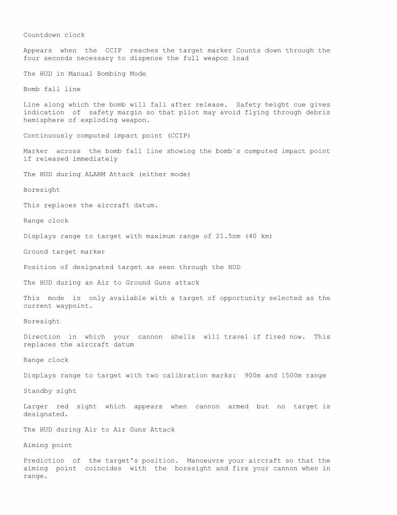
Countdown clock
Appears when the CCIP reaches the target marker Counts down through the
four seconds necessary to dispense the full weapon load
The HUD in Manual Bombing Mode
Bomb fall line
Line along which the bomb will fall after release. Safety height cue gives
indication of safety margin so that pilot may avoid flying through debris
hemisphere of exploding weapon.
Continuously computed impact point (CCIP)
Marker across the bomb fall line showing the bomb`s computed impact point
if released immediately
The HUD during ALARM Attack (either mode)
Boresight
This replaces the aircraft datum.
Range clock
Displays range to target with maximum range of 21.5nm (40 km)
Ground target marker
Position of designated target as seen through the HUD
The HUD during an Air to Ground Guns attack
This mode is only available with a target of opportunity selected as the
current waypoint.
Boresight
Direction in which your cannon shells will travel if fired now. This
replaces the aircraft datum
Range clock
Displays range to target with two calibration marks: 900m and 1500m range
Standby sight
Larger red sight which appears when cannon armed but no target is
designated.
The HUD during Air to Air Guns Attack
Aiming point
Prediction of the target's position. Manoeuvre your aircraft so that the
aiming point coincides with the boresight and fire your cannon when in
range.

Air target marker
Position of air target projected onto HUD display.
Range clock
Displays range to target with two calibration marks: 400m and 600m range
The HUD in AIM9 mode - no IR acquisition yet
IR Lock diamond
When the missile`s l seeker has acquired the target this symbol moves from
the centre of the HUD to the target marker.
Range clock
Shows range to target, calibrated for AIM L
Aiming point
Prediction of the targets position. May be used as a steering cue.
The HUD in SKY FLASH mode (ADV only)
Mode is similar to AIM9L symbology but without the IR lock diamond
Navigator / Weapons Officers Seat
Views available
This is the view looking forward from the navigator`s position (rear
cockpit). The entire screen is occupied by the instrument panel, the view
forwards being totally obscured by the large TV TA displays and the back of
the pilots ejection seat. The navigator may however select a forward
camera view on either TAB display or the MFD. Panel illumination
self-adjusts with time of day and red or green cockpit lighting is
selectable at night
Look left from the navigator`s position by pressing the Look Left key.
Releasing the key will return to the forward view. If you wish to continue
looking left, either hold down the key or press Shift and Look Left to lock
the view. There are no cockpit instruments on this side view.
Look right from the navigator`s position by pressing the Look Right key.
Releasing the key will return to the forward view. If you wish to continue
looking right, either hold down the key or press Shift and Look Right to
lock the view. There are no cockpit instruments on this side view.
---------------------------------------------------------------------------
5 6
14 17
7
1 8 13
9 10 11 12

2
3
18
15 16
4
____________________________________________________________________________
NAVIGATORS INSTRUMENT PANEL
Items common with front cockpit
1 Mouse active indicator
2 Landing gear position indicator
3 Attitude direction indicator
4 Horizontal situation indicator
5 Altimeter
6 Indicated airspeed / Mach number
7 Multi function display
8 Mouse active indicator
9 Autopilot engaged indicator
10 Autothrottle engaged indicator
11 Radar "on" indicator
12 ECM "on" indicator
13 Mouse active indicator
Items unique to rear cockpit
14 Left TV TAB display
15 Analogue clock
16 Stores management display
17 Right TV TAB display
18 Central warning panel
TV TAB displays
Use the Left or Right "TAB Function Select" key to cycle through the
following on either display. n b. the displays are mutually exclusive.
(a) Forward looking camera
Provides a daytime forward view and an image-intensified nightime forward
view for the navigator.
(b) Scrollable Map
Moving map display used for setting waypoints for targets of opportunity
(c) Thermal Imaging and Laser Designation system (TIALD)
Used to pinpoint targets with laser beam from medium altitude,
(d) Flight Plan display (PLN)
Shows aircraft position relative to flightplan.
(e) Local map
Zoomable moving map display showing current aircraft position
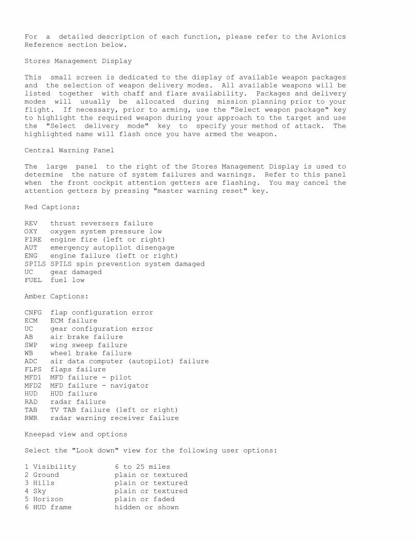
For a detailed description of each function, please refer to the Avionics
Reference section below.
Stores Management Display
This small screen is dedicated to the display of available weapon packages
and the selection of weapon delivery modes. All available weapons will be
listed together with chaff and flare availability. Packages and delivery
modes will usually be allocated during mission planning prior to your
flight. If necessary, prior to arming, use the "Select weapon package" key
to highlight the required weapon during your approach to the target and use
the "Select delivery mode" key to specify your method of attack. The
highlighted name will flash once you have armed the weapon.
Central Warning Panel
The large panel to the right of the Stores Management Display is used to
determine the nature of system failures and warnings. Refer to this panel
when the front cockpit attention getters are flashing. You may cancel the
attention getters by pressing "master warning reset" key.
Red Captions:
REV thrust reversers failure
OXY oxygen system pressure low
FIRE engine fire (left or right)
AUT emergency autopilot disengage
ENG engine failure (left or right)
SPILS SPILS spin prevention system damaged
UC gear damaged
FUEL fuel low
Amber Captions:
CNFG flap configuration error
ECM ECM failure
UC gear configuration error
AB air brake failure
SWP wing sweep failure
WB wheel brake failure
ADC air data computer (autopilot) failure
FLPS flaps failure
MFD1 MFD failure - pilot
MFD2 MFD failure - navigator
HUD HUD failure
RAD radar failure
TAB TV TAB failure (left or right)
RWR radar warning receiver failure
Kneepad view and options
Select the "Look down" view for the following user options:
1 Visibility 6 to 25 miles
2 Ground plain or textured
3 Hills plain or textured
4 Sky plain or textured
5 Horizon plain or faded
6 HUD frame hidden or shown

7 Control device keyboard 1 or 2
joystick 1 or 2
8 Sound effects off or on
0 Minimise / restore
Options 1 to 6 adjust aspects of "Tornado" that will affect the smoothness
with which it runs on your computer. For example, reducing the visibility
will mean that ground objects cannot be seen until you get closer to them.
Less ground detail on the screen will give a smoother simulation on slower
computers Selecting the "plain" options in 2 to 5 will also improve
performance on a slow computer.
Option 7 allows you to select different primary flight controls:
(i) keyboard 1 roll rate and pitch rate proportional to how long key is
depressed Roll and pitch rates reduce to zero when key released
(ii) keyboard 2 roll rate and pitch rate proportional to how long key is
depressed. Roll and pitch rates maintained when key released.
(iii) joystick 1 single joystick option. Joystick provides pitch and roll
control
(iv) joystick 2 two joystick option. Joystick 1 provides pitch and roll
control Joystick 2 provides throttle and rudder control.
Option 0 - Reduces Visibility to 6 miles and selects "plain" for options 2
to 5 with single keystroke. This option offers instant frame rate boost -
useful in combat. To restore your previous setting hit 0 again.
AVIONICS REFERENCE
Multi Function Display (MFD)
Mounted centrally on the instrument panel of both pilot and navigator you
will see the Multi Function Display, a distinguishing feature of the GR4
Tornado This unit offers a varIety of functions, selected by the "Centre
MFD Function Select" key:
(a) Autopilot and Flight Director System (AFDS) and Autothrottle settings
- if active
(b) Local map
(c) ILS
(d) Radar - if active
(e) Forward looking camera
(a) Autopilot Flight Director System (AFDS) and Autothrottle
Depending upon the mode selected, the autopilot will take control of your
altitude (ALT), your heading (HDG) and your Indicated Air Speed (IAS).
Five autopilot modes are available:
(i) Track
(ii) Altitude/Heading Acquire
(iii) Terrain Follow
(iv) Approach
(v) Autothrottle
(i) Track (AFDS TRACK (-) ) this mode will command the aircraft to follow a
flight plan defined during your pre flight briefing or to fly to a waypoint
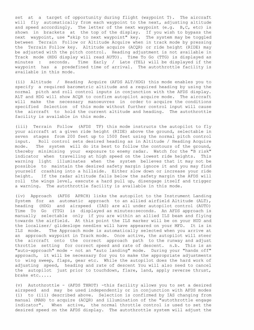
set at a target of opportunity during flight (waypoint T). The aircraft
will fly automatically from each waypoint to the next, adjusting altitude
and speed accordingly. The letter of the next waypoint (e.g. B,C, etc) is
shown in brackets at the top of the display. If you wish to bypass the
next waypoint, use "skip to next waypoint" key. The system may be toggled
between Terrain Follow or Altitude Acquire when in track mode by pressing
the Terrain Follow key. Altitude acquire (ACQR) or ride height (RIDE) may
be adjusted with the pitch control. Heading adjustment is not available in
Track mode (HDG display will read AUTO). Time To Go (TTG) is displayed as
minutes : seconds. Time Early / Late (TEL) will be displayed if the
waypoint has a predefined time of arrival. The autothrottle facility is
available in this mode.
(ii) Altitude / Heading Acquire (AFDS ALT/HDG) this mode enables you to
specify a required barometric altitude and a required heading by using the
normal pitch and roll control inputs in conjunction with the AFDS display.
ALT and HDG will show ACQR to confirm autopilot acquire mode. The aircraft
will make the necessary manoeuvres in order to acquire the conditions
specified Selection of this mode without further control input will cause
the aircraft to hold the current altitude and heading. The autothrottle
facility is available in this mode.
(iii) Terrain Follow (AFDS TF) this mode instructs the autopilot to fly
your aircraft at a given ride height (RIDE) above the ground, selectable in
seven stages from 200 feet up to 1500 feet using the normal pitch control
input. Roll control sets desired heading as in Altitude / Heading Acquire
mode. The system will do its best to follow the contours of the ground,
thereby minimising your exposure to enemy radar. Watch for the "B risk"
indicator when travelling at high speed on the lowest ride heights. This
warning light illuminates when the system believes that it may not be
possible to maintain the desired safety margin ignore it and you may find
yourself crashing into a hillside. Either slow down or increase your ride
height. If the radar altitude falls below the safety margin the AFDS will
roll the wings level, execute a hard pull up, disengage itself and trigger
a warning. The autothrottle facility is available in this mode.
(iv) Approach (AFDS APRCH) links the autopilot to the Instrument Landing
System for an automatic approach to an allied airfield Altitude (ALT),
heading (HDG) and airspeed (IAS) are all under autopilot control (AUTO)
Time To Go (TTG) is displayed as minutes:seconds. An AFDS approach is
manually selectable only if you are within an allied ILS beam and flying
towards the airfield. At this point the ILS marker will be on your HUD and
the localiser/ glideslope needles will have appeared on your MFD. It is in
ILS mode. The Approach mode is automatically selected when you arrive at
an approach waypoint in Track mode. Once active, the autopilot will steer
the aircraft onto the correct approach path to the runway and adjust
throttle setting for correct speed and rate of descent. n.b. This is an
"auto-approach" mode - not an "auto landing" mode. During your "hands off"
approach, it will be necessary for you to make the appropriate adjustments
to wing sweep, flaps, gear etc. While the autopilot does the hard work of
adjusting speed, heading and rate of descent You will also need to cancel
the autopilot just prior to touchdown, flare, land, apply reverse thrust,
brake etc.....
(v) Autothrottle - (AFDS THROT) -this facility allows you to set a desired
airspeed and may be used independently or in conjunction with AFDS modes
(i) to (iii) described above. Selection is confirmed by IAS changing from
manual (MAN) to acquire (ACQR) and illumination of the "autothrottle engage
indicator". When active, the normal throttle control is used to set the
desired speed on the AFDS display. The autothrottle system will adjust the

engine thrust accordingly in an attempt to maintain the demanded speed.
However, please note that this is not possible in all circumstances e.g.
in a steep climb or dive or high "g" turn.
Finally, if you disengage the autopilot, pitch and roll control revert to
manual (MAN) and the MFD will confirm AFDS OFF if autothrottle is not
active, or AFDS THROT if autothrottle is active.
(b) Local Map
This is a moving map display orientated about your present position. The
display shows hills, roads, rivers, airfields (active runway in white) and
waypoints (B,C,D etc). The map origin may be toggled between the centre of
the display or at the base of the display. Your aircraft is always at the
map origin, heading along the dotted flightpath. The scale of the map is
selectable (i.e zoom in and out) from 0.5nm. 1nm, 2nm, 4nm, 8nm and 16 nm
with a base origin.
(c) Instrument Landing System (ILS)
Select this display during your final approach to see the ILS localiser and
glideslope indicators. Additional information on this screen includes
aircraft leading (top left corner), bearing to the runway mid-point (top
right corner), estimated time to touchdown (lower left corner) and distance
to runway mid - point (lower right corner).
(d) Radar
The radar has two independent modes of operation, each with on / off
control. If the desired radar mode does not appear as you cycle through
the MFD functions, first check that the radar is switched on.
(i) air mode used for detecting, designating and tracking aircraft. The
air radar is a plan view display showing target range and bearing only.
Both enemy and allied aircraft are shown, differentiated by symbology. Use
your mouse to move the designator symbol to coincide with the chosen target
and designate with the left mouse button. Designation may be cancelled
with the right mouse button. If the designator does not appear to respond
to the mouse check that the MFD is the active display for the mouse by
pressing the Tab key.
The ADV air radar has three selectable ranges: 30 nm (for use with Sky
Flash) 10 nm (for use with AIM9L) and 2 miles (for use with guns). The IDS
radar has only the 10 nm and 2nm range settings. It is also possible to
lock on to a target visually through the HUD by using the boresight
designate key. Please note that use of the radar at very low altitudes
will be affected by terrain masking ie. it cannot see through hills!
(ii) ground mode - used primarily for detecting, designating and tracking
military ground vehicles. The display is a composite image of radar
returns and digital map data which are compared to identify and highlight
vehicles. Due to terrain masking, vehicle returns may be intermittent
whereas mapped features will always be shown. Use your mouse to move the
designator symbol to coincide with the chosen target position and designate
with the left mouse button. Designation may be cancelled with the right
mouse button. If the designator does not appear to respond to the mouse,
check that the MFD is the active display for the mouse by pressing the Tab
key.
The IDS radar has six selectable ranges: 0.5nm, 1nm, 2nm, 4nm, 8nm and

16nm. The ADV is not fitted with a ground radar.
(e) Forward looking camera
This display provides a daytime forward view for the navigator and an
image- intensified view for both crew at night.
TV TAB displays (navigator's cockpit)
Both left and right TV TAB displays offer a variety of functions on a
mutually exclusive basis. Items such as Forward Looking Camera and local
map are also available on the central MFD Functions are selected by
repeatedly pressing the Left (or Right) Tab Function Select key:
(a) Flight Plan Display (PLN)
(b) Thermal Imaging and Laser Designating (TIALD)
(c) Scrollable map
(d) Local map
(e) Forward looking camera
It is also possible to switch off each TV Tab display.
(a) Flight Plan Display (PLN)
Normally displayed on the left hand TV TAB, this option shows your aircraft
position relative to your flight plan. All pre-planned waypoints are shown
(A,B,C etc) plus any target of opportunity waypoint (T) set during flight.
The scale of the display adjusts automatically in order to keep both your
current position (small circle) and your pre-planned flight path on the
display simultaneously Also appearing on the Flight Plan Display are
aircraft heading (top left corner) bearing of next waypoint (top right
corner), estimated time to next waypoint (lower left corner) and distance
to the next waypoint (lower right corner). nb The estimated time will only
be displayed if you are heading in the general direction of the next
waypoint, otherwise calculation would be impossible.
(b) Thermal Imaging and Laser Designating (TIALD)
This is a steerable plan view camera with laser designator. It is capable
of looking ahead, behind and to the sides of your aircraft. Its range
increases with altitude and ideally it would be used at above 20,000 feet.
In order to give the widest field of view. Camera steering and target
designation is by means of the mouse. As the camera looks ahead of your
aircraft, the designator symbol changes to confirm this fact. It is
recommended that you designate targets ahead of your aircraft in order to
give the laser-guided bombs sufficient time to reach their targets. A
continuous zoom facility allows pin-point accuracy Prior to take-off this
equipment does not function and the TV Tab will display. a large cross
(c) Scrollable map
This is a slewable map on which the navigator may designate and select a
target of opportunity waypoint (waypoint T). Map scale is selectable from
0.75nm up to 24nm. Unlike the Local map where your aircraft is fixed at
the centre or bottom cemtre the display, on the scrollable map your air
craft symbol scrolls with the map and may leave the display altogether.
Pressing the "locate aircraft" key will centre the map at your current
position if you are within the boundaries of the map. Pressing the "locate
target" key will centre the map at the position of waypoint T ie set
Additional navigational data is presented in each corner:

Upper left: aircraft heading
Upper right: bearing to position of cursor
Lower left: estimated time to reach position of cursor
Lower right: distance in n.m. to position of cursor
nb If you are flying away from the cursor position, it is not possible to
display an estimated time.
(d) Local map
This is very similar to the Local Map mode of the MFD but with selectable
ranges from 0.75nm, 1.5nm, 3nm, 6nm, 12nm and 24nm with the base origin.
(e) Forward looking camera
This display provides a daytime forward view for the navigator and an
image-intensified nightime forward view for the navigator.
Full-Screen Moving Map
A full screen moving map display is available with zoom controls. The
boundaries of the combat zone are not shown. The map is always centred at
your present point and orientated so that you are flying directly up the
screen Please note that the simulation continues in real time when this map
is displayed. For safety reasons we recommend that you select autopilot
before switching to the map.
USEFUL CHECKLISTS
Takeoff checks
Wheelbrakes on
25° wing sweep
Mid flap setting
Throttle OPEN Reheat ON FULL
Wheelbrakes off (at 100% rpm and max. reheat)
Pull back when speed above 140 knots
Do not rotate beyond 15° nose up
Gear UP after take off
Maintain climb angle of between 10° and 20° (1st and 2nd pitch bars on HUD)
Flaps Up when speed above 215 knots
Select 45° wing sweep above 350 knots
Landing checks
25° wing sweep
Full flap setting
Gear down
Airspeed approx 150 kts (no external stores, 25% internal fuel)
Descent rate at touchdown: max. 20 ft/s at min.weight
max. 4 ft/sec at max weight
Engage reverse thrust after touchdown
Open throttle to 100%
Monitor speed
Throttle to idle at 80kts
Disengage reverse thrust
Apply wheelbrakes
n.b Minimum speed with reverse thrust engaged is 50 to 70kts (reheat must
not be used)

Limiting speeds
Vmax sea level Mach 1.2+
Vmax 36000 ft Mach 2.2
Vmax for each wing sweep
at 25° sweep: Mach 0.73
at 45° sweep: Mach 0.88
at 67° sweep: Mach 2.20
Vmax manoeuvre flaps 450 kts IAS
Vmax mid flaps 280 kts IAS
Vmax full flaps 225 kts IAS
Vmax ulc down 350 kts (warning at 250kts)
The following speeds will vary with aircraft weight:
Vstall 25° sweep (power off) 135 kts (zero flaps)
Vstall 25o sweep (power off) 120 kts (mid flaps)
Vstall 25o sweep (power off) 108 kts (full flaps)
Vstall 45° sweep 155 kts (zero flaps)
Vstall 67° sweep 182kts
max positive g 7.5
max negative g -3
max roll rate 180o/sec
Approach & landing emergencies:
Landing with wings swept or flap failure:
1. Jettison all stores
2. See table below for approach speed
After touchdown:
3. Throttle to idle
4. Lower nosewheel
5. Engage thrust reverse
6. Throttle to 80%
7. Throttle to 100% at 130 kts
8. Throttle to idle at 85 kts
9. Apply wheelbrakes
wing flaps speed AoA
sweep
25 up 180 12 add 7kt per 1000 kg above 15000 kg
mid 164 9
45 up 199 13 add 5kt per 1000 kg above 15000 kg
67 up 208 16
Spin recovery procedure:
1. Select 25 sweep
2. Identify direction of rotation
3. Stick back
4. Pro spin aileron i.e. push stick in direction of rotation
5. Hold until spin stops
6. Centralise stick

7. Open throttle
REFERENCE
---------
Tornado GR4
Category: two seat all-weather multi purpose combat aircraft
Origin: United Kingdom
Wing span: fully spread: 45ft 7.5in (13.91m)
fully swept: 28ft 2.5in (8.6m)
Length: 54ft 10in (16.72m)
Height: 19ft 6in (5.95m)
Maximum weapon load: 198401b (9000kg)
Max level flight at altitude clean M2.2
Max. level speed sea level clean M1.2
Radius of action 750nm
g limit +7.5
Tornado F3
Category: two seat all weather air defence interceptor
Origin: United Kingdom
Wing Span: fully spread: 45ft 7.5in (13.91m)
fully swept: 28ft 2.5in (8.6m)
Length: 61ft 3in (18.68m)
Height: 19ft 6in (5.95m)
Weight,empty 319701b (14500kg)
Maximum weapon load: 187401b (8500 kg)
Max. Level flight at altitude clean M2.2
Max. Level speed at sea level clean M1.2
Radius of action 1000nm
g limit +7.5
F-15 Eagte
Category: single-seat air superiority fighter
Origin: USA
WingSpan: 42ft 10in (13.05m)
Length: 63ft 9in (19.43m)
Height: 18ft 5.5in (5.63m)
Weight: 31700lb (14379kg)
Max. weapon load: 24500lb (11113kg)
Max. level flight at altitude clean M2.5
Radius of action 685nm
g limit +7.3
F-16C Fighting Falcon
Category: single-seat multi role fighter
Origin: USA
Wing span: 31 ft 0in (9.45m)
Length: 47ft 8in (14.52m)
Height: 16ft 5in (5.01m)
Weight empty: 18238lb (8273kg)
Max. weapon load: 12000lb (5443kg)
Max. level flight at altitude clean M2.5
Radius of action 500+nm
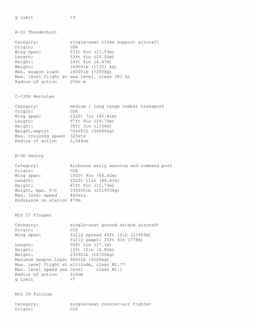
g limit +9
A-1O Thunderbolt
Category: single-seat close support aircraft
Origin: USA
Wing Span: 57ft 6in (17.53m)
Length: 53ft 4in (16.26m)
Height: 14ft 8in (4.47m)
Weight: 24959lb (11321 kg)
Max. weapon load: 16000lb (7250kg)
Max. level flight at sea level. clean 381 kt
Radius of action 250n m
C-130H Hercules
Category: medium / long range combat transport
Origin: USA
Wing span: 132ft 7in (40.41m)
Length: 97ft 9in (29.79m)
Height: 38ft 3in (1166m)
Weight,empty: 76469lb (34686kg)
Max. cruising speed 325kts
Radius of action 2,046nm
E-3D Sentry
Category: Airborne early warning and command post
Origin: USA
Wing span: 145ft 9in (44.42m)
Length: 152ft 11in (46.61m)
Height: 41ft 9in (12.73m)
Weight, max. T-O 335000lb (151953kg)
Max. level speed 460kts
Endurance on station 870m
MiG 27 Flogger
Category: single-seat ground attack aircraft
Origin: CIS
Wing span: fully spread 45ft 10in (13965m)
fully swept: 25ft 6in (778m)
Length: 56ft 1in (17.1m)
Height: 15ft 10in (4.82m)
Weight: 23590lb (10700kg)
Maximum weapon load: 9920lb (4500kg)
Max. level flight at altitude, clean M1.77
Max. level speed sea level clean M1.1
Radius of action 210nm
g limit +7
MiG 29 Fulcrum
Category: single-seat counter-air fighter
Origin: CIS
Wing span: 37ft 3in (11.36m)
Length: 56ft 10in (17.32m)
Height: 15ft 6in (4.73m)
Max. T-O weight: 39700lb (18000kg)
Max level flight at altitude clean M2.3
Max. level speed sea level clean M1.06
Radius of action 600nm
g limit +9
MiG 31 Foxhound
Category: two-seat all-weather interceptor
Origin: CIS
Wing span: 45ft 11in (14.0m)
Length: 70ft 6.5in (21.5m)
Height: 18ft 4in (5.6m)
Weight, empty: 48115lb (21825kg)
Maximum T-O weight: 90725lb (41150kg)
Max. level flight at altitude clean M2.4
Max. level speed sea level clean M1.1
Radlus of action 1135nm
limit +5
Su-25 Frogfoot
Category: single-seat close support aircraft
Origin: CIS
Wing span: 47ft 1.5in (14.36m)
Length: 50ft 11.5in (15.53m)
Height: 15ft 9in (4.8m)
Max T-O weight, 20950lb (9500kg)
Max level speed sea level, clean M0.8
Radius of action 405n m
g limit +6.5
Su-27 Flanker single-seat counter air fighter
Category: single seat counter air fighter
Origin: CIS
WingSpan: 48ft 3in (14.7m)
Length: 71ft 11.5in (14.7m)
Height: 19ft 5.5in (5.93m)
Weight: 49600lb (22500kg)
Max. level flight at altitude clean M2.35
Max. level speed sea level clean M1.1
Radius of action 810nm
limit +9
Il-76 Candid
Category: medium / long range combat transport
Origin: CIS
Wing span: 165ft 8in (50.5m)
Length: 152ft 10in (45.59m)
Height: 48ft 5in (1476m)
Max T O weight, 418875lb (190000kg)

Max. level speed sea level, clean 459kts
Radius of action 2700nm
A-50 Mainstay
Category: airborne early warning
Origin: CIS
Wing span: 165ft 8in (50.5m)
Length: 152ft 10in (45.59m)
Weight: 48ft 5in (14.76m)
Max T-O weight. 418875lb (190000kg)
Max level speed sea level, clean 459kts
Radius of action 2700nm
AH-64 Apache helicopter gunship
Category: helicopter gunship
Origin: USA
Main rotor diameter: 48ft 0in (14.63m)
Length: 58ft 3in (17.76m)
Height: 15ft 3in (4.66m)
Max T-O weight, 21000lb (9525kg)
Max. level speed sea level 160kts
Radius of action 260nm
g limit +3.5
Mi-24 Hind
Category: helicopter gunship
Origin: CIS
Main rotor diameter: 56ft 9in (17.3m)
Length: 70ft 6in (21.5m)
Height: 21ft 4in (6.5m)
Normal T O weight 26455lb (12000kg)
Max. level speed sea level 172kts
Radius of action 86nm
CH-47 Chinook
Category: medium transport helicopter
Origin: USA
Main rotor diameter: 60ft 0in (18.29m)
Length: 98ft 11in (30.14m)
Height. 18ft 8in (5.68m)
Max T O weight 54000lb (24494kg)
Max. level speed sea level 163kts
Radius of action 100nm
Mi-26 Halo
Category: heavy transport helicopter
Origin: CIS
Main rotor diameter: 105ft 0in (32.0m)
Length: 131 ft 4in (40.0m)
Height: 26ft 9in (8.1 m)

Max. T O weight 123450lb (56113kg)
Max level speed sea level 159kts
Radius of action 432nm
AIR DEFENCE SYSTEMS
Patriot
Category: mobile surface-to-air missile system
Origin: USA
Length: 17ft 5in (5.31m)
Diameter: 16in (0.406m)
Wingspan: 3ft (0.92m)
Warhead: 221 lb (100kg)
HE fragmentation with proximity fuse
Weight: 2195lb (998kg)
Performance: speed: Mach 3
range: 42nm (68km)
ZSU-23-4 Shilka
Category: mobile anti aircraft artillery system
Origin: CIS
Length: 21ft 6in (6.54m)
Width: 9ft 8in (2.95m)
Height: 12ft 6in (3.8m)
Armament: four 23mm cannon
range: 1750yds (2500m)
Weight: 45194lb (20500kg)
Performance: speed: 27mph (44km/h)
range: 280nm (450km)
ZRK ROMB (SA-8)
Category: amphibious mobile surface-to-air missile system
Origin: CIS
Length: 30ft 0in (9.14m)
Width: 9ft 6in (2.9m)
Height: 13ft 9in (4.2m)
Armament: six SA-8 Gecko missiles
Effective range: 7.5nm (12000m)
Altitude limits: (5000m)
Weight: 198411b (9000kg)
Performance: speed: 37 mph (60km/h)
GROUND FORCES
Challenger
Origin: United Kingdom
Length: 37ft 11in (11.56m)
Width: 11ft 6in (3.52m)
Height: 9ft 8in (2.95m)
Armament: one 120mm gun
one 7.62mm machine gun, coaxial
one 7.62mm machine gun, anti aircraft
Weight: 1366851b (62000kg)
Performance: speed: 35mph (56km/h)
range: 373nm (600km)
T-80
Origin: CIS
Length: 32ft 6in (9.9m)
Width: 11ft 2in (3.4m)
Height: 7ft 3in (2.2m)
Armament: One 125mm gun
One 7.62mm machine gun,coaxial
One 12.7mm machine gun, anti aircraft
Weight: 94798lb (43000kg)
Performance: speed: 46mph (75km/h)
range: 248nm (400km)
Warrior
Origin: United Kingdom
Length: 20ft 10in (6.34m)
Width: 9ft 11in (3.03m)
Height: 9ft 0in (2.73m)
Armament: One 30mm RARDEN cannon
One 7.62mm machine gun, coaxial
Weight: 49603lb (22500kg)
Performance: speed: 46mph (75km/h)
range: 310nm (500km)
BMP-2
Origin: CIS
Length: 22ft 0in (6.71 m)
Width: 10ft 2in (3.09m)
Height: 6ft 9in (2.06m)
Armament: One 30mm cannon
One 7.62mm machine gun, coaxial
One launcher for AT-5 Spandrel anti-tank missiles
Weight: 32187lb (14600kg)
Performance: speed: 40mph (65km/h)
range: 373nm (600km)
MLRS
Category: surface-to-surface battlefield missile launcher
Origin: USA
Length of rocket: 12ft 11in (3.94m)
Diameter: 8.66in (0.22m)
Weight: 675lb (307kg)
Performance: range: 20nm
MAZ 543 and SS-1 SCUD
SS 1 SCUD
Category: surface-to surface battlefield missile
Origin: CIS

Length: 37ft 5in (11.4m)
Dianmeter: 2ft 9in (0.84m)
Weight: 140431b (6370kg)
Performance: range: 50 to 174nm
WEAPON DATA
The following data has been compiled from manufacturers information and
actual performance may differ considerably. The effective range of all
missiles decreases significantly when used at low altitude.
AIM9-L Sidewinder
Origin: USA
Guidance system: all aspect infra red
Length: 9ft 4in (2.85m)
Diameter: 5in (127mm)
Weight: 188lb (853kg)
Warhead: 25lb (11.4kg)
Performance: annular blast tragmentation
speed: Mach 2.5
range: 11nm (17.7km)
Active Sky Flash
Origin: United Kingdom
Guidance system: all aspect active radar
Length: 12ft 1in (368m)
Diameter: 8in (0.2m)
Span: 3ft 4in (1.02m)
Weight: 425lb (193kg)
Warhead: 66lb (29.9kg) proximity and impact delay fused
blast fragmentation
Performance speed: Mach 4
range: 31nm (50km)
AA-2-2C Advanced Atoll
Origin: CIS
Guidance system: rear-aspect intra red
Length: 9ft 2in (2.8m)
Diameter: 4.7in (0.12m)
Span: 1ft 9in (0.53m)
Weight: 154lb (70kg)
Warhead: 13lb (6kg) impact delay fused blast fragmentation
Performance: speed: Mach 2.5
range: 5nm (8km)
AA-7B Apex
Origin: CIS
Guidance system: semi active active radar
Length: 15ft 1in (4.6m)
Diameter: 8.8in (0.223m)
Span: 3ft 5in (1.05m)
Weight: 7051b (320kg)
Warhead: 881b (40kg) proximity and impact-fused blast fragmentation

Performance: speed: Mach 3.5
range: 34nm (55km)
AA-8A/B Aphid
Origin: CIS
Guidance system: infra-red (AA-8A) or semi active radar homing (AA 8B)
Length: AA-8A 7ft 0in (2.15m)
AA-8B 7ft 8in (2.35m)
Diameter: 4.7in (0.12m)
Span: 1ft 3in (0.4m)
Weight: AA-8A 121lb (55kg)
AA-8B 132lb (60kg)
Warhead: proximity and impact fuzed blast fragmentation
Performance: speed: Mach 3
range: AA-8A 6nm (10km)
AA-8B 9nm (15km)
AA-1O Alamo
Origin: CIS
Guidance system: infra red or semi-active radar homing
Length radar variant 13ft 1in (4Om)
IR variant 10ft 6in (32m)
Diameter: 7.3in (0.185m)
Span: 2ft 9in (0.855m)
Weight: radar variant 440lb (200kg)
IR variant 342lb (155kg)
Warhead: blast fragmentation
Performance: speed: Mach 3
range: radar variant 24nm (40km)
IR variant 12nm (20km)
BAe/ Marconi ALARM
Origin: United Kingdom
Category: air-to-surface anti-radiation tactical missile
Guidance system: passive radar seeking
Length: 13ft 11in (4.242m)
Diameter: 8.7in (0.22m)
Span: 2ft 4in (0.72m)
Weight: 385lb (175kg)
Warhead: laser proximity-fused MBB HE
Performance: speed: classified
range: classified
JP 233
Origin: United Kingdom
Category: heavy-weight airfield attack and area denial
submunition dispense
Guidance system: computer-controlled weapon release
Length: 21ft 6in (6.55m)
Width: 2ft 9in (0.84m)
Height: 1ft 11in (0.6m)
Weight: 5148lb (2335kg) per dispenser (Tornado carries 2)
Warhead: 3O SG357 concrete penetrating and 215 HB876 area
denial submunitions
BL755
Origin: United Kingdom
Category: medium-weight cluster bomb
Method of release: lay down or manual
Length: 8ft 0in (2.45m)
Diameter: 1ft 4in (0.42m)
Span: 1ft 10in (0.56m)
Weight: 582lb (264kg)
Warhead: 147 antitank / fragmentation bomblets
1000lb freefall bomb
Origin: United Kingdom
Ævailable in three varieties:
(a) general purpose (GPB)
(b) retarded (RET)
(c) laser-guided (LGB)
Method of release:
(a) GPB - manual, loft or lay down
(b) RET manual or lay down
(c) LGB - manual, loft, lay down
or using TIALD
GLOSSARY AND ABBREVIATIONS
AA threats anti-aircraft threats e.g. AAA and SAM sites
AAA anti-aircraft artillery
AAM air-to-air missile
ACM air combat manoeuvering
ACQR acquire through autopilot
ADI attitude direction indicator
ADV air defence variant of Tornado
AFDS autopilot and flight director system
AFV armoured fighting vehicle
AHA altitude/heading acquire mode of autopilot
AIM9-L heat-seeking air to air missile
ALARM air launched anti-radiation missile
Alpha see angle of attack
ALT altitude
Analogue joystick with output proportional to its displacement
Angle of attack angle between wing and direction of airflow
Approach point start of approach to an airfield
APRCH approach
AUTO under total autopilot control
Autothrottle system used to set a demanded airspeed
Autotrim computer-assisted turn coordination
AGM air-to-ground missile
AOA angle of attack
AWACS airborne warning and control system
B risk terrain following system safety margin error warning
Bearing heading required to fly towards target or waypoint
Blackout loss of consciousness due to pulling g
BL755 cluster bomb
BVR beyond visual range
C3 command, control and communications
CAP combat air patrol
CAS close air support
CCIP continuously computed impact point
Chaff tiny foil strips used to decoy radar-guided missiles
ClS Confederation of Independant States
Combat power maximum reheat setting
Dead stick flight with zero engine thrust
deg degree
Digital joystk joystick capable only of on/off output
DlR direct - ALARM mode
ECM electronic countermeasures
Egress flying out of the target area
EWR early warning radar
Flaps trailng edge aerofoils on each wing
Flares used to decoy heat-seeking missiles
g or G weight multiplying factor, units of gravity
Glideslope descent rate reference of ILS system
G-LOC gravity-induced loss of consciousness
GPB general purpose bomb
Groundspeed actual speed over the ground
HAS hardened aircraft shelter
HDG heading
Heading strip symbols on HUD showing aircraft heading
HUD head up display
IAS indicated airspeed
IDS interdictor strike variant of Tornado
IND Indirect - ALARM mode
ILS Instrument landing system
Initial point turning point from which you start your attack run
Jettison to reduce aircraft weight in an emergency
JP.233 runway denial weapon
KIA killed In action
KlT killed in training
kts knots, nautical miles per hour
LAY laydown attack
LFT loft attack
LGB laser-guided bomb
Lift vector force generated by air flowing over the wings
Localiser left/right reference of ILS system
Mach number aircraft speed expressed as a fraction or multiple of the
local speed of sound
MAN manual control or manual attack
MFD multi function display
MTOW maximum takeoff weight
n.m. nautical mile
NLT not later than
OCU operational conversion unit
package group of weapons designated for use against particular
target
Pitch bars lines drawn on HUD showing aircraft pitch and roll
PLN flight plan tab display
POL petrol, oil and lubricants
POW prisoner of war
RAF Royal Air Force
Redout loss of consciousness due to negative g
RET retarded bomb
Ride height altitude seting selected when using terrain following
engine revolutions per minute, corresponds to thrust
if reheat not selected
RWR radar warning receiver

SAM surface to air missile
SARH semi active radar homing
Sec second
SKYF HUD symbol for Sky Flash missile
Sky Flash radar-guided air-to-air missile
Slats leading edge aerofoils
SMD stores management display
SPILS spin prevention and incidence limiting system
Spin stalled descent along a steep helical path
Stall loss of control due to wings no longer generating lift
Tab Multi purpose displays in rear cockpit
TAS true airspeed
Tasking order mission description
TEL time early/late
TF terrain following
TFR terrain following radar
THROT autothrottle
Thrust reversers devices used to achieve a braking effect
TfALD thermal imaging and laser designating system
ToO target of opportunity
TOT time on target
Training area flying area used in simulator or flying training
TRN terrain referenced navigation
True airspeed speed relative to the air through which you are
flying
TTG time to go
TV TAB large multi purpose displays in the rear cockpit
TWCU Tornado Weapons Conversion Unit
Unloading pushing the stick to reduce aerodynamic drag
VSI vertical speed indicator
Warzone combat flying area - choice of 3
Waypoint position stored by the navigation system
Project manager - David Marshall
Design team - Kevin Bezant, Nick Mascall, Tony Hosier, Robin Heydon
Mathew Smith
Manual writing - Nick Mascall, David Marshall
Manual layout, graphics, artwork and package design - Kerry Le-Gray
Wendy Hoskin
Technical illustrations - Derrol Euling
Beta testing - Rod Swift, Russell Alcock, Jeffrey Love
Production - Rod Cobain, Stephanie Burnett
Marketing - Debbie Durrant
Ancillary support - Vicki McBurnie, Julie-Ann Merrit, Gill Niland
Sound Effects - David Whittaker
Music - David Punshon, Sound Images
Acknowledgements

Royal Air Force video and photograhic material
British Aerospace Warton video and photograhic material, sound effects
and for permission to use the Tornado logo
Royal Aeronautical Society research and technical reports
Janes Information Systems photographic material
GKN Defence technical illustration of Warrior APC
Julian Savarin (ex-RAF) technical information
Spectrum HoloByte for their help in the final stages of the
development. It has been a pleasure to work
with a publisher as committed as ourselves
to producing quality flight simulators.
Our special thanks to RAF Honington, the pilots and navigators of XIII and
XV squadrons, technicians, air traffic control, the Community Relations
Officer and in particular the Flight Simulator Group. Their assistance and
enthusiasm during this project was invaluable
Suggested reading
Panavia Tornado Dr. Alfred Price
Fighter Combat Robert L Shaw
The Ace Factor Mike Spick
---
Typed by SHaRD/N&B
For more Amiga documents, visit www.lemonamiga.com