Embed Size (px)
Citation preview

CHAPTER 1. BEFORE SERVICING
CHAPTER 2. WARNING TO SERVICE PERSONNEL
CHAPTER 3. PRODUCT SPECIFICATIONS
CHAPTER 4. APPEARANCE VIEW
CHAPTER 5. OPERATION SEQUENCE
CHAPTER 6. FUNCTION OF IMPORTANT COMPO-NENTS
CHAPTER 7. TROUBLESHOOTING GUIDE
CHAPTER 8. TEST PROCEDURES
CHAPTER 9. CHECK IN THE EVENT OF NO MICRO-WAVE COOKING
CHAPTER 10. SERVICING FOR TOUCH CONTROL PANEL
CHAPTER 11. PRECAUTIONS FOR USING LEAD-FREE SOLDER
CHAPTER 12. COMPONENT REPLACEMENT AND ADJUSTMENT PROCEDURE
CHAPTER 13. MICROWAVE MEASUREMENT
CHAPTER 14. CIRCUIT DIAGRAMS
Parts Guide
S0119R350YPJS
MICROWAVE OVEN
R-350Y(S)R-350Y(W)
SERVICE MANUALR-350Y(S)
MODELS
CONTENTS
Parts marked with " " are important for maintaining the safety of the set. Be sure to replace these parts with specified ones for maintaining thesafety and performance of the set.
This document has been published to be used forafter sales service only.The contents are subject to change without notice.
TopPage
In the interest of user-safety the oven should be restored to its original condition and only parts identical to those specified should be used.
SENSOR
QUICKMEALS
EASYMEALS
INFOTIMER
POWERLEVEL
1200 WATTS
CONVENIENT MENUS
SENSOR COOK
MELTSOFTEN
FRESHVEGETABLES
FROZENVEGETABLES
SENSORREHEAT
JACKETPOTATO
RICEPASTA
EXPRESSDEFROST
EASYDEFROST
MORELESS
Downloaded from www.Manualslib.com manuals search engine

CONTENTSCHAPTER 1. BEFORE SERVICING [1] GENERAL IMPORTANT INFORMA-
TION ........................................................... 1-1[2] CAUTION MICROWAVE RADIATION ........ 1-1[3] WARNING................................................... 1-1
CHAPTER 2. WARNING TO SERVICE PERSON-NEL[1] Before Servicing.......................................... 2-1[2] When the testing is completed,................... 2-2[3] After repairing.............................................. 2-2[4] Before replacing the Printed Wiring
Board .......................................................... 2-2
CHAPTER 3. PRODUCT SPECIFICATIONS
CHAPTER 4. APPEARANCE VIEW[1] OVEN.......................................................... 4-1[2] TOUCH CONTROL PANEL ........................ 4-1
CHAPTER 5. OPERATION SEQUENCE[1] OFF CONDITION........................................ 5-1[2] MICROWAVE COOKING CONDITION....... 5-1[3] SENSOR COOKING CONDITION.............. 5-1[4] POWER OUTPUT REDUCTION ................ 5-2
CHAPTER 6. FUNCTION OF IMPORTANT COM-PONENTS[1] DOOR OPEN MECHANISM ....................... 6-1[2] 1ST. LATCH SWITCH AND 2ND. IN-
TERLOCK RELAY CONTROL SWITCH..... 6-1[3] MONITOR SWITCH ................................... 6-1[4] FUSE F10A................................................. 6-1[5] INVERTER UNIT ........................................ 6-1[6] OVEN TEMPERATURE FUSE ................... 6-1[7] TURNTABLE MOTOR................................. 6-1[8] FAN MOTOR............................................... 6-1[9] NOISE FILTER............................................ 6-1[10] HUMIDITY SENSOR .................................. 6-1
CHAPTER 7. TROUBLESHOOTING GUIDE
CHAPTER 8. TEST PROCEDURES[1] A: MAGNETRON (MG) TEST..................... 8-1[2] B: SWITCH TEST ....................................... 8-2[3] C: TEMPERATURE FUSE TEST................ 8-2[4] D: MOTOR WINDING TEST....................... 8-2[5] E: FUSE F10A ............................................ 8-2[6] F: NOISE FILTER TEST ............................. 8-3[7] G: TOUCH CONTROL PANEL ASSEM-
BLY TEST ................................................... 8-3[8] H: KEY UNIT (MEMBRANE SWITCH)
TEST........................................................... 8-4[9] I: PROCEDURES TO BE TAKEN WHEN
THE FUSE F1 ON THE PRINTED WIR-ING BOARD (PWB) IS OPEN..................... 8-4
[10] J: HUMIDITY SENSOR TEST .................... 8-4
CHAPTER 9. CHECK IN THE EVENT OF NO MI-CROWAVE COOKING
CHAPTER 10. SERVICING FOR TOUCH CON-TROL PANEL[1] SERVICING FOR TOUCH CONTROL
PANEL ...................................................... 10-1
CHAPTER 11. PRECAUTIONS FOR USING LEAD-FREE SOLDER
CHAPTER 12. COMPONENT REPLACEMENT AND ADJUSTMENT PROCEDURE[1] BEFORE OPERATING ............................. 12-1[2] OUTER CASE CABINET REMOVAL........ 12-1[3] INVERTER UNIT REPLACEMENT........... 12-2[4] MAGNETRON REMOVAL ........................ 12-2[5] POSITIVE LOCK CONNECTOR (NO-
CASE TYPE) REMOVAL .......................... 12-3[6] CONTROL PANEL ASSEMBLY RE-
MOVAL...................................................... 12-3[7] GRAPHIC SHEET AND MEMBRANE
SWITCH REPLACEMENT........................ 12-3[8] TURNTABLE MOTOR REMOVAL ............ 12-3[9] COOLING FAN MOTOR REMOVAL......... 12-4[10] POWER SUPPLY CORD REPLACE-
MENT........................................................ 12-4[11] 1ST. LATCH SWITCH, 2ND. INTER-
LOCK RELAY CONTROL SWITCH AND MONITOR SWITCH REMOVAL................ 12-5
[12] 1ST. LATCH SWITCH, 2ND. INTER-LOCK RELAY CONTROL SWITCH AND MONITOR SWITCH ADJUSTMENT......... 12-5
[13] DOOR REPLACEMENT ........................... 12-6
CHAPTER 13. MICROWAVE MEASUREMENT
CHAPTER 14. CIRCUIT DIAGRAMS[1] Oven Schematic........................................ 14-1[2] Pictorial Diagram (Figure S-1) .................. 14-2[3] Control Unit Circuit (Figure S-2)................ 14-3[4] Printed Wiring Board (Figure S-3)............. 14-4[5] Inverter Unit Circuit (Figure S-4) ............... 14-5
Parts Guide
Downloaded from www.Manualslib.com manuals search engine
1 – 1
CHAPTER 1. BEFORE SERVICING
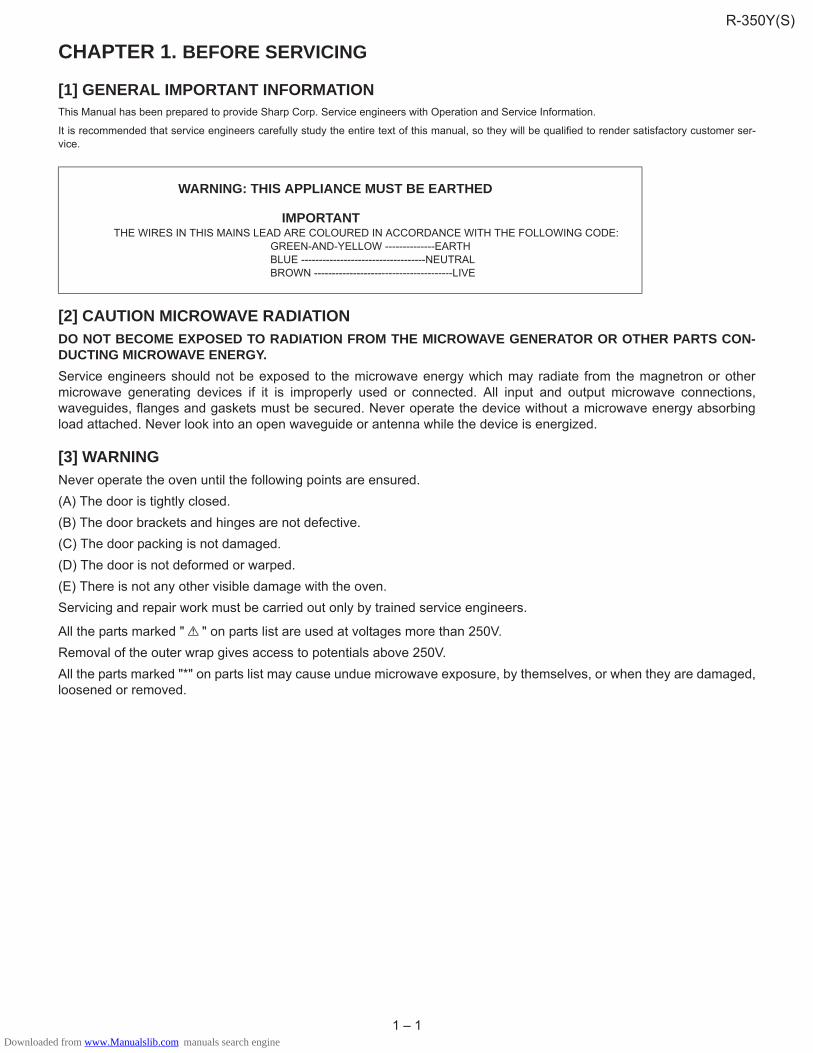
[1] GENERAL IMPORTANT INFORMATIONThis Manual has been prepared to provide Sharp Corp. Service engineers with Operation and Service Information.
It is recommended that service engineers carefully study the entire text of this manual, so they will be qualified to render satisfactory customer ser-vice.
[2] CAUTION MICROWAVE RADIATIONDO NOT BECOME EXPOSED TO RADIATION FROM THE MICROWAVE GENERATOR OR OTHER PARTS CON-DUCTING MICROWAVE ENERGY.Service engineers should not be exposed to the microwave energy which may radiate from the magnetron or othermicrowave generating devices if it is improperly used or connected. All input and output microwave connections,waveguides, flanges and gaskets must be secured. Never operate the device without a microwave energy absorbingload attached. Never look into an open waveguide or antenna while the device is energized.
[3] WARNINGNever operate the oven until the following points are ensured.(A) The door is tightly closed.(B) The door brackets and hinges are not defective.(C) The door packing is not damaged.(D) The door is not deformed or warped.(E) There is not any other visible damage with the oven.Servicing and repair work must be carried out only by trained service engineers.
All the parts marked " " on parts list are used at voltages more than 250V.Removal of the outer wrap gives access to potentials above 250V.All the parts marked "*" on parts list may cause undue microwave exposure, by themselves, or when they are damaged,loosened or removed.
WARNING: THIS APPLIANCE MUST BE EARTHED
IMPORTANT THE WIRES IN THIS MAINS LEAD ARE COLOURED IN ACCORDANCE WITH THE FOLLOWING CODE: GREEN-AND-YELLOW --------------EARTH BLUE -----------------------------------NEUTRAL BROWN ---------------------------------------LIVE
R-350Y(S)
Downloaded from www.Manualslib.com manuals search engine

2 – 1
CHAPTER 2. WARNING TO SERVICE PERSONNELThe ovens contain circuitry capable of producing very high voltage and current, contact with following parts may result in a severe, possibly fatal,electrical shock.
(Example)
Inverter unit, Magnetron, High Voltage Harness etc..
Read the Service Manual carefully and follow all instructions.
[1] Before ServicingCARRY OUT 3D CHECKS.
NOTE: Step 1, 2 and 3 form the basis of the 3D checks.
1. Disconnect the power supply cord, and then remove the outer case.
2. Door opened, and wedged open.
3. Discharge the high voltage capacitors of the inverter unit, by following the procedures below.
3-1. Wait for 60 seconds to discharge the high voltage capacitors of the inverter unit.
3-2. Disconnect the high voltage wire from the magnetron terminal with insulated pliers.
3-3. Make the terminal (metal part) of the high voltage wire contact to the magnetron body with insulated pliers.
3-4. Now, the capacitors of the inverter unit are discharged.
3-5. Reconnect the high voltage wire to the magnetron terminal after discharging.
WARNING: Use the pliers that the portions of their handles are insulated completely to avoid an electric shock.
WARNING: RISK OF ELECTRIC SHOCK. DISCHARGE THE HIGH-VOLTAGE CAPACITOR BEFORE SERVICING.
The high-voltage capacitor remains charged about 60 seconds after the oven has been switched off. Wait for 60 seconds.
Whenever troubleshooting is performed the power supply must be disconnected. It may, in some cases, be necessary to connect the power supplyafter the outer case has been removed, in this event,
1. Disconnect the power supply cord, and then remove the outer case.
2. Open the door and block it open.
3. Wait for 60 seconds to discharge the high voltage capacitors of the inverter unit.
4. Disconnect the high voltage wire from the magnetron terminal with insulated pliers.
5. Make the terminal (metal part) of the high voltage wire contact to the magnetron body with insulated pliers.
6. Now, the capacitors of the inverter unit are discharged.
7. Reconnect the high voltage wire to the magnetron terminal after discharging.
WARNING: Use the pliers that the portions of their handles are insulated completely to avoid an electric shock.
8. Disconnect the leads to the primary of the inverter unit.
9. Ensure that the leads remain isolated from other components and oven chassis by using insulation tape.
10.After that procedure, reconnect the power supply cord.
Don't Touch !Danger High Voltage
R-350Y(S)
Downloaded from www.Manualslib.com manuals search engine

2 – 2
[2] When the testing is completed,1. CARRY OUT 3D CHECKS.
2. CARRY OUT 4R CHECKS.
2-1.Reconnect all leads removed from components during testing.
2-2.Reinstall the outer case.
2-3.Reconnect the power supply cord after the outer case is installed.
2-4.Run the oven and check all function.
[3] After repairing1. CARRY OUT 4R CHECKS.
Ovens should not be run empty. To test for the presence of microwave energy within a cavity, place a cup of cold water on the turntable tray, close thedoor and set the power to 100% and set the microwave timer for two (2) minutes. When the two minutes has elapsed (timer at zero) carefully checkthat the water is now hot. If the water remains cold carry out Before Servicing procedure and re-examine the connections to the component beingtested.
When all service work is completed and the oven is fully assembled, the microwave power output should be checked and microwave leakage testshould be carried out.
[4] Before replacing the Printed Wiring BoardSome normal boards are found in board units that have been returned due to oven failure. So, most of board replacements may arise from poor har-ness connection. Accordingly, before replacing any board that was judged to require its replacement, use the following procedure to re-check that theconnection terminal of a connector has been properly inserted:
1. When the connectors have been incorrectly inserted to the control unit.
2. When latch switch adjustment is incorrectWhen latch switch adjustment is incorrect, symptoms such as no heating, no heating start, no activation even with start button pressed, etc. will occur.
motpmySROTCENNOCBWPCONTROL UNIT RY-2 No heating can be done.
CN-B No heating can be done (even if the door has not been opened). CN-C No heating can be done.(Control signals can not be sent to inverter unit.)CN-A The oven cannot be powered on, no fan motor runs and no oven lamp illuminate.CN-F No heating can be done. (Humidity sensor error)
R-350Y(S)
Downloaded from www.Manualslib.com manuals search engine

3 – 1
CHAPTER 3. PRODUCT SPECIFICATIONSNOITPIRCSEDMETI
Power Requirements230 - 240 Volts 50 HertzSingle phase, 3 wire earthed
Power Consumption Initial : 1.90kW 8.0A Steady : 1.15kW 5.0A
Power Output 1200 watts nominal of RF microwave energy (IEC Test Procedure)Operating frequency 2450 MHz
Case DimensionsWidth 520 mmHeight 310 mmincluding footDepth 442 mm
Turntable Diameter 320 mm
Control Complement
Touch Control SystemClock (1:00 - 12:59)Timer (0 - 99 minutes 99 seconds)Microwave Power for Variable Cooking
POWER LEVEL padNUMBER padsSTOP/CLEAR padINSTANT COOK/START padSENSOR INSTANT ACTION padsSENSOR COOK padsEXPRESS DEFROST padEASY DEFROST padQUICK AND EASY MEALS padMELT SOFTEN padINFO/TIMER pad
Set Weight (Approx.) 17kg
Display100P 100% High90P 90%80P 80%70P 70% Medium High60P 60%50P 50% Medium40P 40%30P 30% Medium Low20P 20%10P 10% Low0P 0%
Power level
R-350Y(S)
Downloaded from www.Manualslib.com manuals search engine

4 – 1
CHAPTER 4. APPEARANCE VIEW
[1] OVEN1. Door open button
2. Oven lamp
3. Door hinges
4. Door safety latches
5. See through door
6. Door seal and sealing surfaces
7. Coupling
8. Wave guide cover
9. Touch control panel
10.Liquid crystal display
11.Ventilation openings
12.Power supply cord
13.Turntable
14.Roller stay
15.Menu label
[2] TOUCH CONTROL PANEL
NOTE: Some one-touch cooking features such as “INSTANT COOK” are disabled after three minutes when the oven is not in use.
These features are automatically enabled when the door is opened and closed or the STOP/CLEAR pad is pressed.
6 2
84 5
3
1
9
10
15
7 13
14
1112
4
Control Panel Display
Indicators
Touch Control Panel Layout
EASYMEALS
INFOTIMER
POWERLEVEL
1200 WATTS
CONVENIENT MENUS
SENSOR COOK
MELTSOFTEN
FRESHVEGETABLES
FROZENVEGETABLES
SENSORREHEAT
JACKETPOTATO
RICEPASTA
EXPRESSDEFROST
EASYDEFROST
MORELESS
QUICKMEALS
NUMBER PADSPress to enter cooking time, clock time, weight of food.
INFO/TIMER PADPress to select demonstration mode, child lock, clock, auto start, info on pads or timer. Press to see the cooking information.
INSTANT COOK/START PADPress to start oven after setting programmes.Press once to cook for 1 minute at HIGH or increase by 1 minute multiples by pressing numerous times during cooking.
POWER LEVEL PADPress to select microwave power setting.If not pressed, HIGH is automatically selected.
STOP/CLEAR PADPress to clear during programming.Press once to stop operation of oven during cooking; press twice to cancel cooking programme.
QUICK MEALS PADPress to select the Quick Meals menu.
CONVENIENT MENUS PADSPress to select Convenient Menus menus.
SENSOR COOK PADSPress to select Sensor Cook menus.
EASY MEALS PADSPress to select the Easy Meals menu
MORE, LESS PADSPress to increase/decrease the time in one minute increments during cooking or to alter the cooking result for the automatic operations.
R-350Y(S)
Downloaded from www.Manualslib.com manuals search engine

5 – 1
CHAPTER 5. OPERATION SEQUENCE
[1] OFF CONDITIONClosing the door activates all door interlock switches (1st. latch switchand 2nd. interlock relay control switch).
MPORTANT
When the oven door is closed, the monitor switch contacts (COM-NC)must be open. When the microwave oven is plugged in a wall outlet,rated voltage is supplied to the noise filter and the control unit.
Figure O-1 on page 14-1
1. The display shows "MICRO-", "WAVE" and "OVEN".
2. To set any programmes or set the clock, you must first touch theSTOP/CLEAR pad.
3. " . 0" appears in the display.
NOTE: When the oven door is opened, the oven lamp comes on atthis time.
[2] MICROWAVE COOKING CONDITION
1. HIGH COOKINGEnter a desired cooking time with the touching NUMBER pad and startthe oven with touching START pad.
Function sequence
Figure O-2 on page 14-1
1. The rated voltage is supplied to the inverter unit.
2. The inverter unit converts the rated voltage into high-voltage andhigh frequency current. And the inverter unit drives the magnetron.
3. The 2450 MHz microwave energy produced in the magnetron gen-erates a wave length of 12.24 cm. This energy is channelledthrough the waveguide (transport channel) into the oven cavity,where the food is placed to be cooked.
4. When the cooking time is up, a signal tone is heard and the relays(RY1+RY2) go back to their home position. The circuits to the ovenlamp, inverter unit and turntable motor are cut off. The fan motorwill operate for one minute after cooking.
5. When the door is opened during a cook cycle, the switches come tothe following condition
The circuits to the inverter unit and turntable motor are cut off when the1st. latch switch and 2nd. interlock relay control switch are made open.The oven lamp remains on even if the oven door is opened after thecooking cycle has been interrupted, because the relay RY1 staysclosed. Shown in the display is the remaining time. The fan motor willoperate for one minute after cooking.
6. MONITOR SWITCH CIRCUIT
The monitor switch is mechanically controlled by oven door, andmonitors the operation of the 1st. latch switch and 2nd. interlockrelay.
1) When the oven door is opened during or after the cycle of acooking program, the 1st. latch switch and 2nd. interlock relaycontrol switch must open their contacts first. After that the con-tacts (COM-NC) of the monitor switch can be closed.
2) When the oven door is closed, the contacts (COM-NC) of themonitor switch must be opened. After that the contacts of the1st. latch switch and 2nd. interlock relay control switch areclosed.
3) When the oven door is opened and the contacts of the 1st. latchswitch and 2nd. interlock relay remain closed. The fuse F10Awill blow, because the monitor switch is closed and a short cir-cuit is caused.
2. VARIABLE OUTPUT POWER COOKINGThere are present eleven (11) microwave power levels. When themicrowave oven is preset for variable cooking power, the output powerof the magnetron is varied according to variable frequency which isgenerated from the inverter unit.
[3] SENSOR COOKING CONDITIONUsing the SENSOR function, the food is cooked without figuring time,power level or quantity. When the oven senses enough steam from thefood, it relays the information to its microprocessor which will calculatethe remaining cooking time and power level needed for best results.When the food is cooked, water vapor is developed. The sensor“senses” the vapor and its resistance increases gradually. When theresistance reaches the value set according to the menu, supplemen-tary cooking is started. The time of supplementary cooking is deter-mined by experiment with each food category and inputted into theLSI.
An example of how sensor works: (JACKET POTATOES)
1. Potatoes at room temperature. Vapor is emitted very slowly.
2. Heat potatoes. Moisture and humidity is emitted rapidly. You cansmell the aroma as it cooks.;
3. Sensor detects moisture and humidity and calculates cooking timeand variable power.
CONNECTED COMPONENTS RELAYOven lamp, Turntable motor RY1
2YRtinu retrevnI3YRrotom naF
CONDITION
SWITCH CONTACT DURING COOKING
DOOR OPEN (NO COOKING)
1st. latch switch COM-NO Closed Open2nd. interlock relay control switch COM-NO Closed Open
Monitor switch COM-NC Open Closed
MICROWAVE
MICROWAVEHUMIDITY SENSOR
R-350Y(S)
Downloaded from www.Manualslib.com manuals search engine
5 – 2
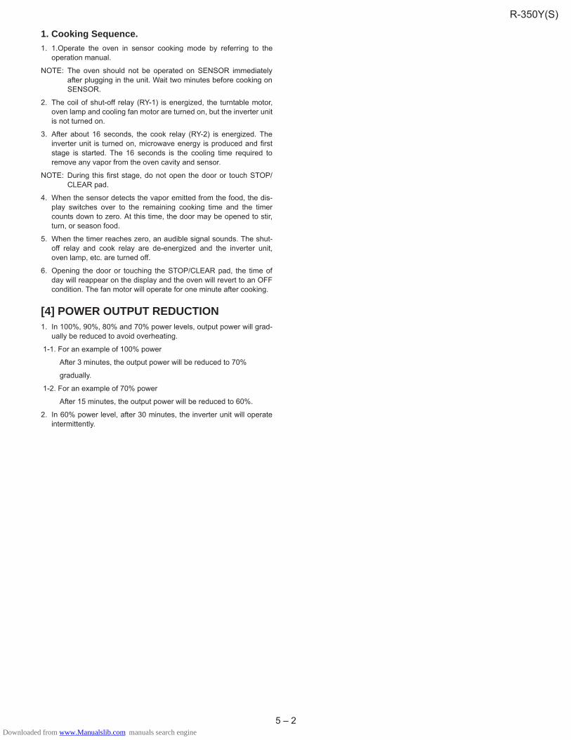
1. Cooking Sequence.1. 1.Operate the oven in sensor cooking mode by referring to the
operation manual.
NOTE: The oven should not be operated on SENSOR immediatelyafter plugging in the unit. Wait two minutes before cooking onSENSOR.
2. The coil of shut-off relay (RY-1) is energized, the turntable motor,oven lamp and cooling fan motor are turned on, but the inverter unitis not turned on.
3. After about 16 seconds, the cook relay (RY-2) is energized. Theinverter unit is turned on, microwave energy is produced and firststage is started. The 16 seconds is the cooling time required toremove any vapor from the oven cavity and sensor.
NOTE: During this first stage, do not open the door or touch STOP/CLEAR pad.
4. When the sensor detects the vapor emitted from the food, the dis-play switches over to the remaining cooking time and the timercounts down to zero. At this time, the door may be opened to stir,turn, or season food.
5. When the timer reaches zero, an audible signal sounds. The shut-off relay and cook relay are de-energized and the inverter unit,oven lamp, etc. are turned off.
6. Opening the door or touching the STOP/CLEAR pad, the time ofday will reappear on the display and the oven will revert to an OFFcondition. The fan motor will operate for one minute after cooking.
[4] POWER OUTPUT REDUCTION1. In 100%, 90%, 80% and 70% power levels, output power will grad-
ually be reduced to avoid overheating.
1-1. For an example of 100% power
After 3 minutes, the output power will be reduced to 70%
gradually.
1-2. For an example of 70% power
After 15 minutes, the output power will be reduced to 60%.
2. In 60% power level, after 30 minutes, the inverter unit will operateintermittently.
R-350Y(S)
Downloaded from www.Manualslib.com manuals search engine

6 – 1
CHAPTER 6. FUNCTION OF IMPORTANT COMPONENTS
[1] DOOR OPEN MECHANISMThe door is opened by pushing the open button on the control panel,refer to the Figure D-1.
When the open button is pushed, the open button pushes up theswitch lever, and then the switch lever pushes up the latch head. Thelatch heads are moved upward and released from latch hook. Now thedoor will open.
Figure D-1. Door Open Mechanism
[2] 1ST. LATCH SWITCH AND 2ND. INTER-LOCK RELAY CONTROL SWITCH1. When the oven door is closed, the contacts (COM-NO) must be
closed.
2. When the oven door is opened, the contacts (COM-NO) must beopened.
[3] MONITOR SWITCH 1. When the oven door is closed, the contacts (COM-NC) must be
opened.
2. When the oven door is opened, the contacts (COM-NC) must beclosed.
3. If the oven door is opened and the contacts (COM-NO) of the 1st.latch switch and 2nd. interlock relay fail to open, the fuse F10Ablows simultaneously with closing the contacts (COM-NC) of themonitor switch.
CAUTION: BEFORE REPLACING A BLOWN FUSE F10A TEST THE1ST. LATCH SWITCH, 2ND.INTERLOCK RELAY, MONI-TOR SWITCH AND MONITOR RESISTOR FOR PROPEROPERATION.
[4] FUSE F10A1. The fuse F10A blows when the contacts (COM-NO) of the 1st. latch
switch and 2nd. interlock relay remain closed with the oven dooropen and when the monitor switch closes.
2. If the wire harness or electrical components are short-circuited, thisfuse F10A blows to prevent an electric shock or fire hazard.
[5] INVERTER UNITThe inverter unit converts the rated voltage into high-voltage and high-frequency current and drives the magnetron.
[6] OVEN TEMPERATURE FUSEThe temperature fuse, located on the top of the oven cavity, isdesigned to prevent damage to the oven by fire. If the food load isovercooked, by either error in cook time or defect in the control unit,the temperature fuse will open.Under normal operation, the tempera-ture fuse remains closed. However, when abnormally high tempera-tures are reached within the oven cavity, the temperature fuse willopen at 150�C, causing the oven to shut down.
[7] TURNTABLE MOTORThe turntable motor drives the turntable roller assembly to rotate theturntable.
[8] FAN MOTORThe fan motor drives a blade which draws external cool air.This coolair is directed through the air vents surrounding the magnetron andcools the magnetron. This air is channelled through the oven cavity toremove steam and vapours given off from the heating foods. It is thenexhausted through the exhausting air vents at the oven cavity.
[9] NOISE FILTERThe noise filter prevents the radio frequency interference that mightflow back in the power circuit.
[10] HUMIDITY SENSORThis sensor detects the humidity from the food which is being cooked,to control its automatic cooking.
Latch Hook
Monitor Switch
2nd. InterlockRelay ControlSwitch
1st Latch Switch
LatchHeads
Door
R-350Y(S)
Downloaded from www.Manualslib.com manuals search engine

7 – 1
CHAPTER 7. TROUBLESHOOTING GUIDEWhen troubleshooting the microwave oven, it is helpful to follow theSequence of Operation in performing the checks. Many of the possiblecauses of trouble will require that a specific test be performed. Thesetests are given a procedure letter which will be found in the “Test Pro-cedure”section.
IMPORTANT:
If the oven becomes inoperative because of a blown fuse F10A in the1st. latch switch - 2nd. interlock relay - monitor switch circuit, check the1st. latch switch, 2nd.interlock relay and monitor switch before replac-ing the fuse F10A.
MA
GN
ETR
ON
INV
ER
TER
UN
IT
1ST.
LATC
HS
WIT
CH
2ND
.IN
TER
LOC
KR
ELA
YC
ON
TRO
LS
WIT
CH
MO
NIT
OR
SW
ITC
HTE
MP
ER
ATU
RE
FUS
E(O
VE
N)
FAN
MO
TOR
TUR
NTA
BLE
MO
TOR
FUS
EF1
0A
TOU
CH
CO
NTR
OL
PA
NE
LK
EY
UN
ITFU
SE
F1O
NP
.W.B
.P
OW
ER
SU
PP
LYC
OR
DS
HO
RTE
DW
IRE
HA
RN
ES
SO
PE
NE
DW
IRE
HA
RN
ES
SO
VE
NLA
MP
WA
LLO
UTL
ET
MIS
AD
JUS
TME
NT
SW
ITC
HH
OM
EFU
SE
OR
BR
EA
KE
RB
LOC
KE
DC
OO
LIN
GFA
NB
LOC
KE
DV
EN
TILA
TIO
N
NO
ISE
FILT
ER
HU
MID
ITY
SE
NS
OR
TEST PROCEDURE
CK = Check / RE = Replace
RE CK CK RE CK CK CK CK CK
CONDITION PROBLEM
POSSIBLE CAUSEAND
DEFECTIVE PARTS
ON
SENSORCOOKINGCONDITION
CONDITION
OFFCONDITION
Home fuse blows when powersupply cord is plugged into walloutlet.FUSE F10A blows when powersupply cord is plugged into walloutlet.
Display does not show anythingwhen power supply cord is plug-ged into wall outlet.Display does not operate proper-ly when STOP/CLEAR pad istouched.Oven lamp does not light at dooropened. (Display appears.)
Oven lamp does not light (Dis-play appears.)Fan motor does not operate.(Display appears.)Turntable motor does not oper-ate. (Display appears.)
Oven does not start when theSTART pad is touched. (Dis-play appears)
Oven or any electrical parts doesnot stop when cooking time is 0or STOP/CLEAR pad is touched.
Oven goes into cook cycle butshuts down before end of cook-ing cycle.
Oven stops at 16 sec. after starting.
Humidity sensor does not end dur-ing Sensor cooking condition.(Oven doesnot shut off after a cupof water is boiling by sensor cook-ing.)
Oven seems to be operating butlittle or no heat is produced inoven load. (Microwave power lev-el is set at 100%)Oven does not seems to be oper-ating properly when 90% 10%is set.(Oven operates properly at 100%and then the STOP/CLEAR padis touched the oven stops.)
A B B B C D D E G H I JFPage 9-1
R-350Y(S)
Downloaded from www.Manualslib.com manuals search engine
8 – 1
CHAPTER 8. TEST PROCEDURES
[1] A: MAGNETRON (MG) TEST
CARRY OUT 3D CHECKS.
Isolate the magnetron from the high voltage circuit by removing all leads connected to the filament terminal.
To test for an open circuit filament use an ohmmeter to make a continuity test between the magnetron filament terminals, the meter should show areading of less than 1 ohm.
To test for a short circuit filament to anode condition, connect ohmmeter between one of the filament terminals and the case of the magnetron(ground). This test should be indicated an infinite resistance. If a low or zero resistance reading is obtained then the magnetron should be replaced.
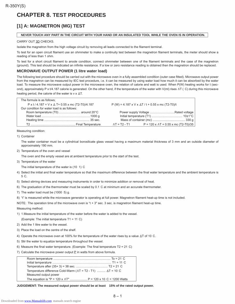
MICROWAVE OUTPUT POWER (1 litre water load)The following test procedure should be carried out with the microwave oven in a fully assembled condition (outer case fitted). Microwave output powerfrom the magnetron can be measured by IEC test procedure, i.e. it can be measured by using water load how much it can be absorbed by the waterload. To measure the microwave output power in the microwave oven, the relation of calorie and watt is used. When P(W) heating works for t (sec-ond), approximately P x t/4.187 calorie is generated. On the other hand, if the temperature of the water with V(ml) rises T (�C) during this microwaveheating period, the calorie of the water is v x T.
Measuring condition:
1) Container
The water container must be a cylindrical borosilicate glass vessel having a maximum material thickness of 3 mm and an outside diameter ofapproximately 190 mm.
2) Temperature of the oven and vessel
The oven and the empty vessel are at ambient temperature prior to the start of the test.
3) Temperature of the water
The initial temperature of the water is (10�1)�C
4) Select the initial and final water temperature so that the maximum difference between the final water temperature and the ambient temperature is5�C.
5) Select stirring devices and measuring instruments in order to minimize addition or removal of heat.
6) The graduation of the thermometer must be scaled by 0.1�C at minimum and an accurate thermometer.
7) The water load must be (1000�5) g.
8) “t” is measured while the microwave generator is operating at full power. Magnetron filament heat-up time is not included.
NOTE: The operation time of the microwave oven is “t + 3" sec. 3 sec. is magnetron filament heat-up time.
Measuring method:
1) 1.Measure the initial temperature of the water before the water is added to the vessel.
(Example: The initial temperature T1 = 11�C)
2) Add the 1 litre water to the vessel.
3) Place the load on the centre of the shelf.
4) Operate the microwave oven at 100% for the temperature of the water rises by a value T of 10�C.
5) Stir the water to equalize temperature throughout the vessel.
6) Measure the final water temperature. (Example: The final temperature T2 = 21�C)
7) Calculate the microwave power output P in watts from above formula.
JUDGEMENT: The measured output power should be at least � 15% of the rated output power.
NEVER TOUCH ANY PART IN THE CIRCUIT WITH YOUR HAND OR AN INSULATED TOOL WHILE THE OVEN IS IN OPERATION.
The formula is as follows; P x t / 4.187 = V x T+ 0.55 x mc (T2-T0)/4.187 P (W) = 4.187 x V x T / t + 0.55 x mc (T2-T0)/t Our condition for water load is as follows: Room temperature (T0) ......................... around 20°C Power supply Voltage .............................Rated voltage Water load .........................................................1000 g Initial temperature (T1) .................................... 10±1°C Heating time ..................................................... 35 sec. Mass of container (mc) ...................................... 330 g T2 .................................................... Final Temperature T = T2 - T1 P = 120 x T + 0.55 x mc (T2-T0)/35
Room temperature ................................................................... To = 21�C Initial temperature ..................................................................... T1 = 11�C Temperature after (35+ 3) = 38 sec. ..................................... T2 = 21�C Temperature difference Cold-Warm ( T = T2 - T1) .......... T = 10�C Measured output power The equation is "P = 120 x T" .................... P = 120 x 10�C = 1200 Watts
R-350Y(S)
Downloaded from www.Manualslib.com manuals search engine

8 – 2
CAUTION: 1�C CORRESPONDS TO 120 WATTS. REPEAT MEASUREMENT IF THE POWER IS INSUFFICIENT.
[2] B: SWITCH TESTCARRY OUT 3D CHECKS.
Isolate the switch to be tested and using an ohmmeter check between the terminals as described in the following table.
If incorrect readings are obtained, make the necessary switch adjustment or replace the switch.
CARRY OUT 4R CHECKS.
[3] C: TEMPERATURE FUSE TESTCARRY OUT 3D CHECKS.
Disconnect the leads from the terminals of the temperature fuse. Then using an ohmmeter, make a continuity test across the two terminals asdescribed in the below.
If incorrect readings are obtained, replace the temperature fuse.
An open circuit temperature fuse (OVEN) indicates that the foods in the oven may catch fire, this may be due to over heating produced by impropersetting of the cooking time or failure of the control panel.
CARRY OUT 4R CHECKS.
[4] D: MOTOR WINDING TESTCARRY OUT 3D CHECKS.
Disconnect the leads from the motor. Using an ohmmeter, check the resistance between the two terminals as described in the table below.
If incorrect readings are obtained, replace the motor.
CARRY OUT 4R CHECKS.
[5] E: FUSE F10ACARRY OUT 3D CHECKS.
1. If the fuse F10A is blown, there could be shorts or ground in electrical parts or wire harness.Check them and replace the defective parts or repairthe wire harness.
2. If the fuse F10A is blown when the door is opened, check the 1st. latch switch, 2nd. interlock relay and monitor switch.
If the fuse F10A is blown by incorrect door switching replace the defective switch(s) and the fuse F10A.
CARRY OUT 4R CHECKS.
CAUTION: ONLY REPLACE FUSE F10A WITH THE CORRECT VALUE REPLACEMENT.
Table: Terminal Connection of SwitchPlunger Operation COM to NO COM to NC COM; Common terminalReleased Open circuit Short circuit NO; Normally open terminal Depressed Short circuit Open circuit NC; Normally close terminal
Table: Temperature Fuse Test
Parts Name Temperature of “ON” condition (closed circuit).
Temperature of “OFF” condition (open circuit).
Indication of ohmmeter (When room temperature is approx. 20�C.)
Temperature fuse 150�C This is not resetable type. Above 150� tiucric desolCC
Table: Resistance of Motor
Motorsrotom elbatnruTrotom naF
RMOTEA450WRZZ RMOTEA475WRZZ RMOTDA253WRZZ RMOTDA289WRZZ RMOTDA302WRE0Resistance Approximately 384� Approximately 333� Approximately 14.5k� Approximately 13.5k� Approximately 14.7k�
1000g
1000g1000g
T1 C T2 CHeat up for 38 sec.
R-350Y(S)
Downloaded from www.Manualslib.com manuals search engine

8 – 3
[6] F: NOISE FILTER TEST
CARRY OUT 3D CHECKS.
Disconnect the leads from the terminals of the noise filter. Using an ohmmeter,check between the terminals as described in the following table.
If incorrect readings are obtained, replace the noise filter unit.
CARRY OUT 4R CHECKS.
[7] G: TOUCH CONTROL PANEL ASSEMBLY TESTThe touch control panel consists of circuits including semiconductors such as LSI, ICs, etc. Therefore, unlike conventional microwave ovens, propermaintenance cannot be performed with only a voltmeter and ohmmeter. In this service manual, the touch control panel assembly is divided into twounits, Control Unit and Key Unit, and also the Control Unit is divided into two units, CPU Unit and Power Unit, and troubleshooting by unit replacementis described according to the symptoms indicated.
1. Key Unit. Note: Check key unit ribbon connection before replacement.
The following symptoms indicate a defective key unit. Replace the control unit assembly.
1) When touching the pads, a certain pad produces no signal at all.
2) When touching a number pad, two figures or more are displayed.
3) When touching the pads, sometimes a pad produces no signal.
2. Control Unit.
The following symptoms indicate a defective control unit. Before replacing the control unit, perform the Key unit test ([8] H) to determine if controlunit is faulty.
1) In connection with pads.
a) When touching the pads, a certain group of pads do not produce a signal.
b) When touching the pads, no pads produce a signal.
2) In connection with indicators.
a) At a certain digit, all or some segments do not light up.
b) At a certain digit, brightness is low.
c) Only one indicator does not light up.
d) The corresponding segments of all digits do not light up; or they continue to light up.
e) Wrong figure appears.
f) A certain group of indicators do not light up.
g) The figure of all digits flicker.
3) Other possible troubles caused by defective control unit.
a) Buzzer does not sound or continues to sound.
b) Clock does not operate properly.
c) Cooking is not possible.
MEASURING POINT INDICATION OF OHMMETERBetween N and L Approximately 150 k�Between terminal N and WHITE Short circuitBetween terminal L and RED Short circuit
REDWHT
FUSEF10A
N L
NOISE SUPPRESSION COIL
LINE BYPASS CAPACITOR0.0047μF /AC250V
LINE BYPASS CAPACITOR0.0047μF /AC250V
LINE CROSS CAPACITOR2.2μF /AC250V
NOISEFILTERUNIT
R-350Y(S)
Downloaded from www.Manualslib.com manuals search engine

8 – 4
[8] H: KEY UNIT (MEMBRANE SWITCH) TEST1. CARRY OUT 3D CHECKS.
2. If the display fails to clear when the STOP/CLEAR pad is depressed, first verify the flat ribbon cable is making good contact, verify that the 2nd.Interlock relay control switch operates properly; that is the contacts are closed when the door is closed and open when the door is open.
3. If the 2nd. Interlock relay control switch is good, disconnect the flat ribbon cable that connects the key unit to the control unit and make sure the2nd. interlock relay control switch is closed (either close the door or short the 2nd. interlock relay control switch connector).
4. Disconnect the leads to the primary of the inverter unit.
5. Ensure that the leads remain isolated from other components and oven chassis by using insulation tape.
6. After that procedure, reconnect the power supply cord.
7. Use the key unit matrix indicated on the control panel schematic and place a jumper wire between the pins that correspond to the STOP/CLEARpad making momentary contact. If the control unit responds by clearing with a beep the key unit is faulty and must be replaced. If the control unitdoes not respond, it is faulty and must be replaced. If a specific pad does not respond, the above method may be used (after clearing the controlunit) to determine if the control unit or keypad is at fault.
8. CARRY OUT 4R CHECKS.
[9] I: PROCEDURES TO BE TAKEN WHEN THE FUSE F1 ON THE PRINTED WIRING BOARD(PWB) IS OPENTo protect the electronic circuits, this model is provided with the FUSE F1 added to the primary on the PWB. If the FUSE F1 is open, follow the trou-bleshooting guide given below for repair.
CARRY OUT 3D CHECKS.
NOTE: *At the time of making these repairs, make a visual inspection of the varistor. Check for burned damage and examine the transformer with atester for the presence of layer short-circuit (check the primary coil resistance). If any abnormal condition is detected, replace the control unit.
CARRY OUT 4R CHECKS.
[10] J: HUMIDITY SENSOR TESTChecking the initial sensor cooking conditionWARNING: The oven should be fully assembled before following procedure.
1) The oven should be plugged in at least two minutes before sensor cooking.
2) Room temperature should not exceed 95�F (35�C).
3) The unit should not be installed in any area where heat and steam are generated. The unit should not be installed, for example, next to a conven-tional surface unit. Refer to the “INSTALLATION INSTRUCTIONS” of the operation manual.
4) Exhaust vents are provided on the back of the unit for proper cooling and air flow in the cavity. To permit adequate ventilation, be sure to install soas not to block these vents. There should be some space for air circulation.
5) Be sure the exterior of the cooking container and the interior of the oven are dry. Wipe off any moisture with a dry cloth or paper towel.
NOITCERROC RO ESUACECNERRUCCOSPETS1 The rated AC voltage is not present primary side of low voltage transformer. Check supply voltage and oven power cord.
2 The rated AC voltage is present to primary side of low voltage transformer. Low voltage transformer or secondary circuit defective.Replace the control unit.
.tinu lortnoc eht ecalpeR*.nwolb si 1F esuf ehT3
< KEY UNIT >
313236 35 34 333738G1G2G3G4G5G6G7G8
G9
G10
G11
G12
(G13)
EASYDEFORST
SENSORREHEAT
INFOTIMER
3
2
1 654
7 8 9
0POWERLEVEL
LESS
RICEPASTA
STOPCLEAR
FRESHVEGETABLES
MORE
QUICK MEALS
JACKETPOTATO
FROZENVEGETABLES
EASYMEALS
EXPRESSDUNNER PLATE
MELTSOFTEN
INSTANT COOKSTART
39
40
41
42
43
R-350Y(S)
Downloaded from www.Manualslib.com manuals search engine
8 – 5
6) The Sensor works with food at normal storage temperature. For example, chicken pieces would be at refrigerator temperature and canned soup atroom temperature.
7) Avoid using aerosol sprays or cleaning solvents near the oven while using Sensor settings. The sensor will detect the vapor given of by the sprayand turn off before food is properly cooked.
8) If the sensor has not detected the vapor of the food, ERROR will appear and the oven will shut off.
Water load cooking testWARNING: The oven should be fully assembled before following procedure.
Make sure the oven has been plugged in at least two minutes before checking sensor cook operation. The cabinet should be installed and screwstightened.
1) Fill approximately 200 milliliters (7.2 oz) of tap water in a 1000 milliliter measuring cup.
2) Place the container on the center of tray in the oven cavity.
3) Close the door.
4) Touch the POWER LEVEL pad, the number pad 1, the POWER LEVEL pad, the number pad 2 and the POWER LEVEL pad, then open the doorand touch the START pad within 10 seconds. Then, close the door. And touch the number pads 1 once and the number pad 4 once. Now, the ovenis in the sensor cooking condition, and “AH20”, “SENSOR” and “COOK” will appear in the display.
5) The oven turns off automatically, and the time for detecting moisture will be displayed.
If ERROR is displayed or the oven does not turn off, replace the humidity sensor or check the control unit, refer to explanation below.
1. TESTING METHOD FOR HUMIDITY SENSOR AND/OR CONTROL UNITTo determine if the sensor is defective, the simplest method is to replace it with a new replacement sensor.
1) Disconnect the power supply cord, and then remove outer case.
2) Open the door and block it open.
3) Discharge high voltage capacitor.
4) Remove the humidity sensor.
5) Install the new humidity sensor.
6) Reconnect all leads removed from components during testing.
7) Re-install the outer case (cabinet).
8) Reconnect the power supply cord after the outer case is installed.
9) Reconnect the oven to the power supply and check the sensor cook operation as follows:
a) Fill approximately 200 milliliters (7.2 oz) of tap water in a 1000 milliliter measuring cup.
b) Place the container on the center of tray in the oven cavity.
c) Close the door.
d) Touch the POWER LEVEL pad, the number pad 1, the POWER LEVEL pad, the number pad 2 and the POWER LEVEL pad, then open thedoor and touch the START pad within 10 seconds. Then, close the door. And touch the number pads 1 once and the number pad 4 once.
e) The control panel is in automatic Sensor operation.
f) The oven turns off automatically, and the time for detecting moisture will be displayed.
If new sensor dose not operate properly, the problem is with the control unit, and refer to explanation below.
2. CHECKING CONTROL UNIT1) Disconnect the power supply cord, and then remove outer case.
2) Open the door and block it open.
3) Discharge high voltage capacitor.
4) Disconnect the sensor connector that is mounted to control panel.
5) Then connect the dummy resistor circuit (see fig.) to the sensor connector of control panel.
6) Disconnect the leads to the primary of the inverter unit.
7) Ensure that these leads remain isolated from other components and oven chassis by using insulation tape.
8) After that procedure, re-connect the power supply cord.
9) Check the sensor cook operation proceed as follows:
a) Close the door. Touch the POWER LEVEL pad, the number pad 1, the POWER LEVEL pad, the number pad 2 and the POWER LEVEL pad,then open the door and touch the START pad within 10 seconds. Then, close the door. And touch the number pads 1 once and the number pad4 once.
b) The control panel is in the sensor cooking operation.
c) After approximately 25 seconds, push plunger of select switch for more than 3 seconds. This condition is same as judgement by humidity sen-sor.
d) After approximately 3 seconds, the display shows “X X. X X “ which is the time for detecting moisture.
R-350Y(S)
Downloaded from www.Manualslib.com manuals search engine

8 – 6
If the above is not the case, the control unit is probably defective.
If the above is proper, the humidity sensor is probably defective.
10) Disconnect the power supply cord, and then remove outer case.
11) Open the door and block it open.
12) Discharge high voltage capacitor.
13) Disconnect the dummy resistor circuit from the sensor connector of control panel.
14) Carry out necessary repair.
15) Reconnect all leads removed from components during testing and repairing.
16) Re-install the outer case (cabinet).
17) Reconnect the power supply cord after the outer case is installed. Run the oven and check all functions.
18) Carry out “Water load cooking test” again and ensure that the oven works properly.
Sensor Dummy Resistor Circuit
Plunger
NCNO
COM
COM NO
NCR3 R4
R1
R2
123
F-1F-2F-3
To connector (F)on Control Unit.
CONNECTOR
R-350Y(S)
Downloaded from www.Manualslib.com manuals search engine

9 – 1
CHAPTER 9. CHECK IN THE EVENT OF NO MICROWAVE COOKINGCheck of high voltage sections is very dangerous. Therefore, after the inverter boards (M and AC3) and 230 - 240V at the primary terminal are con-firmed to be satisfactory, disconnect the main power and wait for at least one (1) minute before starting the check.
Check of individual components is done with the high voltage circuit wiring disconnected.
*1 Disconnect only the inverter unit terminals M and AC3. Then measure voltage between CN-A pins #1 and #3 (between PD 100 2P and 1P) with
an analog tester while performing heating operation.
*2 If a value measured by a digital tester is unstable, connect a resistor of 10 k� to 100 k� between the pins #1 and #3 to measure the value.
YES
YES
YES
YES
NO NO
NO
NO
NO
NO
YES
YES
YES
YES
NO
NO
YES
NO
Check
(Inverter boards M, AC3, CN-A and F&FA, and magnetron F and FA)
(Function is normal.)
(Function is normal.)
(Function is not normal.)
(Function is not normal.)
Is there a voltage of 230 - 240V between theprimary terminal ends of the inverter unit?
Replace the control board.
Is there a voltage of about 0.4 - 0.5V DC between theinverter CN-A pins #1(negative) and #3 (positive)?*1, *2
Adjust the latch base angle.Check the secondary interlock switch.
In this case, check the high-voltagediodes (D120 and D121) of theinverter unit for a short circuit.
Replace the magnetron.
Check is finished.
Is the secondary interlock switch ON?
Is the fan motor running? Is there a voltage of about 230 - 240V betweenthe fan motor terminal ends? Replace the fan motor.
Is wiring on the high voltage side correct?Have the terminals been completely inserted?
Correct the wiring.Completely insert the harnesses.
Is there continuity between the magnetron terminals?
Is there a short circuit between the magnetron heaterterminal and any metal part of the magnetron body?
Are the magnetron cooling fins easily deformed?Has the magnet cracked?
Replace the inverter board.
R-350Y(S)
Downloaded from www.Manualslib.com manuals search engine

9 – 2
Adjustment of microwave powerThe microwave power (100% power level) can be adjusted as follows.
At step 10, adjust the power so that the "3A" should be indicated at "YY" in the display for this model.
Step Operation Display Indicator Sound Note. 0
1 POWER LEVEL
2 1 (manual setting)
3 POWER LEVEL
4 2
5 POWER LEVEL
6 (door open)
7 START (set aging mode) Set aging mode.
8 (door close)
9 8 0 XX COOK Start power adjust(power)
10 1 or 0 0 YY 1 : power up0 : power down
11 START 1 YY Fix power
Within10 sec.
R-350Y(S)
Downloaded from www.Manualslib.com manuals search engine
10 – 1
CHAPTER 10. SERVICING FOR TOUCH CONTROL PANEL
[1] SERVICING FOR TOUCH CONTROL PANEL
1. Precautions for Handling Electronic ComponentsThis unit uses CMOS LSI in the integral part of the circuits.When han-dling these parts, the following precautions should be strictly followed.CMOS LSI have extremely high impedance at its input and output ter-minals. For this reason, it is easily influenced by the surrounding highvoltage power source, static electricity charge in clothes, etc. andsometimes it is not fully protected by the built-in protection circuit.
In order to protect CMOS LSI.
1) When storing and transporting, thoroughly wrap them in aluminiumfoil. Also wrap all PW boards containing them in aluminium foil.
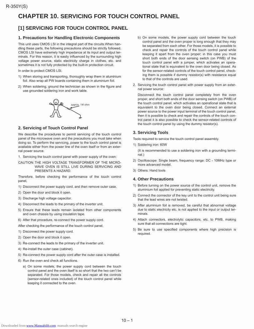
2) When soldering, ground the technician as shown in the figure anduse grounded soldering iron and work table.
2. Servicing of Touch Control PanelWe describe the procedures to permit servicing of the touch controlpanel of the microwave oven and the precautions you must take whendoing so. To perform the servicing, power to the touch control panel isavailable either from the power line of the oven itself or from an exter-nal power source.
1. Servicing the touch control panel with power supply of the oven:
CAUTION: THE HIGH VOLTAGE TRANSFORMER OF THE MICRO-WAVE OVEN IS STILL LIVE DURING SERVICING ANDPRESENTS A HAZARD.
Therefore, before checking the performance of the touch controlpanel,
1) Disconnect the power supply cord, and then remove outer case.
2) Open the door and block it open.
3) Discharge high voltage capacitor.
4) Disconnect the leads to the primary of the inverter unit.
5) Ensure that these leads remain isolated from other componentsand oven chassis by using insulation tape.
6) After that procedure, re-connect the power supply cord.
After checking the performance of the touch control panel,
1) Disconnect the power supply cord.
2) Open the door and block it open.
3) Re-connect the leads to the primary of the inverter unit.
4) Re-install the outer case (cabinet).
5) Re-connect the power supply cord after the outer case is installed.
6) Run the oven and check all functions.
a) On some models, the power supply cord between the touchcontrol panel and the oven itself is so short that the two can’t beseparated. For those models, check and repair all the controls(sensor-related ones included) of the touch control panel whilekeeping it connected to the oven.
b) On some models, the power supply cord between the touchcontrol panel and the oven proper is long enough that they maybe separated from each other. For those models, it is possible tocheck and repair the controls of the touch control panel whilekeeping it apart from the oven proper; in this case you mustshort both ends of the door sensing switch (on PWB) of thetouch control panel with a jumper, which activates an opera-tional state that is equivalent to the oven door being closed. Asfor the sensor-related controls of the touch control panel, check-ing them is possible if dummy resistor(s) with resistance equalto that of the controls are used.
2. Servicing the touch control panel with power supply from an exter-nal power source:
Disconnect the touch control panel completely from the ovenproper, and short both ends of the door sensing switch (on PWB) ofthe touch control panel, which activates an operational state that isequivalent to the oven door being closed. Connect an externalpower source to the power input terminal of the touch control panel,then it is possible to check and repair the controls of the touch con-trol panel it is also possible to check the sensor-related controls ofthe touch control panel by using the dummy resistor(s).
3. Servicing ToolsTools required to service the touch control panel assembly.
1) Soldering iron: 60W
(It is recommended to use a soldering iron with a grounding termi-nal.)
2) Oscilloscope: Single beam, frequency range: DC - 10MHz type ormore advanced model.
3) Others: Hand tools
4. Other Precautions1) Before turning on the power source of the control unit, remove the
aluminium foil applied for preventing static electricity.
2) Connect the connector of the key unit to the control unit being surethat the lead wires are not twisted.
3) After aluminium foil is removed, be careful that abnormal voltagedue to static electricity etc. is not applied to the input or output ter-minals.
4) Attach connectors, electrolytic capacitors, etc. to PWB, makingsure that all connections are tight.
5) Be sure to use specified components where high precision isrequired.
approx. 1M ohm
R-350Y(S)
Downloaded from www.Manualslib.com manuals search engine

11 – 1
CHAPTER 11. PRECAUTIONS FOR USING LEAD-FREE SOLDER1. Employing lead-free solderThe "Main PWB" of this model employs lead-free solder. This is indicated by the "LF" symbol printed on the PWB and in the service manual. The suf-fix letter indicates the alloy type of the solder.
Example:
2. Using lead-free wire solderWhen repairing a PWB with the "LF" symbol, only lead-free solder should be used. (Using normal tin/lead alloy solder may result in cold solderedjoints and damage to printed patterns.)
As the melting point of lead-free solder is approximately 40�C higher than tin/lead alloy solder, it is recommend that a dedicated bit is used, and thatthe iron temperature is adjusted accordingly.
3. SolderingAs the melting point of lead-free solder (Sn-Ag-Cu, Sn-Cu-Ni) is higher and has poorer wettability, (flow), to prevent damage to the land of the PWB,extreme care should be taken not to leave the bit in contact with the PWB for an extended period of time. Remove the bit as soon as a good flow isachieved. The high content of tin in lead free solder will cause premature corrosion of the bit. To reduce wear on the bit, reduce the temperature orturn off the iron when it is not required.
Leaving different types of solder on the bit will cause contamination of the different alloys, which will alter their characteristics, making good solderingmore difficult. It will be necessary to clean and replace bits more often when using lead-free solder. To reduce bit wear, care should be taken to cleanthe bit thoroughly after each use.
Indicates lead-free solder of tin, silver and copper Indicates lead-free solder of tin, copper and nickel
R-350Y(S)
Downloaded from www.Manualslib.com manuals search engine

12 – 1
CHAPTER 12. COMPONENT REPLACEMENT AND ADJUSTMENT PROCE-DURE
[1] BEFORE OPERATING
Microwave ovens contain circuitry capable of producing very high voltage and current, contact with following parts may result in severe, possibly fatal,electric shock.
(Example)
High Voltage Capacitor, Inverter Unit, Magnetron, High Voltage Rectifier Assembly, High Voltage Fuse, High Voltage Harness etc.
WARNING: Avoid possible exposure to microwave energy. Please follow the instructions below before operatingthe oven.
1) Disconnect the power supply cord.
2) Make sure that a definite “click” can be heard when the microwaveoven door is unlatched. (Hold the door in a closed position with onehand, then push the door open button with the other, this causesthe latch leads to rise, it is then possible to hear a “click” as thedoor switches operate.)
3) Visually check the door and cavity face plate for damage (dents,cracks, signs of arcing etc.).
Carry out any remedial work that is necessary before operating theoven.
Do not operate the oven if any of the following conditions exist;
1) Door does not close firmly.
2) Door hinge, support or latch hook is damaged.
3) The door gasket or seal is damaged.
4) The door is bent or warped.
5) There are defective parts in the door interlock system.
6) There are defective parts in the microwave generating and trans-mission assembly.
7) There is visible damage to the oven.
Do not operate the oven:
1) Without the RF gasket (Magnetron).
2) If the wave guide or oven cavity are not intact.
3) If the door is not closed.
4) If the outer case (cabinet) is not fitted.
Please refer to ”OVEN PARTS, CABINET PARTS, DOOR PARTS”, when carrying out any of the following removal procedures:
To prevent an electric shock, take the following precautions.
1. Before wiring,
1) Disconnect the power supply cord.
2) Open the door and block it open.
3) Discharge the high voltage capacitor and wait for 60 seconds.
2. Don't let the wire leads touch to the following parts;
1) High voltage parts:
Magnetron, Inverter unit, High voltage capacitor, High voltagerectifier assembly and High voltage fuse.
2) Hot parts:
Convection heater, Oven lamp, Magnetron, High voltage trans-former and Oven cavity.
3) Sharp edge:
Bottom plate, Oven cavity, Weveguide flange, Chassis supportand other metallic plate.
4) Movable parts (to prevent a fault)
Fan blade, Fan motor, Switch, Switch lever, Open button.
3. Do not catch the wire leads in the outer case cabinet.
4. Insert the positive lock connector certainly until its pin is locked.And make sure that the wire leads should not come off even if thewire leads is pulled.
5. To prevent an error function, connect the wire leads correctly, refer-ring to the Pictorial Diagram.
[2] OUTER CASE CABINET REMOVALTo remove the outer case cabinet, procedure as follows.
1. Disconnect the oven from power supply.
2. Door opened, and wedged open.
3. Remove five (5) screws from rear and one (1) screw along the rightside edge of case.
4. Slide the entire case back out about 1 inch (3 cm) to free it fromretaining clips on the cavity face plate.
5. Lift entire case from the unit.
6. Discharge the high voltage capacitors of the inverter unit, by follow-ing the procedures below.
i) Wait for 60 seconds to discharge the high voltage capacitors ofthe inverter unit.
ii) Disconnect the high voltage wire from the magnetron terminalwith insulated pliers.
iii) Make the terminal (metal part) of the high voltage wire contactto the magnetron body with insulated pliers.
iv) Now, the capacitors of the inverter unit are discharged.
7. Reconnect the high voltage wire to the magnetron terminal afterdischarging.
WARNING: Use the pliers that the portions of their handles are insu-lated completely to avoid an electric shock.
WARNING AGAINST HIGH VOLTAGE:
WARNING FOR WIRING
REMEMBER TO CHECK 3D 1) Disconnect the supply. 3)Discharge high voltage capacitor. 2)Door opened, and wedged open.
R-350Y(S)
Downloaded from www.Manualslib.com manuals search engine

12 – 2
WARNING: RISK OF ELECTRIC SHOCK. DISCHARGE THE HIGH-VOLTAGE CAPACITORS BEFORE SERVICING.
8. Do not operate the oven with the outer case removed.
NOTE: Step 1, 2 and 6 form the basis of the 3D checks.
CAUTION: DISCHARGE HIGH VOLTAGE CAPACITOR BEFORETOUCHING ANY OVEN COMPONENTS OR WIRING.
[3] INVERTER UNIT REPLACEMENT
1. REMOVAL1. CARRY OUT 3D CHECKS.
2. Disconnect the main wire harness from the inverter harness.
3. Disconnect the main wire harness from the connector CN-A in theinverter unit.
4. Disconnect the high voltage wires from the magnetron.
5. Remove the four (4) screws holding the inverter angle to the bottomplate.
6. Remove the inverter angle with the inverter unit from the bottomplate.
7. Disconnect the inverter harness from the inverter unit.
8. Disconnect the high voltage wires from the inverter unit.
9. Remove the one (1) screw which earths the inverter unit to theinverter angle.
10.Remove the two (2) screws holding the inverter unit to the inverterangle.
11.Remove the inverter unit from the inverter angle.
12.Now, the inverter unit is free.
2. RE-INSTALL1. Insert the tab of the inverter unit to the slit of the inverter angle, as
shown in the picture “Tab of inverter unit”.
2. Hold the inverter unit to the inverter angle with the two (2) screws,as shown in the picture “Screws for inverter unit”.
3. Earth the inverter unit to the inverter angle with one (1) screw, asshown in the picture “Tab of inverter unit”.
4. Connect the inverter harness to the inverter unit, referring to thepictorial diagram.
5. Connect the high voltage wires to the inverter unit, referring to thepictorial diagram.
6. Rest the inverter angle with the inverter unit on the bottom platewith the inverter harness terminal side toward the oven face plate.
7. Secure the inverter angle with four (4) screws to the bottom plate.
8. Connect the high voltage wires to the magnetron, referring to thepictorial diagram.
9. Connect the connector of the main wire harness to the connectorCN-A on the inverter unit.
10.Connect the inverter harness to the main wire harness.
11.CARRY OUR 4R CHECKS.
[4] MAGNETRON REMOVAL
1. REMOVAL1. CARRY OUT 3D CHECKS.
2. Disconnect all wire leads from magnetron.
3. Remove the one (1) screw holding the chassis support to the mag-netron.
4. Release the chassis support from the hole of the oven cavity frontflange.
5. Remove the two (2) screws holding air duct to magnetron and ovencavity top plate.
6. Remove the air duct from oven.
7. Carefully remove the four (4) screws holding magnetron towaveguide flange.
8. Remove magnetron with care so that magnetron antenna is not hitby any metal object around antenna.
9. Now, the magnetron is free.
2. REINSTALLATION1. Reinstall the magnetron to waveguide flange with the four (4)
screws.
2. Reinstall the air duct to the oven cavity top plate and the magnetronwith two (2) screws.
3. Insert the end of the chassis support into the hole of the oven cavityfront flange.
4. Hold the other end of the chassis support to the magnetron with theone (1) screw.
5. Reconnect the wire leads to the magnetron. Refer to ”PICTORIALDIAGRAM”.
6. Reinstall outer case and check that the oven is operating properly.
CAUTION: WHEN REPLACING MAGNETRON, BESURE THE R.F.GASKET IS IN PLACE AND MOUNTING SCREWS ARETIGHTENEDSECURELY.
Inverter angle Screw for earthing
Inverter unit
Tab of inverter unit
Picture of Tab of the inverter unit
Screw for earthing
Screws forholding theinverter unit
Picture of Screws of the inverter unit
R-350Y(S)
Downloaded from www.Manualslib.com manuals search engine
12 – 3
[5] POSITIVE LOCK CONNECTOR (NO-CASE TYPE) REMOVAL1. CARRY OUT 3D CHECKS.
2. Push the lever of positive lock� connector.
3. Pull down on the positive lock� connector.
CAUTION: WHEN CONNECTING THE POSITIVE LOCK� CONNEC-TORS TO THE TERMINALS, CONNECT THE POSITIVELOCK� SO THAT THE LEVER FACES YOU.
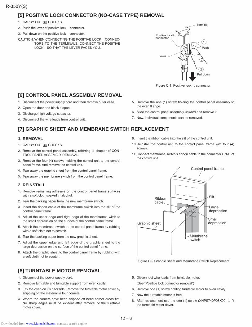
Figure C-1. Positive lock� , connector
[6] CONTROL PANEL ASSEMBLY REMOVAL1. Disconnect the power supply cord and then remove outer case.
2. Open the door and block it open.
3. Discharge high voltage capacitor.
4. Disconnect the wire leads from control unit.
5. Remove the one (1) screw holding the control panel assembly tothe oven fl ange.
6. Slide the control panel assembly upward and remove it.
7. Now, individual components can be removed.
[7] GRAPHIC SHEET AND MEMBRANE SWITCH REPLACEMENT
1. REMOVAL1. CARRY OUT 3D CHECKS.
2. Remove the control panel assembly, referring to chapter of CON-TROL PANEL ASSEMBLY REMOVAL.
3. Remove the four (4) screws holding the control unit to the controlpanel frame. And remove the control unit.
4. Tear away the graphic sheet from the control panel frame.
5. Tear away the membrane switch from the control panel frame.
2. REINSTALL1. Remove remaining adhesive on the control panel frame surfaces
with a soft cloth soaked in alcohol.
2. Tear the backing paper from the new membrane switch.
3. Insert the ribbon cable of the membrane switch into the slit of thecontrol panel frame.
4. Adjust the upper edge and right edge of the membranes witch tothe small depression on the surface of the control panel frame.
5. Attach the membrane switch to the control panel frame by rubbingwith a soft cloth not to scratch.
6. Tear the backing paper from the new graphic sheet.
7. Adjust the upper edge and left edge of the graphic sheet to thelarge depression on the surface of the control panel frame.
8. Attach the graphic sheet to the control panel frame by rubbing witha soft cloth not to scratch.
9. Insert the ribbon cable into the slit of the control unit.
10.Reinstall the control unit to the control panel frame with four (4)screws.
11.Connect membrane switch’s ribbon cable to the connector CN-G ofthe control unit.
Figure C-2.Graphic Sheet and Membrane Switch Replacement
[8] TURNTABLE MOTOR REMOVAL1. Disconnect the power supply cord.
2. Remove turntable and turntable support from oven cavity.
3. Lay the oven on it's backside. Remove the turntable motor cover bysnipping off the material in four corners.
4. Where the corners have been snipped off bend corner areas flat.No sharp edges must be evident after removal of the turntablemotor cover.
5. Disconnect wire leads from turntable motor.
(See “Positive lock connector removal”)
6. Remove one (1) screw holding turntable motor to oven cavity.
7. Now the turntable motor is free.
8. After replacement use the one (1) screw (XHPS740P08K00) to fitthe turntable motor cover.
Terminal
Push
Pull down
1
2
Lever
Positive lockconnector
R
Membraneswitch
Smalldepression
Largedepression
Ribboncable
Slit
Graphic sheet
Control panel frame
R-350Y(S)
Downloaded from www.Manualslib.com manuals search engine

12 – 4
[9] COOLING FAN MOTOR REMOVAL
1. REMOVAL1. CARRY OUT 3D CHECKS.
2. Disconnect the wire leads from the fan motor.
3. Remove the three (3) screws holding the fun duct (upper one) tothe oven cavity back plate and the oven cavity top plate.
4. Lift up the fan duct (with the noise filter) and place it on the ovencavity top plate. This is to avoid that the coil of the fan motor isinjured when the fan motor is removed.
5. Remove the two (2) screws holding the fan motor to the oven cavityback plate.
6. Now, the fan motor with the fan blade is free.
2. REINSTALL1. Install the new fan blade to the fan motor shaft according to the fol-
lowing procedure.
CAUTION: Do not reuse the removed fan blade because the hole (forshaft) may be larger than normal.
2. Hold the center of the bracket which supports the shaft of the fanmotor on the flat table.
3. Apply the screw lock tight into the hole (for shaft) of the fan blade.
4. Install the fan blade to the shaft of fan motor by pushing the fanblade with a small, light weight, ball peen hammer or rubber mallet.
5. Install the fan motor to the oven cavity back plate with two (2)screws.
6. Install the fan duct (with the noise filter) to the oven cavity backplate and the oven cavity top plate with the three (3) screws.
CAUTION: • Do not hit the fan blade strongly when installed becausethe bracket may be transformed.
• Make sure that the fan blade rotates smooth after instal-lation.
• Make sure that the axis of the shaft is not slanted.
7. Connect the wire leads to the fan motor, referring to the pictorialdiagram.
3. INFORMATION (How to remove the fan blade)1. Remove the fan motor with the fan blade, referring to “REMONAL”.
2. Remove the fan blade from the fan motor shaft according to the fol-lowing procedure.
3. Hold the edge of the rotor of the fan motor by using a pair of groovejoint pliers.
CAUTION: • Make sure that no metal pieces enter the gap betweenthe rotor and the stator of the fan motor because therotor is easily shaven by pliers and metal pieces may beproduced.
• Do not touch the pliers to the coil of the fan motorbecause the coil may be cut or injured.
• Do not disfigure the bracket by touching with the pliers.
4. Remove the fan blade from the shaft of the fan motor by pulling androtating the fan blade with your hand.
5. Now, the fan blade will be free.
[10] POWER SUPPLY CORD REPLACEMENT
1. REMOVAL1. CARRY OUT 3D CHECKS.
2. Remove the single (1) screw holding the green/yellow wire to theoven cavity back plate.
3. Disconnect the leads of the power supply cord from the noise filter,referring to the Figure C-3(a).
4. Release the moulding cord stopper of the power supply cord fromthe square hole of the oven cavity back plate, referring to the Fig-ure C-3(b).
5. Now, the power supply cord is free.
Figure C-3(a) Power Supply Cord Replacement
Shaft
Table Center ofbracket
Fan motor
GapRotorBracket
Stator
Groove joint pliersCoil
ShaftAxis
StatorRotor
These are the positionsthat should be pinchedwith pliers.
Rear View
Side View
Fan motor
Fan motor
Power SupplyCord
Oven CavityBack Plate
ScrewGreen/YellowWire
Brown Wire
Blue Wire
R-350Y(S)
Downloaded from www.Manualslib.com manuals search engine
12 – 5
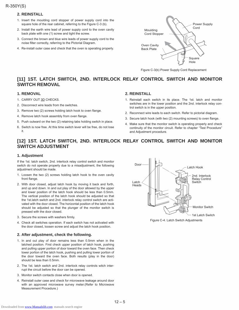
2. REINSTALL1. Insert the moulding cord stopper of power supply cord into the
square hole of the rear cabinet, referring to the Figure C-3 (b).
2. Install the earth wire lead of power supply cord to the oven cavityback plate with one (1) screw and tight the screw.
3. Connect the brown and blue wire leads of power supply cord to thenoise filter correctly, referring to the Pictorial Diagram.
4. Re-install outer case and check that the oven is operating properly.
Figure C-3(b) Power Supply Cord Replacement
[11] 1ST. LATCH SWITCH, 2ND. INTERLOCK RELAY CONTROL SWITCH AND MONITORSWITCH REMOVAL
1. REMOVAL1. CARRY OUT 3D CHECKS.
2. Disconnect wire leads from the switches.
3. Remove two (2) screws holding latch hook to oven flange.
4. Remove latch hook assembly from oven flange.
5. Push outward on the two (2) retaining tabs holding switch in place.
6. Switch is now free. At this time switch lever will be free, do not loseit.
2. REINSTALL1. Reinstall each switch in its place. The 1st. latch and monitor
switches are in the lower position and the 2nd. interlock relay con-trol switch is in the upper position.
2. Reconnect wire leads to each switch. Refer to pictorial diagram.
3. Secure latch hook (with two (2) mounting screws) to oven flange.
4. Make sure that the monitor switch is operating properly and checkcontinuity of the monitor circuit. Refer to chapter “Test Procedure”and Adjustment procedure.
[12] 1ST. LATCH SWITCH, 2ND. INTERLOCK RELAY CONTROL SWITCH AND MONITORSWITCH ADJUSTMENT
1. AdjustmentIf the 1st. latch switch, 2nd. interlock relay control switch and monitorswitch do not operate properly due to a misadjustment, the followingadjustment should be made.
1. Loosen the two (2) screws holding latch hook to the oven cavityfront flange.
2. With door closed, adjust latch hook by moving it back and forth,and up and down. In and out play of the door allowed by the upperand lower position of the latch hook should be less than 0.5mm.The vertical position of the latch hook should be adjusted so thatthe 1st.latch switch and 2nd. interlock relay control switch are acti-vated with the door closed. The horizontal position of the latch hookshould be adjusted so that the plunger of the monitor switch ispressed with the door closed.
3. Secure the screws with washers firmly.
4. Check all switches operation. If each switch has not activated withthe door closed, loosen screw and adjust the latch hook position.
2. After adjustment, check the following.1. In and out play of door remains less than 0.5mm when in the
latched position. First check upper position of latch hook, pushingand pulling upper portion of door toward the oven face. Then checklower portion of the latch hook, pushing and pulling lower portion ofthe door toward the oven face. Both results (play in the door)should be less than 0.5mm.
2. The 1st. latch switch and 2nd. interlock relay controls witch inter-rupt the circuit before the door can be opened.
3. Monitor switch contacts close when door is opened.
4. Reinstall outer case and check for microwave leakage around doorwith an approved microwave survey meter.(Refer to MicrowaveMeasurement Procedure.)
Figure C-4. Latch Switch Adjustments
Power SupplyCord
Oven CavityBack Plate
SquareHole
MouldingCord Stopper
Latch Hook
Monitor Switch
2nd. InterlockRelay ControlSwitch
1st Latch Switch
LatchHeads
Door
R-350Y(S)
Downloaded from www.Manualslib.com manuals search engine

12 – 6
[13] DOOR REPLACEMENT
1. REMOVAL1. Disconnect the power supply cord.
2. Open the door slightly.
3. Insert a putty knife (thickness of about 0.5mm) into the gapbetween the choke cover and door frame as shown in Figure C-5 tofree engaging parts.
4. Pry the choke cover by inserting a putty knife as shown Figure C-5.
5. Release choke cover from door panel.
6. Now choke cover is free.
NOTE: When carrying out any repair to the door, do not bend orwarp the slit choke (tabs on the door panel assembly) toprevent microwave leakage.
Figure C-5. Door Disassembly
7. Release two (2) pins of door panel from two (2) holes of upper andlower oven hinges by lifting up.
8. Now, door panel with door frame is free from oven cavity.
9. Remove the two (2) screws holding the door panel to door frame.
10.Release door panel from ten (10) tabs of door frame.
11.Now, door panel with sealer film is free.
12.Tear sealer film from door panel.
13.Now, door panel is free.
14.Slide latch head upward and remove it from door frame with releas-ing latch spring from door frame and latch head.
15.Now, latch head and latch spring are free.
16.Remove the two (2) door stoppers.
17.Remove door glass from door frame by sliding.
18.Now, door glass is free.
19.Remove the door decorations from the door frame by straighteningall tabs of the door decorations.
20.Now, the door frame is free.
2. REINSTALL1. Re-install door screen and door decoration to door frame.
2. Reinstall the latch spring to the latch head. Reinstall the latchspring to the door frame. Reinstall latch head to door frame.
3. Reinstall door panel to door frame by fitting ten (10)tabs of doorframe to ten (10) holes of door panel.
4. Hold the door panel to the door frame with the two (2) screws.
5. Put sealer film on door panel. Refer to “Sealer Film” about how tohandle new one.
6. Catch two (2) pins of door panel on two (2) hole of upper and loweroven hinges.
7. Re-install choke cover to door panel by pushing.
NOTE: After any service to the door;
1) Make sure that 1st. latch switch, 2nd. interlock relay control switchand monitor switch are operating properly. (Refer to chapter “TestProcedures”.).
2) An approved microwave survey meter should be used to assurecompliance with proper microwave radiation emission limitationstandards.
3. After any service, make sure of the following:1. Door latch heads smoothly catch latch hook through latch holes
and that latch head goes through center of latch hole.
2. Deviation of door alignment from horizontal line of cavity face plateis to be less than 1.0mm.
3. Door is positioned with its face pressed toward cavity face plate.
4. Check for microwave leakage around door with an approved micro-wave survey meter. (Refer to Microwave Measurement Procedure.)
NOTE: The door on a microwave oven is designed to act as anelectronic seal preventing the leakage of microwaveenergy from oven cavity during cook cycle. This functiondoes not require that door be air-tight, moisture (conden-sation)-tight or light-tight. Therefore, occasional appear-ance of moisture, light or sensing of gentle warm airmovement around oven door is not abnormal and do notof themselves, indicate a leakage of microwave energyfrom oven cavity.
Figure C-6. Door Replacement
4. SEALER FILM1. Put the adhesive tape on the backing film of the sealer film as
shown in Fig. C-7
2. Tear the backing film by pulling the adhesive tape.
3. Put the pasted side of the sealer film on the door panel
Figure C-7. Sealer film
Choke Cover
Door Frame
Putty Knife Pin
Pin
UpperOven Hinge
Upper OvenHinge
Lower OvenHinge
LowerOven Hinge
Slit choke ofdoor panel
Choke Cover
Sealer film Backing film
Adhesive tape
R-350Y(S)
Downloaded from www.Manualslib.com manuals search engine

13 – 1
CHAPTER 13. MICROWAVE MEASUREMENTAfter adjustment of door latch switches, monitor switch and door are completed individually or collectively, the following leakage test must be per-formed with a survey instrument and it must be confirmed that the result meets the requirements of the performance standard for microwave oven.
REQUIREMENT
The safety switch must prevent microwave radiation emission in excess of 5mW/cm2 at any point 5cm or more from external surface of the oven.
PREPARATION FOR TESTING
Before beginning the actual test for leakage, proceed as follows;
1. Make sure that the test instrument is operating normally as specified in its instruction booklet.
Important:
Survey instruments that comply with the requirement for instrumentations as prescribed by the performance standard for microwave ovens mustbe used for testing.
Recommended instruments are:
NARDA 8100
NARDA 8200
HOLADAY HI 1500
SIMPSON 380M
2. Place the oven tray into the oven cavity.
3. Place the load of 275 �15ml of water initially at 20 �5�C in the centre of the oven tray. The water container should be a low form of 600 ml beakerwith inside diameter of approx. 8.5cm and made of an electrically non-conductive material such as glass or plastic.
The placing of this standard load in the oven is important not only to protect the oven, but also to insure that any leakage is measured accurately.
4. Close the door and turn the oven ON with the timer set for several minutes. If the water begins to boil before the survey is completed, replace itwith 275ml of cool water.
5. Move the probe slowly (not faster that 2.5cm/sec.) along the gap.
6. The microwave radiation emission should be measured at any point of 5cm or more from the external surface of the oven.
Microwave leakage measurement at 5 cm distance
mW cm 2
mW cm 2
R-350Y(S)
Downloaded from www.Manualslib.com manuals search engine

14 – 1
CHAPTER 14. CIRCUIT DIAGRAMS
[1] Oven Schematic
Figure O-1 Oven Schematic-OFF Condition
Figure O-2 Oven Schematic-ON Condition
SCHEMATICNOTE: CONDITION OF OVEN1. DOOR CLOSED.2. CLOCK APPEARS ON DISPLAY.
SCHEMATICNOTE: CONDITION OF OVEN1. DOOR CLOSED.2. COOKING TIME PROGRAMMED.3. START KEY TOUCHED.
EA
RTH
BLU
BR
N
NE
UTR
AL
LIV
E
FUSEF10A
NL
230-
240V
50H
z
2.2μ
F/A
C25
0V
NO
ISE
SU
PP
RE
SS
ION
CO
IL
LIN
EB
YPA
SS
CA
PAC
ITO
RLI
NE
BY
PAS
SC
APA
CIT
OR
0.00
47μF
/AC
250V
0.00
47μF
/AC
250V
RY-1 RY-2 RY-3
F-3
F-2
F-1
TUR
NTA
BLE
MO
TOR
FAN
MO
TOR
OV
EN
LAM
P
MO
NIT
OR
SW
ITC
H
OL
FM TTM
MA
GN
ETR
ON
1ST. LATCHSWITCH
2ND. INTERLOCKRELAY CONTROLSWITCH
CONTROLUNIT
HUMIDITYSENSOR
INVERTERUNIT
A1A2A3
A1
C1C2C3
A7A5
A3 B1 B2
OVEN TEMP FUSE
NOISE FILTER UNIT
LIN
EC
RO
SS
CA
PAC
ITO
R
R-350Y(S)
Downloaded from www.Manualslib.com manuals search engine

14 – 2
[2] Pictorial Diagram (Figure S-1)
Figure S-1. Pictorial Diagram
CO
M.
N.O
.
2ND
.IN
TER
LOC
KR
ELA
YC
ON
TRO
LS
WIT
CH
GR
N
BLK
GR
N
GR
N
BLK
HU
MID
ITY
SE
NS
OR
RE
DW
HT
1 2 3
CN
-F
1 2G
RN
BLK
CN
-B
TEM
PE
RAT
UR
EFU
SE
(OV
EN
)
RE
DR
ED
WH
T
OV
EN
LAM
P
RE
D
PN
K
WH
T
WH
TFA
NM
OTO
R
TUR
NTA
BLE
MO
TOR
RE
D
WH
T
RE
D
MA
GN
ETR
ON
1ST.
LATC
HS
WIT
CH
CO
M.
NO
GR
Y
WH
T
BLU
WH
T
CO
M.
MO
NIT
OR
SW
ITC
H
N.C
.
WH
T
RE
D
WH
T
RE
D
WH
T
WH
T
BR
N
BLU
BLU
OR
G
WHT
123C
N-C
BLU
1 2R
ED
BLU RE
DR
ED
BLU
OR
G
WHT
123
1 2 3
PN
K
RE
D
4 5 6 7
BLK
GR
Y
CN
-A
BLK
RE
D
RE
D
Pow
erSu
pply
Cor
dO
ven
Cav
ityBa
ckPl
ate
Scre
w
G/Y
EA
RTH
AC
3M
BLU
RED 13
CN-A
F FA
INV
ER
TER
UN
IT
Inve
rterh
arne
ss
Hig
hvo
ltage
wire
asse
mbl
y
NO
TE:
Wire
with
case
shou
ldbe
conn
ecte
dto
FA.
HIG
HV
OLT
AG
EC
OM
PO
NE
NTS
CO
NTR
OL
UN
ITN
EU
TRA
L
LIV
E
R-350Y(S)
Downloaded from www.Manualslib.com manuals search engine
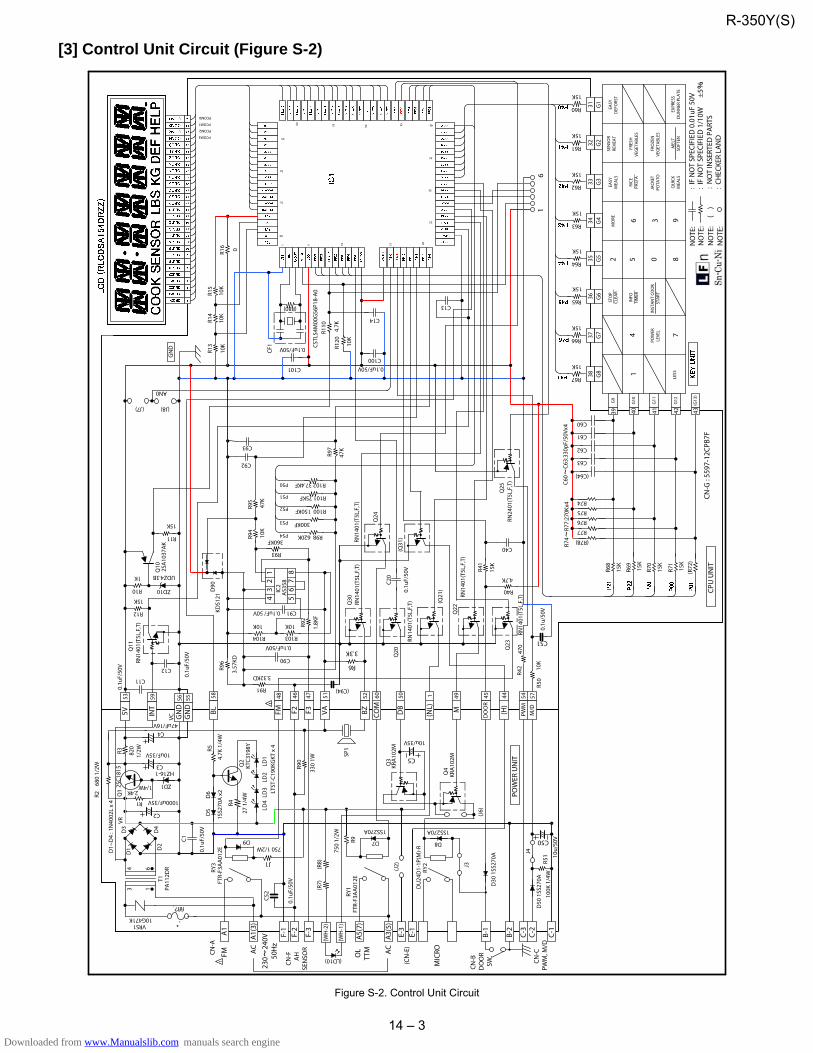
14 – 3
[3] Control Unit Circuit (Figure S-2)
Figure S-2. Control Unit Circuit
UDZ4.3B R68
15K
R69
15K
R70
15K
15K
R75
R74
(R72
)
C60
C61
C62
C63
(C64)
R74
R77:
270K
x4C6
0C6
3:33
0pF/
50Vx
4
GN
D
CPU
UN
IT
OL
TTM
MIC
RO
CN-B
DO
OR
SW.
R71
R77
R76
(R78)
0.1u
F/50
V
3132
3635
3433
3738R67
15K
R66
15K
R65
15K
R64
15K
R63
15K
R62
15K
R61
15K
R60
15K
F-1
F-2
F-3
R90
330
1W
R91
3.32KD
R92
1.8K
F
C90
0.1uF/50V
R94
10K
R95
47K
C91
D90
KDS1
21R9
6
3.57
KD
R97
Q30
A5(
7)
A3(
5)Q
20
D30
1SS
270A
C20
0.1u
F/50
V
R40
4.7KR4
1
15K
C40
B-1
CN-F AH
SE
NSO
R
B-2
C92
C93
(J8)
R11
15K
C14
Q10 2S
A10
37A
K
ZD10R10
1K
C13
R12
15K
C12
Q11
RN14
01(T
5L,F
,T)
C447uF/16V
C1
R30.
1uF/
50V
C11
C3
10uF/35V
C2
2SC1
815
Q1
ZD12.4K
HZ16-1
R2
R1
4.7K
1/4
W
KTC3
198YR5
Q2
R6
3.3K KR
A10
2M
10u/35V
C5
D5
D6
27 1
/4W
R4
D8
820
1/2W
1SS2
70A
x2
1SS270A
Q3
CSTL
S4M
00G
56P1
8-A
0
R98 620K
R100 150KF
R101 75KF
R102 37.4KF
R93
360KF
VRS110G471K
GN
D
5V INT
VA BZF2 F3
DO
OR
M
T1PA
112D
R
D1~
D4
: 1N
4002
L x
4 1000uF/35V
680
1/2W
1/4W
47K
Q4
1SS270A
SP1
RY1
RY2
DU
24D
1-1P
(M)-R
D7
AC
AC
0.1u
F/50
V
0.1uF/ 50V
POW
ER U
NIT
AN0
R13
10K
R14
10K
R15
10K
BL DB
P50
P51
P52
P53
P54
CF1
FTR-
F3A
A01
2E
(J7)
LD1
LD2
LD3
LD4
1
80
65
40
25
3 1
4 6
D1 D
2
D3
D4
LTST
-C19
0KG
KT x
4
CN-G
: 55
97-1
2CPB
7F
(R80)
5 10 15 20
30
35
45505560
70
75
R110
G1
G2
G3
G4
G5
G6
G7
G8
G9
G10
G11
G12
PCOM0
PCOM1
PCOM2
PCOM3
(WH
-2)
(WH
-1)
(LD10)
(R7)
(R8)
(NL)
(Q21
)
(G13
)
10K
R120
EASY
DEF
ORS
T
SEN
SOR
REH
EAT
INFO
TIM
ER
3
2
16
54 7
89
0PO
WER
LEVE
L
LESS
RICE
PAST
A
STO
PCL
EAR
FRES
HVE
GET
ABL
ES
MO
RE
QU
ICK
MEA
LS
JACK
ETPO
TATO
FRO
ZEN
VEG
ETA
BLES
EASY
MEA
LS
16
230
240V
50
Hz
VC
VR
4.7K
C-1
C-2
C-3
M/D
PWM
A1
A1(
3)
FM COM
10K
10u/
50V
0.1u
/50V
D50
1SS
270A
RN14
01(T
5L,F
,T)
RN14
01(T
5L,F
,T)
RN14
01(T
5L,F
,T)
Q24
Q22
Q23
Q25
RN24
01(T
5L,F
,T)
RY3
R9
J3
J1
J4
C50
C51
R50
CN-C
PWM
, M/D
C1000.1uF/50VC101
0.1uF/50V
R42
470
fifl?
FM
IC2
AS3
58
32
4 5
1
67
8
R104
10K
R103
10K
C52
0.1u
F/50
V
D9
NO
TE:
IF N
OT
SPEC
IFIE
D 1
/10W
±5
NO
TE:
NO
T IN
SERT
ED P
ART
S(
)N
OTE
:CH
ECKE
R LA
ND
NO
TE:
IF N
OT
SPEC
IFIE
D 0
.01u
F 50
V
KRA
102M
750
1/2W
(C94)
(J6)
R16 0
E-3
E-1
(H)
(J2)
(Q31
)
GN
D
CN-A
(CN
-E)
EXPR
ESS
DU
NN
ER P
LATE
MEL
TSO
FTEN
INST
AN
T CO
OK
STA
RT
RN14
01(T
5L,F
,T)
100K
1/4
WR5
1
FTR-
F3A
A01
2E
750 1/2W
1
57544445491506052514746481
5855565953
39 40 41 42 43
RN14
01(T
5L,F
,T)
300KF
R-350Y(S)
Downloaded from www.Manualslib.com manuals search engine

14 – 4
[4] Printed Wiring Board (Figure S-3)
Figure S-3. Printed Wiring Board of Power Unit
R-350Y(S)
Downloaded from www.Manualslib.com manuals search engine

14 – 5
[5] Inverter Unit Circuit (Figure S-4)
Figure S-4. Inverter unit circuit
1.:I
FNO
TS
PEC
IFIE
D1/
10W
J(±5
%)
2.:I
FNO
TS
PEC
IFIE
D1S
S133
or1S
S27
0A3.
()
:NO
TIN
SER
TPA
RTS
4.:C
HA
SSIS
EAR
TH
5.:V
EE
LEC
TRIC
POTE
NTI
AL
C100
35V
100u
C111
100
0V0.
12u
R113
39k
VRS1
10
M AC3
R118 10
R10
1.2K
1/2W
R115
1/2W
47k
CN-A123
R101
1/4W
3.3k
F
(R10
2)(V
R100
)
CT10
0
D100
VRS1
00
R100
15W
3.3K
cem
ent
ZD10
0
ZD10
1
ZD11
0R1
141/
2W47
k
R112
1/2W
47k
R111
1/2W
39k
R117
240
F FAD1
10
R11
01/
2W13
0k
R10
91/
2W15
0k
L110
C110
400V
3.9u
Q11
0
R11
91/
2W10
0k
R11
61/
2W10
0k
5 6
8 7 1 2
(VRS
111)
T110
P1 P2
F FA H1 H2
D120
D121
C12
028
00V
3000
p
C12
131
00V
4800
p
R120
120M
±20%
1.3W
TH11
1
J101
200
(R10
3)
ZD10
#187
#187
#250
#250
R121
2W2.
2
R122
2W2.
2
1 2
4 3
PD10
0
R12
3R1
241K
1K
9.4Vx2
5.1V
27V
CONT
ROL
CIRC
UIT
R-350Y(S)
Downloaded from www.Manualslib.com manuals search engine

14 – 6
R-350Y(S)
Downloaded from www.Manualslib.com manuals search engine

PARTS LIST
CONTENTS
This document has been published to be usedfor after sales service only.The contents are subject to change without notice.
HOW TO ORDER REPLACEMENT PARTSTo have your order filled promptly and correctly, pleasefurnish the following information.
1. MODEL NUMBER2. REF. NO.3. PART NO.4. DESCRIPTION
Parts marked "*" may cause undue microwave exposure.Parts marked " " are used in voltage more than 250V.
MICROWAVE OVEN
MODELS R-350Y(S)R-350Y(W)
SPADPA204WRE0
FPADBA541WRKZ
SSAKHA034WRE0
SPAKCF221WREZ [R-350Y(S)]SPAKCF223WREZ [R-350Y(W)]
FPADBA542WRKZ
(CPADBA317WRKZ)
6-6
6-2
6-1
CABINET COVERSPAKHA011WRE0
DOOR PROTECTION SHEET
TOP PAD ASSEMBLY
PLASTIC BAG
BOTTOM PAD ASSEMBLY
INSTRUCTION BOOK
TURNTABLE TRAY
TURNRTABLE SUPPORT
INTO THEOVEN CAVITY
PACKING CASE
TRAY PAD ASSY
Not replaceable items.
SPAKHA012WREZ
FOAM SHEET
PartsGuide
[1] OVEN PARTS
[]
[2] DOOR AND CONTROL PANEL PARTS
INDEX
R-350Y(S)
Downloaded from www.Manualslib.com manuals search engine

2
[1] OVEN PARTS
7-2
7-1
4-1
4-5
4-4
6-3
7-3
4-3
4-9
4-12
2-1
1-7
7-3
1-9
4-10
7-2
7-4
7-6
4-12
1-1
1-1
1-11
7-7
7-107-10
7-7
7-5
7-8
7-1
1-13
1-127-2
7-2
7-10
7-10
7-10
7-1
7-8
4-8
1-8
7-8
1-2
2-3
2-2
4-14
4-18
4-19
4-16
1-3
4-15
1-6
6-1
6-24-7 6-5
2-3
2-3
2-3
4-12
7-6
4-231-15
7-114-24
4-25
4-17
7-10
7-10
1-4
4-2
7-10
7-8
7-8
4-11
7-9
R-350Y(S)
Downloaded from www.Manualslib.com manuals search engine

R-350Y(S)
3
NO. PARTS CODE PRICE RANK
NEW MARK
PART RANK DESCRIPTION
[1] OVEN PART
1-1 QSW-MA147WRZZ AG 1st.latch/ 2nd.interlock relay control switch (Micro switch a) 1-1 QSW-MA085WRE0 AF 1st.latch/ 2nd.interlock relay control switch (Micro switch a Interchangeable) 1-1 QSW-MA137WRE0 AH 1st.latch/ 2nd.interlock relay control switch (Micro switch a Interchangeable) 1-2 QSW-MA148WRZZ AF Monitor switch (Micro switch b) 1-2 QSW-MA086WRE0 AF Monitor switch (Micro switch b Interchangeable) 1-2 QSW-MA138WRE0 AH Monitor switch (Micro switch b Interchangeable) 1-3 QACC-A178WRZZ AQ Power supply cord 1-3 QACC-A156WRZZ AQ Power supply cord (Interchangeable) 1-3 QACC-A139WRZZ AQ Power supply cord (Interchangeable) 1-3 QACC-A180WRZZ AQ Power supply cord (Interchangeable) 1-4 DPWBFC625WRKZ BQ Inverter unit 1-6 RMOTEA450WRZZ AV Fan motor 1-6 RMOTEA405WRZZ AX Fan motor (Interchangeable) 1-6 RMOTEA450WRZZ AV Fan motor (Interchangeable) 1-6 RMOTEA475WRZZ AX Fan motor (Interchangeable) 1-7 QFS-TA014WRE0 AG Temperature fuse 150A(oven) (Temp. Fuse 150H) 1-8 RLMPTA088WRZZ AN Oven lamp 1-8 RLMPTA083WRZZ AM Oven lamp (Interchangeable) 1-8 RLMPTA101WRZZ AM Oven lamp (Interchangeable) 1-9 RMOTDA302WRZZ AN Turntable motor 1-9 RMOTDA253WRZZ AV Turntable motor (Interchangeable) 1-9 RMOTDA289WRZZ AQ Turntable motor (Interchangeable) 1-9 RMOTDA173WRE0 AX Turntable motor (Interchangeable) 1-9 RMOTDA299WRZZ BE Turntable motor (Interchangeable)
* 1-11 RV-MZA381WRZZ BG Magnetron 1-12 FPWBFA461WRKZ AT Noise filter unit 1-13 QFS-CA026WRZZ AH Fuse f10a 1-15 FDTCTA230WRKZ AX Humidity sensor
2-1 GCABUA935WRPZ BD Outer case cabinet [R-350Y(S)] 2-1 GCABUA883WRPZ BF Outer case cabinet [R-350Y(W)] 2-2 GDAI-A489WRWZ AS Bottom plate 2-3 GLEGPA074WRE0 AC Leg
4-1 PHOK-A131WRFZ AL Latch hook 4-2 LANGQA841WRPZ AH Inverter angle 4-3 NFANJA053WRFZ AG Fan blade 4-4 FOVN-A693WRTZ Oven cavity assy 4-5 MLEVPA233WRF0 AG Switch lever 4-7 FCOVPA083WRKZ AF Wg cover assy 4-8 PDUC-A833WRPZ AM Air duct 4-9 PDUC-A854WRPZ AL Fan duct 4-10 PPACGA176WREZ AC Ttm packing 4-11 PDUC-B224WRPZ AG Lower fan duct 4-12 PCUSUA278WRP0 AB Mg cushion 4-14 PCUSGA614WRPZ AE Cushion 4-15 PCUSGA615WRPZ AE Cushion 4-16 MROD-A019WREZ AN Chassis support 4-17 PCUSUA313WRP0 AF Cushion 4-18 PCUSGA620WRPZ AF Cushion 4-19 PSPAJA007WRFZ AF Spacer 4-23 PDUC-A842WRPZ AP Sensor duct 4-24 PCUSGA388WRP0 AK Rubber cushion 4-25 PCUSUA212WRP0 AB Cushion
6-1 FROLPA101WRKZ AR Roller assy 6-2 NTNT-A117WREZ AS Turntable 6-3 TCAUHA343WRRZ AF Micro caution 6-5 TLABMB405WRRZ AF Menu label
7-1 XHPS740P08K00 AB Screw : 4mm x 8mm 7-2 XOTS740P12RV0 AD Screw : 4mm x 12mm 7-3 LX-CZA073WRE0 AC Special screw 7-4 LX-CZ0052WRE0 AA Special screw 7-5 XOTS740P08000 AA Screw : 4mm x 8mm 7-6 XETS740P10000 AA Screw : 4mm x 10mm 7-7 XHPS740P08000 AB Screw : 4mm x 8mm 7-8 XHTS740P08RV0 AG Screw : 4mm x 8mm 7-9 XHTS740P08000 AC Screw : 4mm x 8mm 7-10 XOTS740P08000 AA Screw : 4mm x 8mm 7-11 XHPS730P06000 AB Screw : 3mm x 6mm
ELECTRIC PARTS
CABINET PARTS
OVEN PARTS
MISCELLANEOUS
SCREWS
Downloaded from www.Manualslib.com manuals search engine

4
[2] DOOR AND CONTROL PANEL PARTS
Actual wire harness may be different from illustration.
1-14
6-6
1-5
1-10
5-6
5-5
5-3
5-2
5-1
5-10
5-8
5-9
5-7
5-4
5-11
3-4
3-5
3-33-2
3-8
3-9
3-7
3-7
3-1
R-350Y(S)
Downloaded from www.Manualslib.com manuals search engine

R-350Y(S)
5
NO. PARTS CODE PRICE RANK
NEW MARK
PART RANK DESCRIPTION
[2] DOOR AND CONTROL PANEL PARTS
1-5 FW-QZA130WRKZ AH High voltage wire assembly1-10 FW-VZC337WREZ AG Inverter harness 1-14 FW-VZC336WREZ AW Main wire harness
3-1 DPWB-B044DRKZ BE Control unit 3-2 PSHEPB587WREZ AK Graphic sheet 3-3 QSW-KA061DRZZ AQ Membrane switch 3-4 JBTN-B631WRTZ AM Open button R-350Y(S) 3-4 JBTN-B630WRFZ AG Open button R-350Y(W) 3-5 MSPRCA050WRE0 AB Button spring 3-7 XEPS730P08XS0 AB Screw : 3mm x 8mm 3-8 HPNLCC346WRTZ AW Control panel R-350Y(S) 3-8 HPNLCC345WRFZ AT Control panel R-350Y(W) 3-9 HDECQA465WRFZ AG Panel cap right
* 5-1 FDORFA403WRTZ BF Door panel 5-2 PSHEPA382WRE0 AH Sealer film
* 5-3 GWAKPB432WRRZ AT Door frame R-350Y(S) * 5-3 GWAKPB428WRRZ AT Door frame R-350Y(W)
5-4 HDECQA464WRFZ AG Door sash * 5-5 LSTPPA188WRF0 AG Latch head
5-6 MSPRTA187WRE0 AC Spring * 5-7 GCOVHA450WRFZ AG Choke cover
5-8 LSTPPA318WRFZ AF Glass stoper R 5-9 LSTPPA319WRFZ AF Glass stoper L 5-10 PGLSPA811WREZ AX Front door glass 5-11 XEPS740P08000 AB Front door glass
6-6 TINSEB318WRRZ AN Instruction book
CONTROL PANEL PARTS
DOOR PARTS
MISCELLANEOUS
ELECTRIC PARTS
Downloaded from www.Manualslib.com manuals search engine

EndPage
COPYRIGHT © 2011 BY SHARP CORPORATION
ALL RIGHTS RESERVED.
No part of this publication may be reproduced, stored
in retrieval systems, or transmitted in anyform or by
any means, electronic, mechanical, photocopying, re-
cording, or other wise, without prior written permission
of the publisher.
Downloaded from www.Manualslib.com manuals search engine