Embed Size (px)
Citation preview

TOPJOB® S – Sensor/Actuator Terminal Blocks with Push-in CAGE CLAMP® Reliability

2
TOPJOB® S – SEND THE RIGHT SIGNALS.
TWO IN ONE.
TOPJOB® S – Sensor/Actuator Terminal Blocks with Push-in CAGE CLAMP® Reliability
WITH ALL OPTIONS COVERED.
For the Highest Signal Density
• Pack several sensors into the smallest possible space using only 3.5 mm per sensor on the DIN-rail
• Suitable for small terminal boxes within a system’s decentralized periphery, as well as for centralized installation in the switch cabinet
Range of Multifunctional Jumpers
• Commoning with standard jumpers – no pole number limitation
• Color-coded jumpers simplify potential assignment

3
TOPJOB® S – SEND THE RIGHT SIGNALS.
Fastest Marking System
• Clear identification thanks to multi-line marking strips that don’t cover the jumper slot
• Easy to read from any angle thanks to two marker slots on the top and side of the terminal strip
LED, Wiring and Marking in Plain View
• Indicator LEDs, jumpers and markers are always visible – even when wired
• Streamlined terminal block design provides quick wiring overview and a simplified control layout
KEEP YOUR COSTS IN LINE. KEEP SAFETY IN SIGHT.

4
FOR THE HIGHEST SIGNAL DENSITY
Potential Levels
• Power supply and, if necessary, sensor grounding or shielding of the sensors/actuators is performed on the potential levels
• Each level has two connections per current bar • Commoning is possible without pole
number limitation
The sensor/actuator terminal blocks feature several potential levels and one signal level. The potential levels are for power supply and, if necessary, sensor grounding or shielding; the signal level is for switching signal trans- mission from the sensors or to the actuators.
Signal Level
• The signal level transmits switching signals from two sensors or to the actuators, sepa- rately per terminal block – in a single housing
A single terminal block housing accommo- dates two interconnected potential terminals with doubled spacing on the lower levels and two independent signal pathways with single spacing of 3.5 mm on the upper levels.
Two separate current bars
Signal Level
Potential Levels
One doubled current bar on each level

5
RANGE OF MULTIFUNCTIONAL JUMPERSWhen using TOPJOB® S Sensor/Actuator Terminal Blocks, standard 2000 Series Jumpers provide the right solution for all commoning tasks.
These jumpers can be universally used on both potential levels and the signal level.
On the potential levels, standard jumpers can be used for commoning with no pole number limitation. Each terminal block has two connected clamping units and thus two connected jumper slots. This allows any number of terminal blocks to be commoned in just one jumper slot using jumpers with even pole numbers.
For sensor/actuator terminal blocks without ground connection to the DIN-rail, the ground connection can also be performed economi- cally by commoning to the terminal block with a ground foot (e.g., via the supply terminal block).
Two jumper slots are available on the signal level for commoning with standard jumpers. This level features two independent signal pathways. Terminal block versions with an LED have only one jumper slot for testing or commoning.
Orange supply terminal blocks with the same profile can be placed anywhere within an assembly. They are available in cross sections up to 4 mm2 (12 AWG). Power supply can be performed either via center feed or ring feed configuration.
Commoning Potential Levels
Ground Commoning
Commoning Signal Level
Power Supply

6
FASTEST MARKING SYSTEM
Marking Strips
Marking Levels
WMB Markers
Marker Carrier
TOPJOB® S Sensor/Actuator Terminal Blocks can be marked in multiple ways. Marking strips (2009-110) offer the fastest and easiest possi-bility. Multi-line marking simplifies the labeling of a terminal block’s function, allowing individual signals and groups to be simultaneously marked.
Marking using 3.5 mm WMB markers is also possible. They are available as WMB Inline markers on a reel (2009-113) and as WMB marking cards (793-35xx).
TOPJOB® S Sensor/Actuator Terminal Blocks can be marked on the top and on the side, without covering the jumper slot.
A pivoting marker carrier (2000-121) can be snapped in as a retrofit for additional marking levels.

7
LED, WIRING AND MARKING IN PLAIN VIEWTOPJOB® S Sensor/Actuator Terminal Blocks provide a fast overview – even when wired. Both a center LED, as well as commoning and marking on the signal level quickly tell you what you need to know.
• The streamlined terminal block design, as well as colored conductor entries and jumpers provide quick wiring overview and a simplified control layout.
• LEDs, jumpers and markers are always visible – even when wired.

8
3-Conductor Sensor Terminal Blocks 1 (1.5) mm2, 2000 Series
0.14 … 1 (1.5) mm2 1 24 … 16 AWG250 V/4 kV/3 2 300 V, 10 AIN 13.5 ATerminal block width: 7 mm / 0.276 in. 3L 9 … 11 mm / 0.39 in. 4
0.14 … 1 (1.5) mm2 1 24 … 16 AWG24 VDC 24 VDC, 10 AIN 13.5 ATerminal block width: 7 mm / 0.276 in. 3L 9 … 11 mm / 0.39 in. 4
2000-5311 2000-5311/1102-950 2000-5311/1101-951
S1 S1
S2 S2
S1 S1
S2 S2 S2 S2
S1 S1
Item No. Pack. Unit Item No. Pack. Unit3-conductor sensor terminal block 3-conductor sensor LED terminal block,
for PNP (high-side) switching sensors, yellow LED
gray 2000-5311 50 gray 2000-5311/1102-950 50
3-conductor sensor LED terminal block, for NPN (low-side) switching sensors, yellow LED
gray 2000-5311/1101-951 50
2000-5372/1102-953 2000-5372 2000-5352/1102-953 2000-5352
Item No. Pack. Unit Item No. Pack. Unit3-conductor sensor LED supply terminal block, 3-conductor sensor LED supply terminal block, 24 VDC, green LED 24 VDC, green LED, control panel side: 2.5 (4) mm2, max. 28 A
orange 2000-5372/1102-953 15 orange 2000-5352/1102-953 15
3-conductor sensor supply terminal block, 3-conductor sensor supply terminal block, max. 250 V, internal commoning max. 250 V, control panel side: 2.5 (4) mm2, max. 28 A
orange 2000-5372 15 orange 2000-5352 15
9
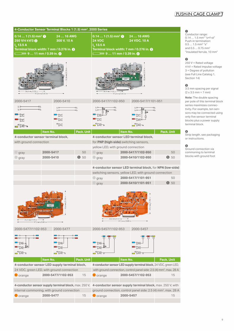
4-Conductor Sensor Terminal Blocks 1 (1.5) mm2, 2000 Series
0.14 … 1 (1.5) mm2 1 24 … 16 AWG250 V/4 kV/3 2 300 V, 10 AIN 13.5 ATerminal block width: 7 mm / 0.276 in. 3L 9 … 11 mm / 0.39 in. 4
0.14 … 1 (1.5) mm2 1 24 … 16 AWG24 VDC 24 VDC, 10 AIN 13.5 ATerminal block width: 7 mm / 0.276 in. 3L 9 … 11 mm / 0.39 in. 4
2000-5417 2000-5410 2000-5417/1102-950 2000-5417/1101-951
PE
S1 S1
S2 S2
PE
S1 S1
S2 S2
PE
S1 S1
S2 S2
PE
S2 S2
S1 S1
Item No. Pack. Unit Item No. Pack. Unit4-conductor sensor terminal block, 4-conductor sensor LED terminal block, with ground connection for PNP (high-side) switching sensors,
yellow LED, with ground connection gray 2000-5417 50 gray 2000-5417/1102-950 50 gray 2000-5410 5 50 gray 2000-5410/1102-950 5 50
4-conductor sensor LED terminal block, for NPN (low-side)switching sensors, yellow LED, with ground connection
gray 2000-5417/1101-951 50 gray 2000-5410/1101-951 5 50
2000-5477/1102-953 2000-5477 2000-5457/1102-953 2000-5457
PE PE PE
PE
PE
PE
Item No. Pack. Unit Item No. Pack. Unit4-conductor sensor LED supply terminal block, 4-conductor sensor LED supply terminal block, 24 VDC, green LED,24 VDC, green LED, with ground connection with ground connection, control panel side: 2.5 (4) mm2, max. 28 A
orange 2000-5477/1102-953 15 orange 2000-5457/1102-953 15
4-conductor sensor supply terminal block, max. 250 V, 4-conductor sensor supply terminal block, max. 250 V, with internal commoning, with ground connection ground connection, control panel side: 2.5 (4) mm2, max. 28 A
orange 2000-5477 15 orange 2000-5457 15
1 Conductor range: 0.14 … 1.5 mm2 “s+f-st” Push-in termination: 0.5 … 1.5 mm2 “s” and 0.5 … 0.75 mm2 “insulated ferrule, 10 mm” 2
250 V = Rated voltage 4 kV = Rated impulse voltage 3 = Degree of pollution (see Full Line Catalog 1, Section 14) 3 3.5 mm spacing per signal (2 x 3.5 mm = 7 mm)
Note: The double spacing per pole of this terminal block series maximizes connec- tivity. For example, ten sen-sors may be connected using only five sensor terminal blocks plus a power supply terminal block. 4 Strip length, see packaging or instructions. 5 Ground connection via commoning to terminal blocks with ground foot

10
3-Conductor Actuator Terminal Blocks 1 (1.5) mm2, 2000 Series
0.14 … 1 (1.5) mm2 1 24 … 16 AWG250 V/4 kV/3 2 300 V, 10 AIN 13.5 ATerminal block width: 7 mm / 0.276 in. 3L 9 … 11 mm / 0.39 in. 4
0.14 … 1 (1.5) mm2 1 24 … 16 AWG24 VDC 24 VDC, 10 AIN 13.5 ATerminal block width: 7 mm / 0.276 in. 3L 9 … 11 mm / 0.39 in. 4
2000-5317/102-000 2000-5310/101-000 2000-5317/1102-950 2000-5310/1101-951
PE
S1 S1
S2 S2
PE
S1 S1
S2 S2
PE
S1 S1
S2 S2
PE
S1 S1
S2 S2
Item No. Pack. Unit Item No. Pack. Unit3-conductor actuator terminal block, for PNP (high-side) 3-conductor actuator LED terminal block, for PNP (high-side)switching actuators, with ground connection switching actuators, yellow LED, with ground connection
gray 2000-5317/102-000 50 gray 2000-5317/1102-950 50 gray 2000-5310/102-000 5 50 gray 2000-5310/1102-950 5 50
3-conductor actuator terminal block, for NPN (low-side) 3-conductor actuator LED terminal block, for NPN (low-side)switching actuators, with ground connection switching actuators, yellow LED, with ground connection
gray 2000-5317/101-000 50 gray 2000-5317/1101-951 50 gray 2000-5310/101-000 5 50 gray 2000-5310/1101-951 5 50
2000-5377/102-000 2000-5377/101-000 2000-5357/102-000 2000-5357/101-000
PE
PEPE
PE
PE PE
PE
PE
PE
PE
Item No. Pack. Unit Item No. Pack. Unit3-conductor actuator supply terminal block, 3-conductor actuator supply terminal block, max. 250 V,max. 250 V, for PNP (high-side) switching actuators, control panel side: 2.5 (4) mm2, max. 28 A, for PNP (high-side)with ground connection, internal commoning switching actuators, with ground connection
orange 2000-5377/102-000 15 orange 2000-5357/102-000 153-conductor actuator supply terminal block, max. 250 V, 3-conductor actuator supply terminal block, max. 250 V,for NPN (low-side) switching actuators, with ground connection control panel side: 2.5 (4) mm2, max. 28 A, for NPN (low-side)
switching actuators, with ground connection orange 2000-5377/101-000 15 orange 2000-5357/101-000 15

11
End Plates Item No. Pack. UnitEnd and intermediate plates, 1 mm thick
for 3-conductor terminal blocks gray 2000-5391 100 (4x25)
for 4-conductor terminal blocks gray 2000-5491 100 (4x25)
AccessoriesJumpers Item No. Pack. UnitPush-in type jumper bars, insulated
IN 14 A, light gray2-pole 2000-402 200 (8x25)3-pole 2000-403 200 (8x25)⋮ ⋮ ⋮10-pole 2000-410 100 (4x25)
red …/000-005 blue …/000-006 yellow-green …/000-018
Push-in type jumper bars, insulatedIN 14 A, light gray1 to 3 2000-433 200 (8x25)1 to 4 2000-434 200 (8x25)⋮ ⋮ ⋮1 to 10 2000-440 100 (4x25)
Push-in type wire jumpers, insulatedIN 9 A, 0.75 mm2 conductor cross-sectionL = 60 mm 2009-402 100 (10x10)L = 110 mm 2009-404 100 (10x10)L = 250 mm 2009-406 100 (10x10)
Marking Item No. Pack. UnitDouble-deck marker carrier,
pivoting gray 2000-121 50 (2x25)
Marking strip, plain,11 mm wide, 50 m roll
white 2009-110 1
WMB Inline, plain,2,300 WMB markers (3.5 mm) on roll
white 2009-113 1
WMB Multi Marking System, plain10 strips with 10 markers per cardfor 3.5 mm terminal block width
white 793-3501 5smartPRINTER
258-5000 1More information at www.wago.com/printer
Carrier Rails Item No. Pack. UnitCarrier rails, steel
IN 76 A (reference length of 1 m)35 x 7.5 mm, 1 mm thick, 2 m longunslotted 210-113 10slotted 210-112 10 (10x1)Hole width: 25 mm; hole spacing: 36 mmslotted 210-115 1Hole width: 18 mm; hole spacing: 25 mm
Carrier rail, aluminumIN 76 A (reference length of 1 m)35 x 8.2 mm, 1.6 mm thick, 2 m longunslotted 210-196 10
End stops Item No. Pack. Unitfor DIN-35 rails6 mm wide 249-116 100 (4x25)10 mm wide 249-117 50 (2x25)
Testing Accessories Item No. Pack. UnitTesting tap
for max. 2.5 mm2
gray 2009-182 100 (4x25)
Test plug adapterfor 4 mm Ø test pluggray 2009-174 100 (4x25)
Banana plugsfor 4 mm Ø socket,color mixed
215-111 50
Tools Item No. Pack. Unit“Quickstrip 10” wire stripper
206-124 1
“Variocrimp 4” crimping tool0.25 ... 4 mm2
206-204 1
Insulated ferrules, extra long,0.5 mm2 216-241 10000.75 mm2 216-242 1000
For 2.5 (4) mm2 supply terminal blocks:1 mm2 216-243 10001.5 mm2 216-244 10002.5 mm2 216-246 1000
Operating tool with a partially insulated shaft,type 1, (2.5 x 0.4) mm blade
210-719 1

12
For the very first time, sensor/actuator wiring is pluggable between terminal box and switch cabinet thanks to the newest additions of WAGO’s TOPJOB® S terminal block family.
Both power supply and all signal paths can be combined into one single pluggable connector within a terminal box. Systems can be modularized via pre-assembled connectors.
WITH A PLUGGABLE SIGNAL LEVEL
Prevent wiring errors
via pluggable connectors that can be coded
Safely remove female plugs
via strain-relieved conductorsSecure female plugs
via locking levers
Faster and easier connections
via pre-assembled connectors

13
WITH A PLUGGABLE SIGNAL LEVEL
Assembly/Disassembly
The sensor/actuator terminal blocks with pluggable signal levels can be snapped together.
Assembly: Snap individual terminal blocks onto the DIN-rail and slide together.
Disassembly: Separate individual terminal blocks and slide laterally using an operating tool.
Mechanical Protection
Locking levers for female plugs provide additional safety, making accidental disconnection more difficult.
Furthermore, strain relief plates allow female plugs to be safely pulled out.
Mismating Protection
Before installation, the pluggable connectors may be coded to prevent wiring errors.
Coding: Insert a coding pin into the appropriate terminal block slot and break it off from the carrier.
Remove a coding finger from the female plug using a cutting tool.

14
3-/4-Conductor Sensor Terminal Blocks 1 (1.5) mm², 2020 Series
0.14 … 1.5 mm² 1 24 … 16 AWG250 V/4 kV 2 IN 13.5 ATerminal block width: 7 mm / 0.276 inch 3L 9 … 11 mm / 0.35 … 0.43 inch 4
0.14 … 1.5 mm² 1 24 … 16 AWG250 V/4 kV 2 IN 13.5 ATerminal block width: 7 mm / 0.276 inch 3L 9 … 11 mm / 0.35 … 0.43 inch 4
2020-5311 2020-5311/1102-950 2020-5417 2020-5417/1102-950S1 S1
S2 S2
S1 S1
S2 S2
PE
S1 S1
S2 S2
PE
S1 S1
S2 S2
Item No. Pack. Unit Item No. Pack. Unit3-conductor sensor terminal block, 4-conductor sensor terminal block, with pluggable signal level with ground connection, with pluggable signal level
gray 2020-5311 50 gray 2020-5417 50
3-conductor sensor LED terminal block, 4-conductor sensor LED terminal block,for PNP (high-side) switching sensors, for PNP (high-side) switching sensors, 24 VDC, yellow LED, 24 VDC, yellow LED, with pluggable signal level with ground connection, with pluggable signal level
gray 2020-5311/1102-950 50 gray 2020-5417/1102-950 50
2020-5372/1102-953 2020-5372 2020-5477/1102-953 2020-5477
PE PE
Item No. Pack. Unit Item No. Pack. Unit3-conductor sensor LED supply terminal block, 4-conductor sensor LED supply terminal block,24 VDC, green LED, with pluggable signal level 24 VDC, green LED, with ground connection,
with pluggable signal level orange 2020-5372/1102-953 15 orange 2020-5477/1102-953 15
3-conductor sensor supply terminal block, 4-conductor sensor supply terminal block,internally commoned, with pluggable signal level internally commoned, with ground connection
with pluggable signal level orange 2020-5372 15 orange 2020-5477 15
1 Conductor range: 0.14 … 1.5 mm² “s+f-st” Push-in termination: 0.5 … 1.5 mm² “s” and 0.5 … 0.75 mm² “insulated ferrules, 10 mm”
2
250 V = Rated voltage4 kV = Rated surge voltage3 = Degree of pollution (see Full Line Catalog 1, Section 14)
3
3.5 mm spacing per signal (2 x 3.5 mm = 7 mm)
Note: The double spacing per pole of this terminal block series maximizes connectivity. For example, ten sensors may be connected using only five sensor terminal blocks plus a power supply terminal block.
4
Strip length, see packaging or instructions
5
Ground connection via commoning to terminal blocks with ground foot
15
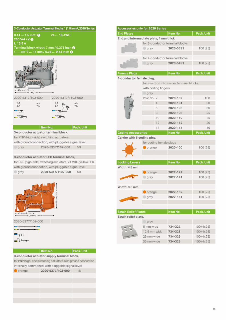
3-Conductor Actuator Terminal Blocks 1 (1.5) mm², 2020 Series
0.14 … 1.5 mm² 1 24 … 16 AWG250 V/4 kV 2 IN 13.5 ATerminal block width: 7 mm / 0.276 inch 3L 9 … 11 mm / 0.35 … 0.43 inch 4
2020-5317/102-000 2020-5317/1102-950
PE
S1 S1
S2 S2
PE
S1 S1
S2 S2
Item No. Pack. Unit3-conductor actuator terminal block,for PNP (high-side) switching actuators,with ground connection, with pluggable signal level
gray 2020-5317/102-000 50
3-conductor actuator LED terminal block,for PNP (high-side) switching actuators, 24 VDC, yellow LED, with ground connection, with pluggable signal level
gray 2020-5317/1102-950 50
2020-5377/102-000
PE
PEPE
Item No. Pack. Unit3-conductor actuator supply terminal block,for PNP (high-side) switching actuators, with ground connectioninternally commoned, with pluggable signal level
orange 2020-5377/102-000 15
Accessories only for 2020 SeriesEnd Plates Item No. Pack. UnitEnd and intermediate plate, 1 mm thick
for 3-conductor terminal blocks gray 2020-5391 100 (25)
for 4-conductor terminal blocks gray 2020-5491 100 (25)
Female Plugs Item No. Pack. Unit1-conductor female plug,
for insertion into carrier terminal blocks, with coding fingers
grayPole No. 2 2020-102 100
4 2020-104 506 2020-106 508 2020-108 2510 2020-110 2512 2020-112 2014 2020-114 10
Coding Accessories Item No. Pack. UnitCarrier with 6 coding pins,
for coding female plugs orange 2020-100 100 (25)
Locking Levers Item No. Pack. UnitWidth: 4.8 mm
orange 2022-142 100 (25) gray 2022-141 100 (25)
Width: 9.6 mm orange 2022-152 100 (25) gray 2022-151 100 (25)
Strain Relief Plates Item No. Pack. UnitStrain relief plate,
gray6 mm wide 734-327 100 (4x25)12.5 mm wide 734-328 100 (4x25)25 mm wide 734-329 100 (4x25)35 mm wide 734-326 100 (4x25)

0888
-017
7/01
00-6
901
– TJ
S IN
ITIA
TORE
N/A
KTO
REN
BRO
SCH
ÜRE
1.0
US –
11/
2017
– P
rinte
d in
Ger
man
y –
Subj
ect t
o de
sign
cha
nges
WAGO Kontakttechnik GmbH & Co. KGPostfach 2880 · 32385 MindenHansastraße 27 · 32423 [email protected]
Headquarters +49 571/ 887 - 0Sales +49 571/ 887 - 222Orders +49 571/ 887 - 44 333Fax: +49 571/ 887 - 844 169
WAGO is a registered trademark of WAGO Verwaltungsgesellschaft mbH.“Copyright – WAGO Kontakttechnik GmbH & Co. KG – All rights reserved. The content and structure of the WAGO websites, catalogs, videos and other WAGO media are subject to copy-right. Distribution or modification to the contents of these pages and videos is prohibited. Furthermore, the content may neither be copied nor made available to third parties for commer-cial purposes. Also subject to copyright are the images and videos that were made available to WAGO Kontakttechnik GmbH & Co. KG by third parties.”