Embed Size (px)
DESCRIPTION
Single phase
Citation preview
By
ABDUL HAKIM HJ ABU BAKAR
Topic 5:
FUNDAMENTAL OF FUNDAMENTAL OF
ELECTRICAL & ELECTRONICSELECTRICAL & ELECTRONICS
CLB 10402CLB 10402

Objective
After this lesson, student should be able to :
Understand the concept of peak, rms,
and average value
Understand the concept of shape factor
and peak factor
Objective
Peak value
2PP PV V
2PP PI I

peakV
peak to peakV

Root-mean-square (r.m.s) value
0.707rms PV V
0.7071rms PI I

• Average heating effect over half – cycle :
2
2/ 2 ( ) 1
( )( ) 2
P
P
I R watt radianI R watt
rad
• If I is the value of dc voltage through the same resistance to produce the same heating effect :
therefore
2 21
2rms PI R I R
0.70712
Prms P
II I
Average value
0.637avg PV V
0.637avg PI I
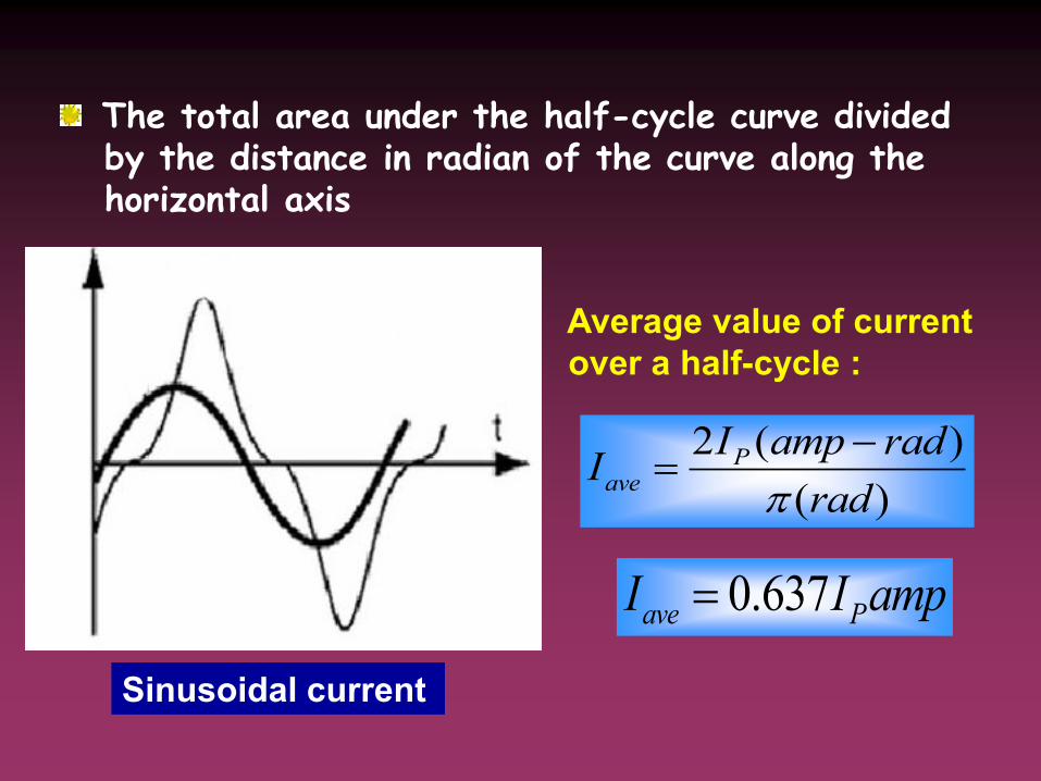
Sinusoidal current
2 ( )
( )
Pave
I amp radI
rad
Average value of current
over a half-cycle :
0.637ave PI I amp
The total area under the half-cycle curve divided by the distance in radian of the curve along the horizontal axis

The voltage across the resistor is directly proportional to the current It follows that the relationship derived for current
also apply to voltage So, in general, average value of sinusoidal current or voltage is
0.637ave PI I
0.637 x maximum value

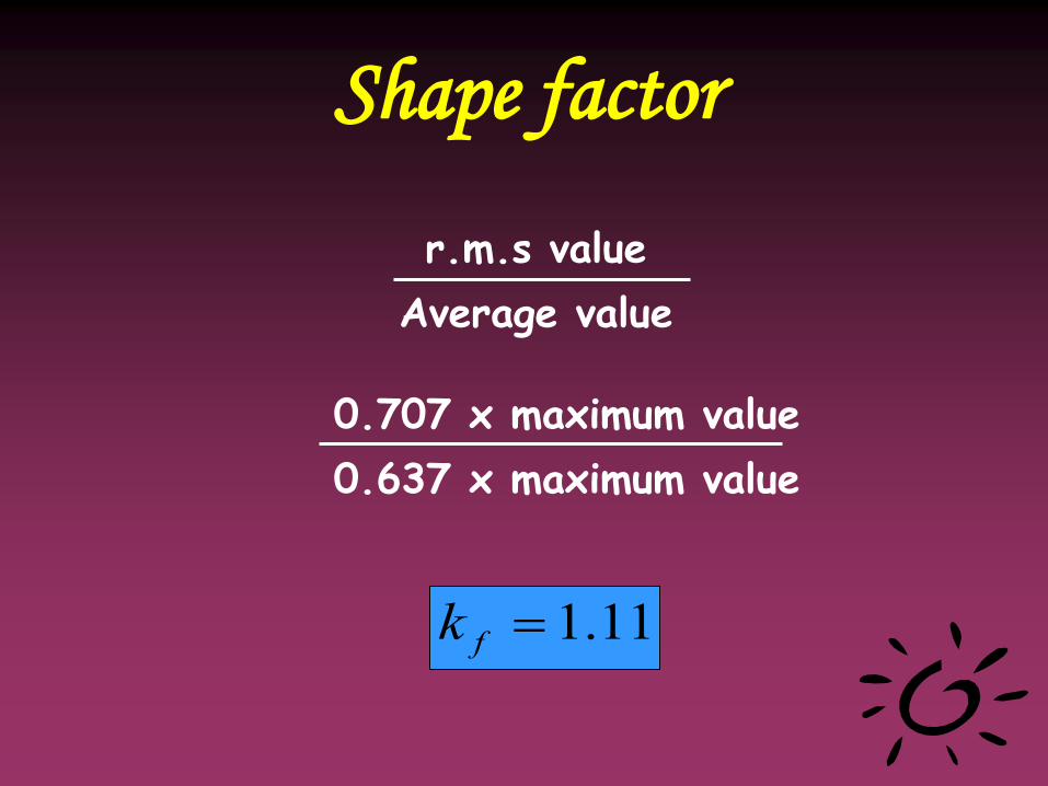
Shape factor
r.m.s value
Average value
0.707 x maximum value
0.637 x maximum value
11.1fk
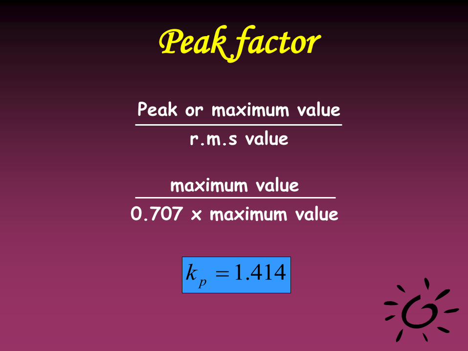
Peak factor
Peak or maximum value
r.m.s value
maximum value
0.707 x maximum value
414.1pk
Conclusion
11.1fk
414.1pk
Shape factor
Peak factor


What is power factor?
• Is the ratio of true power to
apparent power in an AC circuit.
• PF = PT/ PA
Another way...
• PF = EI Cos / EI
• PF = Cos
• Power factor is the cosine of the angle.
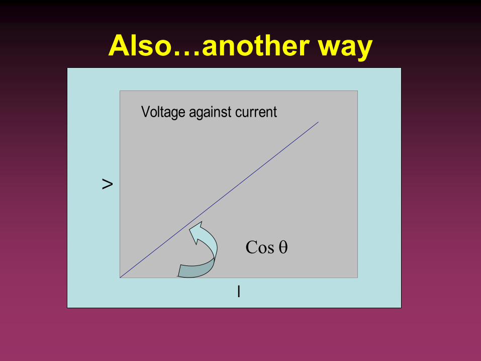
Also…another way
Voltage against current
I
V
Cos

Conclusion
Purely resistive Purely reactive Equal
PF = 1 PF = 0 PF = 0.7071
100% consumed No power consumed 70% consumed


Objectives
• Understand the use of resistance,
inductance and capacitance in circuit
• Understand the concept of R-L-C circuit
in series and parallel
• Determine the total impedance, Z and
current, I in a circuit
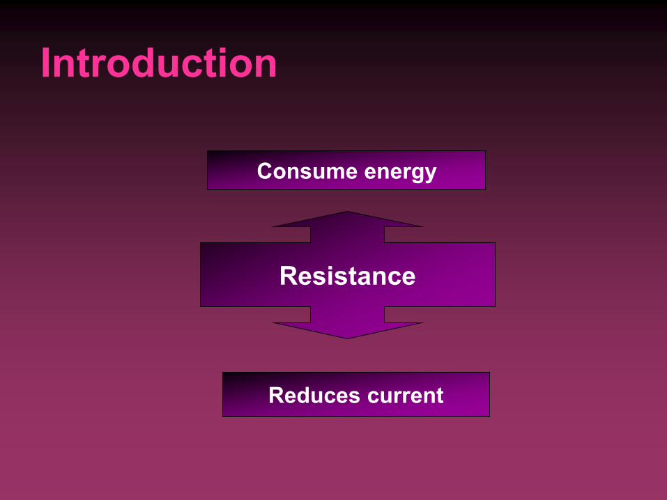
Introduction
Resistance
Consume energy
Reduces current
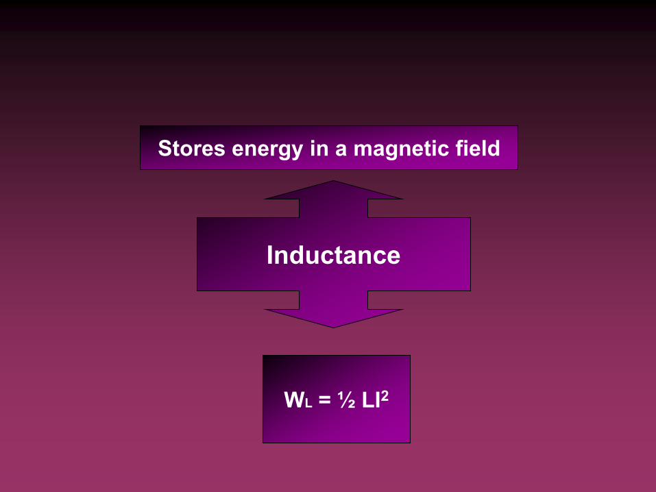
Inductance
Stores energy in a magnetic field
WL = ½ LI2
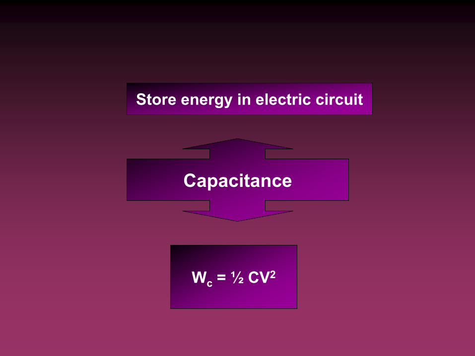
Capacitance
Store energy in electric circuit
Wc = ½ CV2
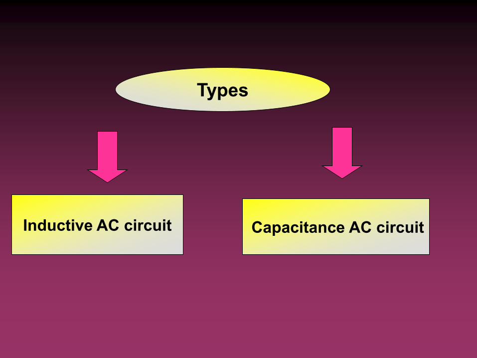
Inductive AC circuit Capacitance AC circuit
Types
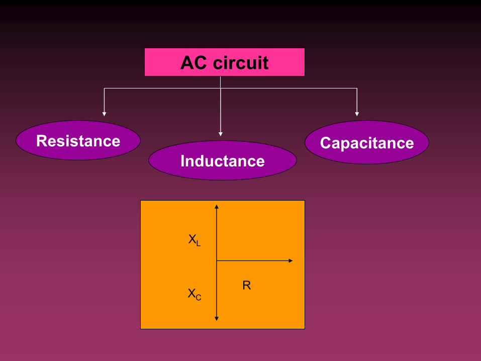
AC circuit
Resistance Capacitance Inductance
XL
XC R

Total Impedance
fLX L 2fC
X c2
1
2 2( )L CZ R X X
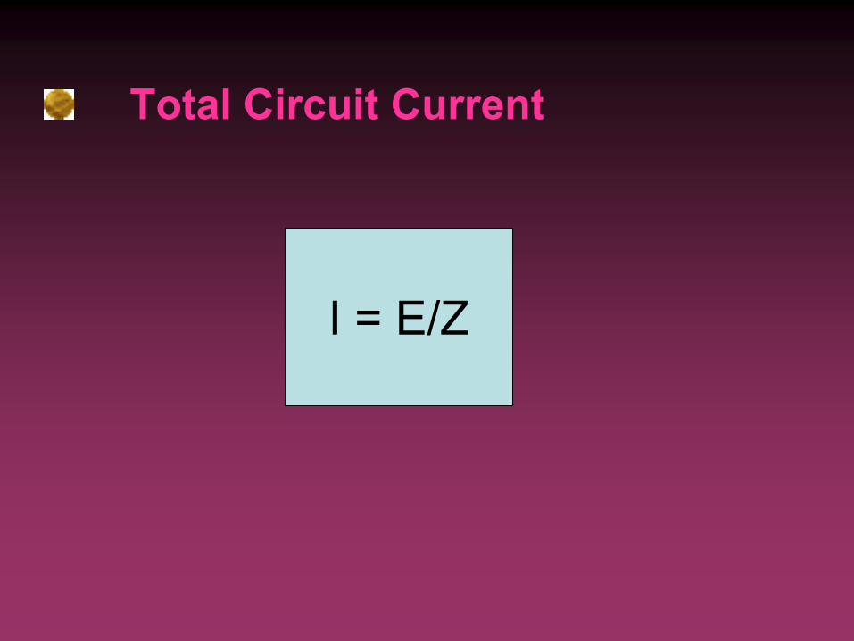
Total Circuit Current
I = E/Z
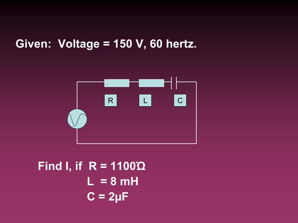
R L C
Given: Voltage = 150 V, 60 hertz.
Find I, if R = 1100Ώ
L = 8 mH
C = 2µF
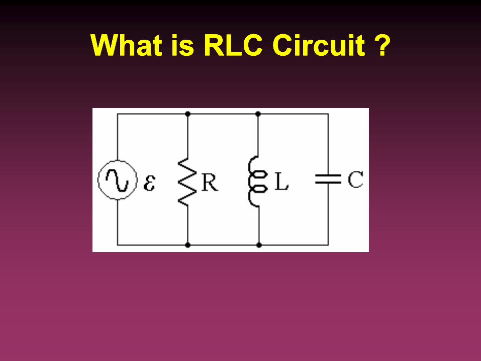
What is RLC Circuit ?What is RLC Circuit ? What is RLC Circuit ?What is RLC Circuit ?
What we want to know?What we want to know? What we want to know?What we want to know?
• To know the value of each components
• To calculate Xc and XL
• To find current of each components
• To calculate total current
• To calculate the impedance
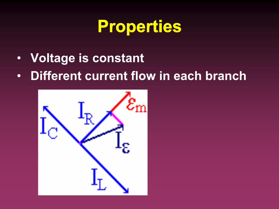
PropertiesProperties PropertiesProperties
• Voltage is constant
• Different current flow in each branch

Step by stepStep by step Step by stepStep by step
1. Value of each components
Resistance Ohm
Inductance Henry, H
Capacitance Farad, F
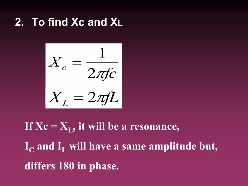
2. To find Xc and XL
fcX c
2
1
fLX L 2
If Xc = XL, it will be a resonance,
IC and IL will have a same amplitude but,
differs 180 in phase.
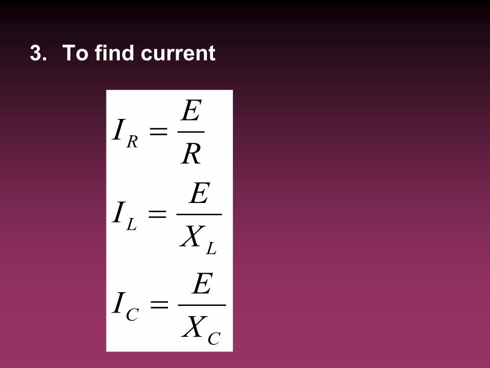
3. To find current
C
C
L
L
R
X
EI
X
EI
R
EI
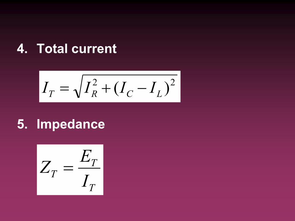
4. Total current
5. Impedance
22 )( LCRT IIII
T
TT
I
EZ


OBJECTIVES
After this lesson, you should be able to:
Define true power
Define apparent power
POWER
Electrical power is the rate at which
electrical energy is converted to another
form, such as motion, heat, or an
electromagnetic field
Power, P (Watt)
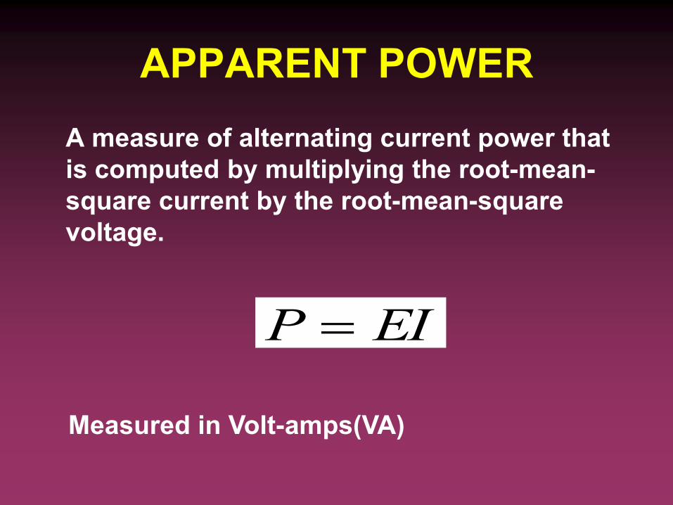
APPARENT POWER
A measure of alternating current power that
is computed by multiplying the root-mean-
square current by the root-mean-square
voltage.
EIP
Measured in Volt-amps(VA)
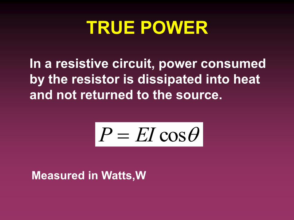
TRUE POWER
In a resistive circuit, power consumed
by the resistor is dissipated into heat
and not returned to the source.
cosEIP
Measured in Watts,W
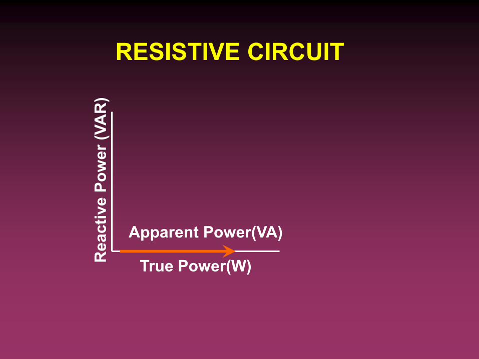
RESISTIVE CIRCUIT
Apparent Power(VA)
True Power(W)
Reacti
ve P
ow
er
(VA
R)
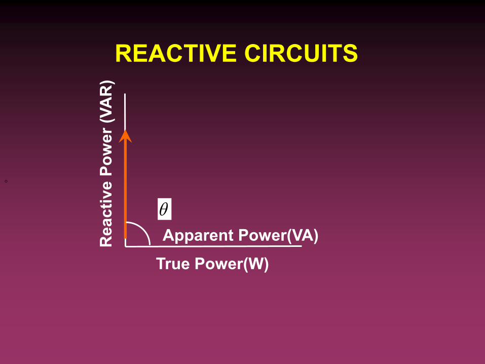
REACTIVE CIRCUITS
Apparent Power(VA)
True Power(W)
Reacti
ve P
ow
er
(VA
R)

APPLICATION
Electric Utility Company
- supply both true and apparent power
- apparent power is larger than true power thus
current supplied will be larger
- cost will arise
- Utility company will raise its raise for customers
operating at low power factors


Single-Phase Circuit Connection
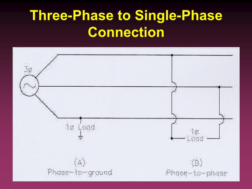
Three-Phase to Single-Phase
Connection
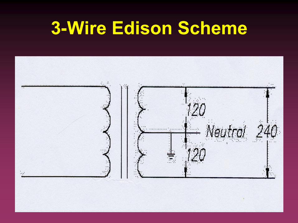
3-Wire Edison Scheme

Summary
If a circuit is purely resistive, the current is in phase with the voltage. If it is purely inductive, the current lags the voltage by 90°. If the circuit is purely capacitive, the current leads the voltage by 90°.
If a circuit contains both resistance and inductance, the current lags the voltage by an angle less than 90o but the angle is greater than 0°.
If a circuit contains resistance and capacitance, the currents leads the voltage by an angle less than 90°, but the angle is greater than 0°
REFERENCES
• Edward Huges, “Electrical
Technology,” 8th Edition, Prentice Hall
• Theodore Wildi, “Electrical Machines,
Drives and Power Systems” 5th Edition,
Prentice Hall
• Marizan Sulaiman, “Analisis Rangkaian
Sistem Kuasa Elektrik Moden” Utusan
Publications